

GreenEcoTherm GP XX SC Series, GP 20 sc, GP 32 sc, GP 25 sc, GP 18 sc Installation, Operation And Maintenance Manual
Page 1
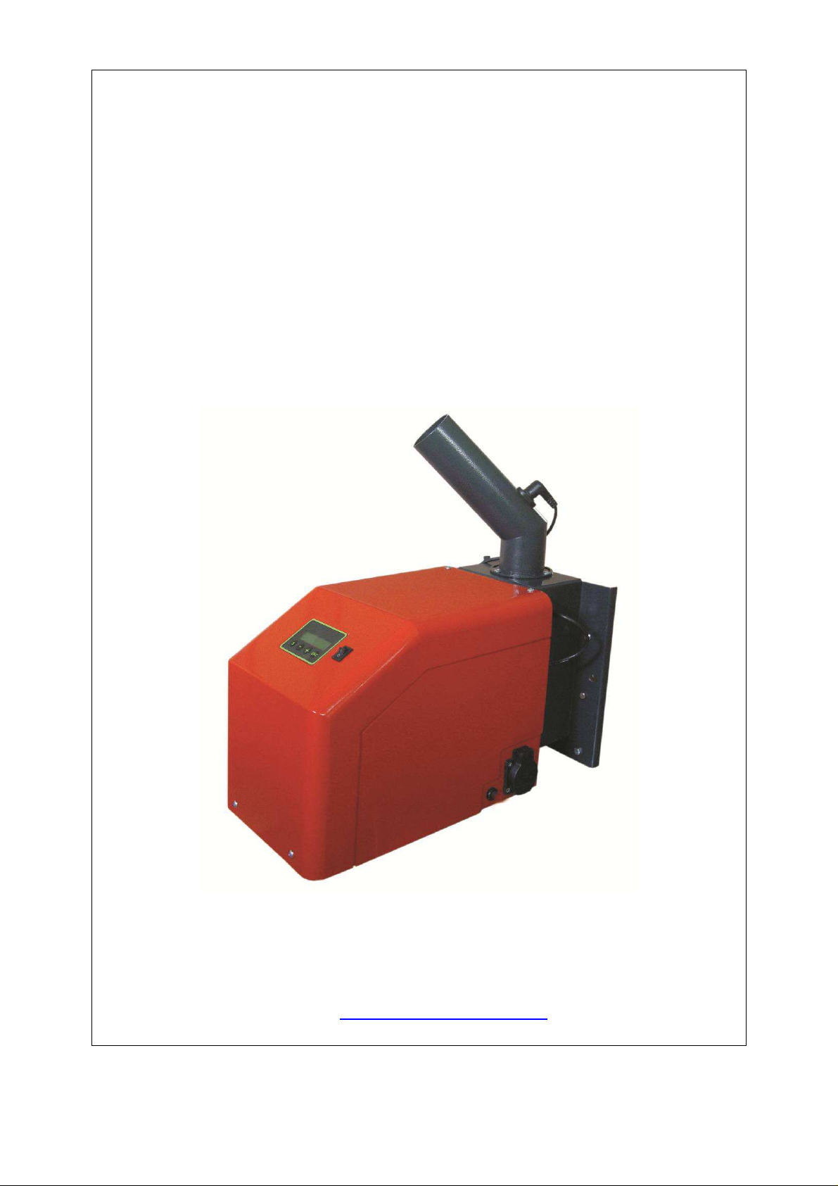
MANUAL
FOR INSTALLATION, OPERATION AND MAINTENANCE OF
AN AUTOMATED PELLET BURNER FROM SERIES
“GP xx sc”
http://www.greenecotherm.eu
Pellet burner GP xx sc 1
Page 2

Manufacturer
ZMM Haskovo PLC
Address
Phone number
Fax
e-mail
home page
67 Saedinenie blvd., 6300 Haskovo, Bulgaria
+359 800 15 145
+359 38 603 070
The manufacture company thanks you for your choice.
The manufacture company submits this manual to help the team that will install, adjust and
service the pellet burner, as well as to the customer that will operate it.
The manufacturing company requires that the technicians, performing the above mentioned
procedures, had successfully passed the product’s technical training.
Manual for installation, operation and maintenance of an automated pellet burner from series
“GP xx sc”
(Edition: 13.11.2013 г. 14:48)
Pellet burner GP xx sc 2
Page 3

CONTENT
page.
1. USERS SAFETY INFORMATION. ................................................................................................. 4
2. DESCRIPTION AND ADVANTAGES OF THE AUTOMATED PELLET BURNER “GP xx sc”. ..... 5
3. TECHNICAL DATA OF THE AUTOMATED PELLET BURNER FROM SERIES “GP xx sc”. ....... 7
4. CONSTRUCTION DESCRIPTION OF THE AUTOMATED PELLET BURNER “GP xx sc”. ....... 10
4.1. GENERAL CONDITIONS. ................................................................................................... 10
5. MOUNTING AND INSTALLATION OF THE PELLET BURNER. ................................................. 11
5.1. MAIN REQUIREMENTS FOR INSTALLATION OF A PELLET BURNER ”GP xx sc”. ........ 11
5.2. INSTALLATION OF THE PELLET BURNER. ...................................................................... 11
5.3. OVERALL DIMENSIONS OF THE BURNER’S MAIN MODULE. ....................................... 11
5.4. POSITIONING AND MOUNTING OF THE BURNER’S MODULES. ................................... 12
5.5. INFORMATION ABOUT INSTALLATION AVAILABILITIES OF AN AUTOMATED PELLET
BURNER “GP xx sc” AND ITS CO-OPERATION WITH HOT WATER BOILERS. .......................... 13
6. INITIATION TO OPERATION OF THE AUTOMATED PELLET BURNER “GP xx sc”. ............... 14
6.1. MAIN REQUIREMENTS ABOUT THE USED FUEL TYPES. ............................................. 14
6.2. INITIATION TO OPERATION OF A PELLET BURNER FROM SERIES “GP xx sc”. ......... 14
6.2.1. INTERFACE PANEL OF AN AUTOMATED PELLET BURNER “GP xx sc”. ................... 15
6.2.2. CONNECTING AND POWER SUPPLYING OF THE BURNER. ..................................... 15
6.2.3. SWITCHING ON THE PELLET BURNER FROM SERIES “GP xx sc”. ........................... 16
6.2.4. ALGORITHM OF OPERATION OF A PELLET BURNER “GP xx sc” .............................. 16
6.2.5. OPERATIONAL PARAMETERS FOR ADJUSTMENT OF A BURNER “GP xx sc” ......... 18
6.2.6. DESCRIPTION OF THE PRIMARY MENU, THE METHODS OF STARTING AND
OPERATIONAL PARAMETERS ADJUSTMENT OF A PELLET BURNER “GP xx sc” .................... 19
6.2.7. BURNER ADJUSTMENTS ACCORDING TO THE CONSUMED HEATING OUTPUT ... 22
6.2.8. NOMINAL OPERATION MODE OF THE BURNER. ........................................................ 22
6.2.9. OPERATION MODES OF A PELLET BURNER FROM SERIES “GP xx sc”................... 22
6.2.10. USER MENUS IN THE CONTROL MODULE OF A PELLET BURNER “GP xx sc”. ....... 24
6.2.11. MENU “EFFECT LEVEL”. ................................................................................................. 24
6.3. ADJUSTMENT OF THE BURNER’S HEATING OUTPUT. ................................................. 26
6.3.1. DECREASING THE BURNER’S HEATING OUTPUT. ............................................... 26
6.3.2. INCREASING THE BURNER’S HEATING OUTPUT. ................................................ 26
6.4. STOPPING THE OPERATION OF A PELLET BURNER FROM SERIES “GP xx sc”. ....... 26
6.4.1 STOPPING THE OPERATION OF A PELLET BURNER FROM SERIES “GP xx sc”
THROUGH THE SWITCH “START”. ................................................................................................ 26
6.4.2. STOPPING THE OPERATION OF A PELLET BURNER FROM SERIES “GP xx sc”
THROUGH A MENU FROM ITS COTROLLER KEYBOARD. ......................................................... 26
6.5. SWITCHING OFF A PELLET BURNER FROM SERIES “GP xx sc” THROUGH EXTERNAL
MODULE, MANAGING ITS OPERATION. ....................................................................................... 28
6.5.1. EMERGENCY SHUT DOWN OF A PELLET BURNER FROM SERIES “GP xx sc”. . 28
6.6. MENU DISPLAYING A LIST WITH THE LAST FAILURES, OCCURRED DURING
OPERATION OF A PELLET BURNER FROM SERIES “GP xx sc”. ................................................ 29
6.7. RESTART OF THE PELLET BURNER OPERATION. ........................................................ 29
6.8. DESCRIPTION OF THE TEMPERATURE STICKERS FUNCTION FOR MONITORING OF
THE SYSTEM’S CONDITION. .......................................................................................................... 29
6.9. CLEANING AND MAINTENANCE OF A PELLET BURNER FROM SERIES “GP xx sc”. .. 31
6.10. USER INTRODUCTION WITH THE MAINTENANCE AND ADJUSTMENTS
PROCEDURES OF A PELLET BURNER FROM SERIES “GP xx sc” ............................................. 32
6.11. SAFETY AND UNPREDICTED RISKS. .......................................................................... 32
6.12. COMPLETION OF THE BURNER’S WARRANTY CARD. ............................................. 33
6.13. ACTIONS AFTER EXPIRY OF THE LIFE CYCLE OF A PELLET BURNER FROM
SERIES “GP xx sc”. .......................................................................................................................... 33
7. FAILURES AND TROUBLESHOOTING. ................................................................................. 34
8. WIRING DIAGRAM OF AN AUTOMATED PELLET BURNER FROM SERIES “GP xx sc”. ....... 38
Pellet burner GP xx sc 3
Page 4
1.
USERS SAFETY INFORMATION.
The manual for installation, operation and maintenance of the automated pellet burner from
series “GP xx sc” is designated for end users and authorized servicing specialists.
The users must know that:
All activities regarding installation of the pellet burner should be performed only by an
authorized installers, which have acquired legal rights by the legal authorities;
All activities regarding the electrical installation must be performed only by electrical-
technicians;
The primary technical initialization to operation, including visual check of the entire
heating installation, adjustments and start of the pellet burner must be performed by a
person that is authorized by the manufacturer.
Please observe the following conditions during installation, start, adjustment and initialization
to operation of the automated pellet burner from series “GP xx sc”:
All legal provisions regarding safety;
All legal provisions regarding environment protection;
Provisions regarding installation, start and adjustment;
All harmonized provisions of the European Union, applicable for your country;
Please strictly observe the presented safety instructions, in order to avoid any risks or harms
to people, properties and environmental polluting.
Please pay attention to the following symbols in the present manual book:
Danger
This symbol warns the users about possible health risks.
Warning
This symbol warns the users about possible risks and harms to properties and
environment.
Information
This symbol presents texts with additional information for the users.
The current manual book uses notation “GP xx sc”, which includes the pellet
burner models "GP 20_18 sc” with heating output of 18kW, “GP 25 sc” with
heating output 25kW and pellet burner “GP 32 sc” with installed heating output
of 32kW.
For your personal safety and before taking any actions regarding the
appliance installation and operation, it is highly recommended to read
carefully this manual book. Non-compliance to the instructions presented
below might lead to fatal consequences, for which the manufacture company
will not be responsible.
Pellet burner GP xx sc 4
Page 5

2. DESCRIPTION AND ADVANTAGES OF THE AUTOMATED PELLET BURNER
FROM SERIES “GP xx sc”.
The automated modulating pellet burner from series “GP xx sc” utilizing wood pellets is
designated for mounting to hot water boilers and other appliances. The burner utilizes wood
pellets and other types of biomass, which are described below, as the generated heat energy
is adopted by the boiler body’s heat exchanging surfaces, to which it is mounted or by other
heat energy consuming appliances.
The pellet burner from series “GP xx sc” delivery kit consists of:
Main module – 1pc;
Fuel transport auger – 1pc;
Flexible pipe – 1pc, with locking brackets – 2 pcs;
A pair of working gloves – 1pc;
Manual for operation – 1pc;
Main module package – 1pc;
Fuel transport auger package – 1pc;
Manual for installation, operation and maintenance of a pellet burner from series
“GP xx sc” – 1pc.
The automated pellet burner from series “GP xx sc” can utilize the following fuel types:
Wood pellets with diameter Ø 6-8mm, from categories ENplus-A1, ENplus-A2 and
ENplus-B according to standard EN 14961-2:2010, or categories A, AB, B, BC, C,
CD, E, EF according to the manufacture company’s classification;
Dried nuts (from cherries, from morello);
Mixture of pellets and nuts (for example in 50% - 50% ratio);
Other biomass with pellet shape, but after approval test in the burner manufacture
company’s laboratory.
The pellet burner from series “GP xx sc” is equipped with:
Microprocessor controller managing the burner’s modules;
Display panel with keyboard, used to manage the burner’s modules;
Fan for fresh firing air supply equipped with Holl sensor, which controls the rotation
frequency;
Electrical heating element used for ignition of the fuel;
Auger for automatic fuel transportation from a hopper to the burner;
Combustion chamber, in which an optimal burning process is realized;
Photic sensor for dynamic control of the burning process;
Reversible temperature sticker for indication of the system’s operation mode and of
the necessity for cleaning of the appliance/chimney, to which it is fixed;
Irreversible temperature sticker for indication of registered overheating of the burner,
used also as precondition to deny a warranty claim.
The pellet burner is equipped with:
System for automatic fuel ignition;
System for automatic feeding of the fuel to the burner’s combustion chamber;
System for automatic cleaning of the combustion chamber
Security system, which blocks the burner in case the fuel feeding inlet pipe has been
overheated, as a result from emergency situations;
Photic sensor for dynamic control of the burning process;
System for modulation of the firing air flow rate during the process of initial fuel
ignition;
System for modulation of its operation mode, providing optimal operation modes and
low fuel consumption;
Availability to perform final combustion followed by blowing, through a defined period
of time, for cleaning purposes and for new automatic restart.
Pellet burner GP xx sc 5
Page 6

Advantages of the pellet burner:
The burner is designated for biomass utilization, which makes it ecologically clean
and does not contribute to environment polluting and to planet’s global warming;
It is used to replace the fuel type in boilers for utilization of wood and coal;
Modern and multifunctional microprocessor control module, made in Sweden,
providing precise operation of the burner’s process components, through parameters
adjustment;
Automatic testing of the system’s functions;
Five levels for modulation of the heating output through quick access, as they can be
easily changed by the users;
Automatic modulation – adjustment of the needed fresh air quantity, according to the
heating output chosen by the user;
Automatic self-adjustment of the system, according to the transport auger’s feeding
rate / productivity, to specific climate conditions and to the fuel’s caloricity;
Indication of the heat carrier (or water) temperature in the boiler;
Availability to save the current adjustments and to restore the factory settings;
Passwords for limiting the access to certain levels, to parameters for the users and
for the servicing staff;
Availability for operation with temperature sensor, boiler and room thermostats;
Special measures to increase the reliability and the safety of the product;
Independence from the quality of the burned wood pellets with diameter Ø 6-8mm;
Availability to choose from 4 types of adjustments, depending on the quality of the
burned pellets, at stable efficiency;
Innovative and unique automatic cleaning of the combustion chamber, through
mechanical scraping of the combustion chamber’s fire-grate;
Availability to control a circulations pump;
Availability to control a flue extraction fan;
Easier servicing through the control module’s function – “History errors”;
The burner is equipped with system for automatic fuel ignition;
Simplified installation and adjustment of the burner, which accelerates the installer’s
work;
High efficiency;
Low harmful emission;
Automatic fuel feeding from a hopper, which can be build according to the local
conditions (it is not included in the burner’s standard delivery kit);
Simplified maintenance;
Minimum operation costs.
Pellet burner GP xx sc 6
Page 7
+1100
3. TECHNICAL DATA OF THE AUTOMATED PELLET BURNER FROM SERIES “GP
XX SC”.
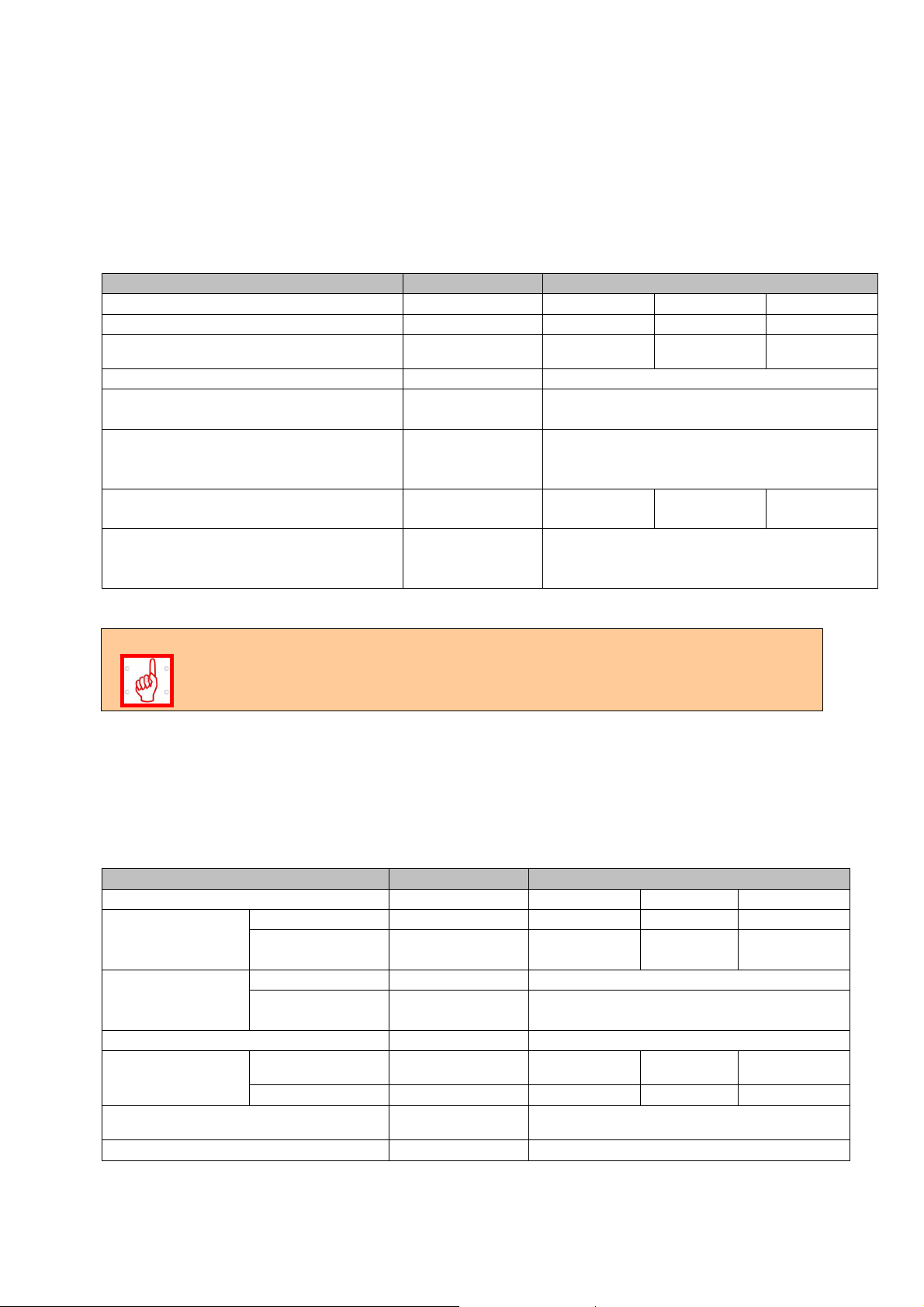
The technical data of the automated pellet burner from series “GP xx sc”, operating with
wood pellets, is presented in Table 3.1.
Table 3.1. Technical parameters of the automated pellet burner from series “GP xx sc”,
operating with wood pellets.
PARAMETER DIMENSION VALUE
Burner model - GP 20_18 sc GP 25 sc
GP 32 sc
Nominal heating output kW 18 25 32
Heating output adjustment range kW 7-18 7-25 10-32
Used fuel - Wood pellets
Wood pellets category according to
- ENplus-A1, ENplus-A2 и Enplus-B
standard EN 14961-2:2010
Used pellets categories (according to
- A, AB, B, BC, C, CD, E, EF
the manufacture company’s
classification)
Wood pellets consumption at nominal
kg/h 4.2 5.3 6.8
heating output
The quantity depends on the pellets ash
Wastes after complete fuel burning Ash
content and on the burner’s operation
mode
The automated pellet burner from series “GP xx sc” is designated for utilization of
wood pellets complying with the classification of standard EN14961-2:2010,
categories ENplus-A1, ENplus-A2 and Enplus-B, and also with the developed
classification by the manufacture company.
The dimensions and technical parameters of the automated pellet burner from series “GP xx
sc” are presented in Table 3.2.
Table 3.2. Dimensions and technical parameters of an automated pellet burner from series
“GP xx sc”.
PARAMETER DIMENSION VALUE
Model - GP 20_18 sc GP 25 sc GP 32 sc
Weight
Main module kg 19.6 19.6
Fuel feeding
kg 8.5 8.5 8.5
19.6
auger
Overall
dimensions
(WхLхH)
Main module mm 250х705х 488
Fuel feeding
auger
mm 184x1520x107
Power supply voltage - L1, N, PE, 50Hz; 230V;
Electrical
consumption
In nominal mode
In ignition mode A 4.5 4.5 4.5
Electrical power W
A 0.2 0.2 0.2
<100
(with ignition)
Electrical protection - IP20
Table 3.3 Recommended fuel parameters.
Pellet burner GP xx sc 7
Page 8

≥
<
≥
<
≥
<
≥
<
≥
<
PARAMETER DIMENSION VALUE
Pellets diameter mm 6 - 8
Recommended fuel caloricity (low temperature of
combustion)
Wood pellets category according to standard EN
14961-2:2010
Wood pellets category A, AB, B, BC, C, CD, E, EF
Ash content % See tables 3.4 and 3.5
Water content % Max. 8 – 10%
Wood pellets classification, developed and applied by the manufacture company, depending
on their physical properties is presented in table 3.4.
Table 3.4. Wood pellets classification, developed and applied by the manufacture company,
depending on their physical properties.
PELLETS CATEGORY AD DU
A
AB
B
BC
C
CD
D
DE
E
EF
In which:
Ad – ash content as dry mass, %;
DU – mechanical durability, %.
With the adoption of the new EU standard for wood pellets (EN 14961-2) in 2010, a new
certificate ENplus for wood pellets used in domestic hot water boilers has been introduced,
as well as EN-B for industrial pellets used in industrial hot water boilers (Table 3.5). The
ENplus standard defines two quality categories: A1 and A2. The strictest limits for content of
ash in the pellets are introduced in class A1. The ash content in class A2 is up to 1.5%. The
certificate EN-B is applied for industrial pellets with reduced quality requirements.
d
A
d
A
d
A
d
A
MJ/kg >17.2
kWh/kg >4.7
ENplus-A1, ENplus-A2 and Enplus-B
%6.0≤
%6.0≤
%0.16.0 ≤<dA
%0.16.0 ≤<dA
%0.2%0.1 ≤<dA
%0.2%0.1 ≤<dA
%0.3%0.2 ≤<dA
%0.3%0.2 ≤<dA
%0.3>
%0.3>
DU
DU
DU
DU
DU
DU
DU
DU
DU
DU
%0.97
%0.97
%0.97
%0.97
%0.97
%0.97
%0.97
%0.97
%0.97
%0.97
Pellet burner GP xx sc 8
Page 9

1)
Table 3.5 Wood pellets standard EN 14961-2:2010
PARAMETER DIMENSION ENplus-A1 ENplus-A2 EN-B
6 (± 1) 6 (± 1) 6 (± 1)
Diameter mm
8 (± 1) 8 (± 1) 8 (± 1)
Length mm 3,15 ≤ L ≤ 40 1) 3,15 ≤ L ≤ 40 1) 3,15 ≤ L ≤ 40
Bulk density kg / m2 ≥ 600 ≥ 600 ≥ 600
Caloricity MJ / kg ≥ 16,5-19 ≥ 16,3-19 ≥ 16,0-19
Water content Ма .-% ≤ 10 ≤ 10 ≤ 10
Dust Ма .-% ≤ 1 3) ≤ 1 3) ≤ 1 3)
Mechanical durability Ма .-% ≥ 97,5 4) ≥ 97,5 4) ≥ 96,5 4)
Ash Ма .-% 2) ≤ 0,7 ≤ 1,5 ≤ 3,5
Ash melting point °C ≥ 1200 ≥ 1100 -
Chlorine content Ма .-% 2) ≤ 0,02 ≤ 0,02 ≤ 0,03
Sulfur content Ма .-% 2) ≤ 0,03 ≤ 0,03 ≤ 0,04
Nitrogen content Ма .-% 2) ≤ 0,3 ≤ 0,3 ≤ 1,0
Cuprum content mg / kg 2) ≤ 10 ≤ 10 ≤ 10
Chromium content mg / kg 2) ≤ 10 ≤ 10 ≤ 10
Arsenic content mg / kg 2) ≤ 1,0 ≤ 1,0 ≤ 1,0
Cadmium content mg / kg 2) ≤ 0,5 ≤ 0,5 ≤ 0,5
Mercury content mg / kg 2) ≤ 0,1 ≤ 0,1 ≤ 0,1
Plumbum content mg / kg 2) ≤ 10 ≤ 10 ≤ 10
Nickel content mg / kg 2) ≤ 10 ≤ 10 ≤ 10
Zink content mg / kg 2) ≤ 100 ≤ 100 ≤ 100
1) No more than 1% of the pellets can be longer than 40mm, as the maximum length is
45mm;
2) Defined from dry mass;
3) Particles <3.15mm, fine dust particles, before delivery of the goods;
4) For measurements through “Lignotester” maximum allowed value is ≥ 97.7 mass %.
Logo of ENplus-A1 Logo of ENplus-A2 Logo of EN-В
Pellet burner GP xx sc 9
Page 10
4. CONSTRUCTION DESCRIPTION OF THE AUTOMATED PELLET BURNER FROM
SERIES “GP XX SC”.
4.1. GENERAL CONDITIONS.
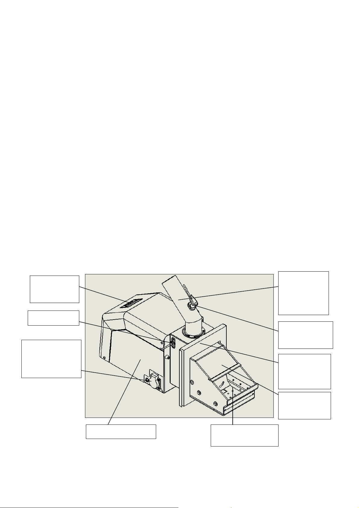
The main part from the construction of a pellet burner from series “GP xx sc” is the main
module, which consists of:
Combustion chamber, which forms conditions for optimal burning process and is
made of high quality stainless steel;
Combustion chamber’s fire-grate;
System for automatic cleaning of the combustion chamber;
Air distribution tract, which provides equal firing air feeding and also cooling of the
burner’s components;
Heating element, which ignites the fuel, positioned under the tilted part of the
combustion chamber’s fire-grate;
Firing air feeding fan, equipped with sensor for controlling of the rotation frequency
and also for adjustments;
Photic sensor, which monitors the burning process, mounted on the burner’s side and
with availability for easy cleaning;
Emergency temperature sensor for protection from the so called “back fire” in the
main module’s pellets feeding pipe;
Control module, which monitors and manages the burner’s operation;
Display panel with keyboard, which visualizes the burner’s operation mode and is
used to perform the necessary adjustments;
Connector for the fuel transport auger, used to supply the auger with electrical power;
Flexible pipe, made of special transparent high temperature resistant material (in
case of fire it does not separate toxic substances), used to connect the auger and the
main module of the burner.
Figure 4.1. View of the main module of a pellet burner from series “GP xx sc”.
Interface panel
(display +
keyboard)
Pellets feeding
inlet pipe to
combustion
chamber
Photic sensor
Socket for power
supply and control
of the transport
auger
Main module housing Combustion
chamber’s fire-grate
Pellet burner GP xx sc 10
Emergency
sensor for “back
fire” protection
Flange for
mounting of the
main module to
an appliance
Combustion
chamber
Page 11

5. MOUNTING AND INSTALLATION OF THE PELLET BURNER.
5.1. MAIN REQUIREMENTS FOR INSTALLATION OF A PELLET BURNER FROM
SERIES ”GP XX SC”.
The following requirements must be observed during installation of a pellet burner from
series “GP xx sc”:
The burner must be positioned in a way providing enough free space for its cleaning
and maintenance;
The burner must be mounted to appliance (hot water boiler, or other heat energy
consumer) in a way providing availability for easy maintenance and cleaning of the
appliance;
It is not allowed to mount the burner to appliance, which has been installed in living
premises, including corridors;
The installation and mounting of the burner to appliance must be performed only by a
qualified technician;
The installation and maintenance of the automated pellet burner must be performed
by specialized companies which have acquired legal rights for such activities;
The automated pellet burner from series “GP xx sc” must be connected to the
electrical supply installation only by an authorized electrical technician;
Before initiation of the burner to operation, the heat energy consuming appliance’s
operational condition must be checked;
The burner attendance must be performed only by adult persons, which are well
familiar with the appliance’s manual for operation.
The mounting of the burner to a boiler (consumer-appliance) can be performed
through bolts (or studs) and nuts. The tightening of the burner has to be
performed by a tool (for example wrench). It is not allowed to fix it through
handles or others. The fixing and dismounting operations of the burner must be
performed by a qualified person equipped with proper tools.
5.2. INSTALLATION OF THE PELLET BURNER.
The installation of the pellet burner from series “GP xx sc” to appliance requires preliminary
prepared technical project, complying with the acting provisions and regulations:
In case the consuming appliance is a hot water boiler, then the requirements
presented in standard BNS EN 303-5/2000 – “Hot water boilers for central heating
part 5 – Hot water solid fuel boilers with nominal heating output up to 300 kW –
terminology, tests and notifications”, must be observed;
In case the heat energy consuming appliance is not a hot water boiler, then the
requirements presented in the relevant standards for such type of appliances must be
observed;
Fire safety provisions;
About the electrical supply network – BNS EN 60335-1/1997 – “Securing of electrical
domestic appliances”.
When installing a pellet burner to a hot water boiler, please observe the relevant
chimney draught requirements, presented in the boiler’s technical data sheet.
5.3. OVERALL DIMENSIONS OF THE BURNER’S MAIN MODULE.
Figure 5.1 and 5.2 present the overall dimensions of the burner’s main module, which have
to be taken in mind during the mounting and installation of the appliance.
Pellet burner GP xx sc 11
Page 12

Figure 5.1. Main module’s overall dimensions of a pellet burner from series “GP xx sc”.
Figure 5.2. Overall dimensions of the burner’s main module.
5.4. POSITIONING AND MOUNTING OF THE BURNER’S MODULES.
The main module of a pellet burner from series “GP xx sc” has to be mounted horizontally to
the appliance, which will consume the heat energy generated by the fuel burning. Depending
on the appliance type a technical evaluation has to be performed in advance, regarding the
burner’s main module position, in order to achieve reliable operation, easy cleaning,
maintenance and servicing.
The burner’s main module has to be mounted to the heat energy consuming appliance by
using the attached sealing. The fuel transport auger has to be positioned near to the burner,
in order to ensure the connection between it and the main module through the flexible tube,
through which the fuel transits. It is also recommended that the tilting angle between the
transport auger and the horizontal plane is fixed to 45o, which will provide optimal operation
of the auger’s electric motor and of the burning process.
Pellet burner GP xx sc 12
Page 13
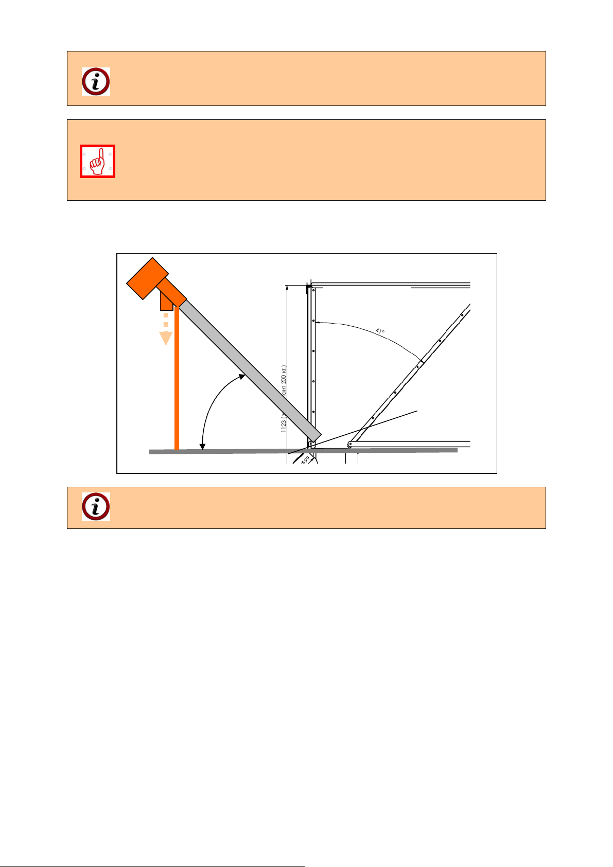
In order to ensure optimal operational conditions of the fuel transport auger it is
recommended to use a pellet hopper “BP” – produced by the burner’s
manufacture company. This hopper is not included in the standard delivery kit of
the pellet burners from series “GP xx sc”.
Change of the auger’s tilting angle leads to changes in the fuel consumption and
respectively to the burner’s heating output:
- Decreasing the auger’s tilting angle leads to increased fuel consumption,
respectively to increased heating output;
- Increasing the auger’s tilting angle leads to decreased fuel consumption,
respectively to decreased heating output.
Figure 5.3 presents a scheme for installation and positioning of the fuel transport auger.
Figure 5.3. Scheme for installation and positioning of the fuel feeding auger.
Fuel Hopper”
“BP”
45о
The auger on the scheme is equipped with metal support bar, which is optional
equipment to the burner’s delivery kit. The auger’s axis has to be positioned at
45o angle relative to the horizontal plane.
5.5. INFORMATION ABOUT INSTALLATION AVAILABILITIES OF AN AUTOMATED
PELLET BURNER FROM SERIES “GP XX SC” AND ITS CO-OPERATION WITH
HOT WATER BOILERS.
The automated pellet burner from series “GP xx sc” is a standalone module (requires power
supply and signal – assignment for operation), which can be mounted to a heat energy
consuming appliance. The practice shows that the heat energy consuming appliance is most
frequently a hot water boiler, used in local heating installation. The manufacture company
has accomplished continues tests for compatibility, reliability and efficiency of the burner in
co-operation with series of popular hot water boilers. Depending on the hot water boiler
model additional transition modules and components might be used, in order to improve the
system’s performance that is consisting of a pellet burner and a hot water boiler, and to
increase its efficiency and reliability.
Pellet burner GP xx sc 13
Page 14

6. INITIATION TO OPERATION OF THE AUTOMATED PELLET BURNER FROM
SERIES “GP XX SC”.
The automated modulating pellet burner from series “GP xx sc” has to be initiated
to operation only by a specialized company, authorized for such activities.
6.1. MAIN REQUIREMENTS ABOUT THE USED FUEL TYPES.
During initiation to operation of a pellet burner from series “GP xx sc” the following main
requirements about the used fuel types must be observed:
To achieve complete fuel burning it is necessary to use only dry fuels. It is
recommended to store the fuel in dry and ventilated premises;
It is forbidden to store the fuel next to the appliance to which the burner is mounted or
at distance less than 400 mm from it;
The optimal recommended distance between the appliance (to which the pellet
burner is mounted) and the fuel is at least 1000 mm. It is preferable to store the fuel in
a neighbor room;
When installing the pellet burner from series “GP xx sc” to the desired appliance and
when storing the fuel, all fire safety requirements must be observed. It is
recommended to position a fire-extinguisher at an easy access and safe place near
the boiler.
6.2. INITIATION TO OPERATION OF A PELLET BURNER FROM SERIES “GP XX SC”.
When initiating to operation a pellet burner from series “GP xx sc”, the following main
requirements must be observed:
Maintenance and attendance of the burner must be performed in accordance to the
manual for maintenance and operation;
The operation mode of the system: a pellet burner from series “GP xx sc” and a heat
energy consumer, must provide minimum under-pressure (pressure lower than the
atmosphere’s) in the appliance’s combustion chamber, within range 5 – 20Pa;
Non-compliance with the above requirement might lead to emergency modes or
to ineffective operation of the burner. The value of the under-pressure in the heat
energy consuming appliance’s combustion chamber depends on the chimney
draught and on other modules (for example a flue gas extraction fan). Operation
modes, non-complying with this requirement might be ascertained through the
temperature value indicated by the reversible temperature sticker.
Any interference to the operation of the appliance that might lead to risks for the
health of the servicing/attending personal or to other indirectly linked people is strictly
forbidden;
During operation the burner has to be periodically checked by the user/attending
staff;
The user must not perform any repairs over the system’s modules. If a failure or a
problem occurs during operation then the users must ask for technical assistance by
a servicing company;
It is forbidden to increase the burner’s heating output above the nominal output;
The ash residues from the burning process must be gathered in proper fire-proof
container and after cooling to ambient temperature it has to be dumped to proper for
the purpose places.
Pellet burner GP xx sc 14
Page 15
6.2.1. INTERFACE PANEL OF AN AUTOMATED PELLET BURNER FROM SERIES “GP
menu)
menu)
XX SC”.
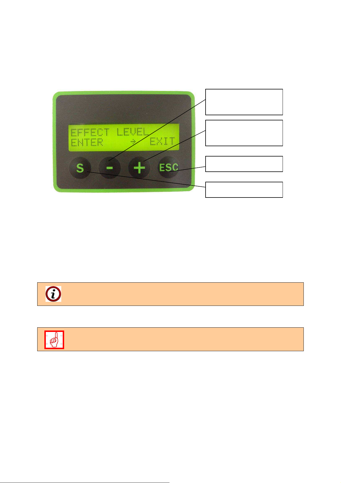
Figure 6.1 presents a view of an interface control panel equipped with display and keyboard,
used to manage the automated pellet burner from series “GP xx sc”.
Figure 6.1. Interface panel of a pellet burner from series “GP xx sc”.
Components of the interface control panel and their functions:
Button “ S ” – is used to choose a submenu and to confirm the performed
adjustments;
Button “ - ” – is used to decrease a currently changing parameter value from the
controller’s menu;
Button “ + ” - is used to increase a currently changing parameter value from the
controller’s menu;
Button “ESC” – is used to cancel a change of chosen parameter from the controller’s
menu and to exit a chosen operational menu.
The above presented buttons of the burner’s interface control panel might have
another function, which will be described on the display panel.
.
6.2.2. CONNECTING AND POWER SUPPLYING OF THE BURNER.
All activities over the burner’s electrical installation, adjustments requiring
dismounting of cover panels or other components, which protect from direct
contact with electrical parts, must be performed only by qualified staff.
The burner must be connected to the electrical installation of the appliance to which it is
mounted, by observing all technical safety rules. Use the power supply cable and the
attached wiring diagram for connecting to power supply voltage and to the burner’s operation
control module.
The fuel feeding auger is mounted to the hopper and is positioned in a way providing the
required fuel feed rate, as it is also filled with fuel.
The sensitive component of the circulations water temperature sensor has to be mounted in
a sleeve for measuring of the outlet water temperature of the hot water boiler or has to be
screwed in a threaded orifice (depending on the sensor type).
Button “-” (its function
depends on the chosen
Button “+” (its function
depends on the chosen
Button “Escape”
Button “Enter”
Pellet burner GP xx sc 15
Page 16

6.2.3. SWITCHING ON THE PELLET BURNER FROM SERIES “GP XX SC”.
The burner switching ON has to be performed through the power supply of the appliance, to
which it is mounted. If the burner has been in operational mode (or in “hot reserve”) but the
power supply has been interrupted, then when the power supply restores the burner will
continue its operation automatically.
In case the appliance to which the burner is mounted is not properly sealed and
the burner is operating, smoking of flue gasses through the unsealed sections is
possible to occur, as well as through the fuel feeding flexible pipe. It is
recommended to seal these sections and to adjust the burner’s heating output in
order to avoid such smoking. The same effect might be monitored during the
transition seasons – autumn and spring, when the natural chimney draught is
decreased due to higher ambient temperatures.
During the burner’s ignition mode the heating elements activate, which are
positioned under the combustion chamber’s fire-grate. This zone is heated to
high temperatures and could be dangerous in case it is touched – manipulations
in the burner’s combustion chamber zone should not be performed. If necessary
to stir (spread) or remove the fuel then proper tools and personal protection
equipment must be used.
When initiating the burner to operation for the first time the auger (fuel feeding)
device must be filled with pellets – this is continues process requiring time.
Therefore the auger must be connected to external power supply, through its
standard plug and to wait until the fuel starts to drop from its top orifice. After that
it must be connected to the power supply socket of the burner’s main module.
The burner’s main module constantly checks if the feeding auger is connected to
its socket and if this condition is not fulfilled the system will transit to emergency
mode, until the auger’s power supply cable is connected properly. After that it is
necessary to restart the burner’s main module in order to transit to normal
operational mode.
If the power supply cable of the transport auger has been disconnected from the
burner’s main module socket (this situation is treated by the controller as an
emergency mode – i.e. there is no motor connected to the socket) and the burner
has been operating at that time, then an emergency mode activates and the
burner operation stops. To reset the alarm it is necessary to connect the auger’s
plug back to the burner’s main module and to switch the burner’s power supply
button to position OFF and then back to ON (restart).
The burner operates through a preliminary set algorithm, which is installed in its
control module. The optimal operation parameters are adjusted in the
manufacture company’s factory and their change is generally not required.
6.2.4. ALGORITHM OF OPERATION OF A PELLET BURNER FROM SERIES “GP XX
SC”.
The pellet burner starts operation when the following conditions are observed:
The burner’s main module is mounted to the appliance to which it will operate;
Presence of electrical power supply;
Activated start through the display panel;
Installed circulations water temperature sensor – in case such method is used to
regulate the burner’s operational mode;
Pellet burner GP xx sc 16
Page 17

Lack of emergency signals;
The fuel hopper and the transport auger are filled with fuel.
When the above conditions are fulfilled the control module executes the following algorithm:
Submits power and the external transport auger, the heating element and the firing air
feeding fan switch ON;
After expiry of the preliminary set (by the manufacturer) time, which provides loading
of the combustion chamber with the so called “ignition” fuel doze, the auger’s power
supply cuts off and it stops;
After the photic sensor in the burner registers presence of burning process the
heating elements power supply cuts off. For a defined period of time the burner
reaches the assigned heating output. If the photic sensor does not register a flame
within a set period of time, the controller performs new attempt for ignition through the
above presented algorithm. The ignition attempts are limited to two;
In case of successful fuel ignition the system transits to nominal operation mode of
the burner, which is realized through periodical fuel feeding and pauses for burning.
The times for fuel feeding and pauses are adjusted in the control module’s software.
The burner heating output can be changed by selecting one of its output levels;
The maximum heating output level - 5
-th
of the burner is not recommended. This
level should be chosen only in cases when the used fuel type is with lower
caloricity value or when higher heating output is temporarily needed. The
recommended output levels are from 1 to 4, as normally level 4 reaches the
nominal heating output.
A NTC sensor is used as control device for determining of the circulations water
operational temperature:
- When the assignment is nearly reached the burner’s control module
decreases its heating output (so called modulation of the operation mode);
- If the circulations water temperature decreases the burner restores its
heating output.
If the operation signal drops out during operation (for example by room thermostat),
then the burner will switch off through the above presented algorithm;
If during rest the operation assignment changes and it receives signal for operation,
then it will start operation through the above presented algorithm. The same condition
is valid in case the circulations water temperature is lower than the adjusted in the
burner’s control module;
If the fuel does not ignite within the first attempt a new attempt is automatically
performed, as the ignition attempts are maximum two (defined by the manufacturer).
In case of second unsuccessful ignition there is possibility of presence of unburned
fuel over the main module’s fire-grate. It is necessary to find and remove the reason
for unsuccessful ignition and also to clean the combustion chamber’s fire-grate from
the fuel residues;
If the gathered fuel over the burner’s fire-grate has not been removed, after
successful ignition (for example after restarting the burner) it might lead to difficult
firing of relatively larger amount of fuel, to separation of inflamed gasses and
respectively to their explosive ignition. Such explosive ignitions might lead to
mechanical damages of the appliance, to which the burner’s main module is
mounted.
If the photic sensor does not register a burning process during operation, then the
fuel ignition algorithm starts again;
If two unsuccessful attempts for ignition have been performed, for example in case
the fuel has been depleted, then the burner stops the main algorithm and transits to
emergency mode, which is shown on the display panel and should be considered as
Pellet burner GP xx sc 17
Page 18

a necessity for intervention by the user, as the failure reason requires removal. After
the failure has been removed the new start has to be performed through consecutive
switching OFF and then back ON (restarting) of the appliance’s common power
supply, to which the burner is also connected.
Before starting the burner’s fire-grate has to be checked for presence of unburned
fuel and ash. If so, the fuel and the ash residues have to be removed.
If the power supply has been interrupted the burner will start automatically when the
supply restores.
During operation the burner might transit to final combustion and blowing, if the
relevant option for cleaning during operation is switched ON – parameter
“Max.comb.time”. This parameter is in “Advance menu”, as the access to it is
password protected.
6.2.5. OPERATIONAL PARAMETERS FOR ADJUSTMENT OF A PELLET BURNER
FROM SERIES “GP XX SC”.
The operational parameters are preliminary set in the burner’s control module by the
manufacturer, as the user and/or other attending staff are not required to perform changes.
In order to achieve optimal and economic operational conditions of the burner it is necessary
to assign such heating output that will provide optimal operation and low fuel consumption.
The practice shows that the constant operation of the burner provides optimal fuel
consumption.
The controller’s display panel and the keyboard are used to show information about the
burner’s operation mode. The operational parameters adjustments have to be performed by
trained specialist.
Pellet burner GP xx sc 18
Page 19
6.2.6. DESCRIPTION OF THE PRIMARY MENU, THE METHODS OF STARTING AND
OPERATIONAL PARAMETERS ADJUSTMENT OF A PELLET BURNER FROM
SERIES “GP XX SC”.
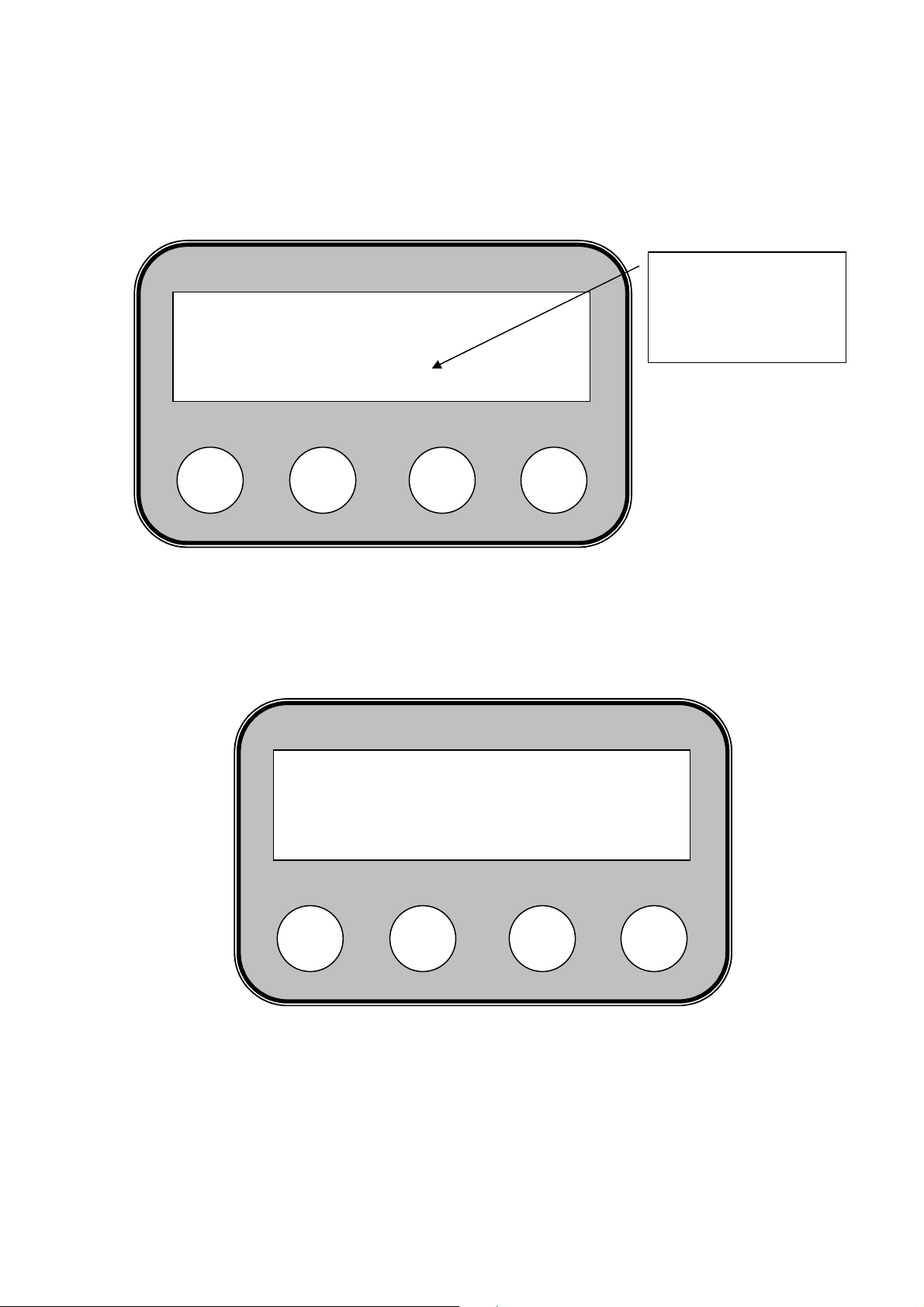
Figure 6.2. Starting display, shown when starting an automated pellet burner from series
“GP xx sc”.
After the software has been loaded (after a few seconds) the display panel shows a question:
whether to start the burner? (Activate?):
Figure 6.3. Menu for starting a pellet burner from series “GP xx sc”, through inviting question.
To start the burner’s operation press the button “S”, as presented on the figure.
After starting the burner’s operation a message is shown on the display panel, as presented
on the next figure.
S
GREEN ecoTHERM
V2.3 2E
_
Activate?
ENTER
S
_
+
ESC
+
Version of the
software for
management of the
burner
ESC
Pellet burner GP xx sc 19
Page 20
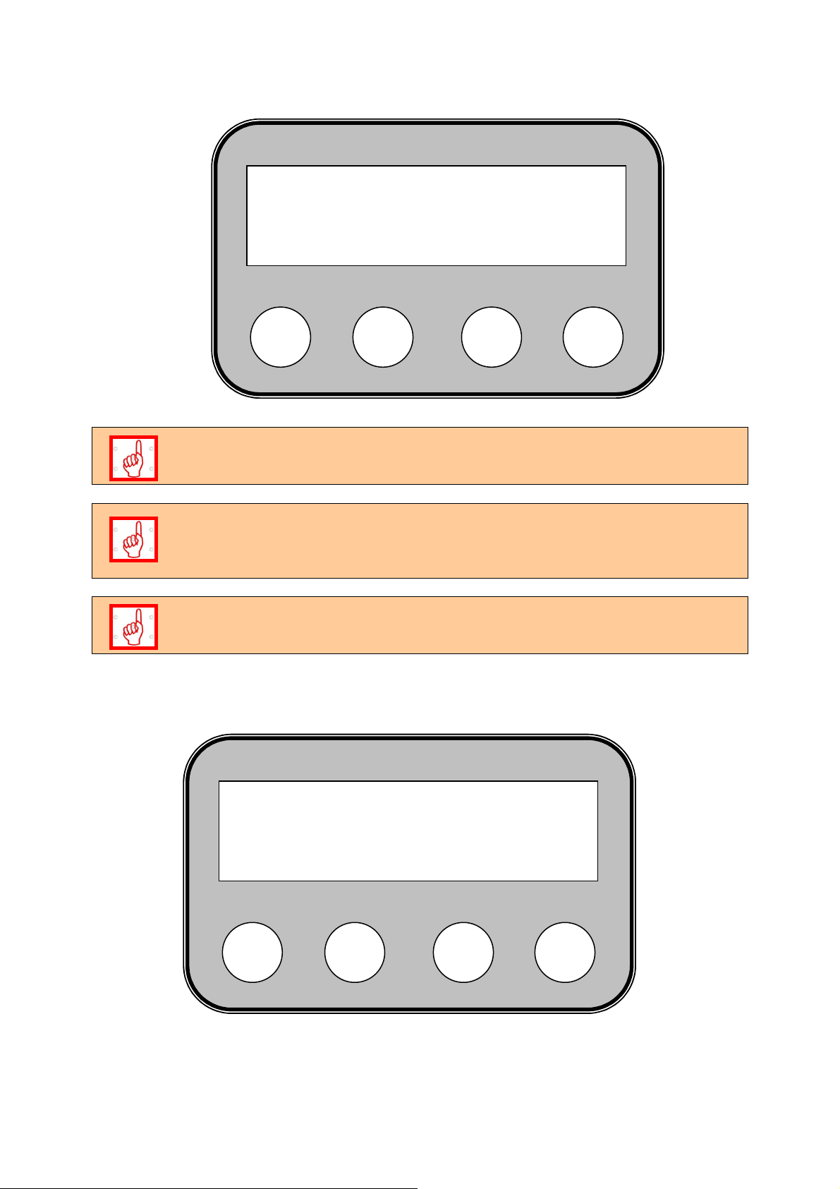
Figure 6.4. The display shows information about the operation mode of the burner’s
o
controller – in this case it checks the operation of the firing air feeding fan.
TEST – BLOWING: – shows the operation mode – a starting blowing of the
burner’s fire-grate through the fan is processed (shows the current phase from
the burner’s ignition).
”32о” – shows (at the lower left corner of the display panel, over the button “S”)
the water temperature in the hot water boiler (degrees Celsius). The temperature
value is displayed if a water temperature sensor is installed and the option is
activated from the controller menu.
”FC: 0% ” – shows the light intensity of the photic sensor, in percent – it is shown
at the lower right corner of the display panel, over the button “ESC”.
Figure 6.5. The display panel shows information about the burner’s operation mode – in this
TEST - BLOWING
32
S
case ignition of the primary fuel doze.
IGNITION 1 150
32o FC: 0%
S
_
FC: 0%
_
+
+
ESC
ESC
Pellet burner GP xx sc 20
Page 21

After the starting blowing by the fan, the burner feeds primary fuel doze and starts the
process of ignition. The display panel shows ”IGNITION 1” – first attempt for ignition, which
has to be completed within a period of time, defined in the controller’s software.
The burner’s controller is factory programmed with the optimal operation mode adjustments.
Discrete number of heating output levels are set, through which the burner operates. The
last, maximum level of the heating output is adjusted in a way that provides higher heating
output than the burner’s nominal output – this mode is designated for situations when the
used fuel caloricity is lower than the normal or when the heat energy consumption exceeds
the burner’s nominal output.
Only short time for operation (totally 10 hours for entire heating season) of the burner in
modes exceeding its nominal heating output are recommended, because such modes lead to
increased heat-loading of the burner’s construction and to decreased life resource.
The practice shows that the factory adjusted parameters of the burner do not need additional
corrections, even if different fuel types are used.
The manufacture company reserves its rights to change the settings of the
appliance, without obligation to inform the end users.
The values of the parameters, which define the heating output of the pellet burner from
series “GP xx sc”, are determined under the following conditions:
The utilized wood pellets are with diameter Ø 6-8mm, quality category ENplus-A1,
ENplus-A2 and ENplus-B, according to standard EN 14961-2:2010 or category: A,
AB, B, BC, C, CD, E, EF (see Tables 3.4 and 3.5);
The tilting angle between the longitudinal axis of the transport auger and the
horizontal plane is 45o;
The ash content (mineral, inflammable mass) does not change significantly the fuel’s
calorific value, but requires special construction of the burner in order to achieve
efficient and economic burning process. Therefore the applicability and efficiency of a
certain fuel have to be tested and after positive results such fuel should be utilized by
the burner;
The manufacture company reserves its right to change the default parameters, which
manage the burner’s operation, without obligation to inform its customers;
Table 6.1 presents the factory settings of the heating output levels, through which the
burner achieves optimal operation performance;
The presented heating output levels define the heating output and the operation
modes of the burner;
The primary adjustment of the burner at the customer’s site is performed by trained
servicing technician, after that the user is not required to perform more changes;
The next texts below describe how to define the fuel consumption and to calculate the
burner’s heating output:
Switch the burner ON;
Dismount the flexible pipe, that connects the auger and the main module, from the
burner and direct the free end to a container (for example plastic bag or other), so the
dropped pellets by the auger gather inside;
Then an authorized technician chooses the menu ”Advance menu” and activates
the parameter ”Stoker adj”;
The access to this menu is protected by password!
Pellet burner GP xx sc 21
Page 22

Leave the auger operating for 6 minutes. The pellets quantity gathered in the
container have to be measured and registered in the controller through the relevant
buttons, as directing information is shown on the display panel. After that activate the
burner operation. The pellets caloricity value can be also entered in the controller, but
only in case that it is necessary and the available information is correct. The factory
adjusted wood pellets caloricity is 4.8kWh/kg. After the data has been entered it must
be saved through the relevant button from the menu – the information on the screen
provides directions about the required steps for completion of the procedure for
primary adjustments. After completing this primary adjustment the burner heating
output is guaranteed.
6.2.7. BURNER ADJUSTMENTS ACCORDING TO THE CONSUMED HEATING
OUTPUT.
For optimal, reliable and efficient operation of the pellet burner from series “GP xx sc” and of
the heat energy consuming appliance, to which it is mounted, is recommended to adjust the
burner according to the needed heat consumption. This can be performed by changing the
burner’s heating output level, as presented in Table 6.1.
When changing the burner’s heating output level it is not necessary to adjust the firing air fan
flow rate. It is performed automatically through the program installed in the burner’s control
module.
6.2.8. NOMINAL OPERATION MODE OF THE BURNER.
After completion of the burner’s starting process (the fuel in the burner’s combustion
chamber is successfully ignited) and the consuming appliance, to which the burner is
mounted and which utilizes the generated heat energy, has been tempered it can be
accepted that the system is in nominal operation mode. Adjustments and checks of the
burner have to be performed in nominal operation mode (as well as of the consumingappliance depending on its operation mode). For the burner it is necessary to assign the
operational heating output, which has to comply with the consumed heating output of the
appliance in nominal operation mode.
In nominal heating output mode the so called “hot test” of the system has to be performed,
according to the acting legal provisions.
The firing air flow rate is significant for the operation mode and the efficiency
of the system – burner and appliance. When the air quantity is less than the
optimal, it might lead to incomplete fuel burning. Also when the air consumption is
higher than the optimal, it leads to cooling of the burning zone and again to
incomplete fuel burning. Therefore it is important to provide free access to air (to
the burner as well as to the room where the system is installed), which to be fed
from the fan to the burning zone, in order to ensure optimal work parameters and
economic operation.
6.2.9. OPERATION MODES OF A PELLET BURNER FROM SERIES “GP XX SC”.
After successful fuel ignition the burner transits through a mode for stabilization of the
burning process, as the display panel shows the following information (Figure 6.6):
Pellet burner GP xx sc 22
Page 23
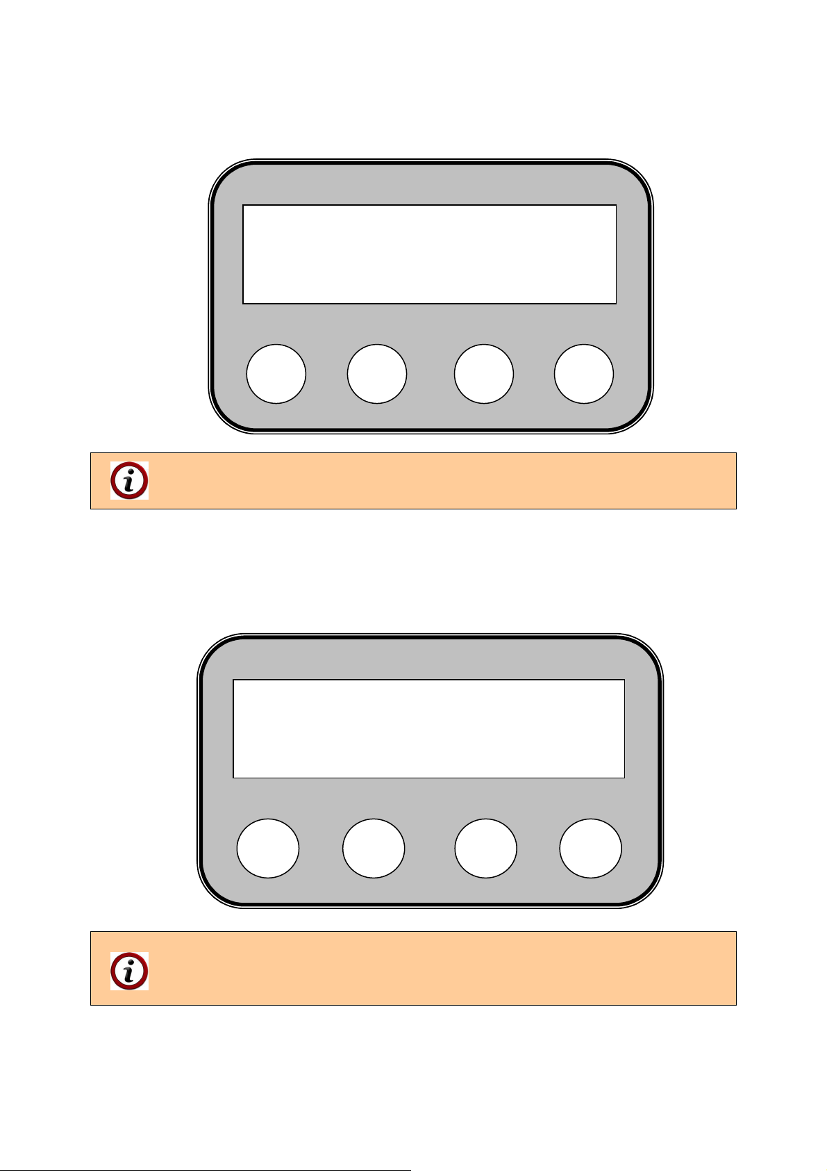
Figure 6.6. The display panel shows information about the burner’s operation mode –
transition mode – transition from ignition to stabilization of the burning process in minimum
heating output mode.
TRANS. : 10kW
32o FC: 65%
S
”TRANS.:10kW” – indicates that the burner is in transitional phase for
stabilization of the burning process, with heating output of 10kW.
After completing the transition mode the burner transits directly to normal operation mode, as
presented on Figure 6.7.
Figure 6.7. The display shows information about the burner’s heating output level, as in this
case it is the maximum heating output mode.
“COMBUST 5 – 35kW” – indicates the burner’s heating output level (in this
case 5th level providing heating output of 35 kW);
“72о”- indicates the current water temperature, oC;
“FC: 98%” – indicates the light intensity by the photic - sensor, %.
COMBUST 5 35kW
72o FC: 98%
S
_
_
+
+
ESC
ESC
Pellet burner GP xx sc 23
Page 24
6.2.10. USER MENUS IN THE CONTROL MODULE OF A PELLET BURNER FROM
SERIES “GP XX SC”.
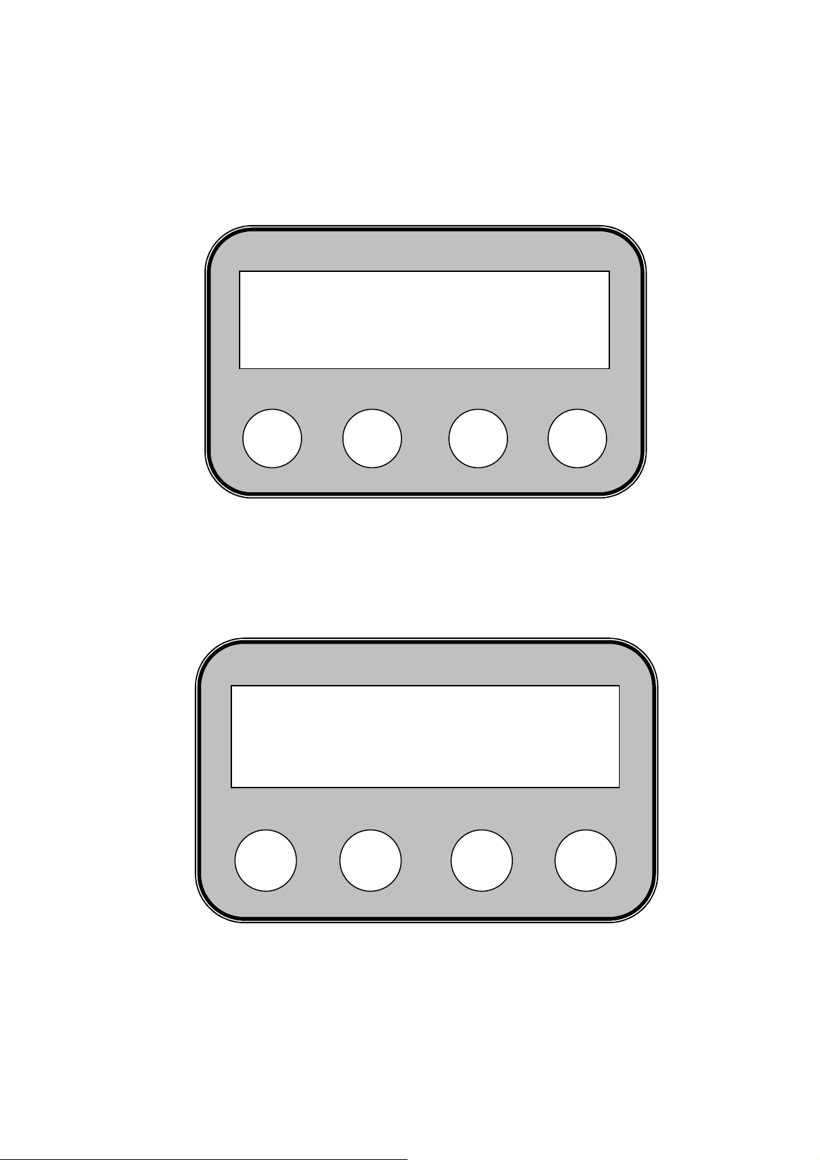
To enter the burner’s menu press and hold the button “S”. To exit already entered submenu
press the button “ESC”.
Figure 6.8. To choose a submenu from the burner’s controller press the button “S”.
6.2.11. MENU “EFFECT LEVEL”.
Figure 6.9. Menu ”EFFECT LEVEL” – choice of a heating output level of a burner from
This menu is used to choose the heating output level for operation of the burner. The heating
output levels values achieved by the burner are presented in Table 6.1
COMBUST 5 35kW
75o FC: 98%
S
EFFECT LEVEL
ENTER EXIT
S
_
series “GP xx sc”.
_
+
+
ESC
ESC
Pellet burner GP xx sc 24
Page 25
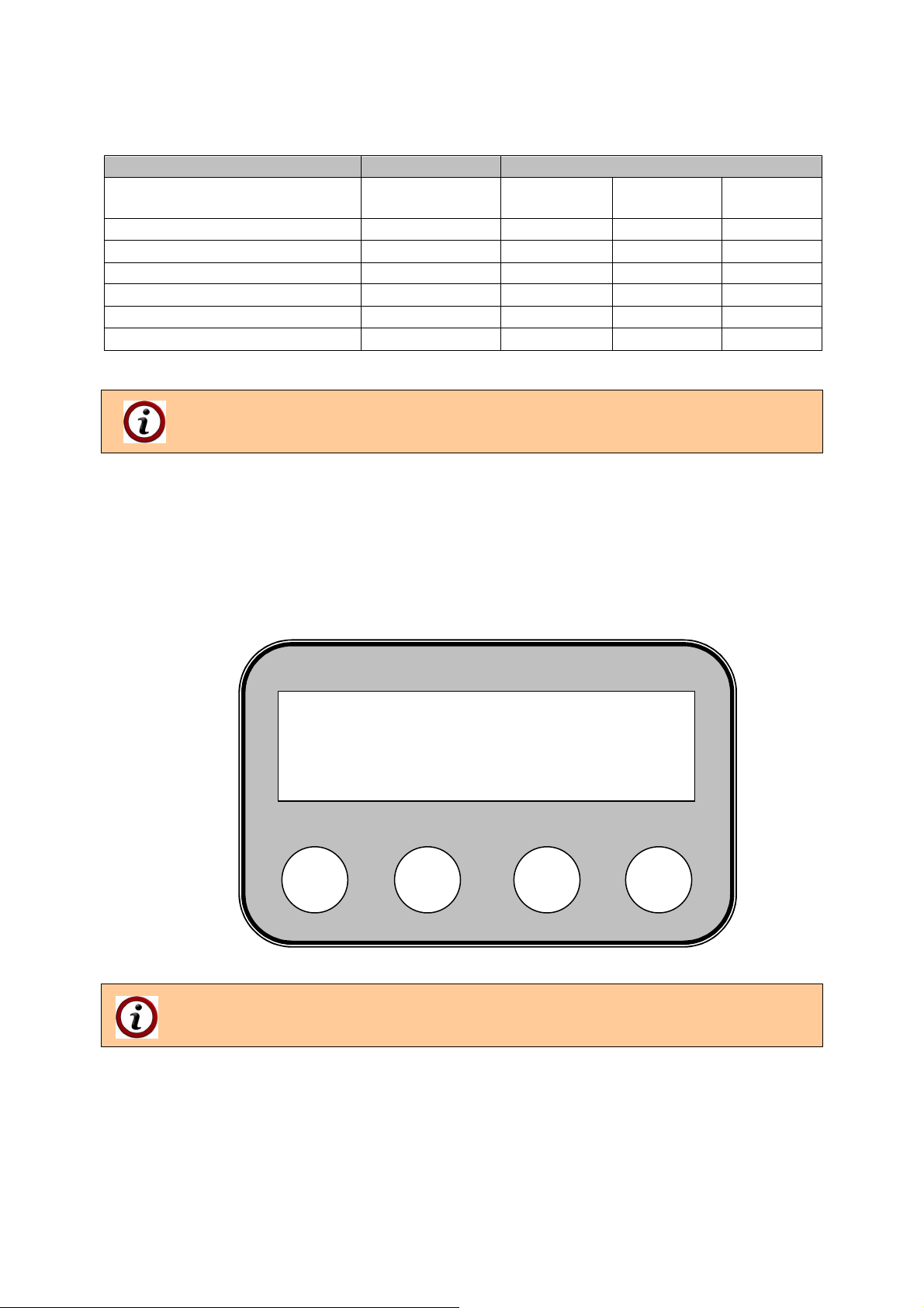
Table 6.1. Heating output of a pellet burner from series “GP xx sc”, depending on the heating
output level.
PARAMETER DIMENSION VALUE
Model - GP 20_18 sc GP 25 sc
Heating output level kW
1 kW
2 kW
3 kW
4 kW
5 kW
It is recommended to operate the burner up to 4th level - including, as the 5th level
should be used exceptionally, but only for short periods of time.
To enter the menu ”EFFECT LEVEL” press the button under ENTER – “S”. To switch to
another menu press the button “+” under the arrow on the display. The button “ESC” is used
to exit the menu and to return to the main menu. When entering the menu ”EFFECT
LEVEL” the user can choose one of the 5 levels of heating output for operation of the
burner.
Figure 6.10. Choice of heating output level of a pellet burner from series “GP xx sc”.
Through the buttons “+” and “–” choose the desired heating output level of the
burner. After that press the button “S” to confirm the changes. To exit the menu
press the button “ESC”.
Effect level [n]
O:5 N:5
S
_
- -
7.0 7.0 10.0
10.0 15.0 20.0
15.0 20.0 25.0
18.0 25.0 32.0
20.0 28.0 35.0
+
ESC
GP 32 sc
-
Pellet burner GP xx sc 25
Page 26

6.3. ADJUSTMENT OF THE BURNER’S HEATING OUTPUT.
The burner’s heating output adjustment can be performed through adjustment of its heating
output level. Information about the burner’s heating output within all different levels is
presented in Table 6.1.
In case the used fuel type has been changed (for example change in the wood
pellets quality category) it might be necessary to re-adjust the burner’s heating
output level.
6.3.1. DECREASING THE BURNER’S HEATING OUTPUT.
It can be performed through decrease of the burner’s heating output level, as the heating
output assignment decreases and respectively the fuel consumption decreases too.
6.3.2. INCREASING THE BURNER’S HEATING OUTPUT.
It can be performed through increase of the burner’s heating output level, as the heating
output assignment increases and respectively the fuel consumption increases too.
When changing the heating output, respectively the fuel consumption, the
controller’s algorithm automatically changes the firing air flow rate supplied by the
fan, which feature ensures optimal operation modes within wide heating output
range.
6.4. STOPPING THE OPERATION OF A PELLET BURNER FROM SERIES “GP XX
SC”.
Stopping the burner operation can be performed through the control module, which submits
command for operation of the burner. Restoring of the burner’s operation can be performed
through changing the control module’s adjustment.
6.4.1 STOPPING THE OPERATION OF A PELLET BURNER FROM SERIES “GP XX
SC” THROUGH THE SWITCH “START”.
Through the button “START” (which has to be installed by the servicing technician during the
burner mounting and in accordance with the attached wiring diagram) the burner can be
started to operational mode and respectively can be switched OFF. When switching the
burner OFF its display panel shows a message “FINAL COMBUSTION”.
The burner switching OFF must be performed only through the switch “START”
and not through stopping the appliance’s power supply. The reason is because
through the switch “START” the burner performs controlled stopping, which
includes cooling of the appliance and complete fuel combustion, as this process
preserves the appliance’s reliability.
6.4.2. STOPPING THE OPERATION OF A PELLET BURNER FROM SERIES “GP XX
SC” THROUGH A MENU FROM ITS COTROLLER KEYBOARD.
The following actions have to be performed in order to stop the burner’s operation:
Press and hold the button “ESC” (for more than 5 seconds);
Choose the answer “YES” when the display shows - ”Make final combustion?“.
When the choice for stopping is confirmed a message ”Final combustion” is shown on the
display panel and the burner performs stopping procedure.
Pellet burner GP xx sc 26
Page 27
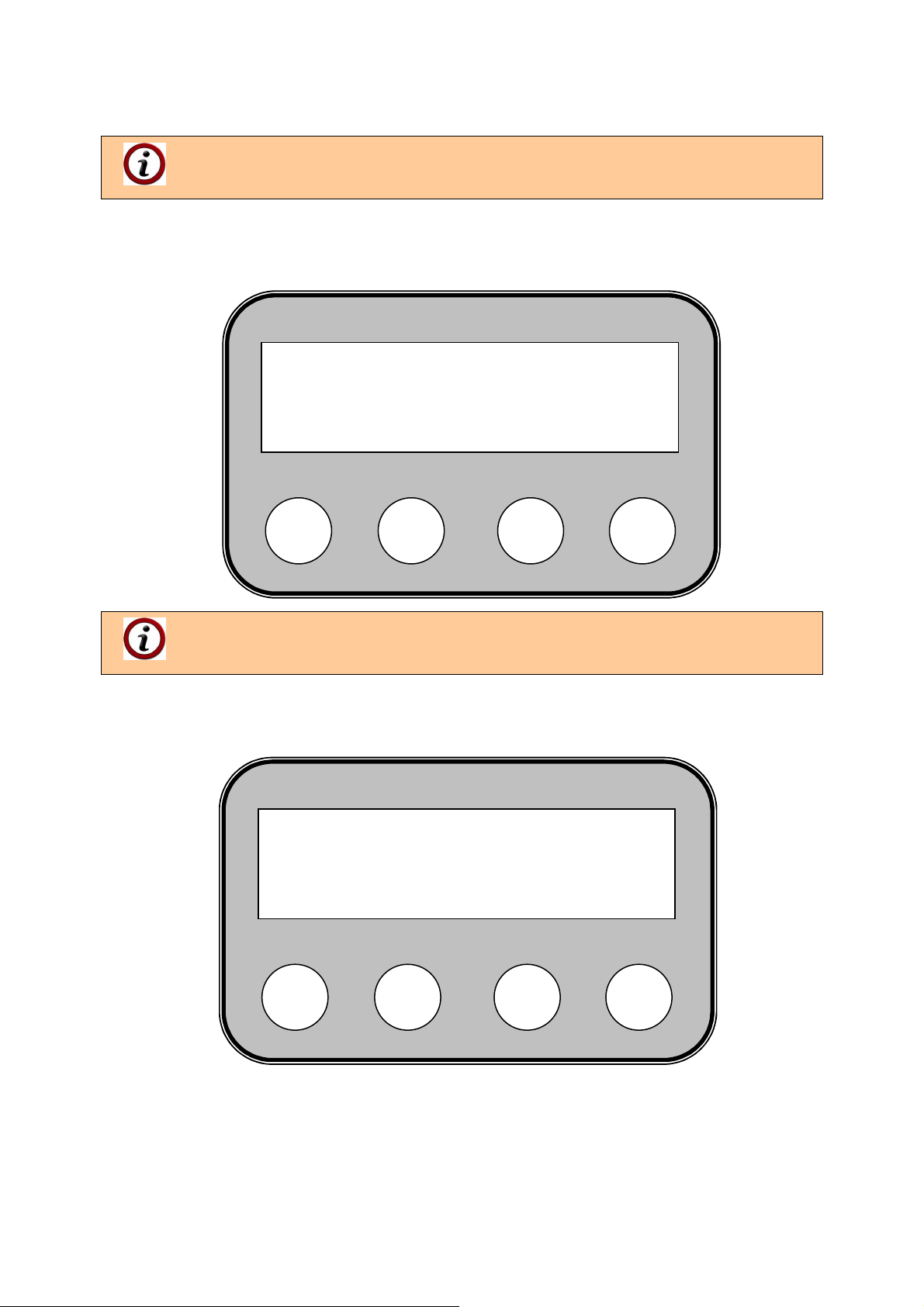
There is also another method for stopping the burner’s operation: through the menu ”MAKE
FINAL COMB.” from the burner’s controller.
This option is used to stop the pellet burner’s operation by performing final
combustion of the fuel, located on the burner’s fire-grate.
Figure 6.11. Choice of the menu ”MAKE FINAL COMB.”, which is used to stop the
operation of a pellet burner from series “GP xx sc”.
To enter the menu ”MAKE FINAL COMB.” press the button “S” and to exit
(cancel) press the button “ESC”. The buttons “+” and “-“ are used to scroll through
the other menus.
Figure 6.12. The controller’s display panel shows a message, asking to start the stopping
To perform fuel final combustion press the button “S”, positioned under the message [YES].
To cancel the process of final combustion or to return to previous menu press the button
“ESC”, positioned under the message [NO].
MAKE FINAL COMB.
ENTER EXIT
S
process of a pellet burner from series “GP xx sc”.
Make final comb.?
[YES] [NO]
S
_
_
+
+
ESC
ESC
Pellet burner GP xx sc 27
Page 28

When the control module receives signal to stop the operation of a pellet
burner from series “GP xx sc” the fuel supply stops, but the firing air feeding fan
continues to operate. Therefore after confirmation of the stopping procedure the
burner continues to operate and to generate heat energy, which makes it inert,
respectively the system in which it operates is also inert. This specific feature has
to be taken in mind especially if the heating radiators are equipped with
thermostatic valves (or other control components), which close the circulations
water flow. As a result of this process it is possible that the generated heat
energy, from the fuel final combustion, can’t be adopted by the heating system
(can’t be unloaded) and to lead to overheating of the appliance. Therefore in case
the pellet burner from series “GP xx sc” is operated in heating systems with
radiator regulation valves, it is necessary not to completely close the radiator
valves, but to adjust them to minimum value. Also one of the radiators should not
be equipped with regulation valve, in order to ensure adoption of the heat energy
generated during the process of final combustion.
6.5. SWITCHING OFF A PELLET BURNER FROM SERIES “GP XX SC” THROUGH
EXTERNAL MODULE, MANAGING ITS OPERATION.
The burner stopping could be performed through an external module or through the
procedure described in the chapter above. When the burner transits from burning mode to
standby mode or to switched OFF mode, then its managing control module performs the so
called “controlled stopping”, during which the firing air feeding fan continues to operate and
the control module monitors for emergency signals. After cooling of the burner it has to be
switched OFF through its power supply. It is also recommended to clean the system - burner
and consuming appliance, from the ash deposits.
6.5.1. EMERGENCY SHUT DOWN OF A PELLET BURNER FROM SERIES “GP XX
SC”.
During operation of the burner emergency situations might occur, as the burner will transit to
emergency mode. Such types of situations are indicated by the burner’s control module,
which automatically performs prevention procedures. The burner’s control module transits to
emergency mode, which is indicated with a relevant failure code message on the burner’s
display panel. Descriptions of the failure codes and other messages are presented in Table
7.2. Description of the possible failures, shown on the control module’s display panel, of a
pellet burner from series “GP xx sc”, is also presented in Table 7.3.
If emergency situation occurs the failure code, indicated on the control module’s display
panel, has to be checked and the relevant corrective measures should be performed. After
that the burner has to be restarted through switching OFF and then back ON its power
supply.
If the consuming appliance, to which the burner is mounted, has been overheated
(emergency situation) its emergency thermostat activates. This thermostat is a
MANDATORY equipment and is not included in the burner’s standard delivery kit.
The reason for the emergency situation has to be determined and the relevant
corrective measures have to be performed. The emergency thermostat has to be
switched back manually, in order to supply the burner with power again.
In case the burner’s pellet feeding inlet pipe has been overheated (also treated as
an emergency situation) the sensor, which monitors the temperature in this zone
and protects the transport auger from the so called “back fire”, activates. After
cooling of the burner’s main module the cause for the emergency has to be
determined and the relevant corrective actions have to be performed. After
removing the reason for emergency, in this case overheating of the burner’s fuel
inlet pipe, the security sensor in that zone might be damaged, as it may requires
replacement.
Pellet burner GP xx sc 28
Page 29
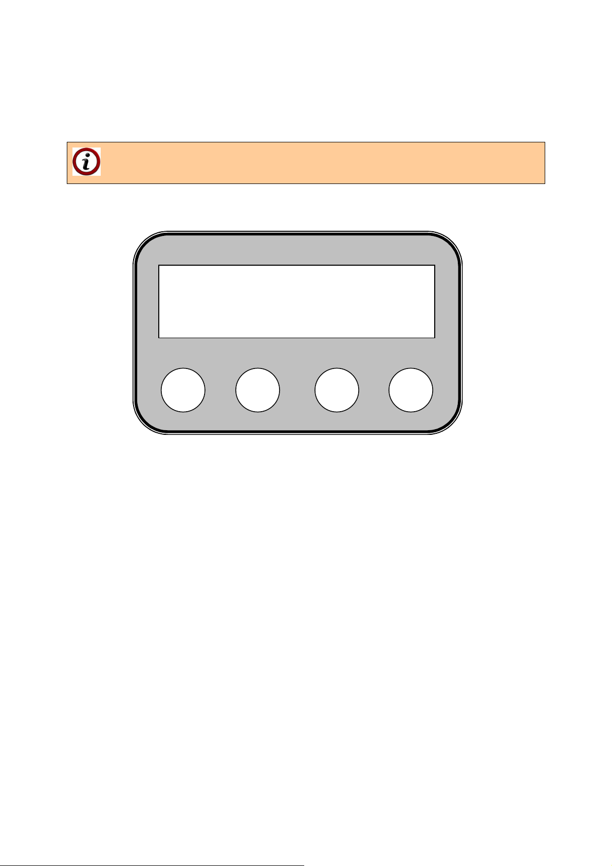
6.6. MENU DISPLAYING A LIST WITH THE LAST FAILURES, OCCURRED DURING
OPERATION OF A PELLET BURNER FROM SERIES “GP XX SC”.
To check the last failures that have occurred during operation of the burner it is necessary to
enter the menu “LOG”.
The menu LOG shows a list only with the last 10 failures, which have occurred
during operation of the burner. In case a new failure occurs it replaces the oldest
one in the list.
Figure 6.13. The controller’s display panel shows the chosen menu “LOG” together with the
failure sequence number and code.
To exit this menu press the button “ESC”.
Table 7.2 provides information about the failure code and its explanation.
6.7. RESTART OF THE PELLET BURNER OPERATION.
The burner restarting is necessary in situations when there is assignment for operation, but
the control module has switched to secured mode and the burner is not operating. The
display panel shows a message with the failure code. The reason for the failure has to be
determined and the relevant corrective measures performed. After that the burner has to be
restarted – it can be performed by switching OFF and then back ON the electrical supply of
the main module (for example through the main switch of the control board to which the
burner is connected).
6.8. DESCRIPTION OF THE TEMPERATURE STICKERS FUNCTION FOR
MONITORING OF THE SYSTEM’S CONDITION.
The temperature sticker is used for measurement of the burner temperature in specific zone.
Through such measurement the system’s condition can be determined, as well as the
necessity for prevention and servicing actions to the appliance, to which the burner is
mounted and/or to the flue tract and more specifically the chimney.
LOG error: 1: 22
S
_
+
EXIT
ESC
Pellet burner GP xx sc 29
Page 30
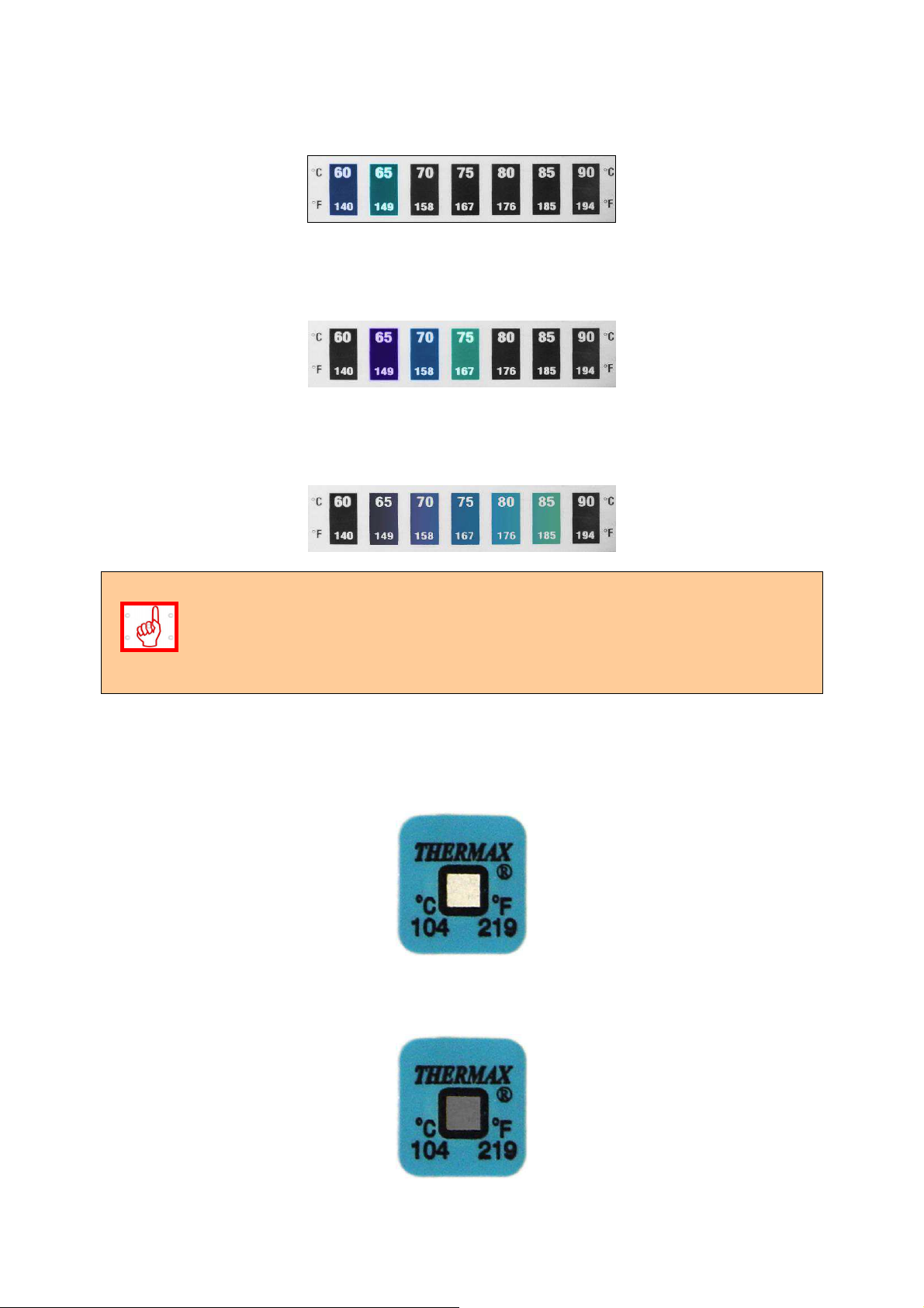
Figure 6.14. View of the reversible (self-restoring) temperature sticker, used to indicate the
operational temperature in the burner’s zone, to which it is stuck up – the example shows
condition of increased temperature within a range of 60 – 65
o
C.
Figure 6.15. View of the reversible (self-restoring) temperature sticker, used to indicate the
operational temperature in the burner’s zone, to which it is stuck up – the example shows
condition of increased temperature within a range of 65 – 75oC.
Figure 6.16. View of the reversible (self-restoring) temperature sticker, used to indicate the
operational temperature in the burner’s zone, to which it is stuck up – the example shows
condition of increased temperature within a range of 75 – 85oC.
The reversible temperature sticker condition has to be checked every time when
the burner or the consuming appliance have been attended. It indicates the
current temperature during burner operation, provides information about the
appliance’s ash contamination level, indicates about necessity for cleaning, as
well as information about the chimney draught and its influence over the operation
of the system – pellet burner – consuming appliance – chimney.
Figure 6.17. View of the irreversible (not self-restoring) temperature sticker – the example
shows its normal condition, i.e. the temperature of the pellets inlet pipe has not been
exceeded over the limit value – 104 oC.
Figure 6.18. View of the irreversible (not self-restoring) temperature sticker – the example
shows its emergency condition, i.e. the temperature of the pellets inlet pipe has been
exceeded over the limit value – 104 oC.
Pellet burner GP xx sc 30
Page 31
The activation of the irreversible temperature sticker is indication that the pellets
inlet pipe of the burner has been overheated. The original condition of the sticker
can’t be restored. It is necessary to determine the cause for its activation, to
perform the relevant corrective measures and after that to replace the sticker with
new one – to be performed by a servicing technician. The activation of this sticker
might occur in cases of increased resistances in the chimney tract or decreased
chimney draught, as well as by presence of hot flue gasses in the flexible pipe
between the auger and the burner’s main module. Such situations are considered
as emergencies and are not covered by the burner’s warranty.
6.9. CLEANING AND MAINTENANCE OF A PELLET BURNER FROM SERIES “GP XX
SC”.
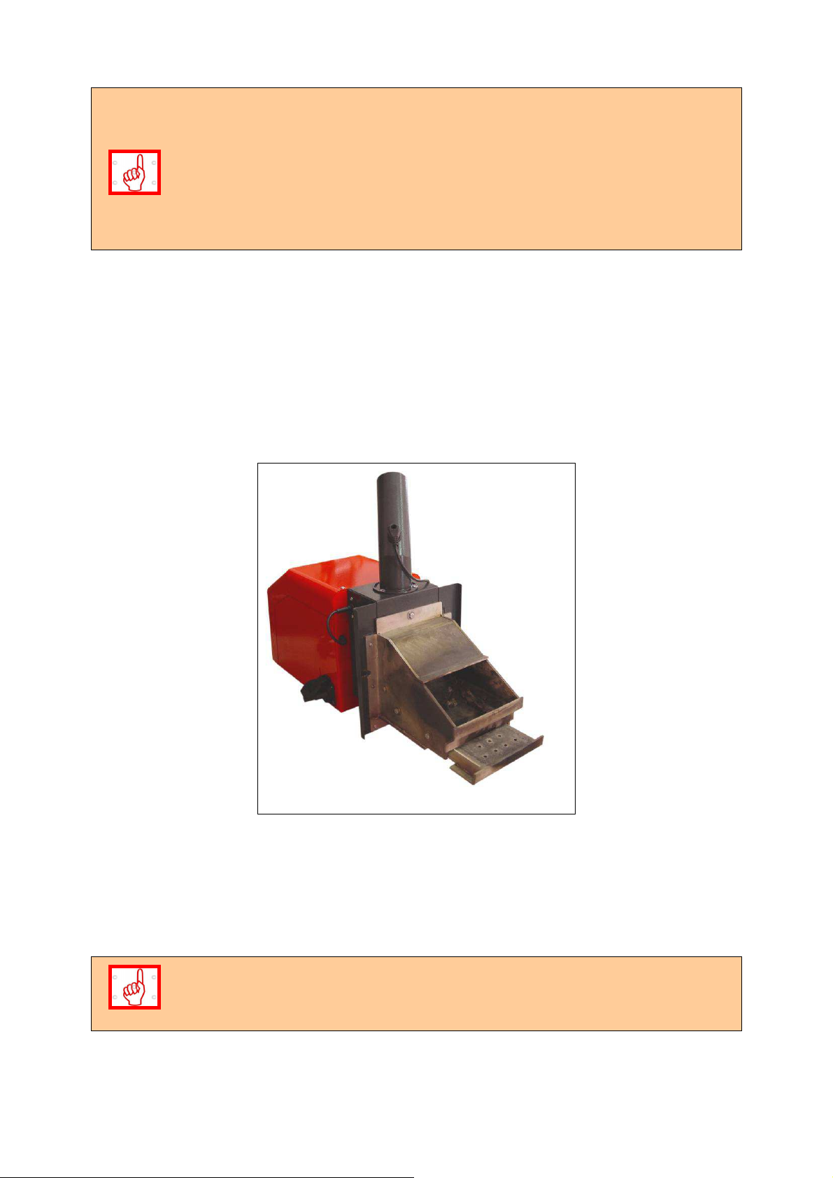
The automatic cleaning system of a pellet burner from series “GP xx sc” includes selfcleaning mechanism consisting of:
Moving grate mechanism;
Actuator that provides motion to the moving grate mechanism;
PC board that controls the actuator.
Figure 6.19. Self-cleaning mechanism of a pellet burner from series “GP xx sc”.
The automatic cleaning of the pellet burner is performed through a designed algorithm. It
activates when:
The burner has been started, after final combustion;
The burner has been stopped, including when the assigned circulations water
temperature has been reached;
The burner is normally operating, after defined intervals of time.
The adjustment of the automatic cleaning system of a pellet burner from series
“GP xx sc” must be performed by a certified staff.
Pellet burner GP xx sc 31
Page 32
The parameters: time between two cleaning procedures (“Max comb. Time”), number of
cleanings (“Iterations”) and other parameters, can be found in ”Advanced menu” (the
access is password protected). Example for typical settings:
Time between two cleanings (“Max comb. Time”) - 4 hours;
Number of cleanings (“Iterations”) - 2.
These settings should be changed when using fuels with higher ash content – the time
between two cleanings should be decreased.
6.10. USER INTRODUCTION WITH THE MAINTENANCE AND ADJUSTMENTS
PROCEDURES OF A PELLET BURNER FROM SERIES “GP XX SC”.
The users must read in details the presented manual book for operation of the burner, as
well as how it operates, the methods for adjustment of its heating output level and with the
methodic for maintenance.
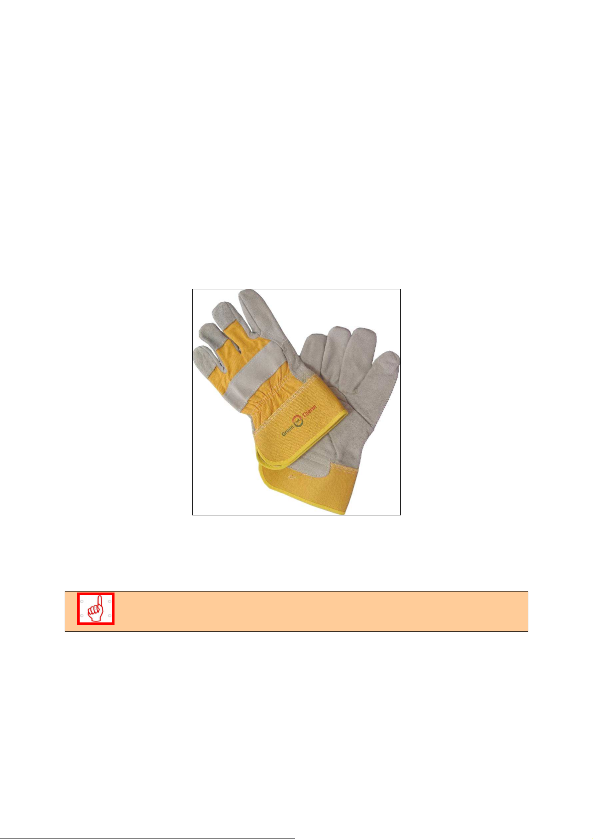
Figure 6.20. A pair of working gloves, provided by the manufacture company to the end
users, for easier and safe maintenance of the pellet burner.
It is necessary to clean the flexible connection tube from the dust separated by the fuel,
because when the auger transports fuel the dust from it gathers in the flexible pipe. As a
result the fuel feeding could be troubled and also the dust might fire in case of emergency
situation, in which the hot flue gasses are passing through the flexible tube.
Regular cleaning of the burner’s modules and components ensures it’s reliable
and economic operation for long time.
6.11. SAFETY AND UNPREDICTED RISKS.
RISKS RELATED WITH THE USAGE OF A PELLET BURNER FROM SERIES “GP xx
sc”.
The automated pellet burner from series “GP xx sc” is designed and manufactured in
compliance with the main safety requirements of the acting European standards and
provisions. Dangerous conditions might occur in the following situations:
The automated pellet burner from series “GP xx sc” has been used incorrectly;
Pellet burner GP xx sc 32
Page 33

The pellet burner has been installed by unqualified staff;
The guides for safe usage, presented in this manual book, have not been observed;
UNPREDICTED RISKS.
The automated pellet burner from series “GP xx sc” is designed and manufactured in
compliance with the acting safety standards. Although all possible risky situations are
preliminary considered, resulting from incorrect operation, the following risks might occur:
Risk from burning, caused by high temperatures from the burning process in the
combustion chamber;
Risk from electrical shock by indirect contact. The pellet burner is connected to the
power supply network and the controlling modules are positioned in specially
designed section, all equipped with the necessary components for overload and short
circuit protection. The ground connection of the burner is mandatory and must be
performed by an authorized technician. Opening of the protection cover panel of the
burner by unauthorized staff is forbidden;
Risk from fingers injuries during maintenance and cleaning. It is recommended to use
proper individual protection equipment;
Risk from strangulation in case of insufficient chimney draught to the consuming
appliance, to which the burner from series “GP xx sc” is mounted or bad sealing of
the flue extraction tract;
6.12. COMPLETION OF THE BURNER’S WARRANTY CARD.
The attached WARRANTY CARD must be completed by filling the required
information in its fields, as the signature and stamp fields must be completed too,
in order to ensure the WARRANTY CARD VALIDITY of the pellet burner from
series “GP xx sc”.
6.13. ACTIONS AFTER EXPIRY OF THE LIFE CYCLE OF A PELLET BURNER FROM
SERIES “GP XX SC”.
After expiry of the product’s life cycle, its termination must be environmentally friendly and
protective. For that purpose the burner has to be disassembled and its modules and
components have to be delivered to waste disposal offices, by observing the principles for
separate collection of wastes.
Pellet burner GP xx sc 33
Page 34

7. FAILURES AND TROUBLESHOOTING.
Table 7.1. Description of the failures in the operation of a pellet burner from series “GP xx sc”
and methods for troubleshooting.
Nо. FAILURE CAUSE TROUBLESHOOTING
1.
2.
3.
4.
5.
6.
7.
In case the burner is
mounted to a hot
water boiler and the
temperature in the
heated premises is
too low
In case the burner is
mounted to a hot
water boiler and the
temperature in the
heated premises is
too high
The burner is
switched ON but
there is no burning
process
Difficult pellets
ignition
The fuel ignition is
accompanied by
abnormal noise
Overheating of the
appliance, to which
the burner is
mounted
No fuel ignition No pellets in the fuel
Insufficient heating
output
The assigned
temperature is low
Low temperature
assignment by the
room thermostat (if
connected)
Heating output,
exceeding the
consumption
The assigned
temperature is high
High temperature
assignment by the
room thermostat (if
connected)
No assignment for
operation
The pellets are with
low quality
Insufficient chimney
draught
No heating load or
incorrectly adjusted
heating output level
of the burner, or of
the heat energy
consuming appliance
hopper
No pellets in the
burner’s combustion
chamber
Presence of nonignited or burned
pellets over the
burner’s fire-grate,
but there is no
burning process
It is necessary to adjust the burner’s heating
output level.
It is necessary to check the circulations water
temperature assignment in the burner’s control
module.
It is necessary to increase the room thermostat
temperature assignment.
It is necessary to increase the burner’s heating
output level.
It is necessary to decrease the assigned
temperature
It is necessary to decrease the room thermostat
temperature assignment
Check the assignment for operation by the
burner’s control module.
It is required to change the fuel, as its water
content is probably higher by the values needed
for normal operation of the appliance.
It is necessary to check the condition of the
chimney and of the appliance, to which the
burner is mounted and to clean the ash deposits.
After cleaning it might be necessary to adjust the
operational parameters of the system – ask for
servicing assistance.
Check the heating system - burner - appliance for
correct operation and eventually adjust the
operation parameters – to be performed by
servicing specialist.
After the consuming appliance cools down and
the failure has been removed deactivate the
emergency thermostat (unscrew the protection
cover cap, press the button and screw the cap
back), after that restart the burner.
The hopper from which the burner’s transport
auger intakes fuel must be refueled.
The process of primary fuel ignition can be
restored by restarting the pellet burner.
Clean the gathered fuel from the burner’s firegrate.
If the ignition heating element is damaged or
inactive it must be replaced.
Pellet burner GP xx sc 34
Page 35

Incorrect operation of
To be performed by servicing technician:
the burner’s photic
sensor, which
monitors the burning
process
The photic sensor for monitoring of the burning
process has to be re-adjusted or replaced – to be
performed by a servicing specialist.
8.
9.
10.
11.
12. Heating of the pellet
13. Heating of the pellet Low chimney draught Clean the appliance and eventually the chimney.
The burner does not
start or stops during
operation
The flame from the
burning process is
dim and the chimney
smokes too much.
The burner starts,
but can’t transit to
stable operation
mode
The burner operates
unstable
burner’s fuel feeding
inlet pipe
No power supply Check the operation of the burner’s display panel
and its indications.
Check the working order of the power supply of
the appliance, to which the burner is mounted
and which provides voltage with parameters
220V, 50Hz – to be performed by servicing
technician.
Check the burner’s electrical connections,
according to the attached wiring diagram. Check
for loose electrical connections – to be performed
by servicing technician.
No starting signal
submitted to the
burner
The burner does not
operate, although
there is starting
signal
Blown fuses
Pellets with low
quality
Improper adjustment
of the pellet burner’s
operational
parameters
Improperly oriented
photic sensor
The photic sensor’s
surface is dirty
The photic sensor
has defected – its
surface seems to be
burned
Malfunction of the
photic sensor
The control module’s
operational
parameters have
been changed
Insufficient chimney
draught or not
cleaned burner
Check if the burner receives starting signal and
the working orders of the electrical connections of
the burner’s module, which submits signal for
operation – to be performed by servicing
technician;
Check for loose electrical connections.
Check the working order of the burner’s control
module, which provides voltage with parameters
220V, 50Hz – to be performed by servicing
technician.
Check for activated alarm – check the list with
alarm codes in the controller and their indications,
as presented in the next table.
check the fuses condition and if necessary
replace them with new fuses, but only from the
same type.
Change the pellets as their water content is
probably higher than the required for normal
operation.
Re-adjust the burner’s operational parameters –
to be performed by a servicing specialist.
Change the photic sensor’s position for
monitoring of the burning process by turning it
around its longitudinal axis.
Clean the contaminations (dirt) from the photic
sensor carefully.
Replace the photic sensor with new one – ask for
servicing assistance.
Check the photic sensor’s working order
Check the burner’s heating output level
adjustment.
Check the controller’s adjustments – to be
performed by servicing technician.
Clean the appliance and eventually the chimney.
Possible solution is to install additional flue gas
extraction fan and/or to change the chimney*.
Pellet burner GP xx sc 35
Page 36

burner’s fuel feeding
inlet pipe and
activation of its
emergency
thermostat
14. High temperature
indicated by the
reversible
temperature sticker
15. Activation of the
irreversible
temperature sticker,
positioned on the
pellets inlet pipe of
the burner
16. Dirty and/or melted
photic sensor
17. Presence of
unburned fuel in the
ash tray
18.
19. A failure code,
20. The burner has
Too many slag
deposits in the
burner’s combustion
chamber (melted
mineral mass)
indicated on the
controller’s display
panel
stopped, but after a
new start it operates
again
or dirty appliance
from the ash
Increased resistance
in the flue extraction
tract or insufficient
chimney draught
Increase of the
operational
temperature in this
pipe, which in most
cases is caused by
hot gasses passing
through it
Improper stopping of
the burner’s
operation
Inefficient fuel
combustion
The used fuel is with
high ash content and
does not comply with
the requirements of
the appliance
The burner operates
in a mode with
heating output higher
than its nominal
output
Trouble in the
operation of the
burner
The photic sensor
submits faulty
information to the
controller
It is necessary to restart the burner. Possible
solution is to install additional flue gas extraction
fan and/or to change the chimney**.
It is necessary to clean the appliance and/or the
chimney from the ash residues. In case the
chimney draught is insufficient it is necessary to
install additional flue gas extraction fan and/or to
change the chimney - to be performed by
specialist.
It is necessary to clean the appliance from the
ash residues, to check and clean the chimney
tract and to check the pellet burner condition - to
be performed by specialist.
It is necessary to clean the photic sensor’s
surface or to replace it with new one. The
burner’s stopping procedure, as presented in this
manual book, must be observed.
It is necessary to adjust the appliance’s
operational parameters – ask authorized
servicing technicians for consultation and/or to
perform adjustments.
Change the fuel with type which complies with
the requirements for reliable operation of the
burner.
Decrease the heating output of the burner by
changing its output level.
Check the meaning of the indicated failure code
in the next table. If necessary look for
consultation/intervention by servicing technician.
Check the fuel quantity over the fire-grate. Look
for assistance or consultation by servicing
technician.
21. High temperature of
the flue gas (if a
thermometer is
installed)
22. Smoke in the boiler
room after a certain
period of operation
23. Another, not
described failures
Dirty heat
exchanging surfaces,
depending on the
consuming appliance
type and the
operation modes
Dirty or clogged from
dust flue extraction
tract of the heat
energy consuming
appliance
Ask for assistance by servicing specialist or
It is necessary to clean the appliance’s heat
exchanging surfaces.
Clean the heat energy consuming appliance from
the ash deposits.
company.
Pellet burner GP xx sc 36
Page 37

* The heating of the pellets inlet pipe in most cases is caused by
contamination of the heat exchanging surfaces of the appliance, to which
the pellet burner is mounted;
** In case of insufficient chimney draught it is recommended to look for
servicing assistance in order to solve the problem – cleaning or change of the
chimney might be required, as well as installation of additional flue extraction
fan or another solution.
Table 7.2. Description of the failures, saved in the “LOG” menu of the pellet burner’s from
series “GP xx sc” controller.
No.
1.
2.
3.
4.
5.
6.
FAILURE
CODE
10 Unsuccessful fuel ignition Clean the burner’s fire-grate.
11 The burner loses flame during
12 Failure in the photic sensor
13 The motherboard temperature is
14 The temperature sensor has
15 The temperature sensor has
FAULT DESCRIPTION TROUBLESHOOTING
Check for presence of fuel.
Look for consultation by servicing technician.
Look for servicing assistance.
operation
Look for servicing assistance.
operation
Switch the burner OFF and leave it to cool
too high
measured a value under 5oC
indicated a value over 120oC
down.
Look for servicing assistance.
The circulations water temperature is
dangerously low and can freeze.
Look for servicing assistance to check the
heating installation.
The circulations water temperature is
dangerously high. Overheating of the heating
system and the appliance might occur. Look
for servicing assistance to check the heating
installation.
7.
8.
9.
10.
11.
12.
13.
14.
16 Motherboard failure Look for servicing assistance.
18 The fan’s relay is out of order Look for servicing assistance.
19 The fan is not rotating Look for servicing assistance.
20 The fan is not rotating with the
required speed
21 Primary ignition failed Check for presence of fuel in the hopper and
22 Failure of the external auger Look for servicing assistance.
23 The photic sensor does not
darkens during the final
combustion phase
24 The photic sensor loses light
during operation and
unsuccessful firing after the
ignition phase
Look for servicing assistance.
check the auger’s operation.
Look for servicing assistance.
Look for servicing assistance.
Look for servicing assistance.
Pellet burner GP xx sc 37
Page 38

Table 7.3. Description of the failures indicated on the display panel of the pellet burner from
series “GP xx sc”.
MESSAGE INDICATED
No.
1. IGNITION FAILED Ignition failure Check for presence of fuel and also the
2.
3.
4.
5.
6.
ON THE DISPLAY
PANEL
LOST FIRE IN
COMBUSTION
STOKER FAULT The auger connection
TEMP- SENSOR LOW The temperature
PHOTOSENS Photic sensor failure Check the photic sensor condition, replace it
TEMP SENSOR
OVERHEAT
MEANING
Loses flame during
burning
is interrupted
sensor is switched
OFF
High temperature
indicated by the
temperature sensor
TROUBLESHOOTING
auger’s operation.
If there is fuel - look for servicing assistance.
Check the auger’s connection, restart the
burner.
Check the auger’s power supply. Power
supply cut off might occur if the pellets inlet
pipe has been overheated – check the
temperature stickers.
Check connection of NTC sensor.
if necessary – to be performed by a servicing
technician.
Check the hot water boiler’s condition, cool
the appliance down.
8. WIRING DIAGRAM OF AN AUTOMATED PELLET BURNER“GP XX SC”.
The connectors and the NTC sensor are installed in the hot water boiler.
TD – thermo-disc (installed on the pellet burner’s fuel inlet pipe) - 950C.
Remove the connector’s bridge connection when using a room thermostat.
Use the room thermostat’s socket only. Do not supply external voltage!
See the wiring diagram!
Figure 8.1. Wiring diagram of a pellet burner from series “GP xx sc”.
Pellet burner GP xx sc 38
Page 39
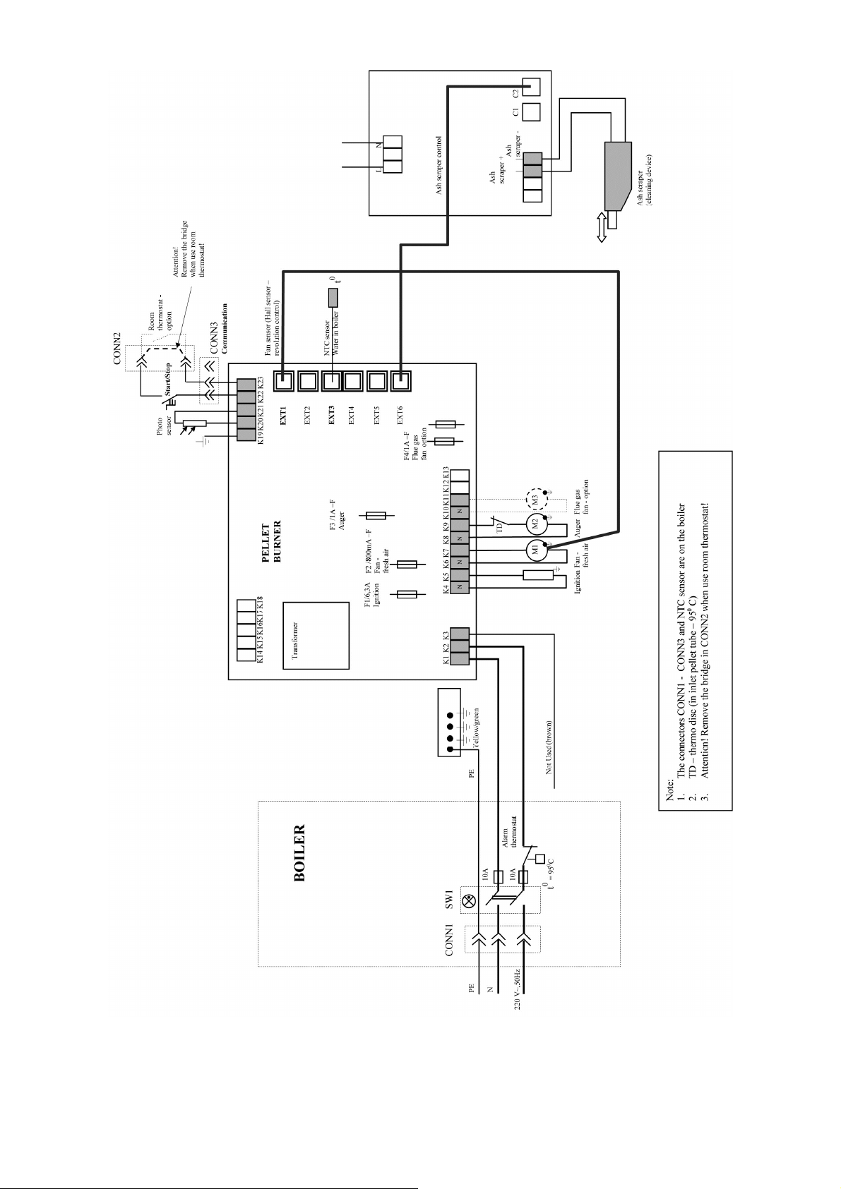
Pellet burner GP xx sc 39
Page 40

The manufacture company guarantees correct and failsafe operation of a pellet burner from
series “GP xx sc”, only when the requirements for installation and operation are observed
during initialization to operation and maintenance.
The warranty start date of the automated pellet burner from series “GP xx sc” is considered
from the date of completion and stamping of its warranty card.
The pellet burner’s warranty start date is considered from the date of its initiation to
operation, but no later than 6 months from the date of purchase.
The warranty period validity of the pellet burner is 24 (twenty four) months.
The warranty is valid only if an invoice and original warranty card have been presented.
THE WARRANTY OF THE PRODUCT IS INVALID in the following cases:
Damages of the pellet burner caused by improper storage, transport and/or
unloading, not performed by the manufacturing company;
Emergencies caused by natural disasters (earthquakes, fire, floods and etc.);
The requirements for installation, operation and periodical maintenance,
presented in the present manual book, are not observed;
Attempts to recover defects, performed by the buyer or by other unauthorized
persons;
Changes in the pellet burner’s modules construction;
Incorrect technical project for installation and operation of the burner;
Damages or failures caused by reasons for which the manufacture company is
not responsible or can’t perform control;
Interferences and failures not caused by the pellet burner from series “GP xx sc”,
but have led to failures/damages in its construction;
If the irreversible temperature sticker has been colored (activated) or in case it
has been removed, torn, detached or destroyed.
Every warranty repair must be registered in the product’s warranty card.
The warranty period is stopped for a term considered from the date of a registered warranty
claim until the date of removing the failure.
WARRANTY CONDITIONS
Pellet burner GP xx sc 40
 Loading...