

GreenEcoTherm GP IV Series, GP 32 IV, GP 25 IV Installation And Operation Manual
MANUAL
for installation and operation of
automatic pellet burner of series
“GP IV”
http:// www.greenecotherm.eu

(
Version
:
20.2.2015 г. 14:04
)
Producer
Address
Phone
Fax
e-mail
Web site
Ekoterm Proekt EAD
Bulgaria, Haskovo 6300, “Saedinenie” 67 blvd.
+359 800 15 145
+359 38 603045
sales@ecotherm.bg
www.ecotherm.bg
Thank You for buying our product – automatic pellet burner of series „GP”. This manual will
help You to use and maintain the unit properly.
NOTE : in this manual is used the symbol “GP” for the entire range of pellet burner, which
includes the models “GP25 IV” and “GP32 IV”. The automatic pellet burners of series “GP
IV” are modification of the well-known pellet burners of series “GP”. In the manual, however
will be used a common symbol “GP”.
ATTENTION!
IN INTEREST OF YOUR PERSONAL SECURITY IT IS NECESSARY TO
READ THOROUGHLY AND CAREFULLY THIS INSTRUCTION MANUAL
BEFORE PROCEEDING WITH ANY ACTIONS WITH THE BURNER –
INSTALLATING, CONNECTING, OPERATING, ETC. IN CASE THAT
REQUIREMENTS, DEPICTED IN THIS MANUAL ARE NOT SATISFIED,
FAILURE OF THE UNIT COULD BE EXPECTED, OR EVEN FATAL
CONSEQUENCES, FOR WHICH THE PRODUCER COMPANY DOES NOT TAKE
RESPONSIBILITY.
Instruction manual for installation and operation of automatic pellet burner of series “GP IV”
p. 2/48

Table of contents
Page
1. Automatic pellet burner of series “GP” – description and advantages .................................................. 4
2. Automatic pellet burner of series “GP” technical data ............................................................................ 6
3. Description of the construction of pellet burner of series “GP” .............................................................. 9
3.1. Main properties .................................................................................................................................. 9
3.2. Specific design measures in order to increase the safety operation of the burner ..................... 12
4. Installation of automatic pellet burner .................................................................................................... 14
4.1. Some basic requirements for correct installation of automatic pellet burner of series “GP” : . 14
4.2. Installation of the burner ................................................................................................................ 14
4.3. Overall and attachment dimensions of the burner’s main unit ................................................... 14
4.4. Arrangement and installation of the pellet burner’s modules ..................................................... 17
4.5. Information, considering the installation of the automatic pellet burner of series “GP” and its
operation with hot water boilers. .................................................................................................................. 18
5. Initial steps and starting of pellet burner of series “GP” ....................................................................... 20
5.1. Basic fuel requirements ................................................................................................................... 20
5.2. Staring automatic pellet burner of series “GP” ............................................................................ 20
5.2.1. Interface control board of pellet burner of series “GP IV” ................................................ 21
5.2.2. Automatic pellet burner electrical power supply ................................................................. 21
5.2.3. Switching ON the burner of series “GP” .............................................................................. 21
5.2.4. Burner’s operating algorithm ................................................................................................ 22
5.2.5. Operating control parameters of the burner of series “GP” .............................................. 24
5.2.6. Description of the initial menu, the starting process and the adjustment of the control
module of pellet burner of series “GP IV” .............................................................................................. 24
5.2.7. Adjustment of the pellet burner, according to the heat consumption rate ........................ 27
5.2.8. Nominal operating mode of the burner ................................................................................ 27
5.2.8.1. Operating mode of the burner of series “GP IV” ........................................................... 28
5.2.8.2. User menu items of the control module of pellet burner of series “GP IV” ................. 29
5.2.9. User menu items in control module of automatic pellet burner of series “GP IV” .......... 29
5.2.9.1. Menu item „EFFECT LEVEL” ........................................................................................ 29
5.3. Adjustment of the thermal capacity of the burner ........................................................................ 31
5.3.1. Decreasing the thermal capacity of the pellet burner.......................................................... 31
5.3.2. Increasing the thermal capacity of the pellet burner .......................................................... 31
5.4. Stopping the operating mode of the burner of series “GP IV” .................................................... 32
5.4.1. Stopping the operating mode of the pellet burner of series “GP IV” by switching OFF the
“START” switch ............................................................................................................................................. 32
5.4.2. Stopping the operating mode of the pellet burner of series “GP IV” by setting the menu item
of its control module. ...................................................................................................................................... 32
5.5. Turning OFF the automatic pellet burner of series “GP IV” by external for the burner control
module 34
5.6. Menu item, indicating list of the latest 10 errors, arose from the operation of the pellet burner
of series „GP IV” ............................................................................................................................................ 35
5.7. Restarting the operation of a pellet burner of series “GP” .......................................................... 35
5.8. Description of the active thermo stickers, showing the condition of the system ......................... 36
5.9. Removal and attachment of the burner’s grate at maintenance and cleaning procedure of the
pellet burner of series “GP” .......................................................................................................................... 37
5.10. Showing and teaching the end user about the maintenance and adjustment procedures of
the burner 40
5.11. Safety and unexpected risks ....................................................................................................... 41
5.12. Operation faults and repairing procedures .............................................................................. 42
5.13. Automatic pellet burner of series “GP” warranty form completion. ..................................... 46
5.14. Actions, after the burner is not in exploitation anymore (recycling). ..................................... 46
6. Electrical scheme of automatic pellet burner of series “GP IV” ........................................................... 47
WARRANTY CONDITIONS ............................................................................................................................ 47
p. 3/48

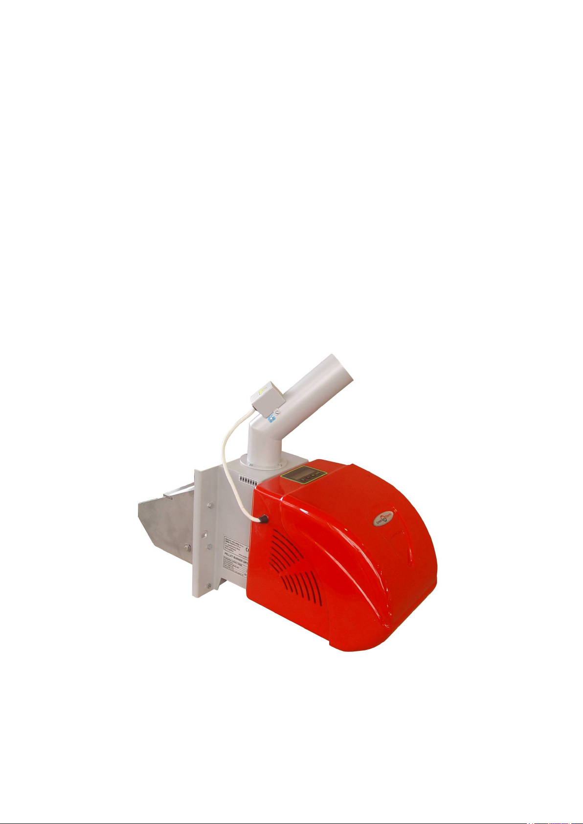
1. Automatic pellet burner of series “GP” – description and advantages
“GP” is automatic pellet burner, which utilizes wood pellets. The burner is designed to be
installed on already installed heating boilers or other equipment, thus allowing fuel switch
procedure to a renewable energy sources - biomass. The installed burner operates on wood
pellets and the thermal energy, resulting from the optimized combustion process is
directed to the heat exchange surfaces of a boiler or another thermal consumer.
The kit of the pellet burner of series “GP” consists of:
Main module with detachable grate – 1 sp.;
Fuel transport auger – 1 sp.;
Flexible hose– 1sp. with fixing brackets – 2sp.;
Pair of working gloves – 1sp.;
User manual – 1sp.;
Transport package of the main module – 1sp.;
Transport package of the transport auger – 1sp.;
The burner could utilize following types of fuel
Wood pellets, class ENplus-A1;
Wood pellets, having diameter 6 and 8 mm, categorized in the range of: A, AB, B
(according to the methodology, developed for pellets properties estimation in pellet
burner producer company);
Pre-dried pits (from cherries for example);
Fuel mixture – pellets and pits (for example mixture ratio could be 50% - 50%);
Other solid biomass based pellets, but these fuels need testing and approval in
pellet burner producer company laboratory;
The unit is equipped with
microprocessor module, which controls the functions of the unit and is adjustable
to the specific needs of a heating system;
integrated display and keyboard, which indicates the operating mode of the burner,
the keyboard is used to make changes of the values of the operating parameters;
auger, which transports fuel from a bunker to the main unit;
fresh air supplying fan, equipped with a Hall sensor, which returns information to
the control unit;
electric heater, which ignites the fuel;
combustion chamber, which gives environment for efficient combustion process;
removable grate of the combustion chamber, allowing easy access and ash
cleaning;
photosensor, which gives information for the status of the combustion process to
the control unit and allows dynamic operation of the burner;
reversible thermo sticker, indicating the operating mode of the system and the
requirement of ash deposition cleaning of the appliance and/or the flue stack;
irreversible thermosticker, indicating alarm overheating of the burner, which could
precondition act of no-warranty service of the unit;
The burner is equipped with
automatic fuel ignition system;
automatic fuel transport system – from bunker to the combustion chamber of the main
unit;
p. 4/48

safety system, which blocks its operation in case that at any circumstances the fuel
delivery pipe is preheated above certain temperature safety level;
photosensor, which allows dynamic monitoring of the combustion process status;
transition system, which modulated the air supply fan operation at ignition process;
thermal capacity modulating system, which controls both the air supply fan operation
as well as the fuel dozing in order to obtain optimal operation and low fuel
consumption;
the control module could periodically perform procedure of final combustion and air
driven grate de-ashing of the burner and will continue operation with new fuel
ignition;
Advantages of the burner
the burner automatically utilizes renewable energy source – biomass, which makes it
environmental friendly and does not contribute to the global warming and pollution;
the burner is installed in order to apply the so called “fuel switch process” for
appliances, utilizing fossil fuels – diesel, natural gas, LPG, coal;
the burner’s design allows easy installation on manual fed boilers – such as those,
designed for coal, wood logs. The heating system and the boiler/equipment however
need minor redesign and reconstruction in order to allow such fuel switch process;
the resulting heat energy, based on organized combustion process of renewable energy
source - biomass, is less influenced by the global trend of the energy sources and as
result the price is competitive, compared to price of the popular energy sources;
the burner operates automatically and achieves operation comfort, delivered by
operating of fossil fuel burners – working with liquid and gaseous fuel, which permits
remote control by programmable room thermostat;
the burner’s control module performs automatic fuel ignition procedure;
automatic operation of the burner, which allow variable thermal capacity operation,
operation with standard room thermostat (or weekly programmable thermostat), which
allows maximal thermal comfort and optimized fuel consumption;
modulation of the operating process, which allows optimal working conditions and
sustaining high combustion efficiency;
the modulation of the controlled combustion process allows intensified technical work
at installation and simplified adjustment;
simplified installation procedure and initial adjustment, which guarantees faster
assembly and unified approach;
opportunity to utilize biomass, pellet shaped as well as other dried nuts, according the
appropriate fuel table;
high efficiency;
low pollutant emissions;
automatic fuel transport from a bunker, built according to the local units arrangement
and need of the client (the bunker is not part of the burner equipment delivery);
simplified maintenance and service;
minimal operating costs;
p. 5/48

2. Automatic pellet burner of series “GP” technical data
2.1. Thermal and technical data of automatic pellet burner of series “GP”, utilizing wood
pellets are given in Table 2.1;
2.2. Dimensions and technical data of automatic pellet burner of series “GP” are given in
Table 2.2;
2.3. Recommended solid biomass fuel properties – wood pellets, are given in Table 2.3;
2.4. Pellets classification, considering their physical properties (based on fuel proximate
analysis) are shown in Table 2.4;
2.5. The European standard for wood pellets ENplus is shown on Table 2.5;
Parameter Dimension Value
Model
Nominal thermal capacity kW 25 32
Thermal capacity operation range kW 7 – 25 10 – 32
Utilized solid fuel
Pre-dried cherry nuts;
Other dried nuts;
Utilized wood pellets, complying ENplus ENplus-A1*
Utilized pellets, complying pellet burner producer
classification methodology
Wood pellets fuel consumption rate at nominal
thermal capacity
Fresh air flow rate, required for effective
combustion process and boiler operation
- GP 25 IV GP 32 IV
Wood pellets;
A, AB, B*
kg/h
kg/h
m3/h
5.3 6.8
45 – 50 57 – 64
39 – 44 50 – 56
Averaged wood pellets consumption rate (the unit
is operating in a popular heating system)
Air excess ratio λ 1.5 – 1.6
Solid fuel residue ash The quantity depends on
Table 2.1 Thermal and technical data of automatic pellet burner “GP”, utilizing wood pellets;
* EXPLANATION : the automatic pellet burner of series “GP” is designed to utilize wood
pellets, which have properties, defined in the referred ENplus norm. As an temporal exception
(for several hours) it is allowed to utilize pellets, which are not covering the required class of
the fuel, practically in such cases the fuel has low quality and high ash content, which leads
to more frequent ash residue cleaning of the burner’s grate, as well as the heat exchanger’s
walls;
kg/h
3.6 4.7
the ash contents in the
raw fuel, as well as
operating conditions
p. 6/48
Parameter Dimension Value
Type
- GP 25 IV GP 32 IV
main module kg 14.9 14.9
Weight
Overall dimension of the
unit (WxDxH)
fuel transport
auger
kg 12 12
main module mm 270 х 630х 500
fuel transport
auger
mm 220x1520x110 220x1520x110
Power supply - 1PEN ; 50Hz; 230V;
Power consumption rate
at nominal
load
A
0.2 0.2
at ignition A 4.5 4.5
Electrical capacity VA <100 + 1100 (at ignition process)
Electric protection - IP20
Table 2.2 Dimensions and technical data of automatic pellet burner “GP IV”
Parameter Dimension Value
Pellet’s characteristic size mm 6 – 8
Recommended fuel net calorific value MJ/kg >17.2
kWh/kg >4.7
Class of wood pellets (ENplus) ENplus-A1
Wood pellets category A, AB, B*
Ash content % See Table 2.4.
Moisture content % Max. 8 – 10%
Table 2.3 Recommended solid biomass fuel properties – wood pellets
* See the notes above;
Classification of wood pellets, considering their physical properties (based on fuel proximate
analysis) – according to fuel evaluation method, developed and applied in pellet burner
producer company is show on the following table.
Pellet’s category Ad DU
A
AB
B
BC
C
CD
D
DE
E
EF
d
A
d
A
d
A
d
A
%6.0
%6.0
%0.3
%0.3
%0.16.0 dA
%0.16.0 dA
%0.2%0.1 dA
%0.2%0.1 dA
%0.3%0.2 dA
%0.3%0.2 dA
DU
DU
DU
DU
DU
DU
DU
DU
DU
DU
%0.97
%0.97
%0.97
%0.97
%0.97
%0.97
%0.97
%0.97
%0.97
%0.97
Table 2.4. Pellets classification, considering their physical properties
where :
p. 7/48

Ad – ash contents, dry basis, [%];
1
)
3)
4)
4)
2)
2)
2)
2)
2)
2)
2)
2)
2)
2)
2)
DU – mechanical durability, [%];
The approval of the new EU standard for wood pellets (EN 14961-2)
was at mid 2010 and introduces new certificates ENplus for pellets,
utilized in domestic heating appliances, the certificate EN-B is applied
for industrial boilers. The standard ENplus defines classes of the wood
pellets, which could be considered as qualifications: А1 and А2. The
class А1 introduces the most stringent limits for the ash content in the
wood pellets. The class А2 defines ash content up to 1.5%. For
industrial applications the wood pellets should cover the requirements of the certificate EN-B,
which is less stringent, that the previous and the generally the quality of the pellets is lower.
Parameter
Dimension
ENplus-A1
ENplus-A2
Diameter mm 6 (± 1) 6 (± 1)
Length mm 3,15 ≤ L ≤ 40
3,15 ≤ L ≤ 40 1)
Bulk density kg/m³ ≥ 600 ≥ 600
Calorific value MJ/kg ≥ 16.5 ≥ 16.5
Moisture % ≤ 10 ≤ 10
Dust % ≤ 13) ≤ 1
Mechanical durability % ≥ 97.5
≥ 97.5
Ash % 2) ≤ 0,7 ≤ 1.5
Ash melting temperature °C ≥ 1200 ≥ 1100
Chlorine %
Sulphur %
Nitrogen %
Copper mg/kg
Chromium mg/kg
Arsenic mg/kg
Cadmium mg/kg
Mercury mg/kg
Lead mg/kg
Nickel mg/kg
Zink mg/kg
≤ 0.02 ≤ 0.03
≤ 0.05 ≤ 0.05
≤ 0.3 ≤ 0.5
≤ 10 ≤ 10
≤ 10 ≤ 10
≤ 1 ≤ 1
≤ 0.5 ≤ 0.5
≤ 0.1 ≤ 0.1
≤ 10 ≤ 10
≤ 10 ≤ 10
≤ 100 ≤ 100
1) no more that 1% of the wood pellets could be longer that 40 mm, the max. length is 45mm;
2) determined on dry basis;
3) particles <3.15 mm, fine dust particles, before fuel delivery;
4) for measurements, performed with Lignotester the limit value ≥ 97.7 weight based %;
Table 2.5 European standard for wood pellets ENplus;
p. 8/48

3. Description of the construction of pellet burner of series “GP”
3.1. Main properties
The pellet burner of series “GP” consists of the following elements/modules:
The basis part of the pellet burner is the main unit, which consists of:
Combustion chamber, which forms combustion domain and optimal environment for
solid biomass combustion, is designed of high quality stainless steel;
Grate of the combustion chamber, which could be easily detached and
reveals access for ash removal;
Air duct, which uniformly distributes the airflow and ensures safe cooling of
the elements of the burner;
Electric heater, which heats and ignites the fuel. The heater is positioned
beneath the inclined plate of the grate in the combustion chamber;
Air supply fan, equipped with Hall sensor for rotation speed monitoring;
Photosensor, which monitors the intensity/presence of the combustion
process, installed aside of the combustion chamber for easy access and cleaning;
Alarm thermo-probe, which stops and blocks burner operation in case of
“back fire” process in the fuel delivery pipe;
Control board, which monitors and controls the operation of the burner and
indicates its status;
LCD display and integrated keyboard, used to change the values of the
operating parameters as well as adjustment of the thermal capacity of the burner;
Transport auger connector, which realizes power supply to the electric motor
of the auger;
Reversible liquid crystal thermo sticker, which indicates the operating
temperature of the burner’s main body at the spot of the sticker. This thermometer
should be used to estimate the real condition of the appliance as well as the flue stack
draught and the requirement for ash deposition cleaning;
Irreversible thermosticker, which indicates any overheating of the fuel delivery pipe,
preconditioning no-warranty servicing of the burner’s main module and any damages
of the fuel supply hose;
Electrically driven (external for the main unit) fuel transport auger, which extracts
the solid fuel from the bunker and delivers pellets to the main unit, according to the
operating mode of the burner. The transport auger consists of electric gear-motor, a
transport pipe with one end in the fuel hopper and the other end is side opened and
delivers fuel to the main unit through a aperture;
Flexible hose, which is made of specific semitransparent thermal resistant material (in
case of combustion it does not emit toxic substances and does not sustain combustion
process), which connects the transport auger and the main module;
p. 9/48
(display + keyboard)
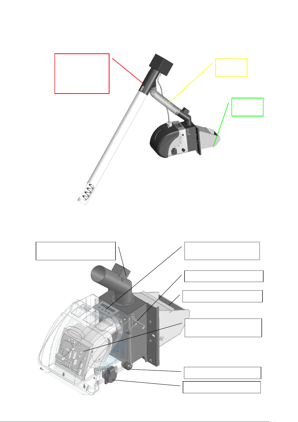
The main modules of the pellet burner and their arrangement are shown of the following
figure.
Fuel transport
auger (from the
bunker to the main
Flexible
pipe
unit)
Main unit
Figure 3.1 Arrangement of the modules of the pellet burner of series “GP IV” (side view);
Elements and modules of the main unit of the pellet burner of series “GP IV” are shown on
figure 3.2 and figure 3.3.
“Back fire” safety alarm
thermo-probe
Interface panel
p. 10/48
Figure 3.2 Section view of
Photosensor
the elements of the main
unit of the burner of series
Combustion chamber
“GP IV”;
Control board of the burner
Power supply cable
Auger power supply plug

Fuel delivery pipe and
“back fire” safety
thermo-probe
Installation flange for
attaching the main module
to a consumer unit
Grate of the combustion
chamber
Figure 3.3 Side view of the main unit of the pellet burner of series “GP IV”;
Irreversible
thermo sticker
Reversible
luquid crystal
sticker
Figure 3.4. View of the side of the burner with attached liquid crystal thermo sticker;
COMMENTS :
Reversible liquid crystal thermo sticker indicates the operating temperature of the
spot around the sticker. This temperature is indicative for the operating mode of the
pellet burner and the hydraulic losses of the flue gases, passing through the heating
appliance to the flue stack. The initial condition of the thermo-sticker is indicated with
black color of all thermo active segments. In case of temperature rise, the segments
are sequentially getting light colored, according to the temperature range of any
individual thermo-active segments. However, the increased temperature in this zone of
the burner is indicator for the requirement for planning of ash cleaning procedure of
the heating appliance and/or the chimney. At cooling down the main body of the
burner, the reversible sticker gets into its initial condition (all segments are dark);
p. 11/48
Irreversible liquid crystal thermo sticker is indicator for at least one event of
overheating the pellet supply pipe of the main body of the burner. This sticker changes
its color irreversibly. Initially the color of this sticker is white, at activation the
sensing segment gets dark irreversibly;
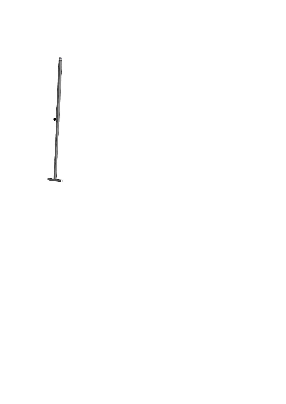
In case the fuel transport auger should be supported, then an option should
be utilized – a telescopic support, which could support the weight of the
auger and the length could be adjusted in order to achieve the required
installation angle and the overall stability of the auger.
Figure 3.5. Side view of the auger support telescopic element – option of
the kit of the pellet burner of series “GP”;
3.2. Specific design measures in order to increase the safety
operation of the burner
The ignition and the combustion process is monitored by microprocessor control
board;
The ignition process is monitored and in case that the fuel is not ignited for some
reason, after certain number of ignition trials, the operation of the burner is stopped
and alarm mode is indicated;
In case that fuel is consumed from the hopper, than after the defined number of
ignition trials the burner will go out in stop mode and alarm is indicated as well;
The flexible hose, which connects the fuel transport auger with the main unit, is
transparent and is made of specific heat resistant material;
Information stickers are applied, indicating certain precautions measures and correct
operation of the unit;
The burner is equipped with safety elements, which are involved in „back fire”
protection system:
p. 12/48
o Free falling duct, which practically interrupts the fuel flow between the
transport auger and the main module. This duct is approximately 250mm long.
Beside that, the fuel auger is connected to the main unit by a flexible hose,
which does not contain fuel. The grate of the burner is however charged with
controlled amount of fuel, which is utilized at the combustion process and
possibility of back fire is strongly reduced;
o Sensor of “back fire” alarm thermo-probe, which is positioned on the fuel
delivery pipe of the main unit, activates at surface temperature levels above 90
– 95oC. In case of alarm thermo-probe activation, the main unit and the fuel
transport auger are stopped and switched to alarm mode. This mode is
indicated by appropriate message, shown on the display - „STOCKER
FAULT”. The alarm mode is not automatically deactivated and needs manual

restarting. The cause of the alarm situation should be clarified and precaution
measures should be taken before restarting the burner (performed by switching
OFF and back ON the main power supply of the burner);
o Reversible liquid crystal thermo sticker, which shows the operating
temperature in the zone around the sticker, considered as characteristic for the
condition of the burner and the heating system in total. In indirectly indicates
the need for ash deposition cleaning of the heating appliance as well as the
chimney;
p. 13/48

4. Installation of automatic pellet burner
Requirements and recommendations.
4.1. Some basic requirements for correct installation of automatic pellet burner of
series “GP” :
The burner should be positioned in order to guarantee comfort maintenance and easy
access for cleaning procedures;
The main unit of the burner should be installed on a unit (a boiler, heat consumer,
etc.), which has the appropriate thermal capacity, at least equal that of the burner and
should provide easy access for burner’s grate cleaning and ash removal;
It is strongly forbidden to install the burner in dwellings, including corridors;
The installation process of the burner, its attachment and connection of the power
supply and control should be performed by authorized personal only;
Installation and maintenance of the burner is performed by specialized trained
personal of authorized companies;
Connection of the burner to the power supply and the control board should be
performed by authorized technician only;
Before starting the burner, the heat consumer unit (at which the burner is attached)
should be thoroughly checked in order to guarantee safe operation of the system;
The maintenance of the burner should be performed by adult person, who is familiar
with the safety procedures and the user manual of the appliance;
ATTENTION : the mounting of the main module of the pellet burner of series “GP” to a
heating appliance (in most of the cases – hot water boiler) is made by screws and
corresponding nuts. It is necessary to tighten the main module of the burner to the appliance
by a tool (wrench). It is not permissible to attach the burner to an appliance by handles,
which could allow detachment of the main module by hand. The installation process of the
burner should be performed by authorized trained technician only, using a tool;
4.2. Installation of the burner
The installation process of the burner should be based on authorized project,
which governs the requirements of acting norms and recommendations.
In case that the heat consumer unit is solid fuel hot water boiler, that the requirements
are depicted in norm EN 303-5/2000 - „Heating boilers. Part 5 : Heating boilers for
solid fuels, hand and automatically fired, nominal heat output of up to 300 kW.
Terminology, requirements, testing and marking”;
In case that the heat consumer is not hot water boiler, than appropriate norm and
requirements should be governed at preparing the installation project;
Fire safety requirements;
To the power supply - EN 60335-1/1997 - “Household and similar electrical
appliances – safety. Part 1. General requirements”;
4.3. Overall and attachment dimensions of the burner’s main unit
The installation process of the burner should consider the requirements, described
above, as well the dimensions of the unit, shown on the following figures.
p. 14/48
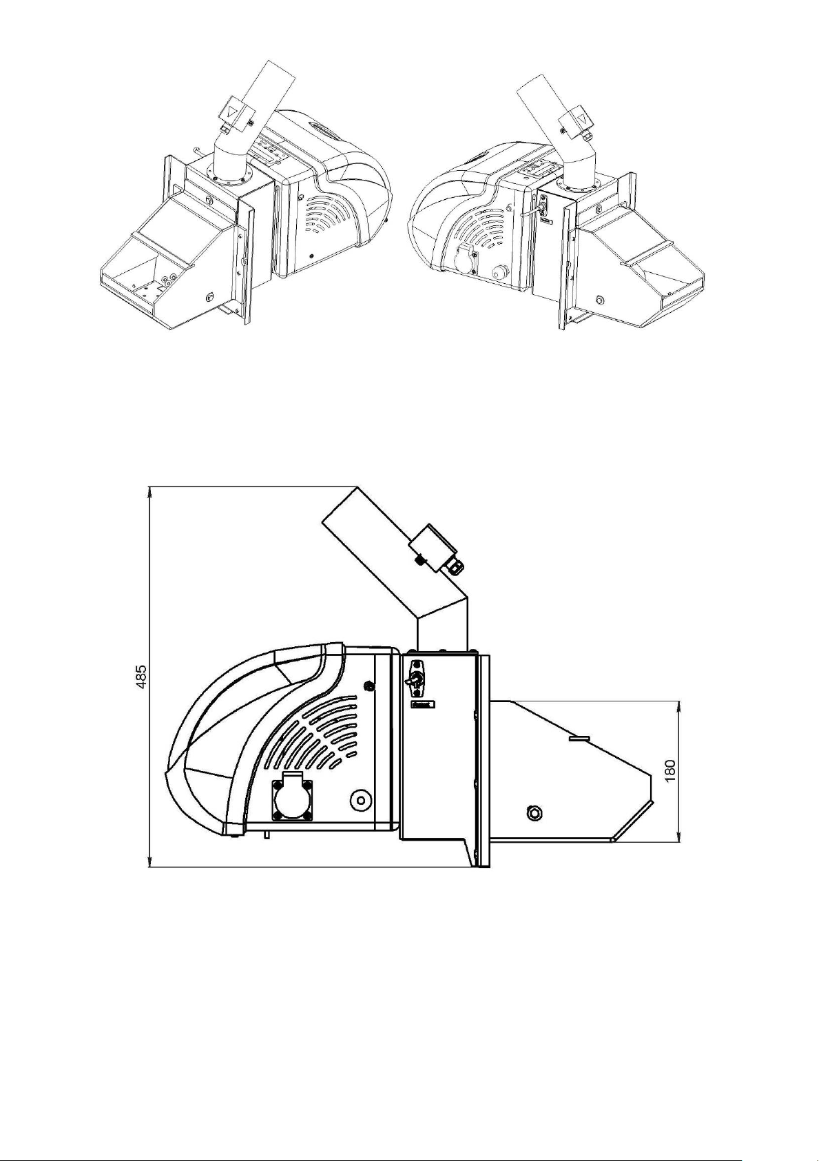
Figure 4.1. Isometric view of the main unit of the pellet burner of series “GP IV”– side
views;
Figures 4.2, 4.3. and 4.4. show the overall and detailed dimensions of the main unit of
the burner, which should be considered at preparing a project and installation of the
appliance.
Figure 4.2. Overall and characteristic dimensions of the main unit – side view;
p. 15/48
 Loading...