

Green Eco Pro Ultra 90 Instruction Manual
Model:
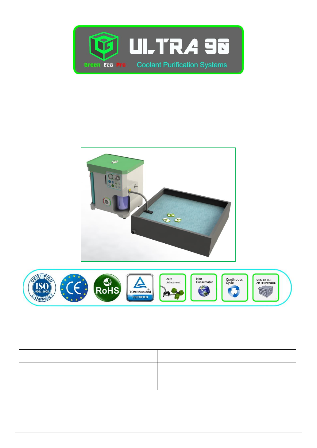
Ultra 90
Serial No.
Manufacture Date:
Coolant Purification Systems
Ultra 90
INSTRUCTION MANUAL
Revision: E
September 2016
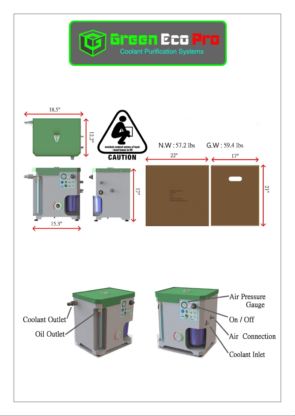
Unit Foot Print & Layout
Description of each components
Installation Guide
Before starting this installation, carefully unpack and clean all unit elements. For
proper part identification and location, it will be most helpful to study the assembly
and parts instructions included in this document.
Important
DO NOT CONNECT TO AN AIR SUPPLY THAT EXCEEDS 145 P.S.I. ( 10 Bar )
• Disconnect air supply and depressurize all air lines.
• After installation, air and coolant systems should be connected and fully tested for proper
function and leaks.
• Please follow the manufacturer’s safety guidelines for all power and hand tools used for this
installation.
• Installation of this system on any machine other than those listed, voids any and all
intended warranties and liabilities by Green Eco Pro Co.
TOOLS REQUIRED: The installation of this machine can be accomplished with basic
machine service tools
Special Tooling: None

Installation Guide – Page 1
1” coolant return hose
Hose Clamps
Filter Wrench
Coolant Float
Inlet unit
Main unit
Filter element
1. Please verify all peripheral accessories.
2. An instruction of installation procedure
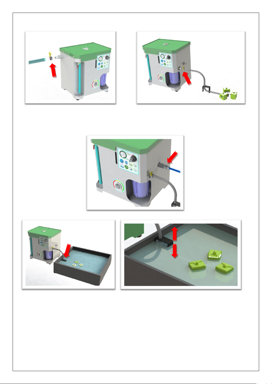
1.1Install the filter element, be sure to retain the O-ring
Installation Guide – Page 2
2.1 Connect the 1” Coolant return
using the large hose clamp.
3.1 Connect the Coolant Inlet hose to the
hose to Coolant Outlet port by
Coolant Inlet port using small hose clamp
4. 1 Connect Air supply hose
5. 1The bracket that holds the float tubes must attach on the edge of coolant tank, in
order to keep it away from the existing chips or debris. If there are any
suspended solids or floating debris on the surface of the coolant, be sure to
remove them before operating the unit.
6. 1The Float Tube Inlet must face in the upward position.
7. 1In order to keep the Inlet on the surface of coolant, adjust the bracket that retains
the float inlet accordingly to an appropriate position.
To keep the float tubes balanced, the coolant level must be maintained above 2” if
required, please add coolant.
 Loading...