

Greenco 1RV0020, 1RV0063, 1RV0025, 1RV0040, 1RV0100 Operating Instruction
Ii
Operating Instruction
Rotary Vane Vacuum Pump
Manufacturer
Zhejiang Greenco Industry Co Ltd
lEEN[O
1 RV0160
1RV0020/1RV0025/1RV0040/1RV0063/1RV0100
11
RV0200
11
RV0250
11
RV0300
CE

Table of Contents
Preface ................................................................................... 1
Technical data ........................................................................ 2
Principle of operation . ......................................................... 3
Oil Circulation ...................................................................... 3
Cooling ................................................................................ 3
On/Off switch ....................................................................... 3
Safety...................................................................................... 3
Intended use ....................................................................... 3
Safety notes ........................................................................ 3
Emission of Oil Mist ............................................................. 4
Noise ................................................................................... 4
Transport ................................................................................ 4
Transport in Packaging . ..................................................... 4
Transport without Packaging . ............................................. 4
Storage ................................................................................... 4
Short-term Storage .............................................................. 4
Conservation ....................................................................... 4
Installation and Commissioning . ........................................ 5
Installation prerequisites ...................................................... 5
Mounting Position and space . ........................................ 5
Suction Connection ......................................................... 5
Discharge connection ...................................................... 5
Electrical connection/Controls . ....................................... 6
Installation ........................................................................... 6
Mounting ......................................................................... 6
Connecting electrically .................................................. 7
Connecting Lines/Pipes .................................................. 7
Filling Oil ......................................................................... 7
Recording of Operational Parameters. ............................
Operation Notes .................................................................. 8
Application ...................................................................... 8
Conveying Condensable Steams .................................... 8
Maintenance ........................................................................... 8
Maintenance Schedule . ...................................................... 8
Daily: ............................................................................ 8
Weekly: ......................................................................... 8
Monthly ........................................................................... 9
Every 6 Months: .............................................................. 9
Yearly .............................................................................. 9
Every 500 - 2000 Operating hours .................................. 9
Every 16000 Operating hours, at latest after 4 Years: ..... 9
Checking the oil . ................................................................. 9
Checking the level ........................................................... 9
Topping up Oil ................................................................. 9
Checking the Colour of the Oil ........................................ 9
Oil Life ............................................................................... 10
Oil and Oil Filter Change ................................................... 10
Draining Used Oil .......................................................... 10
Flushing the vacuum pump ........................................... 10
Cleaning of the float valve ............................................. 10
Replacing the Oil Filter .................................................. 11
Filling in Fresh Oil. ........................................................ 11
Exhaust Filter .................................................................... 11
Check during operation ................................................. 11
Assessment .................................................................. 11
Change of the exhaust filters ........................................ 11
Overhaul ............................................................................... 12
Removal from Service ....................................................... 12
Temporary Removal from Service ..................................... 12
Recommissioning .............................................................. 12
Dismantling and Disposal .................................................. 12
Troubles hooting .................................................................. 13
Exploded drawing ............................................................... 17
Spare parts ........................................................................... 20
Wearing parts kit . ............................................................... 21
Accessories ......................................................................... 21
Oil. ........................................................................................ 22
EC Declaration of Conformity ........................................... 23
Introduction
Congratulations on your purchase of the Greenco vacuum pump. As the
global leader of the vacuum pump and pressure pump technology, Greenco
is always committed to meeting the demands of customers and OEM
manufacturers, and continuously delivering vacuum and pressure solutions
geared to the industry worldwide.
These operating instructions contain information for
—product description,
—safety instructions
—transport
—storage
—installation and commissioning
—maintenance
—overhaul
—trouble shooting
—spare parts
This operating manual covers the installation and operation of vacuum
pump, involving the transport, storage, installation, commissioning,
influence on operating conditions, maintenance, troubleshooting and
overhaul of the vacuum pump.
7
Prior to handling the vacuum system, these operating instructions
shall be read carefully and understood. If anything remains to be
clarified please contact Greenco !
Keep these operating instructions and, if applicable, other pertinent
operating instructions available on site.
1
g
Technical data
a
h
g
b
h
c
i
d
j
i
e
k
In case the vacuum pump is equipped with a gas ballast (optional), water
f
e f
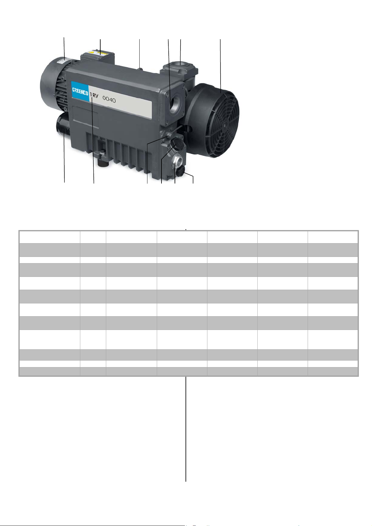
a. Motor data
b. Terminal box
c. Lifting ring
d. Gas discharge
e. Gas inlet
f. Radial fan
g. Oil filter
h. Nameplate
i. Ball valve
j. Oil fill plug
k. Oil sight glass
l. Oil drain plug
Pumping rate
(50HZ/60HZ)
Pressure limit
Motor power
(50HZ/60HZ)
Motor rotation speed
(50HZ/60HZ)
Noise
(50HZ/60HZ)
Max. saturated
vapor pressure
Removal rate of
vapor
Unit 1RV0020 1RV0025 1RV0040 1RV0063 1RV0100
m3/h 20/24 25/30 40/48 63/76 100/120
mbar 2.0 0.1 0.1 0.1 0.1
kW 0.75 0.75/1.1 1.1/1.5 1.5/2.2 2.2/3.0
min-1 3000/3600 1500/1800 1500/1800 1500/1800 1500/1800
dB 67/70 62/64 64/67 64/66 65/68
mbar 40 40 40 40 40
l/h 0.9 0.9 1.1 1.8 2.8
Operating
temperature
℃ 80/85 80/85 82/90 84/92 84/93
(50HZ/60HZ)
Ambient temperature
Oil quantity
Weight
See Oil for vacuum
℃
pump
L 0.45 1.0 1.0 2.0 2.0
kg 20 34 38 55 73
See Oil for vacuum
pump
Product description
Use
The vacuum pump is intended for:the suction of air and other dry,
non-aggressive, non-toxic and non-explosive gases.
Conveying media with a higher density than air leads to an increased
thermal and mechanical load on the vacuum pump and is permissible only
after prior consultation with Greenco.
Theallowabletemperaturerangeoftheinletgascanbereferredto
“Oil, Ambient temperature range”
in
See Oil for vacuum
pump
vapour within the gas flow can be tolerated within certain limits (see
“Installation and Commissioning, Operating Notes, Conveying
Condensable Vapours”). The conveyance of other vapours shall be agreed
upon with GREENCO.
The vacuum pump is intended for the placement in a non-potentially
explosive environment.
The vacuum pump is equipped with float valve (200) and return oil pipe.
The vacuum pump is thermally suitable for continuous operation (100%
output).
The vacuum pump is provided with oil return valve (280).
See Oil for vacuum
pump
See Oil for vacuum
pump

The vacuum pump is applicable to continuous operation (Pay attentions to
precautions of oil circulation; see Oil Circulation in Page 3; see Oil return in
Page 8).
The vacuum pump is ultimate pressure proof.
Principle of operation
The vacuum pump works on the rotating vane principle.
A circular rotor (14) is positioned centrically on the shaft of the vacuum
pump. The shaft of the vacuum pump is driven by the drive motor shaft by
means of a flexible coupling (310).
The rotor (14) rotates in an also circular, fixed cylinder (1), the centerline of
which is offset from the centreline of the rotor such that the rotor and the
inner wall of the cylinder almost touch along a line. Vanes (22), sliding in
slots in the rotor, separate the space between the rotor and the cylinder into
chambers. At any time gas is sucked in and at almost any time ejected.
Therefore the vacuum pump works almost pulsation free.
In order to avoid the suction of solids, the vacuum pump is equipped with a
mesh screen (261) in the suction connection.
In order to avoid reverse rotation after switching off, the vacuum pump is
equipped with a non-return valve (257)
NOTE: This valve shall not be used as a non-return valve or shut –off valve
to the vacuum system and is no reliable means to prevent suction of oil into
the vacuum system while the vacuum pump is shut down.
In case the vacuum pump is equipped a gas ballast (optional):
Through the gas ballast valve (440) a small amount of air is sucked into the
pump chamber and compressed together with the process gas. This
counteracts the accumulation of condensates from the process gas inside
the vacuum pump (see “Conveying Condensable Steams” in Page 8).
The gas ballast is designed with paper filter (Note: 1RV0020-1RV0040 gas
ballasts are configured with sintered metal filters).
Gas ballast version with ball valve:
The gas ballast line can be closed partially or completely by means of a ball
valve.
In order to improve the operating characteristics the outlet of the pump
chamber is equipped with a discharge valve (159).
Oil Circulation
The vacuum pump requires oil to seal the gaps, to lubricate the vanes (22)
and to carry away compression heat.
The oil reservoir is located on the pressure side of the vacuum pump (i.e.
high pressure) at the bottom of the bottom chamber of the oil separator (75).
The feed openings are located on the suction side of the vacuum pump (low
pressure).
Forced by the pressure difference between pressure side and suction side
oil is being drawn from the oil separator (75) through the oil supply lines
(210) and injected on the suction side.
Together with the sucked gas the injected oil gets conveyed through the
vacuum pump and ejected into the oil mist separator (75). Oil that separates
before the exhaust filter (120) accumulates at the bottom of the bottom
chamber of the oil separator (75).
Oil that is separated by the exhaust filter (120) accumulates at the bottom of
the upper chamber of the oil separator (75).
The flow resistance of the exhaust filters (120) causes the inside of the
exhaust filters (which is connected to be bottom chamber of the oil separator)
to be on a higher pressure level than the outside of the exhaust filters (the
upper chamber of the oil separator). Because of the higher pressure in the
bottom chamber it is not possible to let oil that drips off the exhaust filters
simply flow down to the bottom chamber.
As the vacuum pump is equipped with float valve (200) and oil return pipe at
the inlet:
The oil accumulated in the upper chamber of the oil separator flows in the
air inlet (250) through the float valve (200) and oil return pipe (195)
As the vacuum pump is equipped with oil return valve (280):
In continuous operating conditions, it is possible that the oil sucked into
pump chamber accumulates at the bottom of the upper chamber of the oil
separator, and then drains out along with the gas discharge/pressure,
resulting in oil-free pump operation; therefore, turn off the vacuum pump
and wait for at least 15 minutes for every 10 hours’ continuous operation.
Depending on different working environments, the period of continuous
operation may be even shortened (See Operation Notes in Page 8). After
the vacuum pump is turned off, the pressure difference in and out of exhaust
filter (120) is zero. The pressure in both chambers of oil separator is
balanced. Open the oil return valve (280) between two chambers to drain
the oil accumulated in the upper chamber of the oil separator by gravity into
the bottom chamber.
Cooling
The vacuum pump is cooled by:
-the ambient air around the vacuum pump, including oil mist separator (75)
-he air flow from the fan wheel (400)
-the conveyed gas
-he air flow from the fan wheels (321) on the shaft of the vacuum pump
On/Off switch
The vacuum pump comes without on/off switch. The control of the vacuum
pump is to be provided in the course of installation.
Safety
Intended use
DEFINITION: For the purpose of these instructions, “handling” the vacuum
pump means the transport, storage, installation, commissioning, influence
3

on operating conditions, maintenance, troubleshooting and overhaul of the
vacuum pump.
The vacuum pump is intended for industrial use. It shall be handled only by
qualified personnel.
The allowed media and operational limits according to the “Product
Description” (page 2) and the “Installation Prerequisites” (page 5) of
the vacuum pump shall be observed both by the manufacturer and the
operator.
The maintenance instructions shall be observed.
Prior to handling the vacuum pump these operating instructions sha ll
be read and understood. If anything remains to be clarified please
contact Greenco company!
Safety notes
The vacuum pump has been designed and manufactured with the
state-of-the-art technology and latest safety standards. Nevertheless,
residual risks may remain in case of improper installation or use. These
operating instructions inform about potential hazards where appropriate.
Safety notes are tagged with one of the keywords DANGER, WARNING and
CAUTION as follows:
DANGER!
Disregard of this safety note will always lead to accidents with
fatal or serious injuries.
WARNING!
Disregard of this safety note may lead to accidents with fatal or
serious injuries.
CAUTION!
Disregard of this safety note may lead to accidents with minor
injuries or property damage.
Emission of Oil Mist
CAUTION!
The non-OEM spares market offers exhaust filters that are
geometrically compatible with GREENCO vacuum pumps, but do
not feature the high retention capacity of genuine GREENCO
exhaust filters.
CAUTION!
Residual oil is present in gas discharged from vacuum pump.
Aspiration of gas conveyed by the vacuum pump over e xtended
periods can be harmful.
The room into which the gas conveyed by the vacuum pump is
discharged must be sufficiently vented.
Note:The possibly sensible smell is not caused by droplets of oil, though,
but either by gaseous process components or by readily volatile and thus
gaseous components of the oil (particularly additives).
Noise
The sound pressure level in free field is tested according to EN ISO 2151.
Transport
Caution:Empty vaccum pump can contain oil left from testing, so make sure
to keep vertical while transport and storage. Do not tilt or invert the vacuum
pump.
Transport in Packaging
Packed on a pallet the vacuum pump is to be transported with a forklift.
Transport without Packaging
In case the vacuum pump is packed in the carton package lined with internal
expanding lining:
Remove the lining out of the carton.
If the vacuum pump is lined with corrugated foil in the carton:
◆
Remove the corrugated foil from the carton.
If the vacuum pump is wrapped in foam plastic in the carton:
Remove the foam plastic from the carton.
If the vacuum pump is secured on the base with bolts:
Unscrew the bolts between the pump and bolts.
If the vacuum pump is secured on the base with retaining tape:
Remove the retaining tape.
Increased risk of damage to health .
In order to keep the emission on the lowest possible level only
genuine Greenco exhaust filters shall be used.
The oil in the process gas is separated to the greatest possible extent, but
not perfectly.
CAUTION
Do not walk, work or stand under suspended loads.
● Make sure the eyebolt (391) is intact (replace the damaged ones).
● Make sure the eyebolt (391) is reliably locked.
● Attach lifting gear securely to the eyebolt (391) on the cylinder.
● Attach lifting gear to a crane hook with safety latch .
● Lift the vacuum pump with a crane hook.
In case the vacuum pump was bolted to a pallet:
◆
Remove the stud bolts from the rubber feet.
CAUTION
Tilting a vacuum pump that is already filled with oil can caus e larg e
quantities of oil to ingress into the cylinder.
Starting the vacuum pump with excessive quantities of oil in the
cylinder will immediately break the vanes and ruin the vacuum
pump.
Once the vacuum pump is filled with oil it shall not be lifted
anymore.
Prior to every transport make sure that the oil is drained.
Storage
Short-term Storage
Version with gas ballast device with ball-cock:
Make sure that the ball-cock of the gas ballast (440) device is closed
Storage of vacuum pump equipped with ball-cock of the gas ballast
(440) and paper filter (applicable to 1RV0063 and 1RV0100):
Seal the paper filter of gas ballast (440) with tapes:
Storage of vacuum pump equipped with ball-cock of the gas ballast
(440) and sintered metal filter (applicable to 1RV0020 and 1RV0040):
Seal the sintered metal filter of gas ballast (440) with tapes:
Make sure that the suction connection/gas inlet and the gas
discharge/ pressure connection are closed
Store the vacuum pump
— if possible in original packaging,
— indoors,
— dry,
— dust free
— vibration free
Conservation
In case of adverse ambient conditions (e.g. aggressive atmosphere,
frequent temperature changes) conserve the vacuum pump immediately. In
case of favorable ambient conditions conserve the vacuum pump if a
storage of more than 3 months is scheduled.
During the factory tests, the vacuum pump inside has been completely in
contact with oil. In case of favorable ambient conditions, it is not necessary
to the pump with conservation oil. In case of unfavorable storage conditions,
the vacuum pump draining with conservation oil is advised. If anything
remains to be clarified please contact your Greenco representative!
Storage of vacuum pump with gas ballast (440) of ball-cock:
Make sure that the ball-cock of the gas ballast device (440) is closed
Storage of vacuum pump with gas ballast (440) of ball-cock and paper filter:
Seal the paper filter of gas ballast (440) with tapes;
Storage of vacuum pump with gas ballast (440) of ball-cock and sintered
metal filter;
Seal the sintered metal filter of gas ballast (440) with tapes;
Make sure all openings are sealed; seal all the openings not
protected with PTEF tape, washer or O-rings.
Fill in conservation oil in small quantities by the suction connection,
observe the oil type and the given quantity in the tables below:
Oil Type
Corex HLP-D 68, P/N 0831 512 575
(or a conservation oil from same quality)
NOTE: VCI stands for “Volatile Corrosion Inhibitor”. VCI-products (film,
paper, cardboard, foam) evaporate a substance that condenses in
molecular thickness on the packed good and by its electro-chemical
properties effectively suppresses corrosion on metallic surfaces. However,
VCI-products may attack the surfaces of plastics and elastomers. Seek
advice from your local packaging dealer! GREENCO uses CORTEC VCI
126 R film for the overseas packaging of large equipment.
Wrap the vacuum pump in VCI film.
Store the vacuum pump.
if possible in original packing
indoors
dry
dust free
vibration free
Commissioning after conservation
Make sure that the gasket, plug or adhesive tape are removed from the
ports.
Commission the vacuum pump as described in the chapter “Installation
and Commissioning” (Page 5).
Installation and Commissioning
Installation prerequisites
CAUTION
In case of non-compliance with the installation prerequisites,
particularly in case of insufficient cooling:
Risk of damage or destruction of the vacuum pump and adjoining
plant components!
Risk of injury!
The installation prerequisites must be complied with.
Make sure that the assembly of the vacuum pump is carried out in line
with the essential safety requirements.
Mounting Position and space
Make sure that the environment of the vacuum pump is not potentially
explosive.
Make sure that the following ambient conditions will be complied
with:
— Ambient temperature: see “Oil”
If the vacuum pump is installed in a environment of low temperature:
— Ambient pressure: atmospheric pressure
Fit the vacuum pump either with an oil sump heater (on request) or
fit the vacuum pump with a temperature switch and control the vacuum
pump in such a way that it will start automatically when the oil sump
5

temperature rise above the allowable temperature.
p
be maintained after switching off the vacuum pump:
Make sure that the environmental conditions comply with the
protection class of the drive motor (according to the nameplate).
Make sure that the base for placement/mounting base is even.
To warrant a sufficient cooling, make sure there is a clearance of
minimum 50cm between the pump and nearby wall.
Make sure that no temperature sensitive parts (plastics, wood,
cardboard, paper, electronics) will touch the surface of the vacuum
pump.
Make sure that the installation space or location is vented so that a
sufficient cooling of the vacuum pump is warranted.
CAUTION
During operation the surface of the vacuum pump may reach
temperatures of more than 70℃.
Risk of burns!
Make sure that the vacuum pump will not be touched inadvertently
during operation, provide a guard if appropriate
Make sure that the oil sight glass (83) will remain easily accessible if
the oil change is meant to be performed on location:
Make sure that the oil drain port (95), the oil filter (100) and the oil fill
port (88) will remain easily accessible.
Make sure that enough space will remain for the replacement of the
exhaust filter(s) (120).
Provide a manual or automatic operated valve ( =non-return valve)
in the suction line.
(the non-return valve that is installed inside the suction connection is not
meant to be used for this purpose!)
If the vacuum pump is planned to be used for the suction of gas that
contains limited quantities of condensable vapor:
Provide a shut-off valve, a drip-leg and a drain valve in the suction
line, so that condensates can be drained from the suction line.
Make sure that the suction line does not contain foreign objects, e.g.
welding scales.
Discharge connection
It is required that the gas should be discharged without any obstruction; do
not close or plug the discharge pipes or use the vacuum pump for
compressing air.
The following guidelines for the discharge line do not apply, if the aspirated
air is discharged to the environment right at the vacuum pump.
CAUTION
The discharged air contains small quantities of vacuum oil.
Staying in vacuum oil contaminated air bears a risk of damage to
health.
If air is discharged into rooms where persons stay, sufficient
ventilation must be provided for.
Make sure that the discharge line fits to the gas discharge connection
(155) of the vacuum pump.
In case of using a pipe:
Suction Connection
Make sure that the pipe will cause no stress on the discharge
CAUTION
Intruding foreign objects or liquids can destroy the vacuum
pump.
In case the inlet gas can contain dust or other foreign solid particles:
Make sure that a suitable filter (5 micron or less) is installed upstream
the vacuum pump.
Make sure that the suction pipeline fits to the suction connection/gas
inlet (260) of the vaccum pump.
Make sure that the gas will be sucked through a vacuum-tight flexible
hose or a pipe.
In case of using a pipe:
Make sure that the line size of the discharge line over the entire
In case of very long discharge pipelines it is prudent to use larger line sizes
in order to avoid a loss of efficiency and an overload of the vacuum pump.
Seek advice from your Greenco representative.
Keep the back pressure at the discharge port (155) below 1.3 bar (absolute
pressure) (Check it by starting the vacuum pump when appropriate).
Make sure that the discharge line either slopes away from the
connection, if necessary use bellows.
length is at least as large as the gas discharge connection (153) of
the vacuum pump.
vacuum pump or provide a liquid separator or a drip leg with a drain
cock, so that no liquids can back up into the vacuum pump.
Make sure that the pipe will cause no stress on the vacuum pump's
connection, if necessary use bellows.
In case of very long suction lines it is prudent to use pipes of large line
sizes in order to avoid a loss of efficiency. Seek advice from your
Geenco representative.
If two or more vacuum pumps work on the same suction line, if the volume
of the vacuum system is large enough to suck back oil or if the vacuum shall
WARNING
Discharge lines made from non-conducting material ca n build up
static charge.
Static discharge can cause explosion of potentially existing oil
mist.
The discharge line must be made of conducting material or
rovisions must be made against static discharge.
Electrical connection/Controls
Make sure that the stipulations acc. to the EMC-Directive
2004/108/EC, Standard 2006/95/EC for LV applications as well as the
EN-standards, electrical and occupational safety directives and the
local or national regulations, respectively, are complied with.
Make sure that the voltage and frequency of power supply is
compatible with the data on the nameplate of the drive motor (400).
Make sure that an overload protection according to EN 60204-1 is
provided for the drive motor.
Make sure that the drive of the vacuum pump will not be affected by
electric or electromagnetic disturbance from the mains; if necessary
seek advice from the GREENCO service.
In case of mobile installation:
Provide the electrical connection with grommets that serve as
strain-relief.
Installation
Mounting
Make sure that the “Installation Prerequisites” (Page 5) are complied
with.
Set down or mount the vacuum pump at its location
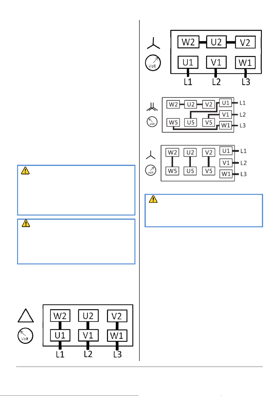
Star connection (High voltage):
Star connection, multi-voltage motor (High voltage):
Star connection, multi-voltage motor (High voltage):
Connecting electrically
WARNING
Risk of electrical shock, risk of damage to equipment .
Electrical installation work must only be executed by qualified
personnel that knows and observes the following regula tions:
- IEC 364 or CENELECH HD 384 or DIN VDE 0100, respectively,
- IEC-Report 664 or DIN VDE 0110,
-BGV A2 (VBG 4) or corresponding nationa l accident prevention
regulation .
CAUTION
The connection schemes given below are typical. Depending on
the specific order or for certain markets deviating connection
schemes may apply.
Risk of damage to the drive motor!
The inside of the terminal box shall be checked for drive motor
connection instructions/schemes.
Electrically connect the drive motor (400).
Connect the protective earth conductor
Diagrams of electrical connection:
Delta connection (Low voltage):
CAUTION
Operation in the wrong direction of rotation can destroy the
vacuum pump in short time.
Prior to starting-up it must be made sure that the vacuum pump is
operated in the proper direction.
Setting vacuum pump with three-phase motor
Determine the intended direction of rotation with the arrow (431).
“Bump” the drive motor (400).
Watch the fan wheel of the drive motor (400) and determine the
direction of rotation just before the fan wheel stops.
If the rotation of the fan wheel must be changed:
Switch any two of the drive motor wires in the terminal box.
Connecting Lines/Pipes
In case the suction line is equipped with a shut-off valve:
Connect the suction line.
Connect the discharge line.
Installation without discharge line:
Make sure that the gas discharge (155) is open.
Make sure that all provided covers, guards, hoods etc. are mounted.
Make sure that cooling air inlets and outlets are not covered or
7

obstructed and that the cooling air flow is not affected adversely in
any other way.
Filling Oil
In case the vacuum pump was treated with conservation oil:
Drain the remainders of conservation oil and top up oil.
CAUTION
The vacuum pump is shipped without oil.
Operation without oil will ruin the vacuum pump in short time.
Prior to commissioning it must be made positively sure that oil is
The vacuum pump is delivered without oil (oil specification see “Oil” in page
22).
● According to the description in Oil (Page 22), at least 2L oil shall be kept
in the oil tank (Note: 0.45L oil in 1RV0020, 1L in 1RV0025 and
1RV0040).
NOTE: The amount given in these operating instructions is a guide. The oil
sight glass (83) indicates the actual amount to be filled in.
CAUTION
Filling oil through the gas inlet (260) will result in breakage of the
vanes (22) and destruction of the vacuum pump.
Oil may be filled through the oil fill port only (88).
CAUTION
During operation the oil separator is filled with hot, pressurised
oil mist.
Risk of injury from hot oil mist with open oil fill port .
Risk of injury if a loosely inserted oil fill plug (88) is ejected .
Remove the oil fill plug (88) only if the vacuum pump is stopped.
The vacuum pump must only be operated with the oil fill plug (88)
firmly inserted.
Remove the oil fill plug (88)
Filling about 2L oil according to the values set in the table “Oil” (Note:
0.45L oil in 1RV0020, 1L in 1RV0025 and 1RV0040).
Make sure that the level is between the MIN and the MAX-markings
of the oil sight glass (83)
Make sure that the sealing ring (89) is inserted into the oil fill plug (88)
and undamaged, replace if necessary
Firmly reinsert the oil fill plug (88) together with the sealing ring (89)
NOTE: Starting the vacuum pump with cold oil is made easier when at this
very moment the suction line is neither closed nor covered with a rubber
mat.
Switch on the vacuum pump.
In case the suction line is equipped with a shut-off valve:
Close the shut-off valve
In case the suction line is not equipped with a shut-off valve:
Cover the suction connection with a rubber mat (260).
Let the vacuum pump run for a few minutes.
Shut down the vacuum pump and wait a few minutes.
Make sure that the level is between the MIN and the MAX-markings
of the oil sight glass (83)
In case the level has fallen below the MIN-marking of the oil sight
glass:
Top-up oil
In case the suction line is equipped with a shut-off valve:
Open the shut-off valve
In case the suction line is not equipped with a shut-off valve:
Remove the rubber mat, and connect the suction connection
Recording of Operational Parameters
As soon as the vacuum pump is operated under normal operating
conditions:
Measure the drive motor current and record it as reference for future
maintenance and troubleshooting work.
Version with exh au st filter pressure gauge:
Read the scale of the exhaust filter pressure gauge and record it as
reference for future maintenance and troubleshooting work (Check
during operation in Page 11).
Operation Notes
Application
CAUTION
The vacuum pump is designed for operation under the conditions
described below.
In case of disregard risk of damage or destruction of the vacuum
pump!
Risk of Injury!
The vacuum pump must be operated under the conditions
described below.
The vacuum pump is designed for the suction of air and other dry,
non-aggressive, non-toxic and non-explosive gases
Conveying media with a higher density than air leads to an increased
thermal and mechanical load on the vacuum pump and is permissible only
after prior consultation with Greenco company.
Max. allowed temperature of the inlet gas, see “Oil, Ambient temperature
range”
In case the vacuum pump is equipped with a gas ballast (optional) water
vapor within the gas flow can be tolerated within certain limits (see
“Installation and Commissioning, Operating Notes, Conveying Condensable
vapors” in Page 8). The conveyance of other vapors shall be agreed upon
with GREENCO.
The vacuum pump is made for the intended use in potentially non-explosive
areas.
If the vacuum pump is equipped with ball-lock valve (200) and oil return
pipe:
 Loading...