


INSTALLATION/OPERATING
INSTRUCTIONS FOR
TIME DELAY SWITCH - TLS
Thank you for purchasing a quality time delay switch from Greenbrook. Please read
these instructions fully prior to initial use.
Every effort has been made to ensure that the guidance information on this sheet will
enable the installation of the switch to be carried out safely and correctly.
IF IN DOUBT, INSTALLATION SHOULD BE
MADE BY A QUALIFIED ELECTRICIAN
IN ACCORDANCE WITH CURRENT
WIRING REGULATIONS.
The TLS is suitable for controlling incandescent (GLS), fluorescent and compact
fluorescent lighting. The timer can be used on its own, or with other units in a 2-wire
(no neutral) lighting circuit, and can therefore be installed on new installations or
replace existing single gang switches.
IIMMPPOORRTTAANNTT
All metal boxes must be earthed.
Please ensure that the top and bottom lugs are removed, if fitted, from metal wall boxes
before fitting as there is a danger of the common terminal (Marked Com) fouling a
mounting lug and causing an earth fault if boxes having four lugs are used.
IINNSSTTAALLLLAATTIIOONN
The TLS has been designed for mounting on a 20mm or 25mm deep standard BS single
gang accessory box. However, it is recommended that deeper boxes are used where
extra space is required for additional cables, for example when looping in. Please ensure
that there is adequate space for wiring.
It is recommended that if using moulded backing boxes, please ensure that the back box
only has two mounting lugs as certain manufacturers do not allow adequate clearance
for the Time Delay Switch terminal connections. Some moulded boxes also have two
locating pips on the mounting face which can obstruct the Time Delay Switch and
prevent it from fitting flush. These will need to be ground off.
If mounting on surfaces such as unplastered brickwork or the mounting box is
completely true to the wall surface, please avoid over tightening the mounting screws,
as this may cause the switch faceplate to distort and in turn lock the plunger in the
“ON”position.
OOPPEERRAATTIIOONN
The switch is operated by pressing the plunger button. This will “make” or “break” the
change-over contacts. The plunger will gradually return to its original position during the
time delay sequence, eventually returning the change-over contacts to their original
position using the snap action of the switch. The face-plate is moulded in a semitranslucent material and therefore it is normal to occasionally see a flash when the
contacts “make” or “break”.
WWIIRRIINNGG DDIIAAGGRRAAMMSS
COM (Common) and NC (Normally closed) Contacts are connected when the timer is
off.COM and NO (Normally open) Contacts are connected when the plunger button is
pressed, and will stay connected for the period of the time delay. As these units are designed for lighting circuits, a neutral feed is not required at the switch position.
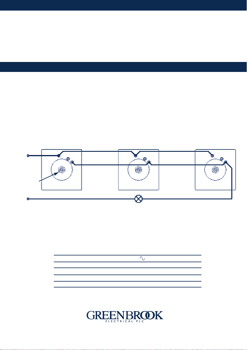
To use the Time Delay Switch as a normal lightswitch type operation, connect the “Live
Feed” Wire into the COM Terminal, and the “Switched Live” wire into the NO terminal.
Additional switches can be wired in parallel to control the same load.
(please see diagram below)
Live
Feed
OM
C
C
N
O
N
Switched Live
COM
N
Live Feed
Live Feed
C
O
N
Switched Live
COM
C
N
Timing Screw
Neutral
Switched Live
Lights
Timer Adjustment
The timing can be adjusted between 10 seconds and 10 minutes (approx.) by turning
the Brass Timing Screw in the centre of the plate on the back of the unit. Turning the
Timing screw clockwise will increase the time delay.
TECHNICAL DATA
Switch Current Rating: 240V, AC 50Hz
Incandescent (GLS) Load: 6A
Fluorescent Load: 3A
Compact Fluorescent Load: 6 Fittings max. (3A Peak)
Adjustable Time Delay: 10 Seconds to 10 Minutes (Approx)
PPLLEEAASSEE KKEEEEPP TTHHEESSEE IINNSSTTRRUUCCTTIIOONNSS SSAAFFEE FFOORR FFUUTTUURREE RREEFFEERREENNCCEE
O
N
Issue no: 701663
WEST ROAD . HARLOW
ESSEX . CM20 2BG . UK
s a l e s @ g r e e n b r o o k . c o . u k
W W W . G R E E N B R O O K . C O . U K
 Loading...