

Page 1
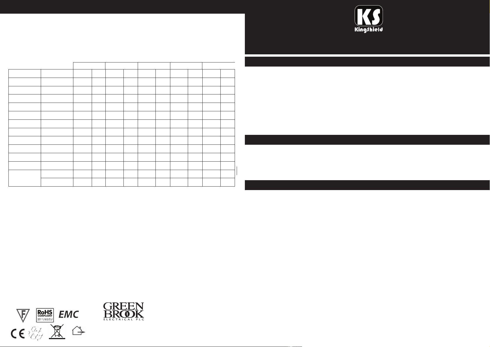
EMERGENCY LUMINAIRE TEST RECORD SHEET
LUMINAIRE TYPE/REF:_________________________________
DATE OF INSTALLATION:_______________________________
LOCATION:________________________
2nd Year
ate
D
Signed
Date
3rd Year
Signed
Month
1
2
3
4
5
6
7
8
9
10
11
12
Test
UNCTIONAL
F
UNCTIONAL
F
UNCTIONAL
F
FUNCTIONAL
FUNCTIONAL
FUNCTIONAL
FUNCTIONAL
FUNCTIONAL
FUNCTIONAL
FUNCTIONAL
FUNCTIONAL
THREE HOUR
FUNCTIONAL
1st Year
Signed
Installation / Operating
Instructions for ELTSLED20NM
4th Year
Signed
ate
D
5th Year
igned
S
ateDate
D
This unit should be fitted by a qualified electrician in accordance with the appropriate
national/IEE wiring regulations. Switch off mains supply before installation and maintenance.
This product must not be modified. Any modification will negate any Safety Mark Approvals and
may render the product unsafe. GreenBrook accepts no responsibility for modified products.
This product must be installed in accordance with these instructions. This fitting should not be
installed in close proximity to any external source of heat or covered with any heat insulating
material, air flow around the fitting should not be restricted. Note any minimum distances to
adjacent surfaces. This unit should be connected to the lighting supply circuit, or fused at a
maximum of 5A.
SAFETY
GENERAL DESCRIPTION
This unit is a non-maintained (NM suffix), self-contained emergency luminaire.
To confirm model type, check the data provided on the fitting and packaging.
ELTSLED20NM Non-maintained: Incorporates two 40 LED lamps which are
illuminated only under mains failure.
INSTALLATION INSTRUCTIONS
Follow these instructions carefully to ensure safe and reliable operation. Retain this leaflet for
future reference. The emergency luminaire should be connected to a stable and permanent
mains supply of the correct rated voltage and frequency as stated on the product specification
label. This may be from the lighting supply circuit, or fused at a maximum of 5A. To facilitate
testing a fused spur box can be included in the unswitched permanent live supply.
Class I. This product must be earthed.
PLEASE KEEP THESE INSTRUCTIONS SAFE FOR FUTURE REFERENCE
WEST ROAD . HARLOW
ESSEX . CM20 2BG . UK
sa les@ gr ee nbr ook. co .u k
W W W. G R EE N B R O OK . C O . UK
All switching etc, shall comply with BS 5266 Part 1. Unless specifically permitted, emergency
luminaires should not be connected or controlled by any energy management device.
Before commencing installation, ensure that the electricity supply is disconnected. Surge
suppressors may be required at the point of connection to the supply wiring when installing
luminaires to MICC cable.
1. Unclip the front cover using the screwdriver clips as shown on product.
2. Select and remove a knock out corresponding with the conduit and / or cable run and secure
Issue no: 703695
a suitable bush within the hole to prevent damage to the incoming cable.
3. Mount the case in position on a suitable surface ensuring an adequate airflow will be
maintained around it, or secure to wall using the three hole dimensions on the back case.
Page 2
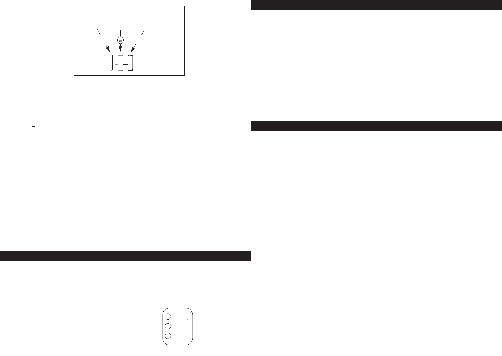
NON-MAINTAINED
NEUTRAL
(BLUE)
EARTH
GREEN/YELLOW
N
PERMANENT LIVE
L
E
(BROWN)
4. Bring the cable into position and make the correct electrical connections as follows:
Note: The ELTSLED20NM uses screwless terminals.
Class I. This product must be earthed.
Terminal (L): This is the live supply to the charging circuit and must be permanent
and unswitched.
Terminal ( E): This is for the earth and must be connected.
Terminal (N): This is the neutral supply and must be permanent.
Colour code: Brown=Live Blue=Neutral Green/Yellow=Earth
Conductor Space Size 1.0mm2 - 2.5mm2Solid or Stranded.
Ensure that no strands of bare wire have escaped the terminals.
5. Mark the battery cell pack with the date of installation and connect the battery.
6. Refit the front cover, taking care to ensure that no wires are trapped.
7. To adjust the position of the lamp heads, loosen the axis screws before positioning so as not
to cause excess strain on the lamp fixings.
WARNING
The battery cell pack must be CONNECTED before the mains is switched on.
Failure to comply with these installation instructions may result in irreparable damage to the
main circuit.
DO NOT HIGH-VOLTAGE INSULATION TEST THIS UNIT, OR THE LIGHTING SYSTEM WITH
THIS UNIT CONNECTED.
COMMISSIONING & TESTING
Switch on the mains supply, check that ‘Charge ON’, ‘Lamp 1’ and ‘Lamp 2’ green LED
indicators are lit.
Allow a brief time for initial partial charging and then isolate the permanent live supply by
removing the fuse from the fused spur box. Check to ensure the lamps are illuminated from the
battery cell pack supply. After a further 24 hours on a continuous charge, and only at a safe and
appropriate time, mains failure should be simulated to ensure that full duration rating is
achieved. Thereafter the recharge time is 24 hours.
Function of LED Indicators
1. Charging
2. Lamp 1 ok
3. Lamp 2 ok
1.
2.
3.
Charge
Lamp 1 ok
Lamp 2 ok
MAINTENANCE
Servicing should only be carried out after the luminaire has been made electrically safe.
Lamps should be replaced at set intervals for maximum system integrity, use only lamps of the
correct type and rating and follow the lamp manufacturers instructions.
Cleaning should be carried out at regular intervals to ensure that dirt does not accumulate to an
extent that will impair the electrical and / or thermal safety of the luminaire. Regular cleaning will
also ensure that the optical performance is maintained.
Battery packs should be replaced when the luminaire fails to meet its rated duration, regardless all
batteries must be replaced after 4 years service.
The disposal of components from the luminaire may require consultation with local authorities.
The disposal of batteries is subject to Local Authority Regulations, and the By-Laws Department
for disposal of toxic waste should be consulted for specific guidance. Battery cell packs must not
be incinerated. Do not dispose with household waste, subject to conditions in the WEEE directive.
SPECIFICATION
Input Voltage: 220/240V AC, 50/60Hz
LED Power Consumption: 3.2W Total, 130 lm/W
Fuse installed: 1.0A, 250VAC
Battery Installed or replacement: 3.6V, 4.5Ah Ni Cad
LED Built-in: LED 40 + 40 pcs
IP Rating: IP20
Operating Environmental Temperature: -10°C + 40°C
Re-charging Time: 24 hours
Emergency Duration: More than 3 hours
Routine Inspection & Test Procedure
All tests should be undertaken during daylight hours at times of minimum risk and be in accordance with
the recommendations of BS 5266 Part 1: 2005.
DAILY - Check that the three green LED battery charging / lamp failure indicators are illuminated.
MONTHLY - In addition to the daily check, a functional test through simulation of mains supply failure
should be carried out to confirm lamps are illuminated from the battery cell pack supply. This test need only
be approximately 30 seconds. It should not exceed one quarter of the rated luminaire duration.
SIX - MONTHLY - In addition to the monthly test, the lamps should be illuminated from the battery cell
pack supply for a continuous period of at least one hour.
THREE - YEARS - In addition to the monthly tests the lamps should be illuminated from the battery cell
pack supply for the full rated duration of the luminaire. (180 minutes).
ANNUALLY THEREAFTER - As above, i.e, Check that the luminaire operates for the full rated duration (180
minutes).
At the end of each test period the mains supply should be restored and a check made to ensure that all
three green LED battery charging/lamp failure indicators are illuminated.
 Loading...