

Page 1
SSAAFFEETTYY
1. Minimum distances around the apparatus for sufficient ventilation.
2. The ventilation should not be impeded by any obstructions.
3. Not to be exposed to any dripping or splashing.
4. Batteries are the Ni-MH type and have a normal service life approximately 4 years. Batteries
should only be replaced with the type specified, and replaced by a qualified person.
5. Before commencing installation ensure that the electricity supply and battery pack are
disconnected.
Instruction Manual
LED Emergency Exit Sign
Model: ELEXLED
This unit should be installed by a competent person and in accordance the current IEE Wiring
Regulations. If in doubt consult a qualified electrician
maintenance or replacing lamps.
This unit is a maintained/non-maintained self-contained emergency fitting.
. Switch off mains supply before installation,
EEMMEERRGGEENNCCYY LLUUMMIINNAAIIRREE TTEESSTT RREECCOORRDD SSHHEEEETT
FITTING TYPE/REF:_________________________________
DATE OF INSTALLATION:_______________________________
LOCATION:________________________
Month
1
2
3
4
5
6
7
8
9
10
11
12
Test
FUNCTION
FUNCTION
FUNCTION
FUNCTION
FUNCTION
FUNCTION
FUNCTION
FUNCTION
FUNCTION
FUNCTION
FUNCTION
FUNCTION
1st Year
Signed
Date
2nd Year
Signed
PPLLEEAASSEE KKEEEEPP TTHHEESSEE IINNSSTTRRUUCCTTIIOONNSS SSAAFFEE FFOORR FFUUTTUURREE RREEFFEERREENNCCEE
WEST ROAD . HARLOW
ESSEX . CM2 0 2BG . UK
WW W.G REE NB ROOK .C O.U K
Date
3rd Year
Signed
Date
Signed
4th Year
Date
5th Year
Signed
Date
ELEXLED - Maintained or Non-Maintained.
Incorporates 20 + 6 x leds which are illuminated either via a separate switched supply or under
mains failure conditions.
1.
2.
3.
4.
5.
6.
7.
8.
9.
10.
11.
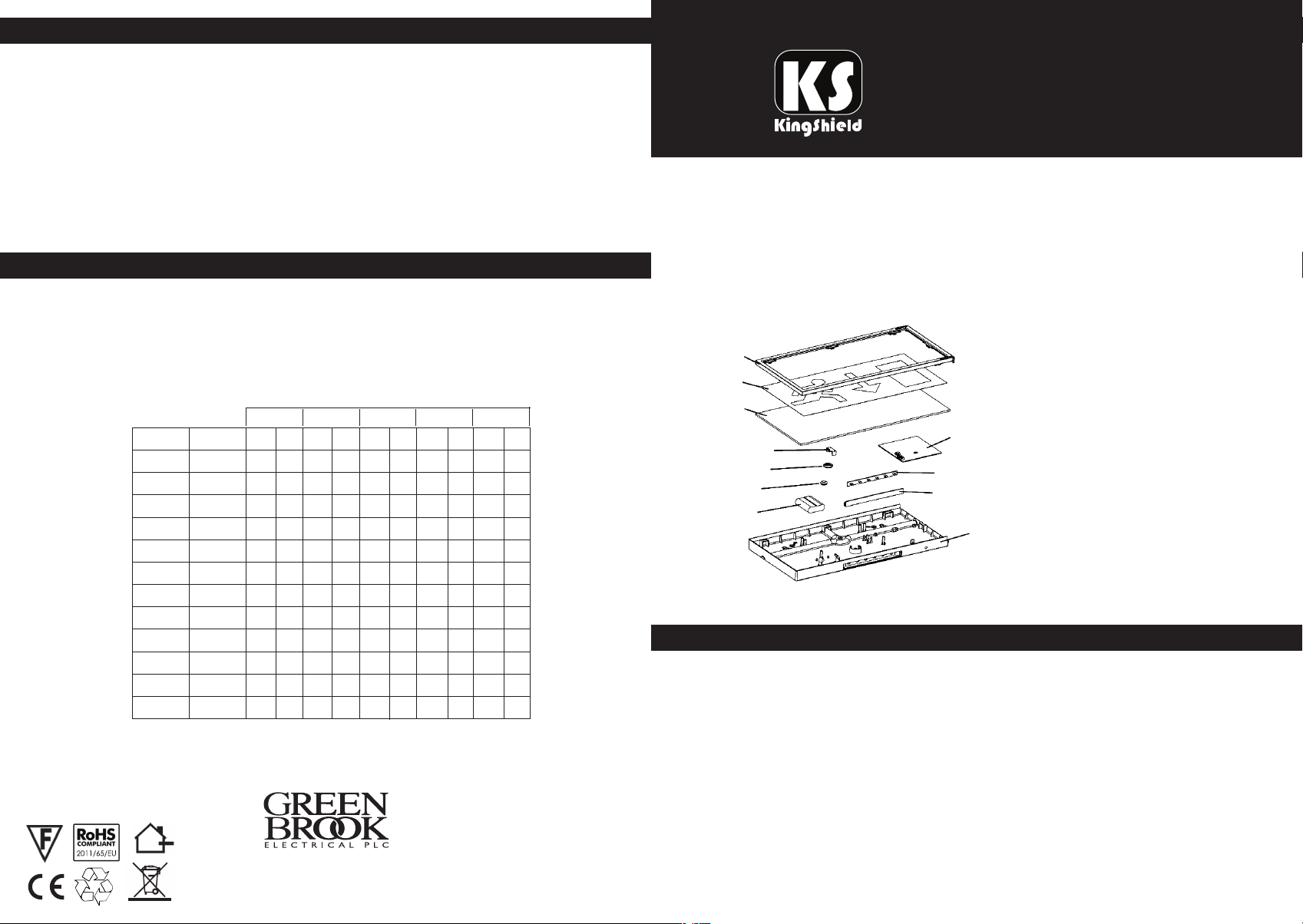
ELEXLED Parts:
1. Cover
2. Legend
3. Light guide plate
4. Holder 1 of power line
5. Holder 2 of power line
6. Rubber ring
7. Battery
8. Main PCB
9. LED PCB
10. Translucent panel
11. Bottom casing
SSPPEECCIIFFIICCAATTIIOONN
Input Voltage: 220/240V AC, 50/60Hz, 5W
LED Power: 1.3W
Surface Brightness: >200cd/m
Fuse installed or replacement: 1A, 250VAC
Battery Installed or replacement: Ni-MH 3.6V, 2000mAh
LED Built-in: LED 20 + 6 pcs
IP Rating: IP20
Issue no: 703114
Operating Environmental Temperature: 0°C - 40°C
Re-charging Time: 24 hours
Emergency Duration: More than 3 hours
2
Page 2
EEXXIITT SSIIGGNN AASSSSEEMMBBLLEE
3. Allow a short period for part charging of the batteries, and then isolate the mains supply to
the fitting in order to check the correct operation of the fitting in emergency mode. When
first installed, after a continuous charge for 36 hours, a mains failure should be simulated to
ensure that the fitting works for its specified time greater than 3 hours(only at a safe &
appropriate time). After this the fitting will be fully charged with in 24 hours, after
re-application of mains.
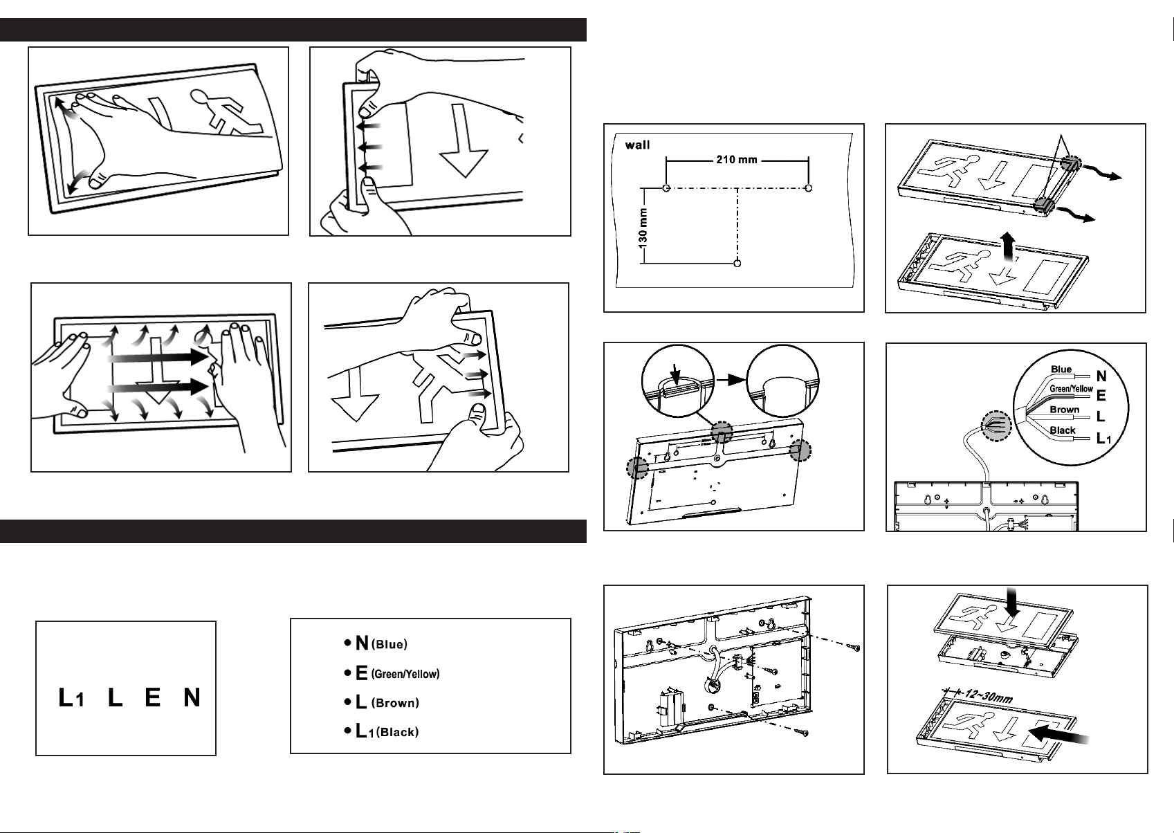
Press here, right push
Dia 1.
1. Press the corner on the left of the
panel into the slot. (Dia 1.)
Dia 3.
3. Press the up and down sides into
the slot. (Dia 3.)
2. Push the exit sign to the end of
left. (Dia 2.)
4. Right move the panel to be in the
middle. (Dia 4.)
Dia 2.
Dia 4.
IINNSSTTAALLLLAATTIIOONN
1. Connect mains supply as follows:
- Connect Brown wire only to Live for Non-Maintained operation.
- Connect Brown and Black to Live for Maintained operation.
- Connect Brown wire to Live and insert switch between Black wire and Live for switched operation.
Dia 1.
1. Fixing holes dimensions. (Dia 1.)
Take out
Dia 3.
3. Take out the semi-circle blank on
the mains entry. (Dia 3.)
Dia 2.
2. Open the cover. (Dia 2.)
Power supply
Dia 4.
4. Wiring diagram. (Dia 4.)
(Non-Maintained)
(Switch-wire)
2. When all connections have been made reassemble the fitting completely.
3. Switch on 220-240V AC supply and check that the green LED indicator illuminates to
confirm charging of batteries.
5. Fix the base on the wall with
screws. (Dia 5.)
Dia 5.
Dia 6.
6. Assemble the cover. (Dia 6.)
 Loading...