

Page 1

HDMI Expander-Cat5
Digital
Media Product
User Manual
HDMI-E102T
HDMI-E102TR
HDMI-E104C
HDMI-E108C
Page 2
User Manual
2
3
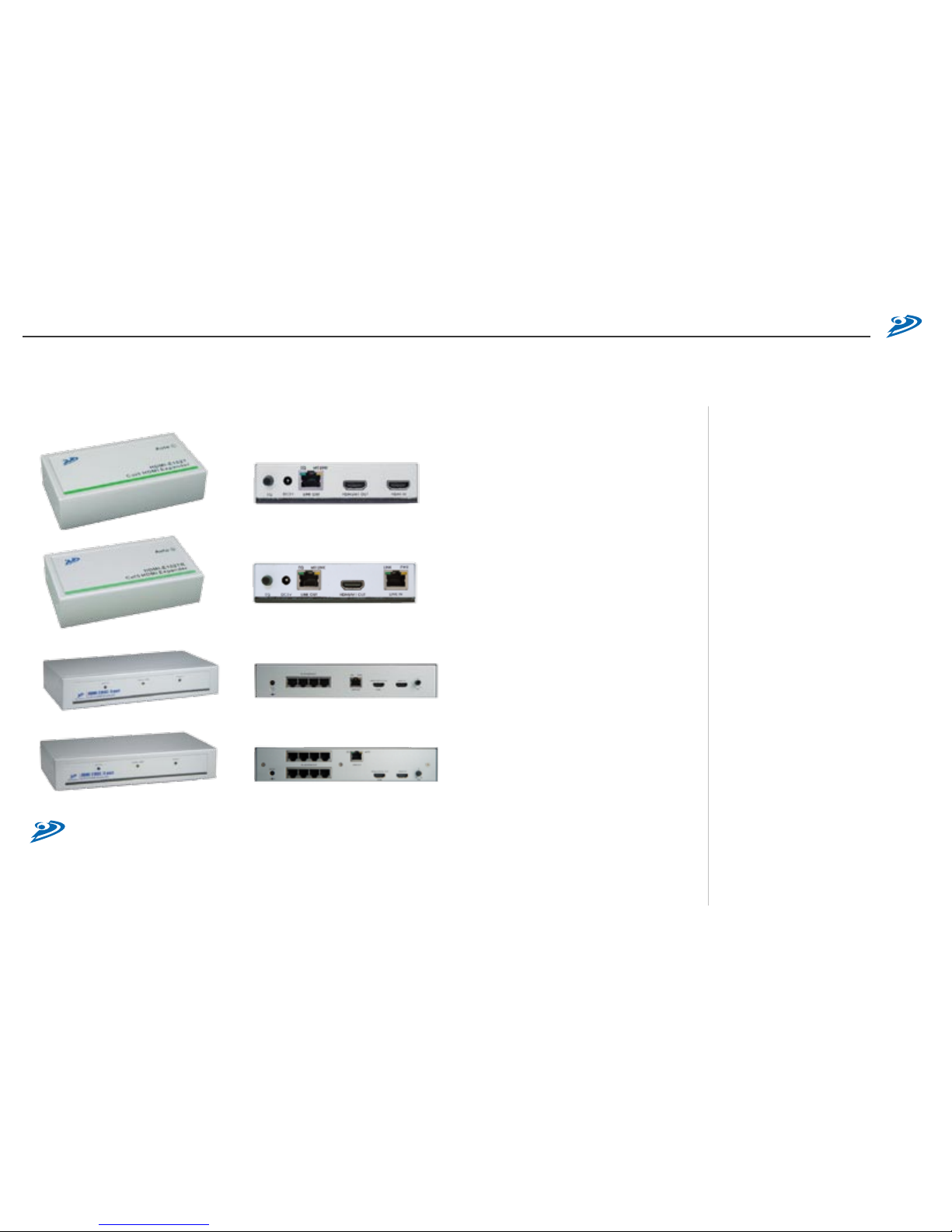
One-Port HDMI Transmitter : HDMI-E102T
One-Port HDMI Transceiver : HDMI-E102TR
4-Port HDMI Transceiver with One Local Input
8-Port HDMI Transceiver with One Local Input
TABLE OF CONTENTS
Package Contents
Introduction
Key Features
Panel Description
Installation and Operation
Specication
4
5
7
8
10
19
(C) 2007 Green -Bo x Tech nolog y C o., Ltd.,
All Ri ght s Rese rved
Res erves in th e h ard ware, packa gin g a nd
acc ompany ing d ocu men tation .
Page 3
User Manual
4
5
/
Introduction
The Cat5 HDMI Expander system consists of Transmitter, Transceiver and
Receiver. The system can extend HDMI signals over Cat5/5e/6 FTP cable.
By cascading Transceivers, it is possible to extend the HDMI signals with
almost unlimited capacity. The Cat5 HDMI Expander system is a great
solution for digital signage, public information display, and large scale
demonstration, where crystal-clear, high-resolution digital video needs to be
shown.
By taking the advantage of cost efficient Cat5/5e/6 FTP cable, the Cat5
HDMI Expander can simplify installation. With its unlimited cascading
capacity, you can extend digital video displays almost anywhere. The
Transmitter and Transceiver units are tted with magnetic pads, enabling
them to be quickly attached to metal surfaces. A screw xing plate is also
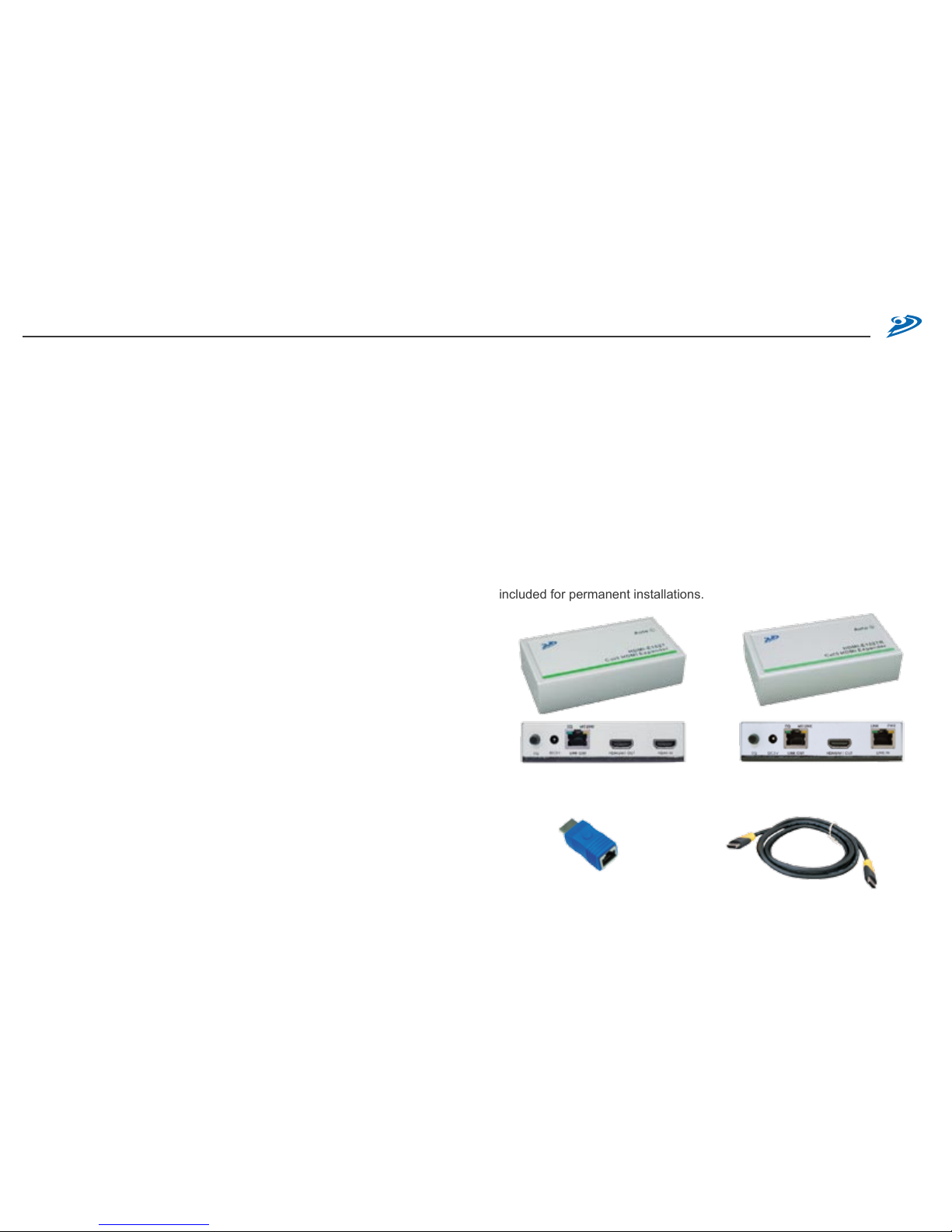
included for permanent installations.
/
Package Contents
A. HDMI-E102T : One Port HDMI Expander Transmitter
1. HDMI-E102T x 1
2. HDMI Cable x 1
3. Power Adaptor DC5V x 1
4. User Manual
B. HDMI-E102TR : One Port HDMI Expander Transceiver
1. HDMI-E102TR x 1
2. Power Adaptor DC5V x 1
3. User Manual
C. HDMI-E104C: 4-Port HDMI Transceiver
1. HDMI-E104C x 1
2. HDMI Cable x 1
3. HDMI-HR Receiver x 1
4. Power Adaptor DC5V, 3A x 1
D. HDMI-E108C: 8-Port HDMI Transceiver
1. HDMI-E108C x 1
2. HDMI Cable x 1
3. HDMI-HR Receiver x1
4. Power Adaptor DC5V, 3A x 1
HDM I- E10 2T R
One -P ort H DMI Tr ansce iver
HDM I Cab le (for Play er )
HDM I- HR
HDM I- RJ4 5 Recei ver
Page 4
User Manual
6
7
/
Key Features
1. Unlimited cascading of HDMI over Cat5/5e/6 FTP cable
2. The sys tem con s ist s of Tran s mit ter, Tr ansc eive r an d R e cei v er.
Transmitter has a HDMI local connection and extends the HDMI signal
over Cat5/5e/6 FTP cable.
3. Transceiver has a HDMI input port (RJ-45 or HDMI type), 4/8 HDMI
RJ-45 output ports and cascading function to extend the HDMI signal
over Cat5/5e/6 FTP cable.
4. Video Amplier Bandwidth: 1.65GHz
5. Maximum distance between Transmitter and Transceiver is determined
by display resolution and FTP cable type and quality. Typical distances
are: < 80m. for 480p, < 70m. for 720 p/108 0i, < 30m. for 1080p .
(Distances are based on FTP cable skew < 15ns/100m).
6. Maxim um dist ance betwe en Tra nscei ver a nd HDMI -HR R eceiv er
determined by d is pl ay resolution and FTP cable type and quality.
Typical distances are: < 30m. for 480p/720p/1080i, < 15m. for 1080p.
(Distances are based on FTP cable skew < 15ns/100m).
7. HDMI Input/Output Connector: HDMI digital signal
8. EQ control to adjust the video quality
9. LED status to indicate HDMI activity
10.Magnetic pad and attachable metal plate on each device for easy
installation
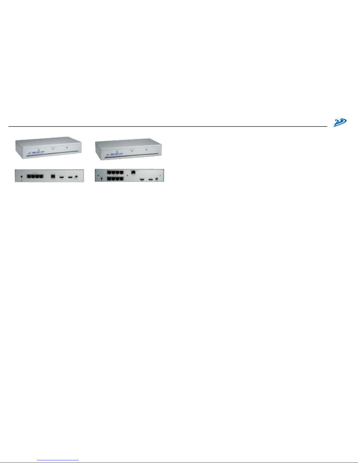
HDM I –E1 04 C
4-P or t H DM I Tr an sceiv er
HDM I –E1 08 C
8-P or t H DM I Tr an sceiv er
Page 5

User Manual
8
9
2. HDMI-E104C and HDMI-E108C Transceiver
3. HDMI Cable and Cat5 HDMI-RJ45 Receiver
/
Panel Description
1. HDMI-E102T Transmitter and HDMI-E102TR Transceiver
❶
❸❷
❹
❺
Lin k Ind ic ator of Lo ca l M on ito r (MI)
❻
HDM I Out pu t for Loca l Mon it or (M I)
❼
HDM I Inp ut (Use HDMI c onn ec tor )
❽
RJ- 45 HD MI Inpu t
❾
Lin k Ind ic ator
❿
Pow er In di cator
❶
Vid eo EQ Cont ro l
❷
Pow er Ja ck
❸
RJ- 45 HD MI Outp ut
❹
EQ In dic at or
LED O N : Au to EQ
LED O ff : Man ua l
❻ ❼ ❽
❺
To HD MI Pl ay er To HD MI In pu t o f Tran sm itt er
❹
❶
❸❷ ❻
❺❹
❹
❿❾
❶ ❸❷
❼
EQ In dic at or
LED O N : Au to EQ
LED O ff : Man ua l
❽
HDM I Out pu t
❾
HDM I Inp ut
❿
Vid eo EQ Cont ro l
❶
EDI D A cti vi ty
❷
Lin k of Lo cal M onito r
❸
Pow er In di cator
❹
Pow er Ja ck
❺
RJ- 45 HD MI Outp ut
❻
RJ- 45 Sy st em Li nk Ou t
❻ ❽❺❹ ❿❾
HDM I- HR
HDM I- RJ4 5 Recei ver
❶ ❸❷
❻ ❽❺❹ ❿❾
❼ ❼
HDM I Cab le (for Play er )
HDM I Out pu t
RJ- 45 HD MI Iutp ut
Page 6

User Manual
10
11
(7) LINK OUT: HDM I signal can be extended/ca sc ad ed over “LINK
OUT” port by Cat5/5e/6 FTP cable, please refer to “Selection and
Preparation of Cat5/5e/6 cable.” The signal can be received by
following three ways (A), (B) and (C):
A. H DMI-HR: T he HDMI dist ance can be extende d is: < 30m. f or
480p/720p/1080i, or < 15m. for 1080p. (Distance is based on FTP
cable skew < 15ns/100m).
B. “LINK IN” of HDMI-E102TR: Typical cascaded distance is: < 80m. for
480p, < 70m. for 720p/1080i, or < 30m. for 1080p. (Distance is based
on FTP cable skew < 15ns/100m). The installation of HDMI-E102TR
is described in next section.
C. “HDMI IN” of HDMI-E104C/HDMI-E108C: To connect to the HDMI
conn ector, a HDMI-H R Rec eiver i s req uired . Typical cascade d
distance is: < 80m. for 480p, < 70m. for 720p/1080i, or < 30m. for
1080p. (Distance is based on FTP cable skew < 15ns/100m).
/
Installation and Operation
1. Install HDMI-E102T Transmitter:
(1) Firs t Time Set-up: P le ase turn off the HDMI output dev ice and
monitors.
(2) Device Connection: Connect local HDMI monitor (M1) to the “HDMI/
M1 OUT” of the transmitter and take the HDMI cable, plug one end
to “HDMI IN” port of transmitter and the other end of the cable to the
HDMI output port of HDMI output device.
(3) Connect the power adaptor to the “DC5V” and plug into the power
outlet.
(4) System Turned On: Turn on your HDMI output device and monitor to
conrm the function of display. The “M1 LINK” LED of the transmitter
should turn on orange to reflect t he conn ection of a local HDMI
monitor.
(5) Other Monitors: Please make sure the other HDMI monitors used in
Transceiver can also display the video resolution broadcasted.
(6) EQ Adjustment: In most of the cases, you can adjust the EQ control
to Auto mode by rotate the EQ to the left side and the “EQ” and ”
Auto” LEDs will turn on blue. If you see some dynamic dots or unclear
image on the HDMI monitor, it reflects the HDMI signal received by
Transmitter need to be adjusted. Then you can adjust the EQ control
for better image display, it will turn the EQ into manual mode, the “EQ”
and ”Auto” LED will turn off to indicate the manual EQ mode.
HDM I
Pla yer
HDM I Trans mitte r
Pow er Adap tor
HDM I
Con ne cti on of H DMI Tr ansmi tt er
Thr ee Wa ys of Ex te ndi ng HDMI Sign al fr om HD MI Tra ns mitte r
Power Adapto r
HDMI
Cat5/5 e/6 Cable ( Long Dista nce)
HDMI Transc eive
HDMI Transmi tter
HDMI Playe r
HDMI
HDMI
HDMI
A B C
HDMI
Multi- Port HDMI
Transceiver
X 8
Power Adapto r
Power Adapto r
Cat5/5 e/6 Cable (Sh ort Dis tance)
Cat5/5 e/6 Cable
(Short D istance)
Page 7

User Manual
12
13
2. Installation of HDMI-E102TR Transceiver:
(1) Mo nito r Co nnec tion : Co nne c t H D MI moni t or’s HDM I ca ble to
Transceiver and turn on the monitor.
(2) Device Connection: Plug power adaptor to HDMI-E102TR, the “PWR”
LED and “M1 LINK” will turn ON, the other “LINK” LED should turn off,
since there is no input of video signal from “LINK IN” port.
(3) HDMI Cascading: The RJ-45 “LINK IN” port is designed to receive
the HDMI signal from Transmitter over Cat5/5e/6 FTP cable, follow
previous section to install Transmitter and extend the HDMI signal
here.
(4) EQ Adjustment : In most of the cases, you can adjust the EQ control
to Auto mode by rotate the EQ to the left side and the “EQ” and ”
Auto” LEDs will turn on blue. After connecting the expander system, if
you see some dynamic dots or unclear image on the HDMI monitor, it
reects the HDMI signal received by Transmitter need to be adjusted.
Then you can adjust the EQ control for better image display, it will turn
the EQ into manual mode, the “EQ” and ”Auto” LED will turn off to
indicate the manual EQ mode.
(5) LINK OUT : The function of “LINK OUT” port on Transceiver will act
the same as Transmitter’s. It can extend/cascade HDMI signal to (A)
HDMI-HR Receiver, (B) another one-port HDMI Transceiver or (C)
4/8-port HDMI Transceiver as following illustration.
HDM I
Pla yer
HDM I Trans mitte rHDM I Trans ceive r
Cat 5/5e/6
Pow er Adap tor Powe r Adapt or
HDM I HDM I
HDM I Trans ceive r
Pow er Adap tor
HDM I
Con ne cti on of H DMI Tr ansce iv er
Power Adapto r
HDMI
Cat5/5 e/6 Cable ( Long Dista nce)
HDMI Transc eive
HDMI Transc eive
HDMI sig nal
receive d from
Expande r
System
HDMI
HDMI
HDMI
A B C
HDMI
Multi- Port HDMI
Transceiver
X 8
Power Adapto r
Power Adapto r
Cat5/5 e/6 Cable
(Short D istance)
Thr ee Way s o f E xte ndi ng HDMI S ignal fr om HDMI Tr ansmi tte r
Page 8

User Manual
14
15
3. Installation of HDMI-E104C / HDMI-E108C Multi-port Transceiver:
(1) These two models have the same function and are only different in the
amount of RJ-45 HDMI output.
(2) Monitor Connection: Connect HDMI monitor’s HDMI cable to Multi-port
Transceiver’s “HDMI/LOCAL OUT” port and turn on the monitor.
(3) Device Connection: Plug power adaptor to Multi-port Transceiver,
the front panel’s “POWER” LED and “LOCAL LINK” will turn ON, the
“ACTIVE” LED will turn ON till Transceiver has received active HDMI
signal.
(4) HDMI Sources: The “HDMI IN” can receive HDMI signal from (A)
standard HDMI output device or (B) HDMI-E102T / HDMI-E102TR /
HDMI-E104C / HDMI-108C by using a HDMI-RJ45 Receiver.
(5) EQ Adjustment: In most of the cases, you can adjust the EQ control
to Auto mode by rotate the EQ to the left side and the “EQ” and ”
Auto” LEDs will turn on blue. After connecting the expander system, if
you see some dynamic dots or unclear image on the HDMI monitor, it
reects the HDMI signal received by Transmitter need to be adjusted.
Then you can adjust the EQ control for better image display, it will
turn the EQ into manual mode, the “EQ” and ”Auto” LED will turn off
to indicate the manual EQ mode.
(6) LINK OUT: The function of “LINK OUT” port on Multi-port Transceiver
is used to cascade HDMI signal to (A) one-port HDMI Transceiver or
(B) another 4/8-port HDMI Transceiver as following illustration.
Mul ti-por t HDM I Tr ans cei ver
Pow er Adap tor
HDM I
Con ne cti on of M ulti- po rt HD MI Tra nsc ei ver
Cat5/5 e/6 Cable ( Long Dista nce)
HDMI Transc eive
Standar d HDMI Out put Devic es:
> HDMI Spl itter/Se lector
> Video gam e consol e
> Media PC, c omputers
> Set top boxes
> DVR,DVD p layer, and soon
HDMI
HDMI
Multi- Port HDMI
Transceiver
X 8
Power Adapto r
Cat5/5 e/6 Cable
(Short D istance)
HDMI Cab le
HDMI Transmi tter
Multi- Port HDMI Transcei ver
Con ne cti ng of H DMI S ou rce s
Power Adapto r
HDMI
Cat5/5 e/6 Cable ( Long Dista nce)
HDMI Transc eive
HDMI Out put
Source s
HDMI
HDMI
HDMI
A B
Multi- Port HDMI
Transceiver
X 8
Power Adapto r
Power Adapto r
Two Ways of Cascading HDMI S ignal by Multi-p ort HD MI Transmit ter
Multi- Port HDMI
Transceiver
Cat5/5 e/6 Cable
(Short D istance)
Page 9

User Manual
16
17
(7) Connecting Monitors: 4/8 HDMI monitors can be connected to the
“RJ-45 HDMI OUT” ports by adapting a HDMI-HR Receiver.
(8) Additional System Expansion: The “RJ-45 HDMI OUT” port can also
be used as link out port for more system expansions.
4. Selection and Preparation of Cat5/5e/6 FTP cable:
(1) Selection: Most makes and versions of current Cat5/5e/6 cables will
work with the DVI-E102T Transmitter and DVI-E102TR Transceivers.
However since the quality and characteristics of Cat5/5e/6 cable
varies it has been found that some perform better than others, even if
they cost lower. The major factor inuencing the transmitting distance
is the skew property of the cables. Skew represents the difference in
propagation delay between the fastest and slowest set of wire pairs.
A lower skew will mean a longer video transmitting distance.
(2) Skew Property: A Cat5/5e/6 cable with a skew lower than 15ns/100m
should enable a cascading length of <80m. at 480p resolution, <70m.
at 720p/1080i resolution and <30m. at 1080p resolution. Some cable
types may not have a known skew so it is best to test for maximum
practical distances before starting the installation.
(3) For some installations where the potential for interference exists the
FTP type of Cat5/5e/6 cable is recommended.
(4) The RJ-45 terminations to the Cat5/5e/6 cable must be made to the
EIA 568B specications.
(5) Connecting the Cat5/5e/6 FTP cable: Plug one end of the cable
to the Transmitter’s “LINK IN/OUT” port and the other end to the
Transceiver’s RJ-45 “LINK IN/OUT” port. The monitor connected to
the Transceiver should now display and the “LINK” or “ACTIVE” LED
should turn green to indicate the HDMI signal activation. Adjust the
“EQ” control for best quality HDMI display.
Mul ti-por t HDM I Tr ans cei ver
Pow er Adap tor
HDM I
Con ne cti ng 8 HD MI Mo ni tor s
HDM I
Cat5/5 e/6 Cable
(Short D istance)
X 8
1 2 3 4 5 6 7 8
JAC K POS IT ION
PAIR 1PAIR 2 PAIR 4
PAIR 3
The EIA/ TI A de fi nat io n o f 568B in th e pin a ssi gn ment is
(1) o range whit e, (2 ) ora ng e, (3 ) gre en wh it e, (4 ) blu e,
(5) b lue w hite, ( 6) gr een , (7) b rown wh ite , and ( 8) br own
Page 10

User Manual
18
19
/
Specification
/
Remarks
1. Please read this operation manual carefully before installing the system.
2. Please use high quality Cat5/5e/6 cable for optimum results.
3. To prevent potential power damage do not use 2-wire extension cord.
Ensure AC outlets at PCs and displays are on the same phase and have
correct and common grounding.
4. Limited Warranty:
(1) In no events shall the vendor’s liability for direct or indirect, special,
incidental or consequential damages, loss of prot, loss of business,
or financial loss which hay be caused by the use of the product
exceeds the price paid for the product.
(2) The vendor makes no warranty or representation, expressed or
implied with respect to the contents or use of this documentation,
and especially disclaims its quality, performance, merchantability, or
tness for any particular purpose.
(3) The vendor also reserves the right to revise or update the product or
documentation without obligation to notify any user of such revisions
or updates. For further information, please contact your direct vendor.
HDM I
Pla yer
HDM I Trans mitte rHDM I Trans ceive rH DMI Tr ans cei ver
Cat 5/5e/6 Cat 5/5e/6Cat 5/5e/6
Pow er Adap tor Pow er Adap tor Powe r Adapt or
HDM I HDM I HDM I
Con ne cti on Diag ram o f HDM I Exp an der
5. Installing More Transceivers and Displays:
(1) Using additional Transceivers and Cat5/5e/6 FTP cable it is possible
to extend the system almost indefinitely to remote HDMI displays.
For a large group of cascaded Transceivers, please ensure common
grounding is maintained to minimize ground-loops and interference.
(2) A HDMI splitter or distribution amplier may be used at each HDMI
output to drive additional local HDMI displays.
Model
Cat5 HDM I
Transmitter
HDMI- E102T
Cat5 HDM I Transceiver
HDMI- E102T R
HDMI- E104 C HDMI- E108 C
Input HDMI Fema le x 1 RJ-45 x 1 HDM I Female x 1 HDMI Fema le x 1
Output
HDMI Fema le x 1
RJ- 45 x 1
HDMI Fema le x 1
RJ- 45 LINK Out x 1
HDMI Fema le x 1
RJ- 45 HDMI Ou t x 4
RJ- 45 LINK Out x 1
HDMI Fema le x 1
RJ- 45 HDMI Ou t x 8
RJ- 45 LINK Out x 1
Max Dist ance
and Resolu tion
480p wi th each cas cading le ngth < 80m, 7 20p/1080 i with each cascad ing length < 7 0m
1080p wi th each cas cading len gth < 30m
Video Co ntrol EQ x 1
Signal Type HDMI
Power Cons umption DC5V , 750mA DC5V , 750 mA DC5 V 1.8A DC5 V, 2.5 A
Housing Metal
Dimensi on
(LxWx H) mm
Compact S ize, 62 x 113 x 29 1U He ight, 240x18 0x44
Page 11

 Loading...