

Page 1

Super Mini AV Extender
Analog Media
Product
User Manual
AVE-M180T
AVE-M180R
Page 2

User Manual
2
3
One-Port Mini Transmitter : AVE-M180T
One-Port Mini Receiver : AVE-M180R
(C) 2006 Green -Box Tech nolog y Co ., L td.,
All Rig hts R eser ved
Res erves in th e ha rdwar e, p acking and acco mpany
doc umenta tion with out p rior writt en no tice .
TABLE OF CONTENTS
Package Contents
Introduction
Key Features
Panel Description
Installation and Operation
Specication
Remarks
4
4
4
5
6
10
11
Page 3
User Manual
4
5
7. Transmitter and Receiver build with LEDs to indicate system status
8. Transmitter takes DC5V power from USB port
9. Receiver build in EQ to adjust image quality
/
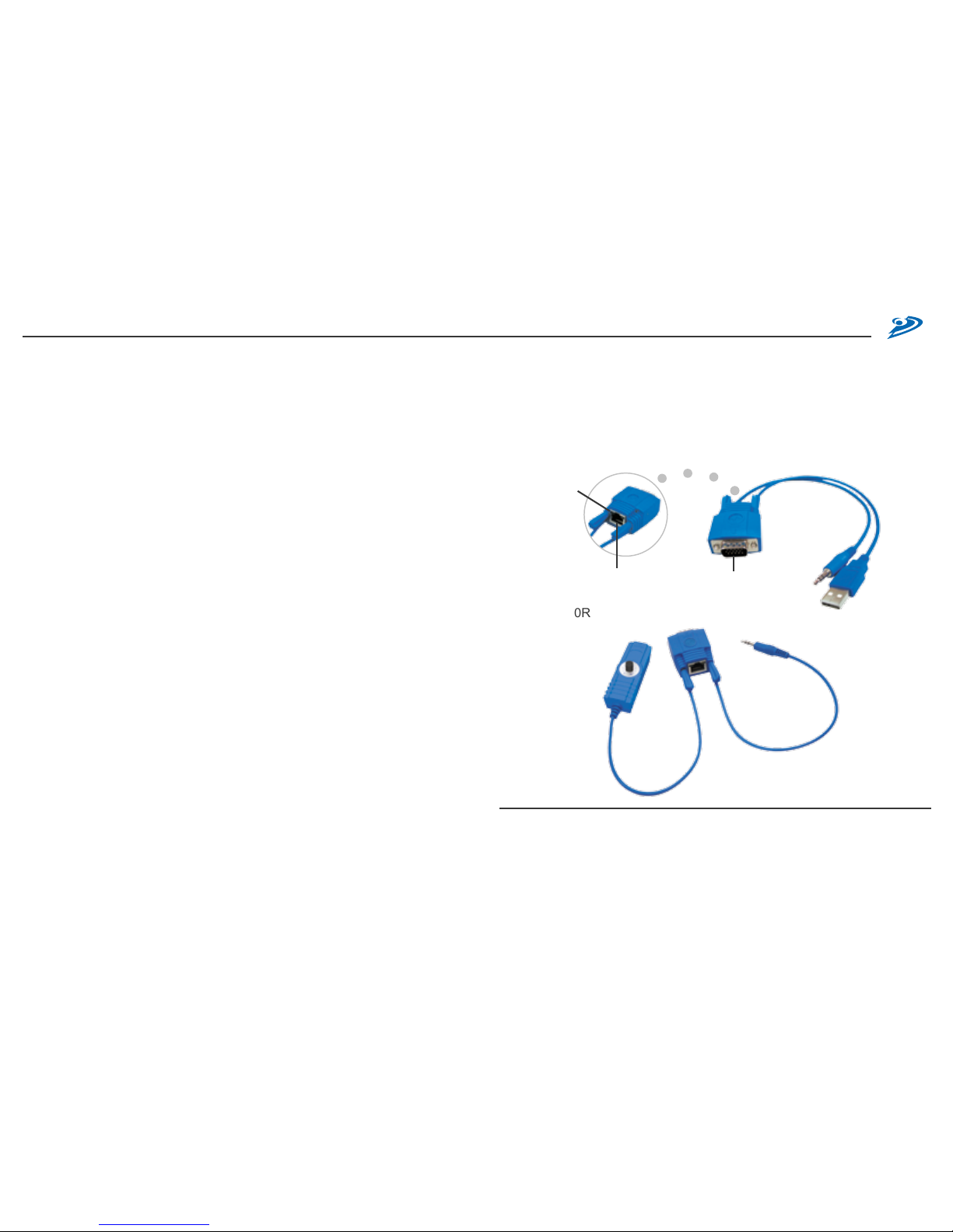
Panel Description
AVE-M180T
AVE-M180R
/
Package Contents
A. AVE-M180T: One-Port AVE-M180 Super Mini AV Extender Transmitter
1. AVE-M180T x 1
2. M-F VGA connector x 1
3. User Manual
B. AVE-M180R: One-Port AVE-M180 Super Mini AV Extender Receiver
1. AVE-M180R x 1 3. M-F VGA cable x 1
2. AC7.5V Power Adaptor x 1 4. User Manual
/
Introduction
AVE-M180 is the smallest AV Extender in the industry; the main body is
as big as a VGA connector and able to transmit VGA + Audio by a single
Cat5e cable up to 180m. With its simplied design, you can install the
extender very easily and save space. You can use it to broadcast AV
signal from PC, KVM switch, matrix AV switcher and applied in the device
extension of projector, plasma TV, LCD TV, LCD monitor, HDTV, and
CRT. It can also be integrated with splitter and selector to fulll different
AV application.
/
Key Features
1. This syst em can send VGA and Audio sign al from Transm itter by
Cat5/5e/6 cable, and broadcast to Receiver. The standard maximum
broadcasting distance is 180m
2. Compact design with VGA and Audio transmit function
3. Maximum supported distance and resolution: 2048x1536@180m
4. Use Cat5 Enhance UTP cable (350MHz bandwidth) for better quality
5. Software free, pure hardware design, support Plug & Play
6. Support VGA, SVGA, XGA, TFT_LCD, LCD TV, PDP, Projector with
DDC2B function
❶
To VG A Ou tpu t
❷
To Aud io Out put
❸
To US B P owe r(D C5V )
❹
Rj- 45 Sys tem Li nk
❺
V&H Sy nc A cti vit y
B lin kin g : No si gna l L ED ON : Active
❻
Vid eo Foc us
❼
Pow er Jac k
❽
To Mo nit or
❾
To Sp eak er
❻
❼ ❽
❾
❹
❺
❶
❷
❸
❹
❺
Page 4

User Manual
6
7
/
Installation and Operation
1. AVE-M180T Single-Port Transmitter Installation:
(1 ) C onn ec tin g Tr ans mit ter : Tak e AVE -180T a nd conn ect u vw to
computer’s VGA, Audio and USB port. The Transmitter will take the
DC5V power from computer’s USB port and if your computer or VGA
player doesn’t have USB port, please prepare optional power adaptor
with a USB power output to supply the power.
In sta lla tion Diagram of Sys tem Tra nsm itt er AVE -M1 80T
Op tio nal Power Adap tor wi th a U SB 5VD C p owe r o utp ut
(2) Function Test: Turn on your PC or VGA player, the LED of Transmitter
will blink before VGA signal is turned ON and remain ON after VGA
signal is turned ON.
(3) Some PC might have tight space to connect AVE-M180T to VGA port,
you may take one short male-female VGA connector to connect in
between AVE-M180T and VGA output port.
2. Receiver AVE-M180R installation and UTP Connection
(1) Power Up: Plug power adapter to the Receiver and connect to monitor
and speaker. The LED above RJ-45 port should blink to indicate the
unconnected status of AV signal.
You can also use a short VGA cable (in the package) to connect in
between Receiver and monitor and place the receiver in other place.
VGA
Aud io
USB
Opt ion al VGA Cab le
Vid eo Mon ito r & Sp eaker
Pro jec tor PDP LCD CRTTV
VGA
Aud io
USB
M-F VG A Co nne cto r
Page 5

User Manual
8
9
(2) Selection of UTP Cable: For best VGA resolution, please use Cat5
Enhanced cable (350MHz bandwidth), the maximum extended length
of one section (one pair of Transmitter or Receiver) should not exceed
180 meters. The connector must be made by 568B/568B type.
T he EIA /TI A definatio n o f 5 68B in th e p in ass ign men t i s
( 1) ora nge wh ite , ( 2) ora nge , ( 3) green whit e, (4) bl ue,
( 5) blu e w hit e, (6) gr een , ( 7) brown white, and (8 ) b row n
(3) Connect UTP Cable: Plug two ends of UTP cable to Transmitter
and Receiver’s RJ45 SYSTEM LINK ports, the monitor and speaker
connected to Receiver should work now and the LEDs above RJ-45
port should remain ON. You can adjust the FOCUS control of Receiver
to have the best VGA display.
I nstallation D iag ram of Re cei ver AVE-M 180 R
(4) Function Test: After above installation, you will be able to broadcast the
AV signal to Receiver’s connected monitor and speaker.
(5) Problem and Solving: If you find unstable image or audio problems
after installation, please confirm following list or contact your direct
vendor for further assistance:
a. Check if PC’s VGA resolution and frequency over the limit of monitor
display, if so, please change the VGA configuration from Windows
Control panel.
b. Try to connect Monitor and speaker directly to a PC, and ensure the
basic function of these devices.
c. When using LCD or same type monitor, there might have some image
offset or blinking, please adjust the position, clock or phase of the
LCD monitor, or simply press Auto Adjust / Tune to have a better
image solution.
3. Other Integration and Application:
Please contact your local dealer or distributor for further information.
1 2 3 4 5 6 7 8
JAC K P OSI TIO N
PAIR 1PAIR 2 PAIR 4
PAIR 3
One -Po rt
min iTransm itt er
One -Po rt
min i R ece ive r
Vid eo Mon ito r & Sp eaker
Use Ca t5e /5e /6
cab le up to 180 m
Pro jec tor PDP LCD CRTTV
VGA
Aud io
USB
Page 6

User Manual
10
11
/
Remarks
(1) Before operating this system, please read operation manual carefully.
(2) Please use correct power ad apter and use high quali ty cable for
optimum broadcasting.
(3) To prevent potential power damage, please don’t use 2 -wire extension
cord and ensure AC outlets at relative devices on the same electronic
phase and have correct grounding.
(4) Limited Warranty :
A. In no events shall the direct vendor’s liability for direct or indirect,
special, incidental or consequential damages, loss of profit, loss of
business, or financial loss which may be caused by the use of the
product exceeds the price paid for the product.
B. The direct vendor makes no warranty or representation, expressed
or implied with respect to the contents or use of this documentation,
and especially disclaims its quality, performance, merchantability, or
tness for any particular purpose.
C. The direct vendor also reserves the right to revise or update the
product or documentation without obligation to notify any user of such
revisions or updates. For further information, please contact your
direct vendor.
/
Specification
Mod el AVE-M 180T AVE-M 180R
Des cripti on Sup er Min i AV Tran smitt er Sup er Min i AV Rec eiver
AV In put VGA x 1, Audio x 1 RJ45 x 1
AV Ou tput RJ4 5 x 1 VGA x 1, Audio Mono x 1
Vid eo C TRL - Vid eo E Q
LED Pow er and Video Stat us
Vid eo Q uali ty Max imum VGA R esolut ion a nd D istan ce : 2048x 1536@ 180m
Pow er Con sumpt ion US B DC 5V Po wer, 200m A AC7 .5V, 25 0mA
Env ironme ntal Cond ition
* O perati on Temp. : 0~5 0 * Stor age Temp .: -2 0~60 degre e C
* H umidit y: 10 ~90%
Page 7

 Loading...