

GreenAire RAH-SAU series Installation And Operation Manual

INSTALLATION AND OPERATION
FOR:
RAH–SAU Series
VS.7.14
1

1. Equipment provided
: Locate all equipment provided with your order. The following
make sure to look at your packing slips and purchase orders
to determine exactly what is included in your system.
Generator Control Panel
Reverse Osmosis system
Governing humidity
Installation and Maintenance Manual
Location of the humidifier
Installer. The following rules should be followed:
Place the Control Panel in a place where the outlet fog will
surfaces. Make sure to verify the air patterns in the room to preclude any adverse
flows that would cause the fog to impinge upon any walls, the control cabinet or
If the unit is feeding a test chamber or room then
cabinet as close as possible to the dispersion point of the fog and no greater than
10’ ft. if possible. The longer the run of discharge tubing the more your losses of
fog will be. (Consult with the Factory if thi
Location and Piping:
ocate
the dispersion point
Make sure the Control Panel
tubing to the inlet and outlet stubs on the Control Panel make
sure they are water tight.
Sealant can be used on the
adhesive because these tubes will need to be loosened during maintenance.
When piping try to avoid creating
piping. If you cannot avoid doing so then
(if applicable)
is the preference of the End User or
not impinge on any
try and keep the control
’ ft of equivalent piping
is installed LEVEL! VERY IMPORTANT!
water “traps” or low points in the
drain from such
equipment may be provided –
a.
b.
c.
d.
2. Humidifier location:
A.
other surfaces.
B.
including 4 gal. storage tank
sensor
s is a problem
INSTALLATION:
I) Control Panel
A. As stated above l
distance from
B.
C. When attaching
D.
CAUTION:
trap locations. (see Fig. 1 )
the Control Panel within 10
.
stubs if desired for complete seal.
be sure to plumb a mini-
But not
2

E.
Pipe the drain line
Again be sure not to trap water. If necessary employ a condensate pump/drain to
elevate the drain water and evacuate it during drain cycles.
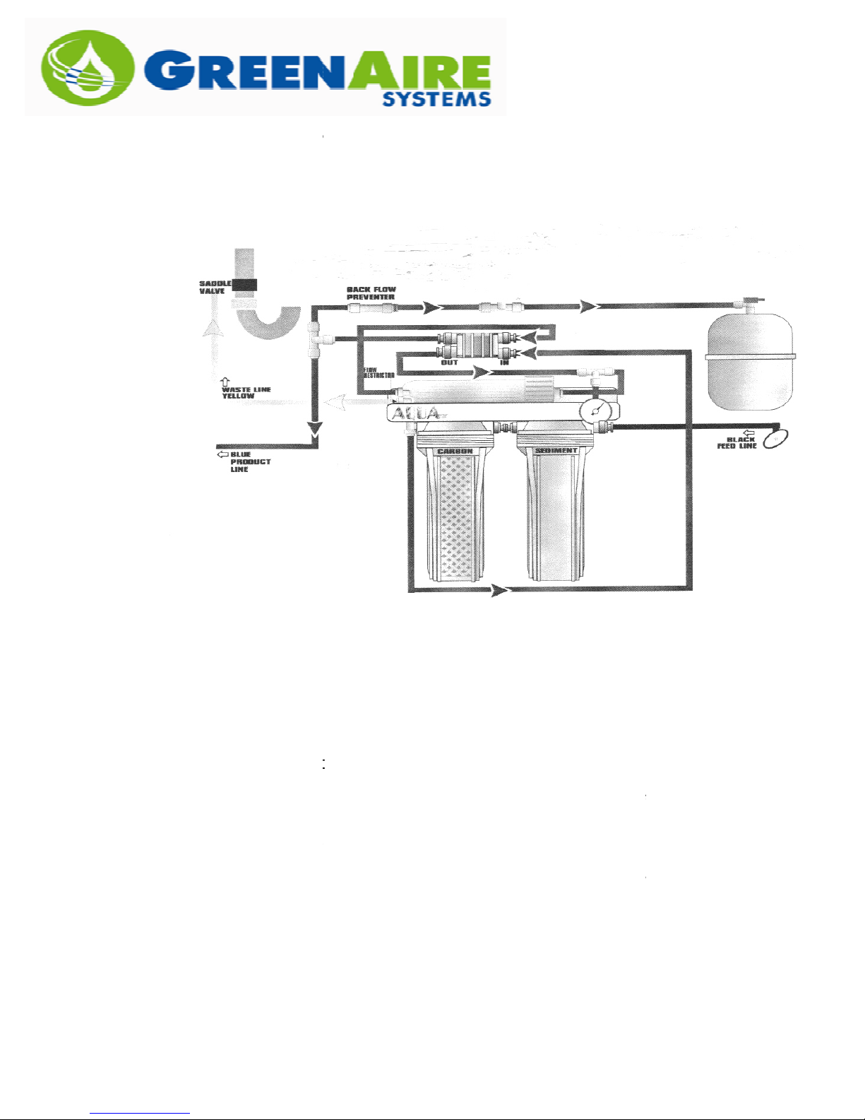
II) RO System Location and Piping:
everse
mountable with simply two screws and can be hung as self supporting. Follow
outlined below
respective connections. All connections are simple quick connec
recommended that a shut off valve be placed in line after tapping the domestic
water line for the RO System supply.
Locate and connect the
quipment. This will be the right side as you face the system. The
ply side will consist of Black ¼” tubing.
Locate the Yellow drain line, and place in an appropriate area for
drainage.
HUMIDIFICATION SEASON IS MONTHS AWAY.
CONDENSATE PUMP
Locate the b
humidifiers
system metal frame)
storage tank.
proximity to the RO System.
Make sure to open the valve at the top of the storage tank.
Once installed, allow the system to run for approximately 15
minutes to flush completely. Make sure there are no leaks, parts
can come loose in shippin
The RO System will run until all the humidifier supply lines and
storage tank are filled and charged to the pressure of the building.
This may take several hours to happen.
PLEASE N
WATER SUPPLY TO THE RO SYSTEM.
if this is a problem)
Pipe supply piping from
or STS Box
Open the inline water valve off of the build
filling of water to the
filling the clear water filter housings on the RO System.
As stated above The RO System will run until all the humidifier
lines and storage tank are filled and charged to the pressure of the
building. This may take several hours to happen. Again, make sure that the
if the drain line is fed to a condensate pump the pump MUST
The RO System h
to an appropriate drain location.
Water system. These systems are wall
for connecting the colored tubes to their
supply side of the
NOTE: DRAIN MUST BE OPERABLE! EVEN IF THE
e product water line that will provide
(provided and taped to the RO
to hook up the product water (blue line) to the
Locate the 2.5 gallon storage/bladder
g. Hand tightening may be necessary.
OTE: 35 PSI MINIMUM REQUIRED ON INCO
(Consult with the Factory
the RO System to the fitting on the side of the
ing domestic water supply to begin
System. You should notice water immediately
as an automatic shut off valve (ASO) that
from the Control Panel
A. Now install the R
the instructions
1)
e
sup
2)
3)
4)
5)
Osmosis (RO)
domestic water
– IT MUST BE ON LINE!
lu
. Utilize a “t” connector
ts. It is
IF PIPED TO A
RO water to the
tank in close
6)
7)
B.
Panel/Generator
labeled “water in”.
C.
the
RO
D. Check for leaks.
supply
drain is working –
BE OPERABLE!
MING
Control
3
is completely mechanical and will only open and pass water to drain when the
pressures are not equalized between the domestic water supply and the
humidifier supply lines. If there are any questions or issues plea
Factory Representative.
If the system was provided with a controlling humidity sensor then install it
and wire it from the Generator panel at the appropriately labeled locations on
the terminals. Refer to the Wiring
landing locations and line sizes.
Do the same as the above with both the High Limit humidistat and the Air
Flow switch if provided. Terminal locations are
Diagram provided with your Unit.
S signal is being provided then connect it to the proper terminal
locations in the Generator as labeled in the Wiring Diagram provided with the
In this case a separate 24VAC signal is required to turn on the
provided with your unit for proper
ded control wire is recommended but
again labeled in the Wiring
locate AFS before any
se contact your
III) Accessories:
A.
not required.
B.
dampers.
C. If a BA
Unit.
humidifier.
Diagram
Shiel
CAUTION:
zone
4

IV)
Start Up Procedure:
Verify Piping connections
double check the inlet and outlet water connections to the system
either at the generator panel or at the S
open up any shut off valves up stream to the water inlet and make sure
that, with the water charged, there are no leaks while the System is off.
now check the fogging inlet and outlet connections from the UPC t
(these are typically 3” or 2” connections). Make sure that the hose
couplings are tightened.
evaluate the installing contractor’s piping from the fogging outlet
connection to the DTA and make sure it isn’t excessively long (in
excess of 10’) and
where condensate can accumulate without a drain. (please note
typical steam piping practices should be utilized when piping a fogging
supply line; i.e. don’t create traps and do use the manufacturers
mmended pipe size)
if a vertical header DTA was used make sure the drain connection at
the bottom of the header has been connected to a drain.
Turning the System On:
go to the control panel and make sure the panel on/off switch is off.
open up the
if CB is showing green then the CB is in the ‘off’ position. If it is
showing ‘red’ it is in the ‘on’ position and power will pass through the
now remove the fuse on the 48VAC transformer a
place it nearby.
verify that the 120V line to the panel is connected and live.
verify that the Air Flow switch is installed and wired appropriately to the
proper terminals in the control panel (see wiring diagram that came
with the pan
verify that the Hi
the proper terminals in the control panel (see wiring diagram that came
with the panel and/or was submitted for that job)
verify that the controll
been installed and has been wired back to the proper terminals in the
control panel (see wiring diagram that came with the panel and/or was
submitted for that job)
verify that the AC System to which the humidifi
and running. Make sure it is running at the expected speed and
volume as scheduled in the Submittals and on the Humidifier
Schedule. If the volume (CFM) is more than 20% different than what
was planned for during the design and s
TS box. Connections should
that no ‘traps’ have been created in the piping
control panel and make sure the circuit breaker (CB) is off
nd hold on to it or
Limit switch is installed and has been wired back to
ing humidity sensor (if supplied by GAS) has
er is connected to is on
izing of the humidifier please
A.
1.
2.
3.
4.
5.
B.
:
–
be tight.
ank
–
reco
1.
2.
–
3.
4.
5.
6.
7.
8.
CB.
el and/or was submitted for that job)
-
5

call the Factory. Also make sure that the Cooling Cycle/Coil is off and
not operating when the humidifier is on. Remember
will be running in the winter time/heating season so in most cases the
cooling coil
are year around cooling loads
taken to turn off the cooling coil or control it differently than normal
when integrating a humidifier into the System.
9. Take
the wet switch safety and place it temporarily off the floor of the
Panel or STS Box. There should be enough of a tether on the wire
harness to allow you to hang it outside the panel/STS box or to hang it
at a higher position temporarily. Some models no
thick small section of plexiglass as a permanent resting plate for the
wet switch. If this is present then none of the above is required and
the Wet Switch can remain in it’s normal position.
now turn the CB into the ‘on’ position.
rn on the panel door on/off switch. It is a lighted switch so it
should light up when in the ‘on’ position.
with the panel turned on, if there is a controller provided with the
system it should become active and show figures on it’s display. The
should correspond to both the actual humidity level and the
target set point humidity level. Make sure their respective readings
make sense and seem accurate for the time of year you are
conducting this start up.
oller go to the section in this Manual titled Controller.
Assuming you have relevant readings on the controller raise the Set
Point humidity level to above what the actual humidity level is reading.
This is especially important when starting up the Syst
warmer or summer time conditions. For example
reading 58%Rh in the target space and your humidity winter
time/heating season target is 35%Rh then the Controller will not
energize the System to produce fog because the actua
humidity is 23 points above target. In this scenario you must adjust the
set point to an artificially high set point in order for the controller to
energize system.
Once the controller is in a ‘call for humidification’ mode and the target
humidity set point is higher than the actual humidity level then the
system should begin preparing to humidify.
Verify that water has begun to flow into the UPC tank. You should
have heard the solenoid valves energize. You can also check by
opening up t
model type.
Verify that the Wet Switch is showing a ‘green’ lite.
Verify that there are no leaks in the tubing within the Panel or STS box
as the water fills. (tubing may have gotten loosened
installation
would not be on. For some applications and facilities there
if this is the case then care must be
w come with a ¼”
For more details and specifics on the
em during
if the controller is
he top latches of the UPC tank if it is a side inlet and outlet
during shipping or
all Systems are live tested before they ship from the
10.
11. now tu
12.
figures
–
the humidifier
–
13.
14.
15.
16.
17.
Contr
–
l space relative
–
Factory)
6

18.
Depending on what kind of water pressure is available in the Facility,
the System should take about 3
proper level for fog
the green panel lite labeled ‘Fog On’ will lite up.
When the green ‘Fog On’ lite come on
On/Off Switch on the panel door and at the CB. Now re
der on the 48VAC transformer. Go ahead and turn on the
CB and On/Off switch on the Panel Door.
You should now hear, when standing very close to the UPC Tank, the
System operating. It should sound like water bubbling within the tank.
If this is the case
operating properly.
check the Panel or STS Box for any leaks
Now go to an air diffuser on the AC System being humidified and take
a humidity reading. It should read several point
space RH is.
Now several additional tests need to be done prior to completion of the
(a) Have the AC System turned off and verify that the Humidifier turns
off as well as air flow stops.
(b) With the AC System back on, if pos
and lower its setting to as low as it can go. The switch should open
and cause the humidifier to shut down. Verify that this is the case.
Then raise it back up to 75%Rh setting. The System should come
the System is turned off the water from the UPC tank should
slowly drain out of the tank. Verify that this is indeed happening with
the System off.
(d) If an artificially higher target humidity set point was used for the
controller then lower the target
setting and verify that the humidifier de
(e) When the system is off and draining and has been doing so for
several minutes, verify that there no continuity between terminal 15
and 10. (for
connections on Relay 3). If there is
measuring the continuity again. When the tank has largely emptied
then 15 and 10 should have no continuity. If there is still contin
the Factory and do NOT turn the system on again.
Allow the System to run for a while. Anywhere from 30 minutes to 1.5
hours when starting it up. Or if it is during the heating season and
there is currently a need for humidification then leave t
Finally, make sure the Wet Switch is back in it’s location and showing a
‘green’ lite.
7 minutes to fill the tank to the
generation. When it does reach the proper level
turn off the System at both the
then you are generating fog and the system is
there should be none.
s above what the
sible, locate the HiLimit switch
humidity set point back to it’s normal
energizes appropriately.
earlier models you can measure this right at the coil
wait awhile longer before
–
19.
into it’s hol
20.
21. Re-
22.
23.
Start Up.
back on.
(c) When
–
-insert the fuse
–
–
24.
25.
-
uity call
he system on.
7
 Loading...