


INSTALLATION AND OPERATION
FOR:
R
Initial items …………
Humidifier basics……
Installing humidifier
Sequence of
Typical System Diagrams
STS System Diagrams….
Wiring diagram
Trouble Shooting
Mainte
Controller info
Wet Switch ………………
Parts List …………………
More Components ……..
AH – 1000 & 1500 Series
Table of Contents
..… 1
… 2
…… 3
Operation .. 6
7
9
s …………. 12
……….. 15
nance …………… 17
………….. 18
VS.10.13
21
22
23
1

1. Equipment provided
: Locate all equipment provided with your order. The following
make sure to look at your packing slips and purchase orders
to determine exactly what is included in your system.
trol Panel
Control Panel only (for STS units only)
Dispersion Tube Assembly
STS (Split Tank System) Box
Reverse Osmosis system
Governing humidity sensor
Installation and Maintenance Manual
Location of the humidifier
the location shown by the Design Engineer in the Project drawings. The following
guidelines should be adhered to:
The DTA should be placed in
) feet up stream and downstream with no obstructions, branch take offs or
If a vertical section of duct is chosen make sure to slightly angle the DTA
that all condensate will pitch back to the header tube.
rule applies for obstructions as stated previously.
The Generator should be located in close proximity to the DTA. Locations
ld not be located further than 1
For the STS systems the STS Box should be located as near as possible to
the receiving air duct and DTA. The Control Panel for STS systems may be
located as far away as 40 ft. (please consult with your local Rep or Factory if
er distances are desired)
The controlling humidity sensor, if it is a duct mounted sensor, should be
located in the return air duct as long as it is a dedicated return to the same
that the humidifier
then the controlling sensor should be located
a wall mounted humidity sensor.
Service access is very important. Make sure that the Generator unit is
located with adequate clearance around the unit to service it.
is recommended for
The DTA should also be located with good accessibility.
straight section of duct work with at
g distance from the
servicing. If the humidifier has a common retur
in the space being humidified
equipment may be provided –
a. Generator Con
b.
c.
d.
e.
f.
g.
2. Humidifier location:
a.
(2
bends.
b.
upwards so
c.
shou
DTA.
d.
- including hose cuff(s)
(DTA)
including 4 gal. storage tank
, Air flow switch, Hi-limit Switch
and all its components
a
0 ft of equivalent pipin
is critical. Verify
least two
The same
long
e.
zone
is
via
f.
18”
all four sides of the unit.
g.
n
A minimum of
2

h.
The RO Water system will see the most maintenance as filters need to be
replaced annually. Mount the system on a wall where clear access is
If a High Limit Stat is included, it
Flow Switch should be mounted on the supply side (positive pressure)
side of the duct system
I) Generator and DTA Location and Piping:
the Generator and DTA within 1
using the STS system the same rule applies.
installed LEVEL! VERY IMPORTANT!
When installing the DTA make sure it is level or pitching back slightly toward
the supply pipe. Fasten all holes on the DTA flange to the bottom of th
Make sure there are no obstructions
downstream of the DTA for at least 3
Sealant can be used on the flange if desired for complete seal.
Once you have located the Generator in a clear
hose cuffs and begin installing pipe between the Generator and the DTA.
Follow the project plans for piping size but verify that they adhere to the
following guidelines:
3000 Series should utilize 4”ID or greater supply pip
2000 Series should
1000 Series should utilize
When piping try to avoid creating
the piping. If you cannot avoid doing so then
from such trap locations.
3/8”id pipe/tubing and there should be at least a 3” long nipple of ½” size off
down to create enough “head” to drain the line.
e the drain line to an appropriate drain location. Again be sure not to trap
water. If necessary employ a condensate pump/drain to elevate the drain water
and evacuate it during drain cycles.
Determine whether the system you are installing is a
system (please note that the
designates what type of application, supply side or return side, your system
is. If any questions call the Factory Representative).
If the system is a supply si
feed from a take off up stream of the DTA location (consult your Submittal
drawings for more specific information).
10
’ ft of equivalent piping distance from
Make sure the STS tank is
either up stream or
and accessible location use the
*
water “traps” or low points in
sure to plumb a mini
Drain line size must be a minimum of
supply or return air
of ‘S or R’
de installation then you must pipe in a supply air
accessible.
i.
of the DTA.
j. The Air
INSTALLATION:
should be located at least
.
’ ft. downstream
A. Locate
each other.
B. When
C.
D.
E.
F.
-
-
-
CAUTION:
the trap pointed
Pip
0
, bends, or branches
’ft in either direction.
utilize 4”ID or greater supply piping
3”ID or greater supply piping
be
(see Fig. 1 )
e duct.
ing.
.
-drain
G.
humidifier schedule column
H.
3

CAUTION: For supply air locations there must be at least .075” static
pressure availabl
static pressure then a return air location may be required.
If you have a return side installation no supply air feed is needed.
When installing the STS Box be sure to leave adequate service
must have ‘pull’ room for the tank to be removed if necessary. The cover for
the STS Box is a ‘Zero’ clearance cover. However standard space
requirements are at least 1.5x the width of the STS Box of space is needed in
II
) RO System Location and Piping:
everse
mountable with simply two screws and can be hung as self supporting. Follow
outlined below
respective connections. All connections are simple quick connects. It is
recommended that a shut off valve be placed in line after tapping the domestic
water line for the RO System supply.
Locate and connect the
quipment. This will be the right side as you face the system. The
supply side will consist of Black ¼” tubing.
Locate the Yellow drain line, and place in an appropriate area for
drainage.
HUMIDIFICATION SEASON IS MONTHS AWAY.
CONDENSATE PUMP
Locate the b
humidifiers
system metal
storage tank.
proximity to the RO System.
Make sure to open the valve at the top of the storage tank.
Once installed, allow the system to run for approximately 15
minutes to flush completely. Make sure there are no leaks, parts
can come loose in shipping. Hand tightening may be necessary.
The RO System will run until all the humidifier supply lines and
torage tank are filled and charged to the pressure of the building.
This may take several hours to happen.
PLEASE N
WATER SUPPLY TO THE RO SYSTEM.
if this is a problem)
Pipe supply piping from
or STS Box
Open the inline water
filling of water to the
filling the clear water filter housings on the RO System.
e at the supply feed location. If there is not enough
Water system. These systems are wall
for connecting the colored tubes to their
supply side of the
! EVEN IF THE
e product water line that will provide
(provided and taped to the RO
to hook up the product water (blue line) to the
Locate the 2.5 gallon storage/bladder tank in close
ON
(Consult with the Factory
the RO System to the fitting on the side of the
valve off of the building domestic water supply to begin
System. You should notice water immediately
I.
J.
front to service it.
room. You
A. Now install the R
the instructions
1)
e
2)
3)
4)
5)
Osmosis (RO)
domestic water
NOTE: DRAIN MUST BE OPERABLE
– IT MUST BE ON LINE!
lu
. Utilize a “t” connector
frame)
IF PIPED TO A
RO water to the
6)
s
7)
B.
Panel/Generator
C.
the
OTE: 35 PSI MINIMUM REQUIRED
labeled “water in”.
RO
INCOMING
Control
4
D. Check for leaks.
As stated above The RO System will run until al
supply lines and storage tank are filled and charged to the pressure of the
building. This may take several hours to happen. Again, make sure that the
if the drain line is fed to a condensate pump the pump MUST
The RO System has an automatic shut off valve (ASO) that
is completely mechanical and will only open and pass water to drain when the
pressures are not equalized between the domestic water supply and the
humidifier supply lines. If there are any q
Factory Representative.
If the system was provided with a controlling humidity sensor then install it
and wire it from the Generator panel at the appropriately labeled locations on
Refer to the Wiring Diagram
unit for proper landing locations and line sizes.
recommended but not required.
Do the same as the above with both the High Limit humidistat and the Air
ovided. Terminal locations are again labeled in the Wiring
Diagram provided with your Unit.
S signal is being provided then connect it to the proper terminal
locations in the Generator as labeled in the
In this case a separate 24VAC signal is required to turn on the
uestions or issues please contact your
provided with your
ded control wire is
locate AFS before any
Wiring Diagram provided with the
drain is working –
BE OPERABLE!
l the humidifier
III) Accessories:
A.
the terminals.
B.
Flow switch if pr
CAUTION:
dampers.
C. If a BA
Unit.
humidifier.
(see Fig.2 )
Shiel
zone
5

IV)
Sequence of Operation:
A. Building Automation Control (BA
000 to generate output.
humidifier will first look to the air flow switch (AFS) safety and
the high limit switch (HL) safety before coming on.
efore leaving the RAH in an On
control logic will energize the normally closed water fill solenoid
valve. At the same time the normally opened drain solenoid valve will be closed. The
with water and when the low water safety
system will begin to generate fog
for humidification.
e continuous run time when humidifier is undersized or the space really needs
more humidifiers but the customer elected not to furnish and install them. If your model
has a timer delay relay go to that section in this Manual for more info.
In this configuration the Digital Controller governs the
humidifier. The electronic humidity sensor is wired back to the Control Panel per the
wiring diagram and the Controller will operate the system to maintain the set point.
act relay for activating the AHU Fan when there is a call for
Connecting this relay is at the discretion of the Installer and/or Owner.
Care must be taken to insure that zone dampers are opened as well when this relay is
the Controller determines the humidifier needs to come on to maintain
the humidity level the system will first look to the air flow switch (AFS) safety and the
high limit switch (HL) safety before coming on. Be sure these are installed and
rly before leaving the RAH in an On
control logic will energize the normally closed water fill
solenoid valve. At the same time the normally opened drain solenoid valve will be
l fill with water and when the low water safety float swit
satisfied the system will begin to generate fog (early generations of the RAH had two
low water safeties in series)for humidification. A timer relay may be installed for
essive continuous run time when humidifier is undersized or the space
really needs more humidifiers but the customer elected not to furnish and install them.
If your model has a timer delay relay go to that section in this Manual for more info.
S Control a
Once the 24VAC signal is sent
Be sure these are installed and
Assuming the two
)
(early generations of the RAH had two low water
A timer relay may be installed for prevention of
Line state. Assuming the two
signal is sent to the RAH-1
the system for output the
operating properly b
above safeties are good
system will fill
safeties in series)
excessiv
B. Local Control:
There is a dry cont
humidification.
energized. Once
S) Control: With BA
-Line state.
float switche(s
24VAC
to
are satisfied the
operating prope
above safeties are good,
closed. The system wil
prevention of exc
-
ch(s) are
6
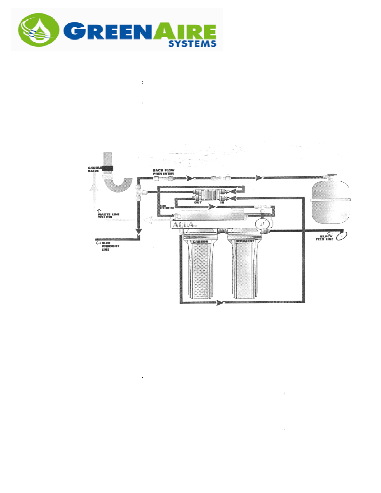
WATER PURIFICATION
SUPPLY SIDE TYPICAL INSTALLATION
1)Componentsoutlinedindashed linesinadditiontoPanelandDTAprovidedbyReensAir,
TYPICAL UNIT
WATER PURIFICATION
SCALE: 1"=24"
BY: DJR -12/11/08
ISSUE:01 REV: 00
SIDEVIEW
ofcondensate
InstallDTAatslight
anglefordrainback
PANEL
WIREBACK
TOCONTROL
SWITCH
AIRFLOW
SUPPLYAIR
3"ODCOPPER
4"OD
METAL
SHEET
9"
Tube
Assembly
Dispersion
el/Generator
iredbackto
tronicWall
Elec
sensorw
ControlPan
R
0
O
0
T
0
A
1
R
H
E
A
N
R
E
G
completelyopen
InstallGeneratorat
TO
REDUCE
3"ATPANEL
FAN
angleso doorcanswing
HX
FILTER
INTAKE
R
ROMCLOSETDOO
t
FRONTVIEWF
TANK
STATION
STORAGE
isfornotifiationonly.
necessarillyhere. This
Note:water stationlocationis no
NOTES:
all otherpiping,wiring,mounting andinstallationbyothers.
2)Controllingwall mountedsensor,airflowswitch, providedbyReensAir.
3)Donot trapsupplypipingtoDTA- mustdrainbacktoPanel.
7

15AmpCir.
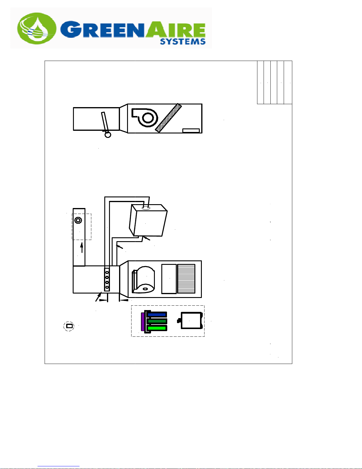
RETURN AIR SIDE INSTALLATION
2)Controllingsensor, air flowswitchprovidedbyReensAir.
15AmpCir.
NTS
2)Controllingsensor, air flowswitchprovidedbyReensAir.
1000SERIES
FIGURE 1: TYPICAL LAYOUT
COLD
WATER
BY: D.J.REENS
TODRAIN
STATION
WATER PURIFICATION
FIGURE 1: TYPICALLAYOUT
CONTROL PANEL
1/4" LINETOADDITIONAL
PANEL
120V
OUTLET
3"PVC
DUCT MTD. SENSOR (4 WIRE)
AIRFLOW SWITCH
SUPPLYAIR
20"x20"x12"
REENSAIR
CONTROL
3"L-1/2" pipe
nippleminimum.
DRAINALLLOWPOINTS
10"
TANK
STORAGE
DUCT
RETURN
ELECTRONIC
AIRFILTER
NOTES:
1)Components outlinedin dashed circles providedbyReensAir,
allother piping, wiring, mountingandinstallationbyothers.
3)Allattic spacehumidifierlocationsmustbeheatedandfreezeprotected.
4)Alllowpointsofdistributiontubingmustbedrained.
5)Pleasereviewall ProjectdocumentationandIO&Ms formoreinformation.
8

STORAGE
STORAGE
0
06/14/13
Rev.
Date
GREENAIRESYSTEMS,LLC
270D ROWEAVE.
MILFORD, CT06460
(203)683-1644
Room
Res.
Greer
Project
HL
AFS
FOGON
38
40
J K
H
I
SETPT.
RETURN
CONTROLLER
ON/OFF
14"H x 12"Wx 7"D
RAH-1030/1050-STS
Product
VisitGreenAireat www.greenairesystems.com
AIR
SUPPLY
cable
RHC
CC
lowvoltage
multi-conductor
HorizontalAC Unit
FILTER
andhorizontal tubes
DTA-Vertical header
'P'Trap
G
Duct extension
16"LSheet Metal
F
C
RETURN SIDEAPPLICATION
TANK
3 GAL.
:
1050-STSUNIT
20"Lx12"Wx10"H
3/8"OD
waterdrain
E
Humidity Sensor, duct orroommounted.
Air FlowSwitch
SupplyHi-Limit Switch
Humidifiers
3/8" Main to
D
3/8" Main
1/4"OD
C
ROFeed
ADDITIONAL ITEMS
HL
STATION
AFS
ROWATER
B
A
9

1/4" OD
AFS
1/4" OD
SUPPLY SIDEAPPLICATION
* PleaseNote: One(1)ROWater Stationcanserve
SUPPLY SIDEAPPLICATION
* PleaseNote: One(1)ROWater Stationcanserve
HL
38
AIR
SUPPLY
40
HOUR
004550
SETPT.
RETURN
CONTROLLER
METER
HI J K
FOGON
ON/OFF
header and
DTA- vertical
horizontaltubes
'P'Trap
16"Hx 12"Wx7"D
RAH-1090-STS
F
G
cable
1/4"OD
ROFeed
1050-STSUNIT
20"Lx12"Wx10"H
waterdrain
lowvoltage
multi-conductor
E
D
3/8" Main
C
RHC
CC
:
HorizontalACUnit
FILTER
AirFlowSwitch
SupplyHi-Limit Switch
HumiditySensor, ductor roommounted.
ADDITIONALITEMS
HL
AFS
C
TANK
3 GAL.
STORAGE
Humidifiers
3/8" Mainto
STATION
ROWATER
B
ROStation is not uncommon.
multiplehumidifiers. Uptofive(5)humidifiers per
A
10

DUCT
DUCT
DTA
POSSIBLE LOCATIONS
STS UNIT
AIR
FEED
SUPPLY
SUPPLYDUCT
DTA
STSUNIT
AIR
FEED
SUPPLY
PLANVIEW
ACUNIT
STS UNIT
DTA
EXT.
STS UNIT
STS UNIT
STS UNIT
11

STS WIRING with CONTROLLER
- DENOTES ITEMLOCATION OUTSIDEOFCONTROL PANEL/GENERATOR.
On/Off
7
2
500VA
FLOATSWITCH
10
10
1
3
L1
120V/1PH
Circuit
Breaker
7.5Amp
+
CONTROLLER
CRC
120VAC
48VAC
3
N
2
RH
SENSOR
-
Power On
R
12
12A
12C
13
11
11
3
9
CRC
WETSWITCH
AFSSWITCH
HILIMIT
TIMER
RELAY
HHLS FLS
10Amp
Fuse
16
5
120VAC
24VAC
9
CR3
12B
CR3
SAFETY
17
10
1813
50VA
LLS
7
STS
BOX
6
CR4
WET
SWITCH
LowWater
17B
A
CR1
WS
R
TIMER
RELAY
CR5
Drain
SV-1
NO
CR4
15
21
FogOn
G
CR3
CR2
2
CR2
FCR
CR2
REMOTE START/STOPRELAY
CR-1
24 25
NOTES:
Fill
19
SV-2
NC
WiringDiagram
w/Controller
STS1090,70,50,30
Issue:01Rev:00
Date: 09/18/13
Scale:1"-3"
12

STS WIRING for REMOTE CONTROL
- DENOTESITEMLOCATIONOUTSIDE OFCONTROL PANEL/GENERATOR.
On/Off
120VAC
10
FLOAT SWITCH
18
10
1
11
11
12
L1
3
3
9
120V/1PH
Circuit
Breaker
7.5Amp
CR1
WETSWITCH
10Amp
Fuse
120VAC
48VAC
3
24VAC
9
REMOTESTART/STOP
24 25
500VA
7
5
2
40VA
CR3
12B
CR1
CR4
HI
LIMIT
Power On
7
6
LowWater
17B
R
STS
BOX
WET
SWITCH
A
WS
N
2
2
CR5
R
NOTES:
12A
12C
AFSSWITCH
HILIMIT
TIMER
RELAY
13
17
CR3
SAFETY
13
HHLS FLS
16
FCR
CR2
LLS
CR2
Drain
SV-1
NO
CR4
15
21
19
TIMER
RELAY
FogOn
G
Hour Meter
1111
CR2
Fill
SV-2
NC
CR3
10
Remote Control
Wiring
STS1090,70,50,30
Issue: 02Rev:01
Date: 10/11/13
Scale:1"-3"
13

STANDARD RAH WIRING WITH CONTROLLER
- DENOTESITEM LOCATION OUTSIDEOFCONTROLPANEL/GENERATOR.
On/Off
2
500 VA
50VA
FLOAT SWITCH
2
10
10
1
3
L1
120V/1PH
Circuit
Breaker
7.5Amp
+
CONTROLLER
CRC
120VAC
48VAC
3
N
RH
SENSOR
-
Power On
R
12
12A
12C
13
11
11
3
9
CRC
WET SWITCH
AFSSWITCH
HILIMIT
TIMER
RELAY
10Amp
Fuse
120VAC
24VAC
9
HHLS FLS
16
5
CR3
12B
CR3
SAFETY
7
7
UPC
TANK
6
CR4
10
WET
SWITCH
LowWater
17B
A
CR1
WS
R
TIMER
RELAY
Drain
SV-1
NO
FogOn
G
CR4
17
15
LLS
1813
21
Hour Meter
1111
CR3
CR2
2
CR2
FCR
CR2
FAN ONRELAY
CR-1
24 25
NOTES:
Fill
19
SV-2
NC
WiringDiagram
w/Controller
1090,70,50,30
Issue:01Rev:00
Date:10/5/13
Scale:1"-3"
14

TROUBLE SHOOTING SECTION
1.
No Power or Lites When Unit is turned on
breaker in the wiring circuitry. Make sure the breaker is turned on and there are fuses
located at each of the transformers in the Control Panel.
Power is on but no fog is produced:
Verify that the water valves are open.
Verify that the digital controller
lite value (target humidity set point) than the red, process value lite (actual
humidity level being read by the sensor). If the red value is above your target
required humidity levels have been satisfied and there is no need for
the humidifier to operate. To verify that the system is properly working
temporarily raise the set point to a higher value and make sure that the
comes on.
he air flow switch has closed after properly sensing that air is
moving in the duct.
Check the Wet Switch and verify that the green LED on the switch is lit. If it is
red that means that moisture was sensed by the switch and there is a leak
be fixed.
Water is not filling into the Tank:
Verify that the RO System is on line, i.e. the water valve is open and the
water filter housings have filled up and the unit is draining water as it makes
Make sure the shut off valve on
then pressurize the system.
Verify that you have at least 30
do not then a small booster pump may be required to supply adequate
temperature of the incoming water supply. If it is real cold, near or
below 40F, then the RO s
filters and make sure they are not clogged and filled with dirt
and debris. It is not uncommon with ne
water initially as the domestic water supplies come on line. This dirt and
suspended solids can sometimes prematurely clog the filters. If this is the
case call the factory for replacement filters.
that the Unit is Humidifying:
Keep track of the Panel mounted controller readings to see if the humidity is
Open up the Control Panel and observe the tank and if you see a cloudy, wet
tank along with the gurgling noise of water then the uni
and an overall circuit
has a higher green
Verify that the HiLimit switch circuit is closed.
top of the water tank is open. This will fill and
35PSI of water pressure to work with. If you
not make sufficient water.
w construction sites to have very dirty
t is definitely making
2.
3.
a.
b.
then the
humidifier
c. Verify that t
d.
that must
a.
: There are fuses
, if the Humidifier has one,
b.
c.
d. Check the
e. Check the pre-
4. Verifying
a.
b.
RO Water.
-
pressure.
ystem may
rising.
15

If the tank is clear and you can see to the bottom of it then it is not
c.
For verifying the amount of moisture being produced measure the air
conditions before the DTA and then downstream of it. You should measure
oth a decrease in dry bulb temperature and an increase in relative humidity.
Plot these on a Psychometric chart or call the Factory for further interpolation.
Low Humidity conditions continue to persist
Moisture migrates very quickly. Make su
humidified zone are closed or not opened long. Make sure no new or un
seen sources of outside air have been introduced to the space being
humidified as this will increase the load on the humidifier.
blower fan is turning on when there is a call for humidification
and not just when there is a call for heat. There is a dry contact relay in the
panel for exactly this purpose. Contact the Installer to verify that he utilized
this relay and that the cont
has been set up to run the fan only when there is a call for humidification.
Also make sure that the necessary zone dampers are also opening to allow
moisture to be delivered to the appropriate spaces.
ake sure the air filters to the furnace/blower/heat pump are not completely
clogged and restricting air flow.
Verify that the amperage draw for the 120VAC and 48VAC side of the circuits
at or near the rated amount for that system. If it is below the labeled
ratings then some of the UPC
fill solenoid valve is going on and off too frequently as well as the
Check water supply
Open the tank a
Verify that the RO System has had ample time to charge the system (this can
eral hours depending on the quantity and dis
supply piping to the humidifiers.
Ensure that there is enough
that feeds the RO System. A minimum of 35 PSI is required.
re all windows and doors to the
rol sequence on the blower system or heat pump
circuits are not functioning. Call the Factory if
situation happens when there is not enough water
will be very slow.
tance of pipe in the RO
pressure in the domestic water supply
fog.
working.
b
5.
a.
fore
b. Verify that the
c. M
d.
are
this is the case.
6. Unit is Cycling – the
‘Fog On’ lite.
a.
to fill the tank.
b.
take sev
:
-
– this
nd observe the rate of fill – it
c.
‘house’
16

PREVENTATIVE MAINTENANCE:
I. Humidifier Control Panel:
at the end or beginning of the season
the inside of the tank with a clean and non
down each of the discs as well. To take the tank lid off disconnect the supply
(and inlet supply if the unit is a supply side unit) then loosen
all the wing nuts and disconnect the fan wires at either the terminal or at the
Total time estimated:
1. verify the output is adequate by observ
making sure all the UPC discs that should be running are indeed doing so.
You may do this by observing the operation with a flash light and peering
through the plastic lid or taking the lid off (see above instructions) and
the unit on briefly (for 3
NOT EVER JUMP OUT THE LOW WATER FLOAT SWITCHES.
2. remember that the 1000 series
To determine whether how many are on line for
how many pairs of #6 and #7 wires are attached to the terminal switch. You
may have one or two spare banks (each bank has a capacity of
approximately 3 lbs/hr of gross fog production) depending on the required
unit. If you observe any non
add one of the spare banks by attaching their #6 & #7 lines to the terminals.
3. replace the float switch tank. Call the Factory for a replacement.
Replace the filters and the membrane on the RO Plant.
Total time estimated:
take the tank lid off and wipe down
abrasive rag. Make sure to wipe
ing the unit under operation and
5 seconds) WATER MUST BE IN THE TANK
output levels possible.
your particular unit
performing UPCs then you may
A) Every 2 – 3 years:
1.
pipe coupling
fan.
B) Every 5 years:
30 Minutes
–
-
turning
– DO
can have multiple
simply see
load for your
II. RO System:
A) Annually:
1.
-
15 minutes
17

DIGITAL CONTROLLER
18

19

Controller
Configuration
I) Initial Programming:
their controllers pre
is somehow lost, here is the access and settings:
A. To Access the “Initial Setting Mode” press
button for 3 seconds.
(this sets the input type, which is 0
(this sets the high of the process, RH)
(this sets the low of the process, RH)
(this sets the control type your using)
(control mode, use
(this feature not used)
(this feature not used)
(this feature not used)
(this feature not used)
(this feature not used)
(baud rate if data transfer was used)
(this feature not
Parity
Stop bit setting
humidifiers have
programmed in the Factory but if it
Here are the settings as shown
page 13:
:
All ReenAir
-
on
inPT = u10
tP-H = 100
tP-L = 0
Ctrl = on/off
S-HC= heat
ALA1= 0
SALA= off
CoSH= off
C-SL= ASCII
C-no = 1
bPS = 9600
LEN = 7
Prty = even
Stop = 1
-10v)
heat)
used)
20

21

2.4 MHz Nebulizer Board
Model#579R3 304SS with welds, stand brackets, top flange w/ PEMS and bottom hole
Polypropylene Float Switch
Way NC Stainless Stl Sol.Valve
Way NO Stainless Stl. Sol.Valve
Wall Metal Enclosure (20x20x12)
Terminal connector blocks
Terminal Connector End Blocks
120VAC to 48VAC Transformer. Rated
120VAC to 24VAC Transformer. Rated for 250VA. Open.
2 channels
-
Control Panel for the RAH 2000 & 3000
Relay 24VAC, 15 Amp, Dpdt, 8 terminal
8 terminal
Lexan Clear Poly Sheet .22"thk, 24"x24" sheet
PLC Controller for Humidity
Duct HMD50U
Wall HMW50U
Humidity Switch / simple controller
Duct 10
Nema 1 Control Panel 12x12z6
Gen Purpose Relay 24VAC 10Amp
8 SS Pan Head Phillips Machine Screw 8
8 SS Machine Screw Hex Nut. 8
EPDM Rubber cushioning and sealing washer #8 screw size, .150 ID, 5/16 OD, .062 thick, ...
8 Pan Head Phillips Machine Screw 8
12" x 24" x 1/4"
EPDM O Ring size: 4.5" OD
24VAC
red 120V
6 Amp 120V
Idec Double Pole Relay
Idec Double Pole Socket
-
Idec Single Pole Socket
PARTS LIST
32 Trhread, 1/2" Length, Pack of 100
Sales
Part No.
6001
6002
6003 Gasket for UPC Tank 6004
6005 26006 26007
6008
6009
6010 Jumpers - 2 Pole
6011
6012
6013 Hobo Data Logger
6014 Hobo Data Logger 6015 50 GPD RO System
6016 Redington Hour Meter
6017
6019 1.65 MHz PC Board
6020
6021 Relay Socket 6024
6025
6026 Humidity Sensor 6027 Humidity Sensor 6028
6029 Humidity Sensor 6030
6031
6032 Screw 186033 Nut 186034 Washer 6035 Screw 186036 Nat.Rubber Sheet 6037
6038 15 Amp Littlefuse
6039 Idec Pilot Lite - Red 6040 Switch - 2 pos., lited 6041 Circuit Breaker 6043 Idec Pilot Lite - Green 6045
6046
6047 Idec Single Pole Relay
6048
UPC Tank w/PE...
Item Description
Model#:579R3
for 500VA. Open.
24V
-35VDC input required. 0 - 10 VDC output.
-
-32, 5/16 width 100 per pack
-32, 3/4" long, 100 per pack
24VAC
- 24V
24VAC
Price
31.00
144.00
10.00
28.52
35.60
66.36
332.00
0.94
1.40
0.64
89.00
64.80
250.00
240.00
258.00
54.52
1,350.00
27.28
16.26
11.24
69.44
160.00
250.00
270.00
80.00
148.00
170.00
32.00
0.00
0.00
0.00
0.00
0.00
25.00
19.75
25.00
52.00
36.00
25.00
13.40
8.46
12.60
7.00
22

6050 EMI/RFI Fan Guard
Plastic Fan Guard for 4.69" Fan
Bulkhead Conn. 1/4T x 1/8MPT Brass Part#: B
clear w/ paper back in square ft units
10 Amp fuse, 12/32" dia. time delay, 250 VAC,
Amp Fuse, 13/32" dia., 250VAC time delay type
Little Giant Condensate pump. 120HP, 1/50 HP, 1.1 amps, 40 GPH at 8' head
Miniature Pressure Switch. Sensitive to .5" H2O <. Quick connect electrical connections. SPST...
All above prices are subject to change. Please call Factory or Factory
Representative for current pricing.
6051
6052
6053 .5" Acryllic Sheet 6055
6056 5
6057
6058
6124 Timer On/Off Relay
PLEASE NOTE:
1)
-400-11-2
10.00
2.00
9.00
22.00
7.00
7.00
75.00
55.00
146.00
23
 Loading...