


GREE ELECTRIC APPLIANCES,INC.OF ZHUHAI
Change for Life
Service Manual
GWH12TB-S3DBA1E
GWH12TB-S3DBA2E
GWH12TB-S3DBA3E
(Refrigerant R410A)
Models:

Service Manual
Table of Contents
Table of Contents
Part
Ⅰ
: Technical Information
.......................................................................1
1. Summary
......................................................................................................................1
2. Specications
..........................................................................................................2
2.1 Specication Sheet ...........................................................................................................2
2.2 Operation Characteristic Curve ........................................................................................4
2.3 Capacity Variation Ratio According to Temperature .........................................................4
2.4 Noise Curve ......................................................................................................................5
2.5 Cooling and Heating Data Sheet in Rated Frequency .....................................................5
3. Outline Dimension Diagram
........................................................................6
3.1 Indoor Unit ........................................................................................................................6
3.2 Outdoor Unit .....................................................................................................................7
4. Refrigerant System Diagram
......................................................................8
5. Electrical Part
...........................................................................................................9
5.1 Wiring Diagram .................................................................................................................9
5.2 PCB Printed Diagram ..................................................................................................... 11
6. Function and Control
......................................................................................13
6.1 Remote Controller Introduction .....................................................................................13
6.2 Operation of Smart Control (Smart Phone, Tablet PC) For Gree ...................................19
6.3 Operation of Smart Control (Smart Phone, Tablet PC) .................................................32
6.4 Brief Description of Modes and Functions ......................................................................45
Part
Ⅱ
: Installation and Maintenance
.................................................53
7. Notes for Installation and Maintenance
..........................................53
8. Installation
................................................................................................................56
8.1 Installation Dimension Diagram ......................................................................................56
8.2 Installation Parts-checking ............................................................................................58
8.3 Selection of Installation Location ....................................................................................58
8.4 Electric Connection Requirement ...................................................................................58
8.5 Installation of Indoor Unit ................................................................................................58
8.6 Installation of Outdoor Unit .............................................................................................61
8.7 Vacuum Pumping and Leak Detection ...........................................................................62
8.8 Check after Installation and Test Operation ...................................................................62

Service Manual
Table of Contents
9. Maintenance
............................................................................................................63
9.1 Troubleshooting for Normal Malfunction .........................................................................63
9.2 Error Code List ...............................................................................................................67
9.3 Troubleshooting for Main Malfunction ............................................................................72
10. Exploded View and Parts List
..............................................................85
10.1 Indoor Unit ....................................................................................................................85
10.2 Outdoor Unit .................................................................................................................88
11. Removal Procedure
.......................................................................................90
11.1 Removal Procedure of Indoor Unit ...............................................................................90
11.2 Removal Procedure of Outdoor Unit ............................................................................97
Appendix:
......................................................................................................................102
Appendix 1: Reference Sheet of Celsius and Fahrenheit ..................................................102
Appendix 2: Conguration of Connection Pipe ...................................................................102
Appendix 3: Pipe Expanding Method .................................................................................103
Appendix 4: List of Resistance for Temperature Sensor ....................................................104

1
Service Manual
Technical Information
Part
Ⅰ
: Technical Information
1. Summary
Indoor Unit:
Remote Controller:
YAC1FB
GWH12TB-S3DBA3E/I
GWH12TB-S3DBA1E/I
GWH12TB-S3DBA2E/I
Outdoor Unit:
GWH12TB-S3DBA3E/O
MODE FAN
TURBO
SLEEPI FEEL
TIMER ON
TIMER OFF
CLOCK
QUIET
X-FAN TEMP LIGHT

2
Service Manual
Technical Information
Parameter Unit Value
Model
1.GWH12TB-S3DBA1E
2.GWH12TB-S3DBA2E
3.GWH12TB-S3DBA3E
Product Code
1.CB148009102 2.CB411003901
3.CB412002902 CB412002903
Power
Supply
Rated Voltage V~ 220-240
Rated Frequency Hz 50/60
Phases 1
Power Supply Mode Outdoor
Cooling Capacity(Min~Max) W 3500(1150~4000)
Heating Capacity(Min~Max) W 3650(2000-5300)
Cooling Power Input(Min~Max) W 890(215~1300)
Heating Power Input(Min~Max) W 900(390~1900)
Cooling Current Input A 4.00
Heating Current Input A 4.00
Rated Input W 1900
Rated Current A 8.50
Air Flow Volume (SH/H/MH/M/ML/L/SL) m3/h 740/670/610/530/460/410/380
Dehumidifying Volume L/h 1.40
AEER 3.93
ACOP 4.06
SEER 7.80
SCOP
Average:4.6
Warmer:5.6
Colder:3.2
Application Area m
2
16-24
Indoor Unit
Indoor Unit Model
1.GWH12TB-S3DBA1E/I
2.GWH12TB-S3DBA2E/I
3.GWH12TB-S3DBA3E/I
Indoor Unit Product Code
1.CB148N09102 2.CB411N03900
3.CB412N02902 CB412N02903
Indoor Unit Fan Type Cross-ow
Indoor Unit Fan Diameter Length(DXL) mm Φ98X662
Cooling Speed (SH/H/MH/M/ML/L/SL) r/min 1350/1070/1000/900/800/700/500
Heating Speed (SH/H/MH/M/ML/L/SL) r/min 1350/1150/1080/1030/980/900/850
Indoor Unit Fan Motor Power Output W 15
Indoor Unit Fan Motor RLA A 0.07
Indoor Unit Fan Motor Capacitor μF /
Evaporator Form Aluminum Fin-copper Tube
Evaporator Pipe Diameter mm Φ7
Evaporator Row-n Gap mm 2-1.5
Evaporator Coil Length (LXDXW) mm 662X25.4X305
Swing Motor Model MP24HA/MP24HB/MP24HC
Swing Motor Power Output W 2.4/2.4/2.4
Fuse Current A 3.15
Sound Pressure Level (SH/H/MH/M/
ML/L/SL)
dB (A) 45/36/34/32/28/24/22
Sound Power Level (SH/H/MH/M/ML/
L/SL)
dB (A) 59/50/48/46/42/38/35
Dimension (WXHXD) mm 866X292X209
Dimension of Carton Box (LXWXH) mm 942X374X282
Dimension of Package (LXWXH) mm 945X377X297
Net Weight kg 11
Gross Weight kg 13
2. Specications
2.1 Specication Sheet

3
Service Manual
Technical Information
Outdoor Unit
Outdoor Unit Model GWH12TB-S3DBA3E/O
Outdoor Unit Product Code CB412W02901
Compressor Manufacturer ZHUHAI LANDA COMPRESSOR CO., LTD
Compressor Model QXAT-B096zE070
Compressor Oil 68EP
Compressor Type Rotary
Compressor Locked Rotor Amp (L.R.A) A 40.00
Compressor Rated Load Amp (RLA) A 5.40
Compressor Power Input W 1130
Compressor Overload Protector 1NT11L-6233
Throttling Method Electron expansion valve
Set Temperature Range °C 16~30
Cooling Operation Ambient
Temperature Range
°C -15~54
Heating Operation Ambient
Temperature Range
°C -30~24
Condenser Form Aluminum Fin-copper Tube
Condenser Pipe Diameter mm Φ7
Condenser Rows-n Gap mm 2.5-1.4
Condenser Coil Length (LXDXW) mm 773X57X550
Outdoor Unit Fan Motor Speed rpm 850/700/600
Outdoor Unit Fan Motor Power Output W 30
Outdoor Unit Fan Motor RLA A 0.15
Outdoor Unit Fan Motor Capacitor μF /
Outdoor Unit Air Flow Volume m3/h 2000
Outdoor Unit Fan Type Axial-ow
Outdoor Unit Fan Diameter mm Φ438
Defrosting Method Automatic Defrosting
Climate Type T1
Isolation I
Moisture Protection IP24
Permissible Excessive Operating
Pressure for the Discharge Side
MPa 4.3
Permissible Excessive Operating
Pressure for the Suction Side
MPa 2.5
Sound Pressure Level (H/M/L) dB (A) 55/-/-
Sound Power Level (H/M/L) dB (A) 62/-/-
Dimension (WXHXD) mm 899X596X378
Dimension of Carton Box (LXWXH) mm 945X417X630
Dimension of Package (LXWXH) mm 948X420X645
Net Weight kg 43.5
Gross Weight kg 46.5
Refrigerant R410A
Refrigerant Charge kg 1.3
Connection
Pipe
Connection Pipe Length m 5
Connection Pipe Gas Additional
Charge
g/m 20
Outer Diameter of Liquid Pipe mm Φ6
Outer Diameter of Gas Pipe mm Φ12
Max Distance Height m 10
Max Distance Length m 20
Note: The connection pipe applies metric diameter.
The above data is subject to change without notice; please refer to the nameplate of the unit.

4
Service Manual
Technical Information
Cooling
0
2
4
6
8
10
1502030405
05
060 70 80 90 15020304060708
090
Compressor speed (rps)
Current (A)
Heating
0
2
4
6
8
10
Compressor speed (rps)
Current (A)
Condition
Indoor:DB27°C WB19°C
Outdoor:DB35°C WB24°C
Indoor air flow: Super High
Pipe length: 5m
Condition
Indoor:DB20°C
Outdoor:DB7°C
Indoor air flow:Super High
Pipe length: 5m
12K
12K
2.2 Operation Characteristic Curve
2.3 Capacity Variation Ratio According to Temperature
Cooling Heating
-30-1532 35 38 42 48
60
70
80
90
100
110
120
50
40
40
50
120
110
100
90
80
70
60
10
70-8-20
Outdoor Temp.(°C) Outdoor Temp.(°C)
• Conditions
Indoor: DB27°C/WB19°C
Outdoor: DB35°C/WB24°C
Indoor air flow: High
Pipe length: 5m
• Conditions
Indoor: DB20°C/WB15°C
Outdoor: DB7°C/WB6°C
Indoor air flow: High
Pipe length: 5m
Capacity ratio(%)
Capacity ratio(%)

5
Service Manual
Technical Information
2.5 Cooling and Heating Data Sheet in Rated Frequency
Cooling:
Rated cooling
condition(°C) (DB/WB)
Model
Pressure of gas pipe
connecting indoor and
outdoor unit
Inlet and outlet pipe
temperature of heat
exchanger
Fan speed of
indoor unit
Fan speed of
outdoor unit
Compressor
revolution
(rps)
Indoor Outdoor P (MPa) T1 (°C) T2 (°C)
27/19 35/- 12K 0.9 ~ 1.2 12 to 14 39 to 43 TURBO High 54
Instruction:
T1: Inlet and outlet pipe temperature of evaporator
T2: Inlet and outlet pipe temperature of condenser
P: Pressure at the side of big valve
Connection pipe length: 5 m.
Heating:
Rated heating
condition(°C) (DB/WB)
Model
Pressure of gas pipe
connecting indoor and
outdoor unit
Inlet and outlet pipe
temperature of heat
exchanger
Fan speed of
indoor unit
Fan speed of
outdoor unit
Compressor
revolution
(rps)
Indoor Outdoor P (MPa) T1 (°C) T2 (°C)
20/15 7/6 12K 2.1 ~ 2.6 34 to 37 3 to 5 TURBO High 56
2.4 Noise Curve
20
25
30
35
40
45
Super
High
Indoor fan motor rotating speed (rps)
Indoor Unit Outdoor Unit
Noise/dB(A)
12K
30
35
40
45
50
55
Compressor speed (rps)
Noise/dB(A)
High Middle
High
Middle Middle
Low
Low Quiet
0820 30 40 50 60 70 80
90
12K

6
Service Manual
Technical Information
3. Outline Dimension Diagram
3.1 Indoor Unit
Unit:mm
Model W H D Q R S W1 W2
12K 866 292 209 162 541 163 160 80
WD
H
QRS
Φ55Φ55
35
W2W1

7
Service Manual
Technical Information
3.2 Outdoor Unit
Unit:mm
596
354
899
303 838
378
550

8
Service Manual
Technical Information
4. Refrigerant System Diagram
Connection pipe specication:
Liquid : 1/4" (6 mm)
Gas :1/2" (12mm)
INDOOR UNIT OUTDOOR UNIT
HEAT
EXCHANGE
(EVAPORATOR)
HEAT
EXCHANGE
(CONDENSER)
COMPRESSOR
GAS SIDE
3-WAY VALVE
LIQUID SIDE
2-WAY VALVE
COOLING
HEATING
Accumlator
Discharge
Suction
4-Way valve
Electron
Strainer
Strainer
expansion
valve
Strainer
Capillary
D
Strainer
Intercooler

9
Service Manual
Technical Information
5. Electrical Part
5.1 Wiring Diagram
● Indoor Unit
●Instruction
Symbol Symbol Color Symbol Symbol Color Symbol Name
WH White GN Green CAP Jumper cap
YE Yellow BN Brown COMP Compressor
RD Red BU Blue Grounding wire
YEGN Yellow/Green BK Black / /
VT Violet OG Orange / /
Note: Jumper cap is used to determine fan speed and the swing angle of horizontal lover for this model.
3OHDVHGRQWWRXFKDQ\
HOHFWURQLFFRPSRQHQWRU
WHUPLQDOZKHQWKHPDFKLQH
LVUXQQLQJVWRSSLQJRU
KDVEHHQSRZHUHGRIIIRU
OHVVWKDQPLQXWHVWR
SUHYHQWHOHFWULFVKRFN
:$51,1*
(/(&75267$7,&
'('867,1*
;
<(*1
+($/7+/
+($/7+1
%8
5'
*(1(5$725
3/$60$
$1'
%2$5'
7(03
7(03
',63
$3
',63
',63/$<
5(&(,9(5
)$102725
'&02725
78%(
5220
6(1625
6(1625
78%(
57
57
5220
$3
6$
6:,7&+
&211(&725
12
;
&
;
%.
:+
&/($1
0
0
83'2:1
02725
67(33,1*
02725
67(33,1*
02725
83'2:1
/()75,*+7
6:,1*8'
6:,1*8'
67(33,1*
35,17('&,5&8,7%2$5'
-803
&$3
6:,1*/5
0
<(*1
<(*1
%8
%.
%1
287'22581,7
%/2&.
&11(&7,1*
&$%/(
7(50,1$/
1
;7
(9$325$725
3(
%8
%.
%1
1
&20287
$&/
3(
&2/'
&20,11(5
;
$3
:,5('
&21752//(5
0
:,),
:,),02'8/(
237,21$/
;
GWH12TB-S3DBA3E/I(CB412N02902)
6361268408

10
Service Manual
Technical Information
● Outdoor Unit
These wiring diagrams are subject to change without notice; please refer to the one supplied with the unit.
GWH12TB-S3DBA3E/O
GWH12TB-S3DBA1E/I GWH12TB-S3DBA2E/I GWH12TB-S3DBA3E/I(CB412N02903)
/1
(;3$16,21
9$/9(
(/(&7521,&
5($&725
9$/9(
:$<
6:,7&+
35(6685(
3527(&72529(5/2$'
9$/9(
:$<
2)$1VA
AC-L2
<9
6$7
/
/
/;
/
2*
:+
/;
&203:&2039
+33
29&&203
///
)$1
&203
3(
&1
(.9
&208
$&/
:$<
$&/
1
5'
8%(<
<(*1
5'
&2038
3(
V
W
U
(
2)$1
57
57 57
0
&203
<9
N2
N3
BU
%1
%.
%8
/
<(*1
/
3(
0$*1(7,&
5,1*
1
%/2&.
7(50,1$/
;7
/
N
<(*1
,1'22581,7
32:(5
3(
%8
%.
%1
<(*1
%8
%1%.
<(*1
RIHOHFWULFVKRFN
3OHDVHGRQWWRXFKDQ\
WHUPLQDOZKHQWKHPDFKLQHLV
UXQQLQJVWRSSLQJRUKDVEHHQ
SRZHUHGRIIIRUOHVVWKDQ
PLQXWHVWRSUHYHQWWKHULVN
/
0RWRU
DSSOLHVWRWKH
LURQVKHOOPRWRU
JURXQGRQO\
78%(
7(03
6(1625
5220
7(03
6(1625
(;+$867
7(03
6(1625
+($7/
+($71
%27720
%$1'
+($71
&2035(6625
%$1'+($7(5
02725
:+ :+
K
K K
+($7(5
97 97
5'
BU BU
&1
E
<(*1
&1
$30DLQ%RDUG
:$51,1*
3
127(
63610000231
600007000019
3OHDVHGRQWWRXFKDQ\
HOHFWURQLFFRPSRQHQWRU
WHUPLQDOZKHQWKHPDFKLQH
LVUXQQLQJVWRSSLQJRU
KDVEHHQSRZHUHGRIIIRU
OHVVWKDQPLQXWHVWR
SUHYHQWHOHFWULFVKRFN
/
/
/
:$51,1*
(/(&75267$7,&
'('867,1*
;
<(*1
+($/7+/
+($/7+1
%8
5'
*(1(5$725
3/$60$
$1'
%2$5'
7(03
7(03
',63
$3
',63
',63/$<
5(&(,9(5
)$102725
'&02725
78%(
5220
6(1625
78%(
57
57
5220
$3
6$
6:,7&+
&211(&725
12
;
&
;
%.
:+
&/($1
0
0
83'2:1
02725
67(33,1*
02725
67(33,1*
02725
83'2:1
/()75,*+7
6:,1*8'
6:,1*8'
67(33,1*
35,17('&,5&8,7%2$5'
-803
&$3
6:,1*/5
0
<(*1
<(*1
%8
%.
%1
287'22581,7
%/2&.
&11(&7,1*
&$%/(
7(50,1$/
1
;7
(9$325$725
3(
%8
%.
1
&20287
$&/
3(
&2/'
&20,11(5
;
$3
:,5('
&21752//(5
0
:,),
:,),02'8/(
237,21$/
;
%1
11
Service Manual
Technical Information
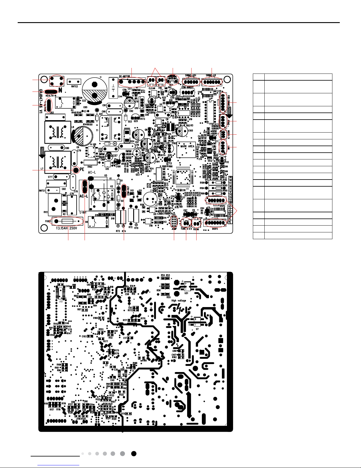
5.2 PCB Printed Diagram
Indoor unit
● Top view
● Bottom view
1
2
3
4
5 6 7 8 9
10
11
12
13
14
151617181920
1 Grounding wire
2
Interface of health function
live wire
3
Interface of health function
neutral wire
4 Neutral wire
5 Interface of DC motor
6
Interface of electrostatuc
dedusting
7 Auto button
8 Up&down swing interface 1
9 eft&right swing interface
10 Up&down swing interface 2
11 Interface of DRED
12 Interface of IC-DOOR
13 Interface of WiFi
14 Display interface
15
Interface of ambient
temperature sensor
16
Interface of tube temperature
sensor
17 Jumper cap
18 Communication interface
19 Live wire interface
20 Fuse

12
Service Manual
Technical Information
Outdoor unit
● Top view
● Bottom view
2
1
3
4
5
6
8
7
9
10
11
12
13
14 15

13
Service Manual
Technical Information
Introduction for icons on display screen
Introduction for buttons on remote controller
Note:
● This is a general use remote controller, it could be used for the air conditioners with multifunction; For some function, which the
model doesn't have, if press the corresponding button on the remote controller that the unit will keep the original running status.
● After putting through the power, the air conditioner will give out a sound. Operation indictor " " is ON (red indicator). After that,
you can operate the air conditioner by using remote controller.
●
Under on status, pressing the button on the remote controller, the signal icon " "
on the display of remote controller will blink once
and the air conditioner will give out a “de” sound, which means the signal has been sent to the air conditioner.
WIFI
6
3
7
9
11
13
15
12
14
16
10
8
5
4
2
1
1 ON/OFF button
2 MODE button
3 FAN button
4 TURBO button
6 button
7 button
9 I FEEL button
14 LIGHT button
15 button
16 TEMP button
11 CLOCK button
12
QUIET button(This function is unavailable for this
model)
13 X-FAN button(Note: X-FAN is the same with BLOW.)
10 TIMER ON / TIMER OFF button
8 SLEEP button
5
▲/ button
▲
WIFI
Send signal
Turbo mode
8℃ heating function
Set temperature
Set time
X-FAN function
TIMER ON /TIMER OFF
Child lock
Up & down swing
Left & right swing
Set fan speed
Light
Temp. display type
:Set temp.
:Outdoor ambient temp.
:Indoor ambient temp.
Sleep mode
Clock
Heat mode
Fan mode
Dry mode
Cool mode
Auto mode
Operation mode
I feel
Healthy mode
Scavenging functions
Quiet
WIFI(This is a general remote controller.Some models have this function while some
do not. Please refer to the actual models.)
6. Function and Control
6.1 Remote Controller Introduction

14
Service Manual
Technical Information
1. ON/OFF button
2. MODE button
3. FAN button
Press this button can turn on or turn off the air conditioner. After turning on the air conditioner, operation indicator " "on indoor unit’s
display is ON (green indicator. The colour is different for different models), and indoor unit will give out a sound.
● When selecting auto mode, air conditioner will operate automatically according to ex-factory setting. Set temperature can’t be adjusted and
will not be displayed as well. Press "FAN" button can adjust fan speed. Press " " / " " button can adjust fan blowing angle.
● After selecting cool mode, air conditioner will operate under cool mode. Cool indicator " "on indoor unit is ON. Press "▲" or " ▲ "
button to adjust set temperature. Press "FAN" button to adjust fan speed. Press " " / " " button to adjust fan blowing angle.
● When selecting dry mode, the air conditioner operates at low speed under dry mode. Dry indicator " " on indoor unit is ON. Under dry
mode, fan speed can’t be adjusted. Press " " / " " button to adjust fan blowing angle.
● When selecting fan mode, the air conditioner will only blow fan, no cooling and no heating. All indicators are OFF. Press "FAN" button to
adjust fan speed. Press " " / " " button to adjust fan blowing angle.
● When selecting heating mode, the air conditioner operates under heat mode. Heat indicator " " on indoor unit is ON. Press "▲" or " ▲
" button to adjust set temperature. Press "FAN" button to adjust fan speed. Press " " / " " button to adjust fan blowing angle. (Cooling
only unit won’t receive heating mode signal. If setting heat mode with remote controller, press ON/OFF button can’t start up the unit.
Note:
● For preventing cold air, after starting up heating mode, indoor unit will delay 1~5 minutes to blow air (actual delay time is depend on indoor
ambient temperature).
● Set temperature range from remote controller: 16~30℃(61-86°F); Fan speed: auto, low speed, medium speed, high speed.
4. TURBO button
Under COOL or HEAT mode, press this button to turn to quick COOL or quick HEAT mode. " " icon is displayed on remote controller.
Press this button again to exit turbo function and " " icon will disappear. If start this function, the unit will run at super-high fan speed to
cool or heat quickly so that the ambient temp. approachs the preset temp. as soon as possible.
5. ▲/▲ button
6. button
● Press " ▲ " or " ▲ " button once increase or decrease set temperature 1℃(°F). Holding " ▲ " or " ▲ " button, 2s later, set temperature
on remote controller will change quickly. On releasing button after setting is finished, temperature indicator on indoor unit will change
accordingly. (Temperature can’t be adjusted under auto mode)
● When setting TIMER ON, TIMER OFF or CLOCK, press " ▲ " or " ▲ " button to adjust time. (Refer to CLOCK, TIMER ON, TIMER OFF
buttons) When setting TIMER ON, TIMER OFF or CLOCK, press " ▲ " or " ▲ " button to adjust time. (Refer to CLOCK, TIMER ON, TIMER
OFF buttons)
Press this button can select left & right swing angle. Fan blow angle can be selected
circularly as below:
Note:
● Press this button continuously more than 2s, the main unit will swing back and forth from left to right, and then loosen the button, the unit
will stop swinging and present position of guide louver will be kept immediately.
This button is used for setting Fan Speed in the sequence that goes from AUTO , , , , to then back to Auto.
Press this button to select your required operation mode.
AUTO COOL FA N
DRY HEAT
no display
(stops at current position)
Auto
Medium spee
d
Low-Medium speedLow speed
High speedMedium-High speed

15
Service Manual
Technical Information
● Under swing left and right mode, when the status is switched from off to , if press this button again 2s later, status will switch to off
status directly; if press this button again within 2s, the change of swing status will also depend on the circulation sequence stated above.
7. button
8. SLEEP button
9. I FEEL button
10. TIMER ON / TIMER OFF button
Press this button can select up & down swing angle. Fan blow angle can be selected
circularly as below:
Press this button, can select Sleep 1 ( ), Sleep 2 ( ), Sleep 3 ( ) and cancel the Sleep, circulate between these, after electried,
Sleep Cancel is defaulted.
● Sleep 1 is Sleep mode 1, in Cool modes; sleep status after run for one hour, the main unit setting temperature will increase 1°C, two hours,
setting temperature increa sed 2°C, then the unit will run at this setting temperature; In Heat mode: sleep status after run for one hour, the
setting temperature will decrease 1°C, two hours, setting temperature will decrease 2°C, then the unit will run at this setting temperature.
● Sleep 2 is sleep mode 2, that is air conditioner will run according to the presetting agroup of sleep temperature curve.
● Sleep 3-the sleep curve setting under Sleep mode by DIY;
(1)Under Sleep 3 mode, press “Turbo” button for a long time, remote controller entersinto user individuation sleep setting status, at this time,
the time of remote controllerwill display “1hour”, the setting temperature “88” will display the corresponding temp-erature of last setting sleep
curve and blink (The rst entering will display according tothe initial curve setting value of original factory);
(2)Adjust “+” and “-” button, could change the corresponding setting temperature, afteradjusted, press “Turbo” button for conrmation;
(3)At this time, 1hour will be automatically increased at the timer postion on the remotecontrol, (that are "2hours" or "3hours" or "8hours"),
the place of setting temperature "88"will display the corresponding temperature of last setting sleep curve and blink;(4) Repeat the above
step (2)~(3) operation, until 8 hours temperature setting nished,sleep,curve setting nished, at this time, the remote controller will resume
the original timer display; temperature display will resume to original setting temperature.
● Sleep3- the sleep curve setting under Sleep mode by DIY could be inquired:The user could accord to sleep curve setting method to inquire
the presetting sleep curve, enter into user individuation sleep setting status, but do not change the tempera-ture, press “Turbo” button directly
for conrmation. Note: In the above presetting or enquiry procedure, if continuously within 10s, there is no button pressed, the sleep curve
setting within 10s, there is no button pressed, the sleep curve setting status will be automatically quit and resume to display the original
displaying. In the presetting orenquiry procedure, press "ON/OFF" button, "Mode" button, "Timer" button or "Sleep" button, the sleep curve
setting or enquiry status will quit similarly.
Press this button to start I FEEL function and " " will be displayed on the remote controller. After this function is set, the remote controller
will send the detected ambient temperature to the controller and the unit will automatically adjust the indoor temperature according to the
detected temperature. Press this button again to close I FEEL function and " " will disappear.
● Please put the remote controller near user when this function is set. Do not put the remote controller near the object of high temperature
or low temperature in order to avoid detecting inaccurate ambient temperature.
● TIMER ON button
"TIMER ON" button can set the time for timer on. After pressing this button, " " icon disappears and the word "ON" on remote controller
blinks. Press " ▲ " or " ▲ "button to adjust TIMER ON setting. After each pressing " ▲ " or " ▲ " button, TIMER ON setting will increase
or decrease 1min. Hold " ▲ " or " ▲ " button, 2s later, the time will change quickly until reaching your required time. Press "TIMER ON" to
conrm it. The word "ON" will stop blinking. " " icon resumes displaying. Cancel TIMER ON: Under the condition that TIMER ON is started
up, press "TIMER ON" button to cancel it.
● TIMER OFF button
● When selecting " ", air conditioner is blowing fan automatically. Horizontal louver will automatically swing up & down at maximum angle.
● When selecting " 、 、 、 、 ", air conditioner is blowing fan at xed position. Horizontal louver will stop at the xed position.
● When selecting " 、 、 " , air conditioner is blowing fan at xed angle. Horizontal louver will send air at the xed angle.
● Hold " "button above 2s to set your required swing angle. When reaching your required angle, release the button.
Note:
● " 、 、 " may not be available. When air conditioner receives this signal, the air conditioner will blow fan automatically.
● Press this button continuously more than 2s, the main unit will swing back and forth from up to down, and then loosen the button, the unit
will stop swinging and present position of guide louver will be kept immediately.
● Under swing up and down mode, when the status is switched from off to , if press this button again 2s later, status will switch to off
status directly; if press this button again within 2s,the change of swing status will also depend on the circulation sequence stated above.
no display
(horizontal louvers stops
at current position)

16
Service Manual
Technical Information
11. CLOCK button
Press this button to set clock time. " " icon on remote controller will blink. Press " ▲ " or " ▲ " button within 5s to set clock time. Each
pressing of " ▲ " or " ▲ " button, clock time will increase or decrease 1 minute. If hold " ▲ " or " ▲ " button, 2s later, time will change quickly.
Release this button when reaching your required time. Press "CLOCK" button to conrm the time. " " icon stops blinking.
Note:
● Clock time adopts 24-hour mode.
● The interval between two operation can’t exceeds 5s. Otherwise, remote controller will quit setting status. Operation for TIMER ON/TIMER
OFF is the same.
"TIMER OFF" button can set the time for timer off. After pressing this button," "icon disappears and the word "OFF" on remote controller
blinks. Press " ▲ " or " ▲ " button to adjust TIMER OFF setting. After each pressing " ▲ " or " ▲ " button, TIMER OFF setting will increase
or decrease 1min. Hold " ▲ " or " ▲ " button, 2s later, the time will change quickly until reaching your required time. Press "TIMER OFF"
word "OFF" will stop blinking. " " icon resumes displaying. Cancel TIMER OFF. Under the condition that TIMER OFF is started up, press
"TIMER OFF" button to cancel it.
Note:
● Under on and off status, you can set TIMER OFF or TIMER ON simultaneously.
● Before setting TIMER ON or TIMER OFF, please adjust the clock time.
● After starting up TIMER ON or TIMER OFF, set the constant circulating valid. After that, air conditioner will be turned on or turned off
according to setting time. ON/OFF button has no effect on setting. If you don’t need this function, please use remote controller to cancel it.
12. QUIET button
Press this button, the Quiet status is under the Auto Quiet mode (display " " and "AUTO" signal ) and Quiet mode (display " " singal)
and Quiet OFF (there is no signal of " " displayed), after powered on, the Quiet OFF is defaulted.
Note:
●
The Quiet function can be set up in all modes; Under the Quiet mode,the fan speed is not available.
● When quiet function is selected:
Under cooling mode: indoor fan operates at notch 4 speed. 10 minutes later or when indoor ambient temperature≤28°C, indoor fan will
operate at notch 2 speed or quiet mode according to the comparison between indoor ambinet temperature and set temperature.
Under heating mode: indoor fan operates at notch 3 speed or quiet mode according to the comparison between indoor ambient temperature
and set temperature.
Under dry, fan mode: indoor fan operates at quiet mode.
Under auto mode: the indoor fan operates at the auto quiet mode according to actual cooling, heating or fan mode.
● The Quiet function is only available for some models.
13. X-FAN button
Pressing this button in COOL or DRY mode, the icon " " is displayed and the indoor fan will continue operation for 2 minutes in order to
dry the indoor unit even though you have turned off the unit. After energization, X-FAN OFF is defaulted.X-FAN is not available in AUTO,
FAN or HEAT mode.
This function indicates that moisture on evaporator of indoor unit will be blowed after the unit is stopped to avoid mould.
● Having set X-FAN function on: After turning off the unit by pressing ON/OFF button indoor fan will continue running for about 2 min. at low
speed. In this period, press X-FAN button to stop indoor fan directly.
● Having set X-FAN function off: After turning off the unit by pressing ON/OFF button, the complete unit will be off directly.
14. LIGHT button
15. button
Press this button to turn off display light on indoor unit. " " icon on remote controller disappears. Press this button again to turn on
display light. " " icon is displayed.
Press this button to achieve the on and off of healthy and scavenging functions in operation status. Press this button for the rst time to start
scavenging function; LCD displays " ". Press the button for the second time to start healthy and scavenging functions simultaneously;
LCD displays " " and " " . Press this button for the third time to quit healthy and scavenging functions simultaneously. Press the button
for the fourth t ime to start healthy function; LCD display " " . Press this button again to repeat the operation above.
● This function is applicable to partial of models.
16. TEMP button
By pressing this button, you can see indoor set temperature, indoor ambient temperature or outdoor ambient temperature on indoor unit’s
display. The setting on remote controlleris selected circularly as below:
no display

17
Service Manual
Technical Information
1. Energy-saving function
● When selecting " " or no display with remote controller, temperature indicator on indoor unit displays set temperature.
● When selecting " " with remote controller, temperature indicator on indoor unit displays indoor ambient temperature.
● When selecting " " with remote controller, temperature indicator on indoor unit displays outdoor ambient temperature.
Note:
●
Outdoor temperature display is not available for some models. At that time, indoor
unit receives " "signal, while it displays indoor set
temperature.
● It’s defaulted to display set temperature when turning on the unit.There is no display in the remote controller.
● Only for the models whose indoor unit has dual-8 display.
● When selecting displaying of indoor or outdoor ambient temperature, indoor temperature indicator displays corresponding temperature and
automatically turn to display set temperature after three or ve seconds.
Under cooling mode, press "TEMP" and " CLOCK" buttons simultaneously to start up or turn off energy-saving function. When energy-saving
function is started up, "SE" will be shown on remote controller, and air conditioner will adjust the set temperature automatically according to
ex-factory setting to reach to the best energy-saving effect. Press "TEMP" and "CLOCK"buttons simultaneously again to exit energy-saving
function.
Note:
● Under energy-saving function, fan speed is defaulted at auto speed and it can’t be adjusted.
●
Under energy-saving function, set temperature can’t be adjusted. Press "TURBO"
button and the remote controller won’t send signal.
● Sleep function and energy-saving function can’t operate at the same time. If energy-saving function has been set under cooling mode,
press sleep button will cancel energy-saving function. If sleep function has been set under cooling mode, start up the energy-saving function
will cancel sleep function.
Function introduction for combination buttons
Operation guide
2. 8℃ heating function
3. Child lock function
4. Temperature display switchover function
Under heating mode, press "TEMP" and "CLOCK" buttons simultaneously to start
up or turn off 8℃ heating function. When this function is
started up, " " and "8℃" will be shown on remote controller, and the air conditioner keep the heating status
at 8℃. Press "TEMP" and
"CLOCK" buttons simultaneously again to exit 8℃heating function.
Note:
● Under 8℃ heating function, fan speed is defaulted at auto speed and it can’t be adjusted.
● Under 8℃ heating function, set temperature can’t be adjusted. Press "TURBO" button and the remote controller won’t send signal.
● Sleep function and 8℃ heating function can’t operate at the same time. If 8℃heating function has been set under cooling mode, press
sleep button will cancel 8℃ heating function. If sleep function has been set under cooling mode, start up the 8℃ heating function will cancel
sleep function.
● Under ℉ temperature display, the remote controller will display 46℉ heating.
Press " ▲ " and " ▲ " simultaneously to turn on or turn off child lock function. When child lock function is on, " " icon is displayed on
remote controller. If you operate the remote controller, the " " icon will blink three times without sending signal to the unit.
Under OFF status, press " ▲ " and "MODE" buttons simultaneously to switch temperature display between ℃ and ℉.
1. After putting through the power, press "ON/OFF" button on remote controller to turn on the air conditioner.
2. Press "MODE" button to select your required mode: AUTO, COOL, DRY, FAN, HEAT.
3. Press " ▲ " or " ▲ " button to set your required temperature. (Temperature can’t be adjusted under auto mode).
4. Press "FAN" button to set your required fan speed: auto, low, medium and high speed.
5. Press "SWING" button to select fan blowing angle.
5. WIFI fuction
Press "MODE" and "TURBO" button simultaneously to turn on or turn off WIFI function. When WIFI function is turned on, the " WiFi" icon will
be displayed on remote controller; Long press "MODE" and "TURBO" buttons simultaneously for 10s, remote controller will send WIFI reset
code and then the WIFI function will be turned on. WiFi function is defaulted ON after energization of the remote controller.
● This function is only available for some models.

18
Service Manual
Technical Information
Replacement of batteries in remote controller
1. Press the back side of remote controller marked with " ", as shown in the g, and then push out
the cover of battery box along the
arrow direction.
2. Replace two 7# (AAA 1.5V) dry batteries, and make sure the position of "+" polar and "-" polar are correct.
3. Reinstall the cover of battery box.
Note:
● During operation, point the remote control signal sender at the receiving window on indoor unit.
● The distance between signal sender and receiving window should be no more than 8m, and there should be no obstacles between
them.
● Signal may be interfered easily in the room where there is uorescent lamp or wireless telephone; remote controller should be close to
indoor unit during operation.
● Replace new batteries of the same model when replacement is required.
● When you don’t use remote controller for a long time, please take out the batteries.
● If the display on remote controller is fuzzy or there’s no display, please replace batteries.
signal sender battery
Cover of battery box
remove
reinstall

19
Service Manual
Technical Information
6.2 Operation of Smart Control (Smart Phone, Tablet PC) For Gree
NOTE:One AC can be controlled by 4 smart phones in maximum at the same time.
(2).Short-distance and long-distance control setting for air conditioner connecting with router
Step 1: Under short-distance control, return to the homepage "Home Control". Tap at the top right corner of the homepage "Device".
Operation Instructions
Download and install APP
Scan the following QR code with your smart phone and download Wi Smart.
Conguration
Step 2: Open APP and the screen will show the air conditioner that you just connected. Tap the name of this air conditioner on
your phone to enter and realize short-distance control, as shown below. Please refer to "Functions introduction" for specic control
methods.
Install the APP according to its guidance. When successfully installed, your smart phone homepage will show this icon
User of IOS system can search for the Gree Smart in Apple store to download the Apple version APP.
NOTE: Select either the original conguration or AP conguration according to the APP functions.
1.Original conguration
Before operation, please nish the following conguration in order to realize Wi control and the connection between air conditioner and
intelligent device.
(1).Short-distance control setting for air conditioner using Wi hotspot
Step 1: Air conditioner Wi is set in AP mode in factory. You can search the air conditioner Wi hotspot through your smart phone. The
name of Wi hotspot is the last 8 numbers of the air conditioner mac address. Password is 12345678.

20
Service Manual
Technical Information
2.AP conguration
4 steps of conguration
Step 1: Enter homepage "Device", and then tap at the top right corner.
Select "Add device" and enter the page "Add device". Tap "Manual Conguration".
Step 2: Tap "Next" in the First Step.
Step 3: Select the wireless network of air conditioner. APP will show the password 12345678 (default password of the network of air
conditioner). Then tap "Next"; select the name of home Wi router, then enter the correct password and select a server.
Select "Add device" and enter the page of "Add device". Tap "Manual conguration" and enter the page "Manual conguration".
Step 2: Select the correct network name and enter the password. Select the server (The server setting here must keep the same as the
server setting in "Settings" mentioned below. Otherwise, remote control will fail.), then tap the button "Add device" for conguration. At
this time, "Conguring" is displayed on the APP. The buzzer in the indoor unit will give out a sound when conguration succeeds.

21
Service Manual
Technical Information
Step 4: If conguration is successful, a window will pop up and read "Conguration succeeded". Then conguration is completed.
NOTE: After conguration is completed, the air conditioner hot spot connected to your phone will disAPPear. You should reconnect your
phone to the home Wi router to realize long-distance control.
The above conguration only needs one phone. Other types of phones shall install this APP, connect with the air conditioner hot spot or
wireless router of Wi air conditioner. When connection is done, open the APP to use short-distance operation to control the air conditioner
and then you can use the long-distance control.
Functions introduction
1.User registration
Purpose: To realize long-distance control
Operation instruction: For the rst time login, you have to register a new username. If you already have a username, skip the registration
step and enter email address and password on the "Login Page" to log in. If password is forgotton, you can reset the password.
Operation steps:
(1) Select the sever address
(2) Account login: Slide the page "Device", and enter the page "Menu" on the left. Tap "Login" to enter the page "Register username". New
user must rst register a username. Tap "Register”.
(3) Enter your email address. Wait until you receive the verication code. Enter the code and then tap "OK" to log in.

22
Service Manual
Technical Information
(4) If password is forgotten, you can reset the password with your email address.
Tap "Forgot password" and enter the page "Forgot password". Tap "Get verication code" to get an email verication code. Enter a new
password and tap "OK" to log in.
2.Personal settings
Purpose: Set name (device name, preset name, etc.) and images (device image) in order to identify a user easily.
(1) Set device name
After quick conguration, a list of controllable smart devices will be generated. Default name for air conditioner is the last 8 numbers of the
air condtioner mac address.
Step 1: Tap and hold "a0b417ac" to enter the page "Edit device". Tap "Image" to select the source of image. Select from "Default images"
or "Take photo" or "Choose from photos" and save an image.
Step 2: Tap "Name" to change device name. Save it and the new device name will be shown. Enable button ''Lock device'' to lock the
device so that other smart phones can’t search the device. Tap "Temp unit" to change the temperature unit.
Step 3: Tap "Firmware update" to upgrade the rmware of the device. Tap"1.8" and then the device will be updated automatically.

23
Service Manual
Technical Information
(2) Set preset name
Step 1: Tap at the top right corner of the homepage "Device". Select "Add preset" and enter the page "Preset edit".
Step 2: Choose the time. Tap "Name". As shown in the picture, its name is "baby room". For timer type, select "On". Then select the
repeating days. Save the setting of preset name.
(3) Set device image
Please refer to step 1 in 2(1)
3.Control functions
(1) Common control functions: General control on the operation of smart devices (On/Off, temperature, fan speed, mode, etc.) and the
setting of advanced functions (air exchange, dry, health, light, sleep, energy saving upper limit).
Step 1: General control
Enter the homepage "Home control" rst. Take "babyroom"as an example.
Tap "babyroom" and enter the page of air conditioner control. Tap to turn on the control switch.

24
Service Manual
Technical Information
Tap or to increase or decrease temperature. Tap to change working mode. Tap to enter the page of fan speed
adjustment.
Tap and go around the circle to adjust fan speed.
Step 2: Advanced settings
Tap to enter advanced settings. You may select "Air", "Dry", "Health", "Light", "Sleep" or "Energy saving".
(2) Advanced control functions: Set scene; Preset; Link; Infrared control (only APPlicable to smart phones with infrared emitter)
Set scene: Preset the operation of several smart devices by one tap.
On the page "Home control", tap the image of "Home control" to enter the page "Edit scene".

25
Service Manual
Technical Information
Tap "Add scene" and edit the scene name, for example, "Back home". Add execution devices.
Tap to add commands. On the page "Select execution device", select the air conditioner named "babyroom". Then select "ON" or
"OFF".
Continue to select the next execution device as instructed above. Tap to set the interval.
Tap "Save". Tap the scene picture displayed on homepage "Device" to send the command. Then the scene "Back home" will be in execution.
You may view the execution condition of the scene.

26
Service Manual
Technical Information
(3) Preset includes single-device preset and multi-device preset
Single-device preset: This can preset a certain device to be On/Off at a specic time.
On the homepage "Device", take air conditioner "babyroom" as an example. Tap at the bottom of the page "babyroom". Then you will
enter the page "Preset edit".
Slide up and down to set the time. If you need to synchronize the time, tap " synchronize". If such "Hint" interface doesn't show up, please
skip this operation step.
Tap "Name" to customize the preset name.
Preset device can’t be selected and it will default to "babyroom". Select "On" for the timer type. Select repeating days to complete the
preset.
Multi-device preset: This can preset multiple devices to execute a command at a specic time.
Please refer to the instructions as how to set preset time, name, timer type and repeating days for a single device.
Tap "Preset device" to select one or more devices. Then return to the page "Device".

27
Service Manual
Technical Information
(4) Link(This function is APPlicable to some models)
Select a master device. When the environment satisfies the parameters as set in the master device, slave devices will execute
commands to realize devices linkage.
Step 1: Set the parameters of master device (Select master device, select environment parameters, select master device status).
Tap at the top right corner of the homepage "Device". Select "Link" and enter the page "Add linkage". Tap "Device/Param" to
enter the page "Select device". Take "baby room" as an example. Tap "babyroom".
Enter the page "Select environment parameters".
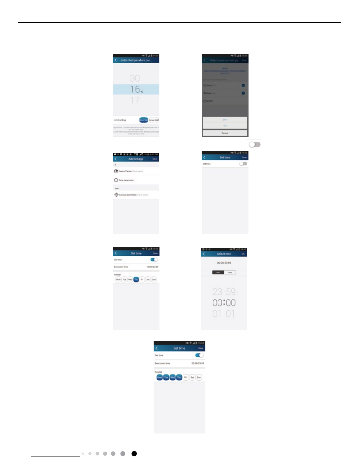
Tap "Temperature" to enter the page "Select temperature parameter". Slide up or down to adjust temperature. Tap "Upper limit" or
"Lower limit".
Tap "Mode" and "On/Off" to select the status of master device. Then tap "Save".
Step 2: Set time parameter for linkage. Tap "Time parameter" to enter the page "Set time". Slide rightwards to turn on the
setting time.
Tap "Execution time"; then tap "Start" and "Stop" to set start time and stop time respectively. Tap "OK" at the top right corner to save the
setting.

28
Service Manual
Technical Information
Tap the days below "Repeat" to select the repeating days. Then tap "Save".
Step 3: Select "Execute command"
Tap "Execute command" and enter the page "Select device".
Tap the name of device that you want to control. Tap "ON" or "OFF" and then tap "Save" to complete the linkage.
Tap "Save" and then repeat the above steps to set linkage of several scenes.

29
Service Manual
Technical Information
(5) Infrared control (only APPlicable to smart phones with infrared emitter).
Function: Smart phone can be used as a remote controller.
Tap at the top right corner of the homepage "Device". Select "Infrared" and enter the page "Remote controller". Tap and
slide up to enter the page of advanced functions.
Tap to turn on the device. Tap to select mode. Tap to adjust fan speed and swing angle. Tap "Health", "Energy
saving", "Sleep" etc. to set advanced functions.
Tap "Sleep" to enter the page "Sleep". You can select "Traditional sleep", "Expert sleep" or "DIY sleep". Tap "DIY sleep" and then tap
the left and right arrows to set sleep time. Tap up and down arrows to adjust temperature at a specic sleep time.
4.Menu functions
Menu functions (Share, Set, History, Feedback)
(1) Share: To share quick conguration information and unit’s information, including local export and local import.
For local import, you just need to tap "Local import" and wait for the data download.
Local export
Step 1: Export local data to another smart phone.
Enter "Menu" on the left side and tap "Share" to enter the page "Share". Then tap "Local export".

30
Service Manual
Technical Information
Step 2: Another smart phone to be imported.
Tap the model name and wait for the download.
(2) Backup: To keep backup of the quick conguration information and unit’s information, including backup to cloud and backup list on
the cloud.
Backup to cloud
Enter the "Menu" on the left and tap "Backup".
Tap "Backup to cloud" and then tap "Yes". Then wait for the data download.
Select "Backup list on the cloud". Then backup records will APPear. Tap "Record" to download data and recover data to local unit.

31
Service Manual
Technical Information
(3) Settings
User can set vibration, message alerts, server, updates, etc. The server setting here must be the same as the server setting in
"Conguration" mentioned before.
Otherwise, remote control will be invalid.
(4) Feedback
User can feedback suggestions to back-stage management for maintenance and development.
Tap "Feedback". Enter your suggestions and then submit it.

32
Service Manual
Technical Information
6.3 Operation of Smart Control (Smart Phone, Tablet PC)
Operation Instructions
Download and install APP
Scan the following QR code with your smart phone and download Wi Smart.
Conguration
1.Original conguration
Before operation, please nish the following conguration in order to realize Wi control and the connection between air conditioner and
intelligent device.
(1).Short-distance control setting for air conditioner using wi hotspot
Step 1: Air conditioner wi is set in APP mode in factory.
You can search the air conditioner wifi hotspot through your smart phone.The name of wifi hotspot is the last 8 numbers of the air
conditioner mac address. Password is 12345678.
Step 2: Open APP and the screen will show the air conditioner that you just connected. Tap the name of this air conditioner on your
phone to enter and realize short-distance control, as shown below. Please refer to "Functions introduction" for specic control methods.
Install the APP according to its guidance. When successfully installed, your smart phone homepage will show this icon
NOTE: Select either the original conguration or AP conguration according to the APP functions.
User of IOS system can search for the Wi Smart in Apple store to download the Apple version APP. Android user can
search "WiFi Smart" on Google Play to download it.
gree-a
gr-cn
gr-cn
gr-dh

33
Service Manual
Technical Information
2.Conguration method for Android phones
4 steps of conguration
Step 1: Enter homepage "Device", and then tap at the top right corner.
Select "Add device" and enter the page "Add device".
Tap "Manual conguration" and enter the page "Manual conguration".
Step 2: Tap "Next" in the First Step.
Step 3: Select the wireless network of air conditioner. APP will show the password 12345678 (default password of the network of air
conditioner). Then tap "Next"; select the name of home WiFi router, then enter the correct password and select a server.
Step 4: If conguration is successful, a window will pop up and read “WIFI module starts to connect the congured wireless router”.Then
conguration is completed.

34
Service Manual
Technical Information
NOTE: After conguration is completed, the air conditioner hot spot connected to your phone will disappear. You should reconnect your
phone to the home WiFi router to realize long-distance control.The above conguration only needs onephone. Other types of phones
shall install this APP, connect with the air conditioner hot spot or wireless router of WiFi air conditioner. When connection is done, open
the APP to use short-distance operation to control the air conditioner and then you can use the long-distance control.
3.Conguration method for Apple phones
Step 1: Turn on Wi-Fi “Settings” on the phone.
Step 2: In general, the hot spot signal of air conditioner is the last 8 bits of MAC address. Eg: Select “a0b41737” and enter
the defaulted password “12345678” to connect it.
Notice:
Finally, press “Conguration”, and APP will send the lled information to Wi Smart. At this time, the buzzer will give out a sound, which
indicates it has started to connect the wireless router.
Step 3: Turn on APP, press “+” button, press “Add device” to enter into the page of “Add device” and then select “Manual conguration”.
Enter wireless router’s SSID and PSW on the page of “Manual conguration”. The display on the server will be the same as the selection
when registering the account ( server selection in “Setting”).
Eg: WiFi name: Tenda_XXX;
WiFi password:123456789
Server: Europe
Check whether the filled information is correct. If the information is wrong, configuration will fail. Press “Configuration” to start
conguration.

35
Service Manual
Technical Information
If the name of router or the password is wrong, Wifi Smart can’t connect to the wireless router. 2 mins later, please conduct the
conguration operation again. Reset Wi-Fi adaptor by pointing you remote at the indoor unit and holding the mode and Turbo buttons on
your remote control for 10 seconds and until you hear the beep.
Wrong server selection will cause long-distance control invalid. Therefore, please make sure thatthe server selection when
registering the account is the same as this one.
If the password is blank, no password is defaulted for the wireless router, which is the OPEN mode.
Conguration should be conducted at one time. As for other phones, they can automatically search for the device after connecting to the
wireless router (such as Tenda_XXX) and turning on the APP.
Functions introduction
1.User registration
Purpose: To realize long-distance control.
Operation instruction: For the rst time login, you have to register a new username. If you already have a username, skip the registration
step and enter email address and password on the "Login Page" to log in. If password is forgotton, you can reset the password.
Operation steps:
(1) Select the sever address.
(2) Account login: Slide the page "Device", and enter the menu page on the left.Tap "Login" to enter the page "Register
username". New user must rst register a username. Tap "Register”.
(3) If password is forgotten, you can reset the password with your email address.
Tap "Forgot password" and enter the page "Forgot password". Enter your registered email account the rst. Tap "Get verication code" to
get an email verication code. Enter a new password and tap "OK" to log in.

36
Service Manual
Technical Information
2.Personal settings
Purpose: Set name (device name, preset name, etc.) and images (device image) in order to identify a user easily.
(1) Set device name
After quick conguration, a list of controllable smart devices will be generated. Default name for air conditioner is the last 8 numbers of
the air condtioner mac address.
Step 1: Tap and hold the Wi model name, such as “a0b417ac”, to enter the page "Edit device". Tap "Image" to select the source of
image. Select from "Default images " or " Take photo" or "Choose from photos" and save an image.
Step 2: Tap "Name" to change device name. Save it and the new device name will be shown. Enable button ''Lock device''to lock the
device so that other smart phones can’t search the device. Tap "Temperature unit" to change the temperature unit.
Notice: If this device is not locked, other phones within the local area network can be found through wi smart APP and operate the
device.
Step 3: Tap "Firmware update" to upgrade the rmware of the device. Tap"1.7" and then the device will be updated automatically.

37
Service Manual
Technical Information
(2) Set preset name
Step 1: Tap at the top right corner of the homepage "Device". Select "Add preset" and enter the page "Preset edit".
Step 2: Choose the time. Tap "Name". As shown in the picture, its name is "baby room". For timer type, select "On". Then select the
repeating days. Save the setting of preset name.
(3) Set device image
Please refer to step 1 in 2(1)
3.Control functions
(1) Common control functions: General control on the operation of smart devices (On/Off, temperature, fan speed, mode, etc.) and the
setting of advanced functions (air exchange, dry, health, light, sleep, energy saving upper limit).
Step 1: General control
Enter the homepage "Device" rst. Take "babyroom" as an example.

38
Service Manual
Technical Information
Tap "babyroom" and enter the page of air conditioner control. Tap to turn on the control switch.
Tap or to increase or decrease temperature. Tap to change working mode. Tap to enter the page of fan speed
adjustment.
Tap and go around the circle to adjust fan speed.
Step 2: Advanced settings
Tap to enter advanced settings. You may select "Air", "Dry", "Health", "Light", "Sleep" or "Energy saving".
(2) Advanced control functions; Set scene; Preset; Link: Infrared control(only applicable to smart phones with infrared emitter)
Set scene: Preset the operation of several smart devices by one tap. On the page "Device", tap the image of "Device" to enter the page
"Edit scene".
Tap "Add scene" and edit the scene name, for example, "Back home". Add execution devices.
Tap to add commands. On the page "Select execution device", select the air conditioner named "babyroom". Then select "ON" or
"OFF".

39
Service Manual
Technical Information
Continue to select the next execution device as instructed above. Tap to set the interval.
Tap "Save". Tap the scene picture displayed on homepage "Device" to send the command. Then the scene "Back home"
will be in execution. You may view the execution condition of the scene.
(3) Preset includes single-device preset and multi-device preset
Single-device preset: This can preset a certain device to be On/Off at a specic time.
On the homepage "Device", take air conditioner "babyroom" as an example. Tap at the bottom of the page "babyroom".
Then you will enter the page "Preset edit".
Slide up and down to set the time. If you need to synchronize the time, tap " synchronize". If such "Hint" interface doesn't
show up, please skip this operation step.

40
Service Manual
Technical Information
Tap "Name" to customize the preset name.
Preset device can’t be selected and it will default to "babyroom". Select "On" for the timer type. Select repeating days to complete the
preset.
Multi-device preset: This can preset multiple devices to execute a command at a specic time.
Please refer to the instructions as how to set preset time, name, timer type and repeating days for a single device.
Tap "Preset device" to select one or more devices. Then return to the page "Device".
(4) Link(This function is applicable to some models)
Select a master device. When the environment satisfies the parameters as set in the master device, slave devices will execute
commands to realize devices linkage.
Step 1: Set the parameters of master device (Select master device, select environment parameters, select master device status).
Tap at the top right corner of the homepage "Device". Select "Link" and enter the page "Add linkage". Tap "Device/Param" to enter
the page "Select device". Take "baby room" as an example. Tap "babyroom".
Enter the page "Select environment parameters".
41
Service Manual
Technical Information
Tap "Temperature" to enter the page "Select temperature parameter". Slide up or down to adjust temperature. Tap "Upper limit" or "Lower
limit".
Tap "Mode" and "On/Off" to select the status of master device. Then tap "Save".
Step 2: Set time parameter for linkage. Tap "Time parameter" to enter the page "Set time". Slide rightwards to turn on the setting
time.
Tap "Execution time"; then tap "Start" and "Stop" to set start time and stop time respectively. Tap "OK" at the top right corner to save the
setting.
Tap the days below "Repeat" to select the repeating days. Then tap "Save".
Step 3: Select "Execute command" Tap "Execute command" and enter the page "Select device".

42
Service Manual
Technical Information
Tap the name of device that you want to control. Tap "ON" or "OFF" and then tap "Save" to complete the linkage.
Tap "Save" and then repeat the above steps to set linkage of several scenes.
4.Menu functions
Menu functions (Share, Set, History, Feedback)
(1) Share: To share quick conguration information and unit’s information, including local export and local import.
For local import, you just need to tap "Local import" and wait for the data download.
Local export
Step 1: Export local data to another smart phone.
Enter menu page on the left side and tap "Share" to enter the page "Share". Then tap "Local export".

43
Service Manual
Technical Information
Step 2: Another smart phone to be imported.
Tap the model name and wait for the download.
Notice:
This function requires that the two phones are of the same operating system. They are either Android phones or Apple phones,and are
connecting to the same wireless router.
(2) Backup: To keep backup of the quick conguration information and unit’s information, including backup to cloud and backup list on
the cloud.
Backup to cloud
Enter the menu page on the left and tap "Backup".
Tap "Backup to cloud" and then tap "Yes". Then wait for the data download.
Select "Backup list on the cloud". Then backup records will appear. Tap "Record" to download data and recover data to local unit.

44
Service Manual
Technical Information
(3) Settings
User can set vibration, message alerts, server, updates, etc. The server setting here must be the same as the server setting in
"Conguration" mentioned before.
Otherwise, remote control will be invalid.
(4) Help
Please refer to “Help” of APP for the instruction of the latest functions.

45
Service Manual
Technical Information
6.4 Brief Description of Modes and Functions
1.Temperature Parameters
Indoor preset temperature (Tpreset)
Indoor ambient temperature (Tamb.)
2.Basic functions (The temperature in this manual is expressed by Centigrade. If Fahrenheit is used, the switchover between them
Tf=TcX1.8+32.)
Once the compressor is energized, there should be a minimum interval of 3 minutes between two start-ups. But if the unit is de-energized
and then energized, the compressor can restart within 3 minutes.
(1)Cooling mode
①
Cooling conditions and process
When Tamb. ≥Tpreset, the unit starts cooling operation. In this case, the compressor and the outdoor fan operate and the indoor fan
operates at set speed.
When Tamb. ≤Tpreset-2°C, the compressor will stop, the outdoor fan will delay 30 seconds to stop, and the indoor fan will run at the set
speed.
When Tpreset-2°C<Tamb.<Tpreset, the unit will maintain its previous running status.
In cooling mode, temperature setting range is 16~30°C; the indoor unit displays operation icon, cooling icon and set temperature.
②
When outdoor unit has malfunction or stops for protection, indoor unit will keep previous operation status and display malfunction
code.
(2)Dry Mode
When Tamb.>Tpreset, the unit operates in cooling mode. Meanwhile, compressor and outdoor fan operate, and indoor fan operates at
set fan speed (low fan speed, quiet fan speed or auto quiet fan speed).
When Tpreset-2°C<Tamb. ≤Tpreset, the unit keeps previous operation status.
When Tamb.≤Tpreset-2°C, the compressor will stop, the outdoor fan will stop with a time lag of 30s and indoor fan operate at set fan
speed (low fan speed, quiet fan speed or auto quiet fan speed).
Under this mode, the temperature setting range is 16~30°C. Display displays operation icon, drying icon and set temperature.
(3)Heating mode (not available for cooling only type)
①
Heating conditions and process
When Tamb. ≤Tpreset+2°C, the unit starts heating operation. In this case, compressor and outdoor fan operate simultaneously; the
indoor fan operates at cold-air prevention mode.
When Tamb.≥Tpreset+5°C,the compressor will stop, the outdoor fan will stop with a time lag of 30s; the indoor fan blows residual heat.
When Tpreset+2°C<Tamb.<Tpreset +5°C, the unit will maintain its previous running status.
Under this mode, temperature setting range is 16~30°C; the indoor unit displays operation icon, heating icon and set temperature.
Tpreset
Tpreset –2 ˚C
Compressor
Outdoor fan
Indoor fan
Run
Tamb.
Stop
Stop cooling
Start cooling
Original operating status
≥ 6 min.
30S 30S
≥ 3 min. ≥ 6 min.
Set fan speed
Tpreset
Tpreset –2 ˚C
Compressor
Outdoor fan
Indoor fan
Run
Tamb.
Stop
Stop drying
Start drying
Original operating status
≥ 6 min.
30S 30S
≥ 3 min. ≥ 6 min.
Set fan speed
Tpreset
Tpreset –2 ˚C
Compressor
Outdoor fan
Indoor fan
Run
Tamb.
Stop
Stop cooling
Start cooling
Original operating status
≥ 6 min.
30S 30S
≥ 3 min. ≥ 6 min.
Set fan speed
●
Indoor Unit

46
Service Manual
Technical Information
②
Defrosting and Oil Return
When receiving the signal of defrosting and oil return, the horizontal louver(big one) will rotate to the position where the angle is minimum
and the other horizontal louver(small one) will close. In 10 seconds later, indoor fan will stop operation. During defrosting, oil return and
5 minutes after quit, all indoor pipe temperature sensors will not be detected. When receiving oil return signal or defrosting signal sent by
outdoor unit, Heating indicator on indoor unit is off for 0.5s and then blinks for 10s.
③
Blow residual heat
In heating mode, when temperature reaches the set temperature, the compressor and outdoor fan will stop.
The horizontal louver (big one) will rotate to the default position for cooling and the other one (small one) will close. Indoor unit will
operate at set speed for 60s and then stop operation.
When the unit is in heating mode or auto heating mode, and also the compressor and indoor fan are operating, if turning off the
unit,compressor and outdoor fan will stop. Horizontal louver (big one) will rotate to the position where gentle wind is blown out (default
position for cooling) and the other horizontal louver (small one) will close. Indoor unit will operate at low speed for 10 seconds and then
the unit will be turned off.
(4)Fan Mode
In this mode, indoor fan operates at set speed while compressor and outdoor fan stop operation. The set temperature range is 16~30°C.
Operation icon and set temperature are displayed.
(5)Auto Mode
In this mode, operation mode (Cool, Heat, Fan) will be automatically selected according to change of ambient temperature. Operation
icon, actual operation icon and set temperature will be displayed. There is 30s delay for protection when changing mode. The protection
function is as the same as that under each mode.
①
When Tamb.≥26°C the unit will operate at cooling mode, the default set temperature is 25°C.
②
When Tamb. ≤21°C the unit will operate at heating mode, the default set temperature is 20°C if the cooling only unit operates at fan
mode, the default set temperature is 25°C;
③
When 22°C≤Tamb.≤25°C and the unit is turned on for the rst time, if it changes to auto mode from other mode, the previous operation
mode will be maintained; If it changes to auto mode from dry mode, the unit will operate at fan mode.
④
When the unit operates at auto mode, the frequency of compressor is as the same as that under cooling mode, while it is as the same
as that under heating mode.
Protection function
A. Under cooling mode, the protection function is as the same as that under cooling mode.
B. Under heating mode, the protection function is as the same as that under heating mode.
(6) “8°C” Heating
Under heating mode, press buttons “Temp” and “Clock” simultaneously, the 8°C heating function will be activated and “cold air prevention”
will be shielded.
①
8°C heating can’t co-exist with sleep function. If 8°C heating function is set, it can be cancelled by pressing sleep button, In that case,
the set temperature will be that before entering 8 heating; If sleep function is set, press buttons “Temp” and “Clock” simultaneously to
activate 8°C function and cancel sleep function at the same time.
②
Set temperature is 8°C and it is displayed on the indoor display panel.
Heating mode Tpreset
=20
(if cooling-only
unit, it is Fan mode,
T
preset=25
Keep current
operation mode
Cooling mode,
Tpreset=25
Tpreset
Tpreset +2 ˚C
Tpreset +5 ˚C
Tamb.
Compressor
Outdoor unit
Indoor unit
4-way valve
6 min.3 min.
2 min.
2 min.
Blow residual
heat
6 min.
Start heating
Previous running status
Start heating
Blow residual heat
Stop
Run
21℃ 26℃
T
preset
+5
T
preset
+2
Stop heating
Original operating status
Start heating
Run
Indoor fan
valve
Outdoor fan
Compressor
Stop
3min.6min. 6min.
T
amb
.
preset
Reversing
wind
60s
preset
wind
60s
30s
30s
<2 min.
<2 min.

47
Service Manual
Technical Information
③
In this mode, TURBO can’t be set and fan speed can’t be adjusted.
④
In this mode, when compressor operates, fan speed will be adjusted as follows; when compressor stops operation, indoor unit will
operate at blowing residual heat.
When Tindoor amb. ≤9°C, indoor fan operates at high fan speed;
When 9°C<Tindoor amb.<11°C, indoor fan operates at medium fan speed;
When Tindoor amb.≥11°C, indoor fan operates at low fan speed;
When changing among low high, medium, and low speeds, the minimum operation time is 210 seconds.
⑤
The unit with memory function can memorize 8°C heating mode.
(7)Energysaving Function
①
In cooling mode, when receiving command of energysaving sent by remote control, the controller enters energysaving mode; If the
unit is under energysaving mode already, such command will not be executed.
②
When remote control is set to display set temperature, “dual 8”nixie tube displays “SE”.
③
In this mode, when compressor operates, fan speed will be adjusted according to auto fan mode under energysaving operation;
when compressor stops operation, indoor fan will operate at low speed.
a. When Tamb.≥31°C, indoor fan will operate at super high speed;
b. When 31°C>Tamb.≥Tpreset+3°C, indoor fan will operate at high speed;
c. When Tpreset+1<Tamb.<Tpreset+3°C indoor fan will operate at medium speed;
d. When Tamb.≤Tpreset+1°C indoor fan will operate at low speed;
Note: The switchover among superhigh speed, high speed, medium speed and low speed requires minimum 210seconds of operation.
④
In this mode, set temperature will be automatically adjusted according to actual operation conditions.
3.Other Control
(1)Clock Timer
Timer ON
If timer ON is set during operation of the unit, the unit will continue to operate. If timer ON is set at unit OFF, upon ON time reaches the
unit will start to operate according to previous setting status.
Timer OFF
If timer OFF is set at unit OFF, the system will keep standby status. If timer OFF is set at unit ON, upon OFF time reaches the unit will
stop operation.
Timer Change
Although timer has been set, the unit still can be turned on/off by pressing ON/OFF button of the remote controller. You can also set
the timer once again, and then the unit will operate according to the last setting.
If timer ON and timer OFF are set at the same time during operation of the unit, the unit will keep operating at current status till OFF
time reaches.
If timer ON and timer OFF are set at the same time at unit OFF, the unit will keep off status till ON time reaches.
Each day in future, the system will operate according to preset mode till OFF time reaches and stop operation till ON time reaches. If
ON time and OFF time are the same, OFF command will prevail.
(2)Auto Button
If this button is pressed, the unit will operate in AUTO mode and indoor fan will operate at auto speed; meanwhile, the swing motor
operates. Press this button again to turn off the unit.
(3)Buzzer
Tamb.
Fan speed
Low
Med.
High
Tamb.
Tpreset + 3
31℃
11℃
9℃
Tp
Fan speed
Super high
High
Med.
Low
reset + 1
Tamb.
Fan speed
Low
Med.
High
11℃
9℃

48
Service Manual
Technical Information
Upon energization or availably operating the unit or remote controller, the buzzer will give out a beep.
(4)Sleep Function
Cooling mode、Dry mode: Basing on the set temperature of remote controller, after turning on the sleep function for a few hours, set
temperature will increase properly and automatically according to human body’s comfort.
Heating mode: Basing on the set temperature of remote controller, after turning on the sleep function for a few hours, set temperature will
decrease properly and automatically according to human body’s comfort.
(5)Turbo Function
This function can be set in cooling or heating mode to quickly cool or heat the room.
(6)X-FAN Function
①
When the unit is operating at COOL or DRY mode( it is not available under AUTO, HEAT, FAN modes), the X-FAN function can be
turned on/off. When it is turned on,once pressing ON/OFF button to turn off the unit, indoor fan will continue operation at low speed for 2
minutes. Within the 2 minutes, horizontal louver will keep its previous status while cold plasma and static dedusting will be forced to be
turned on and other loads will be turned off. Then the complete unit will be turned off; When X-FAN function is set to be off,once pressing
ON./OFF button, the complete unit will be turned on immediately.
②
During X-FAN operation, press X-FAN button, the indoor fan, horizontal louver, cold plasma and static-dedusting will be turned off
immediately.
(7)Control of Indoor Fan
Indoor fan can be set by remote control within the range of Mute, Fan speed 1, Fan speed 2, Fan speed 3, Fan speed 4, Fan speed 5
and Turbo and Fan will operate at low, med. high or super high speed accordingly. And also, auto fan speed can be set. Under auto fan
speed mode, indoor fan will automatically select high, med., low or mute speed according to change of ambient temperature.
①
Under Auto Heat mode or regular Heat mode, auto fan speed will be as follows:
When Tamb.<Tpreset-3°C, indoor fan will operate at high speed;
When Tpreset-3°C≤Tamb.<Tpreset+2°C indoor fan will operate at med. speed;
When Tpreset+2°C≤Tamb.<Tpreset+4°C, indoor fan will operate at low fan speed;
When Tamb≥Tpreset+4°C indoor fan will operate at mute.
Control Diagram of Auto Fan Speed under HEAT Mode
②
Under FAN or COOL mode: if it is auto cooling mode or regular cooling mode, auto fan speed will be as follows:
When Tamb.≥Tpreset+3°C, indoor fan will operate at high speed;
When Tpreset<Tamb.<Tpreset+3°C indoor fan will operate at med. speed;
When Tpreset-2°C<Tamb.≤Tpreset, indoor fan will operate at low speed;
When Tamb.≤Tpreset-2°C indoor fan will operate at mute;
③
There is no auto fan speed under DRY mode
Note: Fan speed “High”, “Med.” and “Low” are respectively corresponding to “Fan speed 5”, “Fan speed 3” and “Fan speed 1”. There is
210 seconds delay for fan speed switchover of auto fan.
(8)Vertical Swing
①
Small Horizontal Louver
After energization, vertical swing motor will rstly have the horizontal louver rotate anticlockwise to position O to close air outlet. If swing
function has not been set after startup of the unit, horizontal louver will turn clockwise to position D1 in HEAT mode. If swing function is
set when starting up the unit, the horizontal louver will swing between O and D1.There are 7 swing status of horizontal louver: Positions
O, A1, B1, C1 and D1, swing between O and D1 and stop at any position between L and D (angles between O and D1 are equiangular).
Upon turning off the unit, the horizontal louver will close at position O. Swing function is available only when
Tamb.
Tpreset +4ć
Tpreset +2ć
Tpreset -3ć
Fan speed
HighMed.Low Mute
Tamb.
Tpreset +3ć
Tpreset
Tpreset -2ć
Mute
Low High Med.
Fan speed

49
Service Manual
Technical Information
swing function is set and indoor fan is operating.
Note:
a. If the position is set between O and D1, A 1and C1 or B1 and D1 by remote controller, the horizontal louver will swing between O
and D1.
b. For model 9K/12K, only when big horizontal louver rotates to the second position for heating( 62°of corresponding angle), this
louver will be activated
c. Under cooling mode, this horizontal louver will be always in the position O.
②
Big Horizontal Louver
After energization, up & down swing motor will rstly have the horizontal louver rotate anticlockwise to position O to close air outlet.
If swing function has not been set after startup of the unit, horizontal louver will turn clockwise to position D in HEAT mode, or turn
clockwise to level position L in other modes. If swing function is set when starting up the unit, the horizontal louver will swing between
L and D.There are 7 swing status of horizontal louver: Positions L, A, B, C and D, swing between L and D and stop at any position
between L and D (angles between L and D are equiangular). Upon turning off the unit, the horizontal louver will close at position O.
Note: If the position is set between L and B, A and C or B and D by remote controller, the horizontal louver will swing between L and D.
(9)Horizontal Swing
Upon energization, the vertical louver will be reset to the start position rstly and then stop in the middle position. When setting
horizontal swing, there are 7 status: Position①, Position②, Position③, Positon④, Position⑤, swing between ①and ⑤ and
stop at any position between ①and ⑤. If setting horizontal swing during operation of the unit, the horizontal swing motor will drive
the louver to swing horizontally. When cancelling horizontal swing or it is not set when turning on the unit, the louver will stop in the
current.
(10)Display
①
Operation and Mode Icons
Upon energization, the unit will display all icons within 3 seconds. Under standby state, LED lamp of standby is on. If the unit is turned
on by remote controller, LED lamp of operation is on; meanwhile, the mark of current running mode will be displayed. If the light button
is turned off, no mark will be displayed.
②
Display of Nixie Tube on Indoor Unit
When energized & started for the rst time, the indoor unit defaults to displaying current set temperature (16~30°C). When set
temperature display is set by remote controller, it will display set temperature; when room temperature display is set, it will display
room or outdoor temperature. After that, when operating the remote controller for other settings, the temperature display method
will keep original. When operating the remote controller during room temperature display, the set temperature will be displayed for 5
seconds rstly and then room temperature display returns. If there is malfunction, corresponding malfunction code will be displayed.
For example, if ambient temperature sensor has malfunction, “F1” will be displayed; if indoor pipe temperature has malfunction, “F2”
Mute
Low High Med.
(0 degree)
Mute
(0 degree)
Low High Med.
(0 degree)
Th
is position is start point 0°

50
Service Manual
Technical Information
will be displayed; if jumper cap has malfunction, “C5” will be displayed.
(11)Memory Function
①
Memory when power failure upon turning on the unit
◆
Memory content: ON status, mode, up&down swing, light, set temperature, set fan speed, general timer, Fahrenheit/ Centigrade
◆
General timer can be memorized. Timer will be recalculated from the time of energization.
◆
Clock timer can’t be memorized.
②
Memory when power failure upon turning off the unit
◆
Memory content: ON status, mode, up&down swing, light, set temperature, set fan speed, general timer, Fahrenheit/ Centigrade
◆
General timer can be memorized. Timer will be recalculated from the time of energization.
◆
Clock timer can’t be memorized.
(12)I Feel function
When I FEEL command is received by controller, and also the ambient temperature is received from remote control, the controller will
operate according to the ambient temperature sent by the remote controller (For cold blow prevention, the unit operates according
to the ambient temperature sensed by the air conditioner). The remote controller will send ambient temperature data to the controller
for every 10 minutes. When the data has not been received for 11 minutes, the unit will operate according to the temperature sensed
by the air conditioner. If I FEEL function is not selected, the ambient temperature will be that sensed by the air conditioner. Ambient
temperature of I FEEL displayed by controller is 1 ~59°C.
(13)Health and Cold Plasma Function(Optional)
When the unit is operating, turn health or cold plasma to be ON/OFF by health button in remote control (if there is no such button in
remote control, the health is on as default). Only when health or cold plasma is turned on and indoor fan is operation, such function
can be activated.
(14)Static Dedusting Function(Optional)
When the unit is operating, turn static dedusting ON/OFF by health button in remote control (if there is no such button in remote
control, the health is on as default). Only when static dedusting is turned on and indoor fan is operation, such function can be
activated.
(15)Fahrenheit Display
Nixie tube displays current set temperature. If remote signal is Fahrenheit, the temperature will be displayed in Fahrenheit. The set
temperature range is 16~30°C. Under Auto mode, in COOL operation and FAN operation, 25°C will be displayed, while in HEAT
operation and FAN operation, 20°C will be displayed. For cooling-only controller, only 25°C will be displayed.
(16)Locked protection to Indoor Fan Motor
If the indoor fan motor keeps low rotation speed for a continuous period of time after startup, the unit will stop operation and
display“H6”.
(17)Mute Mode
①
Auto Mute: When selecting fan speed of auto mute, the fan speed will be adjusted according to change of ambient temperature;
when temperature meets the requirement of the setting, the unit will operate at lowest speed.
②
Mute mode: When selecting fan speed of mute, the unit will directly operate at lowest fan speed.
This position is start point
(18)Compulsive Defrosting Function
①
Start up compulsory defrosting function
Under ON status, set heating mode with remote controller and adjust the temperature to 16°C. Press “+, -, +, -, +,-” button
successively within 5s and the complete unit will enter into compulsory defrosting status. Meanwhile, heating indicator on indoor unit
will ON 10s and OFF 0.5s successively. (Note: If complete unit has malfunction or stops operation due to protection, compulsory
defrosting function can be started up after malfunction or protection is resumed.
②
Exit compulsory defrosting mode
After compulsory defrosting is started up, the complete unit will exit defrosting operation according to the actual defrosting result, and
the complete unit will resume normal heating operation.
(19)Refrigerant Recycling Function
①
Enter refrigerant recycling function
Within 5min after energizing (unit ON or OFF status is ok), continuously press LIGHT button for 3 times within 3s to enter refrigerant
recycling mode; Fo is displayed and refrigerant recycling function is started. At this moment, the maintenance people closes liquid
valve. After 5min, stick the thimble of maintenance valve with a tool. If there is no refrigerant spraying out, close the gas valve
immediately and then turn off the unit to remove the connection pipe.
②
Exit refrigerant recycling function
After entering refrigerant recycling mode, when receive any remote control signal or enter refrigerant recycling mode for 25min, the
unit will exit refrigerant recycling mode automatically If the unit is in standby mode before refrigerant recycling, it will be still in standby
mode after nishing refrigerant recycling; if the unit is in ON status before refrigerant recycling, it will still run in original operation
mode.

51
Service Manual
Technical Information
●
Outdoor Unit
1. Compensation function of input parameters
According to the structure of wall-mounting unit, considering the comfortability for operation, indoor ambient temperature when the
compressor is at OFF status is higher than set temperature under heating mode.
2. Control of detecting the availability of parameters
For ensuring the safety and reliability of operation, please insert the outdoor discharge temperature sensor into the corresponding
temperature sensor bushing to make sure that the control system can detect system discharge temperature accurately. Otherwise, the
unit will stop operation and it displays malfunction of discharge temperature sensor (discharge temperature sensor hasn’t been
inserted
well), which can only be resumed by pressing ON/OFF button on remote controller. Basic functions:
3. Cooling mode
3.1 Working condition and process for cooling
3.1.1 If compressor is at OFF status, and T
preset
-(T
indoor amb.
- T
indoor amb. compensation of cooling
) ≤0°C, the unit operates in cooling mode;
3.1.2 During cooling operation, if 0°C ≤ T
preset
-(T
indoor amb.
- T
indoor amb. compensation of cooling
) <3°C, the unit still operates in cooling mode;
3.1.3 During cooling operation, if 3°C ≤ T
preset
-(T
indoor amb.
- T
indoor amb. compensation of cooling
) , the unit stops operation when reaching the
temperature point in cooling.
3.2 under the mode,the temperature setting range is 16~30°C.
4. Dry mode
4.1 Working conditioner and process for drying is same as that for cooling mode;
4.2 Temperature setting range is 16~30°C;
5. Fan mode
5.1 Compressor, outdoor fan and 4-way valve are all turned off;
5.2 Temperature setting range is 16~30°C.
6. Heating mode
6.1 Working conditioner and process of heating(T
indoor amb.
is the actual temperature detected by indoor ambient temperature sensor;
△
T
indoor amb. compensation of heating
is indoor ambient temperature compensation during heating operation).
6.1.1 If compressor is at OFF status, and T
indoor amb.
- T
indoor amb. compensation of heating
-T
preset
≤-1°C, the unit operates in heating mode.
6.1.2 During heating operation, if 0°C≤ (T
indoor amb.
- T
indoor amb. compensation of heating
)-T
preset
<2°C, the unit still operates in heating mode.
6.1.3 During heating mode, if 2°C≤ (T
indoor amb.
- T
indoor amb. compensation of heating
)-T
preset
, the unit stops operation when reaching the temperature
point in heating.
6.2 Under this mode, the temperature setting range is 16~30°C.
7. Defrosting control heating mode
7.1 If it turns to defrosting time and it detected that the defrosting temperature is satised for 3mins successively, the unit turns into
defrosting process.
7.2 Defrosting-starting: compressor stops operation and restart it up after 90s delayed,
7.3 Defrosting-ending: Compressor stops operation and it starts up after 90s delayed.
7.4 When any one of below defrosting-ending conditions is satised, the unit will quit from defrosting operation:
7.4.1 T
outdoor tube≥Tquit temperature 1
for defrosting;
7.4.2 Defrosting operation time is reached T
max.defrosting time
.
8. Control of compressor
8.1 Frequecny of compressor intangibly controls the frequency according to the relation between ambient temperature and set
temperature, and the change speed of ambient temperature;
8.2 Under cooling, heating or drying mode, compressor will be started up after outdoor fan is started for 5s.
8.3 At the OFF status, stop operation because of protection and switchover to fan mode, the compressor stops operation immediately.
8.4 Under each mode: Once the compressor is started up, it can be stopped only after operation.
8.5 Under each mode, one the compressor is stopped, it can be restarted up only after 3min delayed
9. Control of outdoor fan
9.1 When turn off the unit by remote controller, stop operation because of protection or stop operation after reaching the temperature
point, outdoor can stop operation only after the compressor is stopped for 1min;
9.2 Under fan mode: outdoor fan stops operation.
9.3 defrosting-starting: enter into defrosting. Outdoor fan stops operation after compressor stops for 50s.
9.4 Defrosting-ending: quit defrosting. When the compressor stops operation, the outdoor fan operates.
10. Control of 4-way valve
10.1 4-way valve status under cooling, drying and fan modes: OFF;
10.2 When the unit turned on and operated in heating mode, the 4-way valve is energized immediately.
10.3 If turn off unit or switch to other mode in heating mode, the 4-way valve is de-energized after the compressor stops for 2min;
10.4 When the unit is turned off because of each protection, the 4-way valve is de-energized after 4 mins delayed.
10.5 Defrosting-starting: enter into defrosting. After the compressor stops for 50s, the 4-way valve will be de-energized.
10.6 Defrosting-ending: quit defrosting. After the compressor stops for 50s, the 4-way valve is energized.
11. Freeze protection
11.1 Under cooling or drying mode, After compressor is turned on in 6 min later, if T
inner tube≤Tlimit temperature of freeze protection
,operation frequency
of compressor will stop rising;If T
inner tube≤Tdecrease frequency temperature of freeze protection
, operation frequency of compressor may decrease;
11.2 Under cooling or drying mode, if it’s detected that T
inner tube≤Tstop operation temperature of freeze protection
for 3min successively, the unit will stop

52
Service Manual
Technical Information
operation due to freeze protection. If T
inner tube≥Ttemperature of freeze protection
and the compressor has stopped for 3min, the complete unit can
resume operation.
11.3 If the unit is stopped because of freeze protection for 6 times successively, it can’t resume operation automatically and the
malfunction will be displayed continuously, which can only be resumed by pressing ON/OFF button. During operation, if operation
time of compressor is over, the times of stop operation because of freeze protection will be cleared. If turn off the unit or switch to fan/
heating mode, malfunction and times of malfunction is eliminated immediately.
12. Overload protection
12.1 Overload protection under cooling or drying mode: If T
overload stop operation temp. in cooling≤Toutdoor tube
, the unit stops operation because of
overload in cooling; if T
outdoor tube
< T
overload limit-frequecny temp in cooling
and the compressor has stopped for 3min, the complete unit can resume
operation.
12.2 Under cooling or drying mode, if T
overload limit-frequecny temp. in cooling
≤T
outdoor tube
, the frequency of compressor may decrease;
12.3 Overload protection under heating mode: If T
overload stop operation temp. in heating≤Tindoor tube
, the unit stops operation because of overload in
heating; if T
indoor tube<Toverload limit-frequecny temp. in heating
and the compressor has stopped for 3min, the complete unit can resume operation.
12.4 Under heating mode, if T
overload limit-frequecny temp. in heating
≤T
indoor tube
, operation frequency of compressor may decrease;
12.5 If the unit is stopped because of overload protection for 6 times successively, it can’t resume operation automatically and the
malfunction will be displayed continuously, which can only be resumed by pressing ON/OFF button. During operation, if operation time
of compressor is over, the times of stop operation because of overload protection will be cleared. If turn off the unit, fan or switch to fan/
heating mode, malfunction and times of malfunction is eliminated immediately.
13. Discharge temperature protection of compressor
13.1 If T
stop operation temperature for discharge ≤Tdischarge
, the unit stops operation because of discharge protection; If T
discharge<Tnormal speed decreasefrequency for
discharge
and compressor has stopped for 3min, the complete unit can resume operation;
13.2 If T
normal speed decrease-frequency for discharge≤Tdischarge
, operation frequency of compressor may decrease;
13.3 If the unit is stopped because of discharge protection of compressor for 6 times successively, it can’t resume operation
automatically,which can only be resumed by pressing ON/OFF button. During operation, if operation time of compressor is over, the
times of stop operation because of discharge protection will be cleared. If turn off the unit, or switch to fan/heating mode, malfunction
and times of malfunction is eliminated immediately.
14. Current protection function
14.1 If I
AC current≥Ilimit frequency current for current protection
,operation frequency of compressor will stop rising;
If I
AC current≥Idecrease frequency current for current protection
,operation frequency of compressor may decrease;
If I
AC current≥Istop operation current for current protection
,the unit will stop operation because of overcurrent protection.
14.2 If the unit is stopped because of overcurrent for 6 times successively, it can’t resume operation automatically, which can only be
resumed by pressing ON/OFF button. During operation, if operation time of compressor is over, the times of stop operation because of
overcurrent protection will be cleared.
15. Voltage drop protection
During operation of compressor, if the voltage is decreasing quickly, the system may stop operation and voltage drop malfunction is
caused. 3min later, the system will be restarted up automatically.
16. Communication malfunction
When it hasn’t received the correct signal from indoor unit for 3min, the unit will stop operation because if communication malfunction;
If communication malfunction is eliminated and compressor has stopped for 3min, the complete unit can resume operation.
17. IPM module protection
After compressor is turned on, if the overcurrent happens for IPM module, or control voltage is too low because of abnormal causes,
IPM will detect module protection signal immediately. Once it detected the module protection signal, the unit will stop operation
because of module protection. If module protection is resumed and compressor has stopped for 3min, the complete unit will resume
operation.
If the unit is stopped because of module protection for 3 times successively, the unit can resume operation automatically unless press
ON/OFF button. If the operation time for compressor is over, the times of stop operation because of module protection will be cleared.
18. Overheat protection of module
18.1 If T
normal speed frequency-decreasing temp. of module≤Tmodule
, the operation frequency of compressor may decrease;
18.2 If T
stop operation temperature of module≤Tmodule
, the syste will stop operation for protection. If T
module
<T
frequency-limiting temperature of module
and compressor
has stopped for 3min, the complete unit will resume operation;
18.3 If the unit is stopped because of overheating of compressor module for 6 times successively, it can’t resume operation
automatically,which can only be resumed by pressing ON/OFF button. During operation, if operation time of compressor is over, the
times of stop operation because of compressor overheating protection will be cleared. If turn off the unit, or switch to fan mode, times of
malfunction is eliminated immediately.
19. Overload protection of compressor
19.1 If it detected that the overload switch for compressor is open for 3min successively, the complete unit will stop operation for
protection;
19.2 If overload protection is resumed and compressor has stopped for 3min, the complete unit can resume operation;
19.3 If the unit stops operation because of overload protection for compressor for 3times successively, it can’t resume operation
automatically, which can only be resumed by pressing ON/OFF button. After compressor has operated for 30min, overload protection
times for compressor will be eliminated.

53
Service Manual
Installation and Maintenance
1. Select the installation location according to the requirement of this manual.(See the requirements in installation
part)
2. Handle unit transportation with care; the unit should not
be carried by only one person if it is more than 20kg.
3. When installing the indoor unit and outdoor unit, a sufcient xing bolt must be installed; make sure the installation
support is rm.
4. Ware safety belt if the height of working is above 2m.
5. Use equipped components or appointed components during installation.
6. Make sure no foreign objects are left in the unit after nishing installation.
Electrical Safety Precautions:
7. Notes for Installation and Maintenance
Safety Precautions:
Important!
Please read the safety precautions carefully before installation and maintenance.
The following contents are very important for installation
and maintenance.
Please follow the instructions below.
●The installation or maintenance must accord with the
instructions.
●Comply with all national electrical codes and local
electrical codes.
●Pay attention to the warnings and cautions in this
manual.
●All installation and maintenance shall be performed by
distributor or qualied person.
●All electric work must be performed by a licensed
technician according to local regulations and the
instructions given in this manual.
●Be caution during installation and maintenance. Prohibit
incorrect operation to prevent electric shock, casualty and
other accidents.
1. Cut off the power supply of air conditioner before
checking and maintenance.
2. The air condition must apply specialized circuit and
prohibit share the same circuit with other appliances.
3. The air conditioner should be installed in suitable
location and ensure the power plug is touchable.
4. Make sure each wiring terminal is connected firmly
during installation and maintenance.
5. Have the unit adequately grounded. The grounding
wire can’t be used for other purposes.
6. Must apply protective accessories such as protective
boards, cable-cross loop and wire clip.
7. The live wire, neutral wire and grounding wire of
power supply must be corresponding to the live wire,
neutral wire and grounding wire of the air conditioner.
8. The power cord and power connection wires can’t be
pressed by hard objects.
9. If power cord or connection wire is broken, it must be
replaced by a qualied person.
Warnings
Improper installation may lead to re hazard, explosion,
electric shock or injury.
Installation Safety Precautions:
Part
Ⅱ
: Installation and Maintenance
10. If the power cord or connection wire is not long enough,
please get the specialized power cord or connection wire
from the manufacture or distributor. Prohibit prolong the wire
by yourself.
11. For the air conditioner without plug, an air switch must
be installed in the circuit. The air switch should be all-pole
parting and the contact parting distance should be more than
3mm.
12. Make sure all wires and pipes are connected properly and
the valves are opened before energizing.
13. Check if there is electric leakage on the unit body. If yes,
please eliminate the electric leakage.
14. Replace the fuse with a new one of the same specication
if it is burnt down; don’t replace it with a cooper wire or
conducting wire.
15. If the unit is to be installed in a humid place, the circuit
breaker must be installed.

54
Service Manual
Installation and Maintenance
Safety Precautions for Installing
and Relocating the Unit:
Warnings
To ensure safety, please be mindful of the following precautions.
1. When installing or relocating the unit, be sure to keep the
refrigerant circuit free from air or substances other than the
specied refrigerant.
Any presence of air or other foreign substance in the refrigerant
circuit will cause system pressure rise or compressor rupture,
resulting in injury.
2.When installing or moving this unit, do not charge the
refrigerant which is not comply with that on the nameplate or
unqualied refrigerant.
Otherwise, it may cause abnormal operation, wrong action,
mechanical malfunction or even series safety accident.
3.When refrigerant needs to be recovered during relocating
or repairing the unit, be sure that the unit is running in
cooling mode.Then, fully close the valve at high pressure
side (liquid valve).About 30-40 seconds later, fully close the
valve at low pressure side (gas valve), immediately stop
the unit and disconnect power. Please note that the time for
refrigerant recovery should not exceed 1 minute.
If refrigerant recovery takes too much time, air may be sucked in
and cause pressure rise or compressor rupture, resulting in injury.
4.During refrigerant recovery, make sure that liquid valve and
gas valve are fully closed and power is disconnected before
detaching the connection pipe.
If compressor starts running when stop valve is open and
connection pipe is not yet connected, air will be sucked in and
cause pressure rise or compressor rupture, resulting in injury.
5.When installing the unit, make sure that connection pipe is
securely connected before the compressor starts running.
If compressor starts running when stop valve is open and
connection pipe is not yet connected, air will be sucked in and
cause pressure rise or compressor rupture, resulting in injury.
6.Prohibit installing the unit at the place where there may be
leaked corrosive gas or ammable gas.
If there leaked gas around the unit, it may cause explosion and
other accidents.
7.Do not use extension cords for electrical connections. If
the electric wire is not long enough, please contact a local
service center authorized and ask for a proper electric wire.
Poor connections may lead to electric shock or re.
8.Use the specied types of wires for electrical connections
between the indoor and outdoor units. Firmly clamp the
wires so that their terminals receive no external stresses.
Electric wires with insufcient capacity, wrong wire connections
and insecure wire terminals may cause electric shock or re.

55
Service Manual
Installation and Maintenance
Main Tools for Installation and Maintenance
1. Level meter, measuring tape
4. Electroprobe
7. Electronic leakage detector
10. Pipe pliers, pipe cutter
2. Screw driver
5. Universal meter
8. Vacuum pump
11. Pipe expander, pipe bender
3. Impact drill, drill head, electric drill
6. Torque wrench, open-end wrench, inner
hexagon spanner
9. Pressure meter
12. Soldering appliance, refrigerant container

56
Service Manual
Installation and Maintenance
8. Installation
8.1 Installation Dimension Diagram
Space to the ceiling
Space to the wall
At least 15cm
At least 15cm
At least 15cm
At least 250cm
Space to the wall
Space to the obstruction
roolf eht ot ecapS
Space to the obstruction
Drainage pipe
Space to the wall
Space to the obstruction
Space to the obstruction
Space to the obstruction
At least 300cm
At least 50cm
At least 200cm
At least 30cm
At least 30cm
At least 50cm

57
Service Manual
Installation and Maintenance
Preparation before installation
Prepare tools
Read the requirements
for electric connection
select installation
location
Select indoor unit
installation location
Install wall-mounting
frame, drill wall holes
Connect pipes of indoor
unit and drainage pipe
Connect wires of indoor unit
Connect wires of outdoor unit
Bind up pipes and
hang the indoor unit
Make the bound pipes pass
through the wall hole and then
connect outdoor unit
Neaten the pipes
Vacuum pumping and leakage detection
Check after installation and test operation
Finish installation
Note: this flow is only for reference; please find the more detailed installation steps in this section
.
Select outdoor unit
installation location
Install the support of outdoor unit
(select it according to the actual situation)
Install drainage joint of outdoor unit
(only for cooling and heating unit)
Connect pipes of outdoor unit
Start installation
Fix outdoor unit
Installation procedures

58
Service Manual
Installation and Maintenance
No. Name No. Name
1 Indoor unit 8 Sealing gum
2 Outdoor unit 9 Wrapping tape
3 Connection pipe 10
Support of outdoor
unit
4 Drainage pipe 11 Fixing screw
5
Wall-mounting
frame
12
Drainage plug(cooling
and heating unit)
6
Connecting
cable(power cord)
13
Owners manual,
remote controller
7 Wall pipe
8.2 Installation Parts-checking
8.3 Selection of Installation Location
8.4 Electric Connection Requirement
8.5 Installation of Indoor Unit
1. Please contact the local agent for installation.
2. Dont use unqualied power cord.
1. Basic Requirement:
Installing the unit in the following places may cause
malfunction. If it is unavoidable, please consult the local dealer:
(1) The place with strong heat sources, vapors, ammable or
explosive gas, or volatile objects spread in the air.
(2) The place with high-frequency devices (such as welding
machine, medical equipment).
(3) The place near coast area.
(4) The place with oil or fumes in the air.
(5) The place with sulfureted gas.
(6) Other places with special circumstances.
(7) The appliance shall not be installed in the laundry.
1. Choosing Installation Iocation
Recommend the installation location to the client and then
conrm it with the client.
2. Install Wall-mounting Frame
(1) Hang the wall-mounting frame on the wall; adjust it in
horizontal position with the level meter and then point out the
screw xing holes on the wall.
(2) Drill the screw xing holes on the wall with impact drill (the
specication of drill head should be the same as the plastic
expansion particle) and then ll the plastic expansion particles
in the holes.
2. Indoor Unit:
(1) There should be no obstruction near air inlet and air outlet.
(2) Select a location where the condensation water can be
dispersed easily and wont affect other people.
(3) Select a location which is convenient to connect the
outdoor unit and near the power socket.
(4) Select a location which is out of reach for children.
(5) The location should be able to withstand the weight of
indoor unit and wont increase noise and vibration.
(6) The appliance must be installed 2.5m above oor.
(7) Dont install the indoor unit right above the electric
appliance.
(8) Please try your best to keep way from uorescent lamp.
3. Outdoor Unit:
(1) Select a location where the noise and outow air emitted by
the outdoor unit will not affect neighborhood.
(2) The location should be well ventilated and dry, in which
the outdoor unit wont be exposed directly to sunlight or strong
wind.
(3) The location should be able to withstand the weight of
outdoor unit.
(4) Make sure that the installation follows the requirement of
installation dimension diagram.
(5) Select a location which is out of reach for children and far
away from animals or plants.If it is unavoidable, please add
fence for safety purpose.
Note:
Air-conditioner Air switch capacity
12K 16A
1. Safety Precaution
(1) Must follow the electric safety regulations when installing
the unit.
(2) According to the local safety regulations, use qualified
power supply circuit and air switch.
(3) Make sure the power supply matches with the requirement
of air conditioner. Unstable power supply or incorrect wiring
may result in electric shock,re hazard or malfunction. Please
install proper power supply cables before using the air
conditioner.
(4) Properly connect the live wire, neutral wire and grounding
wire of power socket.
(5) Be sure to cut off the power supply before proceeding any
work related to electricity and safety.
(6) Do not put through the power before nishing installation.
(7) If the supply cord is damaged,it must be replaced by the
manufacturer,its service agent or similarly qualied persons in
order to avoid a hazard.
(8) The temperature of refrigerant circuit will be high, please
keep the interconnection cable away from the copper tube.
(9) The appliance shall be installed in accordance with national
wiring regulations.
2. Grounding Requirement:
(1) The air conditioner is rst class electric appliance. It must
be properly grounding with specialized grounding device
by a professional. Please make sure it is always grounded
effectively, otherwise it may cause electric shock.
(2) The yellow-green wire in air conditioner is grounding wire,
which can't be used for other purposes.
(3) The grounding resistance should comply with national
electric safety regulations.
(4) The appliance must be positioned so that the plug is
accessible.
(5) An all-pole disconnection switch having a contact separation
of at least 3mm in all poles should be connected in xed wiring.
(6) Including an air switch with suitable capacity, please note
the following table. Air switch should be included magnet
buckle and heating buckle function, it can protect the circuitshort and overload. (Caution: please do not use the fuse only
for protect the circuit)

59
Service Manual
Installation and Maintenance
Fig.1
Wall
Wall
Mark on the middle of it
Gradienter
Left
Right
(Rear piping hole)
(Rear piping hole)
Space
to the
wall
above
Space
to the
wall
above
Φ55mm Φ55mm
Outlet
pipe
Drain hose
Drain hose
Tape
Outlet pipe
Insulating pip
e
Torque wrenc
h
Open-end
wrench
Indoor pipe
Pipe
Union nut
Union nutPipe joint
Pipe
Hex nut diameter(mm) Tightening torque(N m)
Φ6 15~20
Φ9.52 30~40
Φ12 45~55
Φ16 60~65
Φ19 70~75
Refer to the following table for wrench moment of force
:
Left
Rear left
Right
Rear right
Cut off
the hole
Left Right
Drain hose
Insulating pip
e
(1) Pay attention to dust prevention and take relevant safety
measures when opening the hole.
(2) The plastic expansion particles are not provided and should
be bought locally.
(1) Add insulating pipe in the indoor drain hose in order to
prevent condensation.
(2) The plastic expansion particles are not provided.
(As show in Fig.10)
Fig.2
Fig.5 Fig.6
Fig.7
Fig.8
Fig.9
Fig.10
Fig.3
Fig.4
(3) Fix the wall-mounting frame on the wall with tapping screws
(ST4.2X25TA) and then check if the frame is rmly installed by
pulling the frame. If the plastic expansion particle is loose,
please drill another xing hole nearby.
3. Install Wall-mounting Frame
(1) Choose the position of piping hole according to the direction
of outlet pipe. The position of piping hole should be a little
lower than the wall-mounted frame.(As show in Fig.1)
5. Connect the Pipe of Indoor Unit
(1) Aim the pipe joint at the corresponding bellmouth.(As show
in Fig.5)
(2) Pretightening the union nut with hand.
(3) Adjust the torque force by referring to the following sheet.
Place the open-end wrench on the pipe joint and place the
torque wrench on the union nut. Tighten the union nut with
torque wrench.(As show in Fig.6)
(4) Wrap the indoor pipe and joint of connection pipe with
insulating pipe, and then wrap it with tape.(As show in Fig.7)
6. Install Drain Hose
(1) Connect the drain hose to the outlet pipe of indoor unit.(As
show in Fig.8)
(2) Bind the joint with tape.(As show in Fig.9)
4. Outlet Pipe
(1) The pipe can be led out in the direction of right, rear right,
left or rear left.(As show in Fig.3)
(2) When selecting leading out the pipe from left or right, please
cut off the corresponding hole on the bottom case.(As show in
Fig.4)
(2) Open a piping hole with the diameter of Φ55mm on the
selected outlet pipe position.In order to drain smoothly, slant
the piping hole on the wall slightly downward to the outdoor
side with the gradient of 5-10°.(As show in Fig.2)
Note:
Note:
5-10
°
Φ55m
m
Indoor
Outdoor
.

60
Service Manual
Installation and Maintenance
Fig.13
Note: The wiring connect is for reference only,
please refer to the actual one.
Wire clip
Wiring board
Grounding
wire
Connect to outdoor unit
brown
yellow-
green
N(1)
black
blue
2 3
(4) Put wiring cover back and then tighten the screw.
(5) Close the panel.
Indoor unit
Gas
pipe
Indoor and
outdoor power cord
Liquid
pipe
Drain hose
Band
Drain hose
Band
Connection pipe
Indoor power cord
Wiring cove
r
Screw
Panel
Power connection
wire
Cable-cross
hole
(1) All wires of indoor unit and outdoor unit should be
connected by a professional.
(2) If the length of power connection wire is insufcient, please
contact the supplier for a new one. Avoid extending the wire by
yourself.
(3) For the air conditioner with plug, the plug should be
reachable after nishing installation.
(4) For the air conditioner without plug, an air switch must be
installed in the line. The air switch should be all-pole parting
and the contact parting distance should be more than 3mm.
(1) The power cord and control wire cant be crossed or
winding.
(2) The drain hose should be bound at the bottom.
Do not bend the drain hose too excessively in order to prevent
blocking.
7. Connect Wire of Indoor Unit
(1) Open the panel, remove the screw on the wiring cover and
then take down the cover.(As show in Fig.11)
8. Bind up Pipe
(1) Bind up the connection pipe, power cord and drain hose
with the band.(As show in Fig.14)
(2) Reserve a certain length of drain hose and power cord
for installation when binding them. When binding to a certain
degree, separate the indoor power and then separate the drain
hose.(As show in Fig.15)
(3) Bind them evenly.
(4) The liquid pipe and gas pipe should be bound separately at
the end.
9. Hang the Indoor Unit
(1) Put the bound pipes in the wall pipe and then make them
pass through the wall hole.
(2) Hang the indoor unit on the wall-mounting frame.
(3) Stuff the gap between pipes and wall hole with sealing gum.
(4) Fix the wall pipe.(As show in Fig.16)
(5) Check if the indoor unit is installed rmly and closed to the
wall.(As show in Fig.17)
(2) Make the power connection wire go through the cable-cross
hole at the back of indoor unit and then pull it out from the front
side.(As show in Fig.12)
(3) Remove the wire clip; connect the power connection wire
to the wiring terminal according to the color; tighten the screw
and then x the power connection wire with wire clip.(As show
in Fig.13)
Note:
Note:
Note:
Indoor
Outdoor
Wall pipe
Sealing gum
Upper hook
Lower hook of
wall-mounting frame
Fig.11
Fig.12
Fig.14
Fig.15
Fig.16
Fig.17

61
Service Manual
Installation and Maintenance
(1) Take sufficient protective measures when installing the
outdoor unit.
(2) Make sure the support can withstand at least four times the
unit weight.
(3) The outdoor unit should be installed at least 3cm above the
oor in order to install drain joint.(As show in Fig.18)
(4) For the unit with cooling capacity of 2300W~5000W, 6
expansion screws are needed; for the unit with cooling capacity
of 6000W~8000W, 8 expansion screws are needed; for the
unit with cooling capacity of 10000W~16000W, 10 expansion
screws are needed.
(1) After tightening the screw, pull the power cord slightly to
check if it is rm.
(2) Never cut the power connection wire to prolong or shorten
the distance.
(1) The through-wall height of drain hose shouldnt be higher
than the outlet pipe hole of indoor unit.(As show in Fig.25)
(2) Slant the drain hose slightly downwards. The drain hose
cant be curved, raised and uctuant, etc.(As show in Fig.26)
Note:
Note:
Note:
U-shaped curve
Wall
Drain hose
The drain hos
can't raise
upwards
gas pipe
Liquid pipe
Liquid
valve
gas valve
Union nut
Pipe joint
Foot holes
Foot holes
Chassis
Outdoor drain join
t
Drain hose
Drain ven
t
8.6 Installation of Outdoor Unit
1. Fix the Support of Outdoor Unit(select it according to the
actual installation situation)
(1) Select installation location according to the house structure.
(2) Fix the support of outdoor unit on the selected location with
expansion screws.
5. Connect Outdoor Electric Wire
(1) Remove the wire clip; connect the power connection wire to
the wiring terminal according to the color; x them with screws.
(As show in Fig.23)
6. Neaten the Pipes
(1) The pipes should be placed along the wall, bent reasonably
and hidden possibly. Min. semidiameter of bending the pipe is
10cm.
(2) If the outdoor unit is higher than the wall hole, you must set
a U-shaped curve in the pipe before pipe goes into the room,
in order to prevent rain from getting into the room.(As show in
Fig.24)
(2) Fix the power connection wire with wire clip.
2. Install Drain Joint(Only for cooling and heating unit)
(1) Connect the outdoor drain joint into the hole on the chassis.
(2) Connect the drain hose into the drain vent.
(As show in Fig.19)
3. Fix Outdoor Unit
(1) Place the outdoor unit on the support.
(2) Fix the foot holes of outdoor unit with bolts.
(As show in Fig.20)
4.Connect Indoor and Outdoor Pipes
(1) Remove the screw on the right handle and valve cover of
outdoor unit and then remove the handle and valve cover.
(As show in Fig.21)
(2) Remove the screw cap of valve and aim the pipe joint at the
bellmouth of pipe.(As show in Fig.22)
(3) Pretightening the union nut with hand.
(4) Tighten the union nut with torque wrench .
Hex nut diameter(mm) Tightening torque(N m)
Φ6 15~20
Φ9.52 30~40
Φ12 45~55
Φ16 60~65
Φ19 70~75
Refer to the following table for wrench moment of force
:
Fig.18 Fig.19
Fig.20
Fig.21
Fig.22
Fig.23
Fig.24
Fig.25
Note: the wiring connect is for reference only,
please refer to the actual one.
Handle
Indoor unit connection
blue
blue
black brown
brown
(black)
yellowgreen
yellowgreen
LN
2 3N(1)
NL
POWER
.
A
t least 3cm above the floor
Handel
Valve cover

62
Service Manual
Installation and Maintenance
(3) The water outlet cant be placed in water in order to drain
smoothly.(As show in Fig.27)
Liquid valve
Gas valve
Refrigerant charging
vent
Nut of refrigerant
Charging vent
Vacuum pump
Piezometer
Valve cap
Lo Hi
Inner hexagon
spanner
Open
Close
The drain hose can't be fluctuant
The drain hose
can't be fluctuant
The water
outlet can't be
fluctuant
The water outlet
can't be placed
in water
1. Use Vacuum Pump
(1) Remove the valve caps on the liquid valve and gas valve
and the nut of refrigerant charging vent.
(2) Connect the charging hose of piezometer to the refrigerant
charging vent of gas valve and then connect the other charging
hose to the vacuum pump.
(3) Open the piezometer completely and operate for 10-15min
to check if the pressure of piezometer remains in -0.1MPa.
(4) Close the vacuum pump and maintain this status for 1-2min
to check if the pressure of piezometer remains in -0.1MPa. If
the pressure decreases, there may be leakage.
(5) Remove the piezometer, open the valve core of liquid valve
and gas valve completely with inner hexagon spanner.
(6) Tighten the screw caps of valves and refrigerant charging
vent.(As show in Fig.28)
1. Check after Installation
Check according to the following requirement after finishing
installation.
2. Test Operation
(1) Preparation of test operation
● The client approves the air conditioner installation.
● Specify the important notes for air conditioner to the client.
(2) Method of test operation
● Put through the power, press ON/OFF button on the remote
controller to start operation.
● Press MODE button to select AUTO, COOL, DRY, FAN and
HEAT to check whether the operation is normal or not.
● If the ambient temperature is lower than 16℃, the air
conditioner cant start cooling.
2. Leakage Detection
(1) With leakage detector:
Check if there is leakage with leakage detector.
(2) With soap water:
If leakage detector is not available, please use soap water for
leakage detection. Apply soap water at the suspected position
and keep the soap water for more than 3min. If there are air
bubbles coming out of this position, theres a leakage.
8.7 Vacuum Pumping and Leak Detection
8.8 Check after Installation and Test
Operation
Fig.26
Fig.27
Fig.28
NO. Items to be checked Possible malfunction
1
Has the unit been
installed rmly?
The unit may drop, shake or
emit noise.
2
Have you done the
refrigerant leakage test?
It may cause insufcient cooling
(heating) capacity.
3
Is heat insulation of
pipeline sufcient?
It may cause condensation and
water dripping.
4 Is water drained well?
It may cause condensation and
water dripping.
5
Is the voltage of power
supply according to the
voltage marked on the
nameplate?
It may cause malfunction or
damage the parts.
6
Is electric wiring and
pipeline installed
correctly?
It may cause malfunction or
damage the parts.
7
Is the unit grounded
securely?
It may cause electric leakage.
8
Does the power cord
follow the specication?
It may cause malfunction or
damage the parts.
9
Is there any obstruction
in air inlet and air outlet?
It may cause insufcient cooling
(heating) capacity.
10
The dust and
sundries caused
during installation are
removed?
It may cause malfunction or
damaging the parts.
11
The gas valve and liquid
valve of connection pipe
are open completely?
It may cause insufcient cooling
(heating) capacity.
12
Is the inlet and outlet
of piping hole been
covered?
It may cause insufcient cooling
(heating) capacity or waster
eletricity.

63
Service Manual
Installation and Maintenance
9. Maintenance
9.1 Troubleshooting for Normal Malfunction
The remote
controller does
not receive
signals (after it
is powered, the
buzzer will
sound, unless it
has
malfunction)
Trip of breaker or
blow of fuse
Air conditioner can not
start up
Measure insulation resistance
to ground to see if there is any
leakage.
The circuit or the part of the air
conditioner has malfunction.
They heat and break the insulation and lead to short circuit or
creepage. Measure the insulation resistance or eliminate the
malfunction one by one. If the
breaker itself has malfunction,
then replace the breaker.
The transformer connection is
loose or has bad c ontact or the
transformer has malfunction.
Fasten the wiring; measure the
output voltage of the transformer , if it is incorrect, change
the transformer.
No power
Check power supply circuit.
Power plug is not well plugged in
and poor connection.
Check if the plug is properly
plugged in and make the loose
contact firm.
Fuse of controller burnt out
The air conditioner does not
react after it is
powered ( after
the plug is
inserted, the
buzzer does not
sound and the
remote startup
has no
response)
Remote controller malfunction
Receiver loose or poor connection
Receiver is broken
Change controller fuse
Controller is broken
Check remote controller
Remote controller is short of power
Change batteries
First, press the manual switch
button AUTO,if there is no
response,check based on the
above methods. If it runs normally after pressing the button,
check again whether the installation position and the connection wire of the reception head
is correct. If it is correct,then replace the receiver or the remote
controller.
Power voltage is too low
Check the voltage. If it is lower than 10% of
the rated voltage, check the cause, improve
the power supply condition and add the sta-
bilized voltage power supply.
The breaker trips at once when it
is set to “ON”.
The breaker trips in few minutes
when it is set to “ON”.

64
Service Manual
Installation and Maintenance
Improper set of temperature
Adjust set temperature
If cooling (heating) load is
proper
Check the forecasted load of cooling (heating)
The refrigerant has leakage or is
insufficient
Check and fill the leakage, then
vacuumize it and supplement the re-
frigerant as required
Leakage between the high pres-
sure and the low pressure in-
side the compressor
Replace the compressor
Malfunction of four-way valveReplace the four-way valve
Local block of capillaryReplace the capillary
Blockage of cooling system
Judge whether the system is blocked by
observing the condensation of evapora-
tor and the pressure value of the high
pressure manometer and take measures
to deal with the system.
Malfunction of
refrigerant
flow
Heat insulation for the connection
pipes of the indoor unit and the out-
door unit is bad.
Make sure that heat insulation for the thick and thin pipes
is good. Heat insulation must also be provided for the
joint andthe exposed part of the copper pipe .
Block of outdoor heat ex-
changer
Clean the dust accumulated on the
surface of the heat exchanger.
Air filter were blocked
Clean the filter
Fan speed was set too slow
To set the fan speed to high or
middle speed
Air circulation
is insufficient
Fan rotation speed becomes
low
Capacitor
damage
Motor damage
Replace the
capacitor
Replace the motor
The installation position of the
outdoor unit is not appropriate.
Good ventilation must be provided for the
installation position of the outdoor unit.
The outdoor temperature is too high.
Properly install the rainproof plate or the sunproof plate. If the
maximum cool air still can not meet the requirement, it is sug-
gested to replace the air conditioner.
Keep certain air tightness indoors, t ry not to use
electricalappliance with large quantity of heat
The air tightness is not enough. People
come in and out too frequently. There
are heating devices indoors.
Poor COOL(HEAT) operation

65
Service Manual
Installation and Maintenance
The indoor fan motor is burned or
breaks or has the heat protector
malfunction.
Replace the fan motor or the defective part.
Wrong connection
Make the correction connection based on
the circuit drawing.
The fan capacitor has open circuit or
is damaged.
The fan does not
run when it is set
to supply air.
Replace the fan capacitor of the same type
and same specification.
The outdoor fan motor is damaged.
Replace the fan motor
Wrong connection
Make the correct connection based on the
circuit drawing
The outdoor fan capacitor is damaged.
Replace the fan capacitor
Malfunction of compressor
Replace the compressor
Breakage of running capacitor of
compressor
Replace the capacitor
The voltage is too low or too
high.
Manostat is recommended.
Wrong wire connection
Connect the circuit diagram correctly
The built-in heat protector of the
motor breaks frequently because the
motor is abnormal.
Replace the fan motor
Adjust the volume of the refrigerant
The refrigerant is not enough or is too
much.
Replace the capillary
The capillary is blocked and the tem-
perature rises.
The compressor does not run
smoothly or is stuck. The air discharge
valve is damaged
Replace the compressor
The protector itself has malfunction. Replace the protector
The compres-
sor is too hot
and leads to the
action of the
protector.
The protector itself has malfunction.
Use the multimeter to check whether the
contact of the compressor is on when it is
not overheated. If it is not on, then replace
the protector
In the cooling and
heating mode,
the compressor
runs, but the out-
door fan does not
run.
In the cooling
and heating
mode, the
outdoor fan
runs, but the
compressor
does not run.

66
Service Manual
Installation and Maintenance
Adjust fan location
Fan of indoor unit contacts other parts
Foreign object in indoor unit
Take out the foreign object
Adjust support washer of compressor, and
tighten loosen screws
Touch of pipeline of outdoor unit Separate the touching pipeline.
Abnormal sound
and shake
Touch of inner plates
1. Tighten connect screw.
2. Stick absorbing clay between plates.
Louver of outdoor unit touched outer
case.
Adjust location of louver.
Abnormal sound inside compressor
Change compressor
Drainage pipe blocked or broken Change drainage pipe
Re-wrap and make it tight.
Wrap of refrigerant pipe joint is not
close enough.
Water leakage
Change controller
Wire loose or wrong connection
In cool, heat
mode, the
outdoor unit
and compres-
sor will not run.
Correctly wire according to the drawing
Improper setting of temperature
Adjust setting temp.
Controller malfunction (IC2003
broken, creepage of parallel capaci-
tor of relay loop, relay is broken etc.)
First, check whether the connection is
wrong. If no, replace the parts
The swing fan
does not run.
The torque of the swing motor is not
enough
Wrong connection
The controller is damaged(IC2003 is
damaged, the swing relay can not
close, etc)
Compressor shakes too much

67
Service Manual
Installation and Maintenance
9.2 Error Code List
No. Malfunction Name
Dual-
8 Code
Display
Display Method of Outdoor Unit
A/C status Possible Causes
Indicator has 3 kinds of display
status and during blinking, ON
0.5s and OFF 0.5s
Yellow
Indicator
Red
Indicator
Green
Indicator
1
High pressure
protection of
system
E1
During cooling and drying
operation, except indoor fan
operates, all loads stop operation.
During heating operation, the
complete unit stops.
1. Refrigerant was superabundant;
2. Poor heat exchange (including
lth blockage of heat exchanger
and bad radiating environment
);Ambient temperature is too high.
2
Antifreezing
protection
E2
OFF 1s
and blink
3 times
During cooling and drying
operation, compressor and
outdoor fan stop while indoor fan
operates.
1. Poor air-return in indoor unit;
2. Fan speed is abnormal;
3. Evaporator is dirty.
3
Refrigerant
leakage
protection
F0
OFF 1s
and blink
9 times
The Dual-8 Code Display will
show F0 and the complete unit
stops.
1.Refrigerant leakage;
2.Indoor evaporator temperature
sensor works abnormally;
3.The unit has been plugged up
somewhere.
4
High discharge
temperature
protection of
compressor
E4
OFF 1s
and blink
7 times
During cooling and drying
operation, compressor and
outdoor fan stop while indoor fan
operates.
During heating operation, all loads
stop.
Please refer to the malfunction
analysis (discharge
protection,overload).
5
Overcurrent
protection
E5
OFF 1s
and blink
5 times
During cooling and drying
operation, compressor and
outdoor fan stop while indoor fan
operates.
During heating operation, all loads
stop.
1. Supply voltage is unstable;
2. Supply voltage is too low and
load is too high;
3. Evaporator is dirty.
6
Communication
Malfunction
E6
Always
ON
During cooling
operation,compressor stops while
indoor fan motor operates.
During heating operation, the
complete unit stops.
Refer to the corresponding
malfunction analysis.
7
High temperature
resistant
protection
E8
OFF 1s
and blink
6 times
During cooling
operation:compressor will stop
while indoor fan will operate.
During heating operation, the
complete unit stops.
Refer to the malfunction
analysis(overload, high
temperature resistant).
8
EEPROM
malfunction
EE
OFF 1s
and blink
11 times
During cooling and drying
operation, compressor will
stop while indoor fan will
operate;During heating operation,
the complete unit will stop
Replace outdoor control panel
AP1
9
Limit/decrease
frequency due to
high temperature
of module
EU
All loads operate normally,while
operation frequency for
compressor is decreased
Discharging after the complete
unit is de-energized for 20mins,
check whether the thermal
grease on IPM Module of outdoor
control panel AP1 is sufcient and
whether the radiator is inserted
tightly.If its no use, please replace
control panel AP1.
10
Malfunction
protection of
jumper cap
C5
Wireless remote receiver and
button are effective, but can not
dispose the related command
1. No jumper cap insert on
mainboard.
2. Incorrect insert of jumper cap.
3. Jumper cap damaged.
4. Abnormal detecting circuit of
mainboard.

68
Service Manual
Installation and Maintenance
No. Malfunction Name
Dual-
8 Code
Display
Display Method of Outdoor Unit
A/C status Possible Causes
Indicator has 3 kinds of display
status and during blinking, ON
0.5s and OFF 0.5s
Yellow
Indicator
Red
Indicator
Green
Indicator
11
Gathering
refrigerant
Fo
OFF 1s
and blink
17 times
When the outdoor unit receive
signal of Gathering refrigerant,the
system will be forced to run
under cooling mode for gathering
refrigerant
Nominal cooling mode
12
Indoor ambient
temperature
sensor is open/
short circuited
F1
During cooling and drying
operation, indoor unit operates
while other loads will stop;
during heating operation,the
complete unit will stop operation.
1. Loosening or bad contact of
indoor ambient temp. sensor and
mainboard terminal.
2. Components in mainboard fell
down leads short circuit.
3. Indoor ambient temp. sensor
damaged.(check with sensor
resistance value chart)
4. Mainboard damaged.
13
Indoor evaporator
temperature
sensor is open/
short circuited
F2
AC stops operation once reaches
the setting temperature.
Cooling,drying:internal fan motor
stops operation while other loads
stop operation;
Heating: AC stop operation
1. Loosening or bad contact of
Indoor evaporator temp. sensor
and mainboard terminal.
2. Components on the mainboard
fall down leads short circuit.
3. Indoor evaporator temp. sensor
damaged.(check temp. sensor
value chart for testing)
4. Mainboard damaged.
14
Outdoor ambient
temperature
sensor is open/
short circuited
F3
OFF 1s
and blink
6 times
During cooling and drying
operating, compressor stops while
indoor fan operates;
During heating operation, the
complete unit will stop operation
Outdoor temperature sensor
hasnt been connected well or
is damaged. Please check it by
referring to the resistance table for
temperature sensor)
15
Outdoor
condenser
temperature
sensor is open/
short circuited
F4
OFF 1s
and blink
5 times
During cooling and drying
operation, compressor stops while
indoor fan will operate;
During heating operation,the
complete unit will stop operation.
Outdoor temperature sensor
hasnt been connected well or
is damaged. Please check it by
referring to the resistance table for
temperature sensor)
16
Outdoor
discharge
temperature
sensor is open/
short circuited
F5
OFF 1s
and blink
7 times
During cooling and drying
operation, compressor will
sop after operating for about 3
mins,while indoor fan will operate;
During heating operation,the
complete unit will stop after
operating for about 3 mins.
1.Outdoor temperature sensor
hasnt been connected well or
is damaged. Please check it by
referring to the resistance table for
temperature sensor)
2.The head of temperature sensor
hasnt been inserted into the
copper tube
17
Limit/decrease
frequency due to
overload
F6
OFF 1s
and blink
3 times
All loads operate normally,while
operation frequency for
compressor is decreased
Refer to the malfunction
analysis(overload, high
temperature resistant)
18
Decrease
frequency due to
overcurrent
F8
OFF 1s
and blink
once
All loads operate normally,while
operation frequency for
compressor is decreased
The input supply voltage is too
low;System pressure is too high
and overload
19
Decrease
frequency due to
high air discharge
F9
OFF 1s
and blink
twice
All loads operate normally,while
operation frequency for
compressor is decreased
Overload or temperature is too
high;
Refrigerant is insufcient;
Malfunction of electric expansion
valve (EKV)
20
Limit/decrease
frequency due to
antifreezing
FH
OFF 1s
and blink
4 times
All loads operate normally,while
operation frequency for
compressor is decreased
Poor air-return in indoor unit or
fan speed is too low

69
Service Manual
Installation and Maintenance
No. Malfunction Name
Dual-
8 Code
Display
Display Method of Outdoor Unit
A/C status Possible Causes
Indicator has 3 kinds of display
status and during blinking, ON
0.5s and OFF 0.5s
Yellow
Indicator
Red
Indicator
Green
Indicator
21
Voltage for DC
bus-bar is too
high
PH
OFF 1s
and blink
13 times
During cooling and drying
operation, compressor will stop
while indoor fan will operate;
During heating operation, the
complete unit will stop operation.
1. Measure the voltage of position
L and N on wiring board (XT),
if the voltage is higher than
265VAC, turn on the unit after the
supply voltage is increased to the
normal range.
2.If the AC input is
normal,measure the voltage of
electrolytic capacitor C on control
panel (AP1),if its normal, theres
malfunction for the circuit, please
replace the control panel (AP1)
22
Voltage of DC
bus-bar is too low
PL
OFF 1s
and blink
12 times
During cooling and drying
operation, compressor will stop
while indoor fan will operate;
During heating operation, the
complete unit will stop
1. Measure the voltage of position
L and N on wiring board (XT),
if the voltage is higher than
150VAC,turn on the unit after the
supply voltage is increased to the
normal range.
2.If the AC input is
normal,measure the voltage of
electrolytic capacitor C on control
panel (AP1),if its normal, theres
malfunction for the circuit, please
replace the control panel (AP1)
23
Compressor Min
frequence in test
state
P0
Showing during min. cooling or
min. heating test
24
Compressor rated
frequence in test
state
P1
Showing during nominal cooling
or nominal heating test
25
Compressor
maximum
frequence in test
state
P2
Showing during max. cooling or
max. heating test
26
Compressor
intermediate
frequence in test
state
P3
Showing during middle cooling or
middle heating test
27
Overcurrent
protection of
phase current for
compressor
P5
During cooling and drying
operation, compressor will stop
while indoor fan will operate;
During heating operation, the
complete unit will stop operation.
Refer to the malfunction
analysis (IPM protection, loss
of synchronism protection and
overcurrent protection of phase
current for compressor.
28
Charging
malfunction of
capacitor
PU
During cooling and drying
operation, compressor will stop
while indoor fan will operate;
During heating operation, the
complete unit will stop
Refer to the part three—charging
malfunction analysis of capacitor
29
Malfunction
of module
temperature
sensor circuit
P7
During cooling and drying
operation, compressor will stop
while indoor fan will operate;
During heating operation, the
complete unit will stop
Replace outdoor control panel
AP1

70
Service Manual
Installation and Maintenance
No. Malfunction Name
Dual-
8 Code
Display
Display Method of Outdoor Unit
A/C status Possible Causes
Indicator has 3 kinds of display
status and during blinking, ON
0.5s and OFF 0.5s
Yellow
Indicator
Red
Indicator
Green
Indicator
30
Module high
temperature
protection
P8
"During cooling
operation,compressor will stop
while indoor fan will operate;
During heating operation,the
complete unit will stop"
After the complete unit is
deenergized for 20mins, check
whether the thermal grease on
IPM Module of outdoor control
panel AP1 is sufcient and
whether the radiator is inserted
tightly. If its no use, please replace
control panel AP1.
31
Overload
protection for
compressor
H3
OFF 1s
and blink
8 times
"During cooling and drying
operation, compressor will stop
while indoor fan will operate;
During heating operation, the
complete unit will stop operation."
Refer to the malfunction
analysis(overload, high
temperature resistant)
32 IPM protection H5
OFF 1s
and blink
4 times
"During cooling and drying
operation, compressor will stop
while indoor fan will operate;
During heating operation,the
complete unit will stop operation."
33
Internal motor(fan
motor) do not
operate
H6
Internal fan motor, external fan
motor, compressor and electric
heater stop operation,guide louver
stops at present location.
Refer to the malfunction
analysis(overload, high
temperature resistant)
34
Desynchronizing
of compressor
H7
"During cooling and drying
operation, compressor will stop
while indoor fan will operate;
During heating operation,the
complete unit will stop operation."
Refer to the malfunction
analysis (IPM protection,loss
of synchronism protection and
overcurrent protection of phase
current for compressor.
35 PFC protection HC
OFF 1s
and blink
14 times
"During cooling and drying
operation, compressor will stop
while indoor fan will operate;
During heating operation,the
complete unit will stop operation."
36
Outdoor DC fan
motor malfunction
L3
OFF 1s
and blink
14 times
Outdoor DC fan motor malfunction
lead to compressor stop operation
1. Bad contact of DC motor
feedback terminal.
2. Bad contact of DC motor control
end.
3. Fan motor is stalling.
4. Motor malfunction.
5. Malfunction of mainboard rev
detecting circuit.
37 power protection L9
OFF 1s
and blink
9 times
compressor stop operation and
Outdoor fan motor will stop 30s
latter,3 minutes latter fan motor
and compressor will restart
Refer to the malfunction
analysis (IPM protection,loss
of synchronism protection and
overcurrent protection of phase
current for compressor.
38
Indoor unit and
outdoor unit
doesn't match
LP
OFF 1s
and blink
16 times
compressor and Outdoor fan
motor can’t work
Refer to the malfunction analysis
39 Failure startup LC
"During cooling and drying
operation, compressor will stop
while indoor fan will operate;
During heating operation,the
complete unit will stop operation."
DC fan motor malfunction or
system blocked or the connector
loosed

71
Service Manual
Installation and Maintenance
No. Malfunction Name
Dual-
8 Code
Display
Display Method of Outdoor Unit
A/C status Possible Causes
Indicator has 3 kinds of display
status and during blinking, ON
0.5s and OFF 0.5s
Yellow
Indicator
Red
Indicator
Green
Indicator
40
Malfunction of
phase current
detection circuit
for compressor
U1
"During cooling and drying
operation,compressor will stop
while indoor fan will operate;
During heating operation,the
complete unit will stop"
To protect the electronical
components when detect high
power
41
Malfunction of
voltage dropping
for DC bus-bar
U3
"During cooling and drying
operation, compressor will stop
while indoor fan will operate;
During heating operation, the
complete unit will stop"
Indoor unit and outdoor unit
doesn't match
42
Malfunction of
complete units
current detection
U5
"During cooling and drying
operation,the compressor will stop
while indoor fan will operate;
During heating operating,the
complete unit will stop operation."
Refer to the malfunction analysis
43
The four-way
valve is abnormal
U7
If this malfunction occurs during
heating operation, the complete
unit will stop operation.
Replace outdoor control panel
AP1
44
Frequency
limiting(power)
OFF 1s
and blink
13 times
Supply voltage is unstable
45
Compressor
running
OFF 1s
and blink
once
Theres circuit malfunction on
outdoor units control panel
AP1,please replace the outdoor
units control panel AP1.
46
The temperature
for turning on the
unit is reached
OFF 1s
and blink
8 times
1.Supply voltage is lower than
AC175V;
2.Wiring terminal 4V is loosened
or broken;
3.4V is damaged, please replace
4V.
47
Frequency
limiting(module
temperature)
OFF 1s
and blink
11 times
Replace outdoor control panel
AP1
48
Normal
communication
OFF 0.5s
and blink
once
49
Defrosting
(Heating indicator
ON 10s OFF 0.5s)
Defrosting will occur in heating
mode.Compressor will operate
while indoor fan will stop
operation.
50
Malfunction
of detecting
plate(WIFI )
JF

72
Service Manual
Installation and Maintenance
9.3 Troubleshooting for Main Malfunction
1. Malfunction of Temperature Sensor F1, F2
●Indoor unit:
Start
Insert the temperature
sensor tightly
yes
Ma lfunction is
eliminated.
Make the parts upright
yes
Malfunction is
eliminated.
Replace the controller with
one of the same model
End
no
no
no
no
yes
ye
s
Malfunction is
removed.
no
yes
yes
no
Is the wiring
terminal between temperature
sensor and the controller loosened or
poor ly contacted?
Is there short circuit due to tri-pover
of the pa rts?
Is the temperature
sensor normal according to the
Resistance Table?
Replace it with a
temperature sensor
of the same model

73
Service Manual
Installation and Maintenance
2.
Malfunction of Blocked Protection of IDU Fan Motor H6
END
No
Yes
No
Ye
s
No
Yes
Yes
Yes
No
No
No
Yes
Yes
No
Turn the fan blades
by hand under
power-off condition
Whether the fan blades
can run smoothly?
Adjust the motor and blade
assembly so that rotor can run
smoothly.
Under power-off condition,
check whether the wiring terminal
between
indoor fan and main
board is loose.
Turn unit on
to check whether the
malfunction is
eliminated.
Turn unit on
to check whether the
malfunction is
eliminated.
Reinsert the wiring
terminal of indoor fan.
It's the malfunction of main board.
Replace a new main board that is
of the same model.
It's the malfunction of main board.
Replace a new main board that is
of the same model.
Replace a new main board that is
of the same model.
It's the malfunction of main board.
Then check whether the voltage
between terminal 2 and terminal 3
of the motor interface is 15VDC.
Connect power and restart the unit.
Test whether the voltage between terminal 1 and terminal 2
of motor interface is within 280~310VDC.
Then check whether there is voltage
between terminal 2 and terminal 4
of the motor interface.
It's the malfunction of motor.
Replace a new motor that is
of the same model.
Start

74
Service Manual
Installation and Maintenance
3.
Malfunction of Protection of Jumper Cap C5
Appearance of
the jumper cap
Troubleshooting for C5
malfunction
Is there jum per cap on the
mainboard
?
Is
the jumper cap inserted
correctly and
tightly
?
Replace the jumper cap
withthe same model
End
yes
yes
Assemble the jumper
cap with the same
model
no
Is malf unction
elim inated
no
yes
Insert the
jumper cap
tightly
Is malfunction
elim in ated
no
no
yes
Is malfunction
eliminated
no
yes
Replace the mainboard
with the same model.

75
Service Manual
Installation and Maintenance
4. Communication malfunction E6
Start
Cut off power, check if the wire
between indoor unit and outdoor
unit, and the wire inside electric
box are connected correctly
Connected correctly?
No
No
No
No
NoNo
No
End
Yes
Ye
s
Yes
Yes
Yes
Yes
Malfunction is
eliminated
Malfunction is
eliminated
Malfunction is
eliminated
Malfunction is
eliminated
Replace outdoor
mainboard
Replace indoor
mainboard
Communication wire
connection is broken?
Replace the
wire
Is there incorrect
match between the mainboard
and the display panel or between
the indoor and outdoor
mainboards?
Match them
according to
the requirement
Reconnect the wire
according to
wiring diagram
Yes

76
Service Manual
Installation and Maintenance
5. Malfunction of detecting plate(WIFI ) JF
Start
Is malfunction
eliminated
The end
check if the connection wire
are correctly connected
Replace the
detecting
plate
with the same model
Replace the mainboard
with the same model
Yes
Yes
No

77
Service Manual
Installation and Maintenance
(1) Capacitor charge fault (Fault with outdoor unit) (AP1 below refers to the outdoor control panel)
Main Check Points:
●Use AC voltmeter to check if the voltage between terminal L and N on the wiring board is within 210VAC~240VAC.
●Is the reactor (L) correctly connected? Is the connection loose or fallen? Is the reactor (L) damaged?
Fault diagnosis process:
N
Y
N
Y
N
Y
N
Y
N
Y
Turn on the unit
and wait 1 minute
Use DC voltmeter
to measure the
voltage on the two
ends of electrolytic
capacitor
Voltage higher than 200V?
Fault with the voltage
testing circuit on
control panel AP1
Replace the control
panel AP1
Measure the AC voltage between
terminal
L and N on wiring board
XT(power supply)
Voltage within
210VAC~250VAC?
Shut down the power
and repair the power
supply to restore the
range
210VAC~250VAC
power on and
restart the unit
If the fault is
eliminated?
Shut down the power and wait 20 mi
nutes;
or use DC voltmeter to measure the voltage
on the two ends of capacitor , until the
voltage is lower than 20V
Check the
connection of reactor
(L in the Electrical
Wiring Diagram)
If the wiring of
reactor L
is normal?
Connect the reactor
Laccording to Electrical Wiring Diagram correctly
Re-energize and
turn on the unit
If the fault is
eliminated?
End
Replace the control
panel AP1
●Outdoor unit:

78
Service Manual
Installation and Maintenance
(2) IPM Protection, Out-of-step Fault, Compressor Phase Overcurrent (AP1 below refers to the outdoor control
panel)
Main check points:
●Is the connection between control panel AP1 and compressor COMP secure? Loose? Is the connection in correct order?
●Is the voltage input of the machine within normal range? (Use AC voltmeter to measure the voltage between terminal L and N on the
wiring board XT)
●Is the compressor coil resistance normal? Is the insulation of compressor coil against the copper tube in good condition?
●Is the working load of the machine too high? Is the radiation good?
●Is the charge volume of refrigerant correct?
Fault diagnosis process:
Energize and
switch on
IPM protection
occurs after the
machine has run for
a
p
eriod of time?
Use AC voltmeter
to measure the
voltage between
terminal L and N
on the wiring
board XT)
If the voltage
between terminal L
and N on wiring
board XT is within
210VAC~250VAC?
Check the supply
voltage and
restore it to
210VAC~250VAC
Voltage between
the two ends of celectrolytic
capacitor is
Restart the unit. Before
protection occurs,
use DC voltmeter to
measure the voltage
between the two
ends of electrolytic
capacitor on control
panel AP1
If the unit can
work
normally?
Please confirm:
1. If the indoor and
outdoor heat
exchangers are
dirty? If they are
obstructed by other
objects which affect
the heat exchange
of indoor and
outdoor unit.
2. If the indoor and
outdoor fans are
working normally?
3. If the environment
temperature is too
high, resulting in
that the system
pressure is too high
and exceeds the
permissible range?
4. If the charge
volume of
refrigerant is too
much, resulting in
that the system
pressure is too
high?
5. Other conditions
resulting in that the
system pressure
becomes too high.
The connection
of capacitor C2
is loose.
Reconnect the
capacitor C2 according
to Electrical Wiring
Diagram. Then,
Restart the
unit.
Stop the unit and
disconnect the power
supply. Wait 20 minutes,
or use DC voltmeter to
measure the voltage
between the two ends of
capacitor C2, until the
voltage is lower than 20V
Replace the capacitor
C2. Then, energize
and start the unit.
Replace the
control panel AP1
Take corrective actions
according to Technical
Service Manual, and
then energize and start
the unit.
If there is any
abnormality
described above?
Replace the
control panel AP1
If the connection
between AP1 and
COMP is unsecure
or the connection
order is wrong?
Connect the control panel
A
P1 and compressor
COMP correctly according
to the Electrical Wiring
Diagram. Then, energize
and start the unit.
Use ohmmeter to
measure the resistance
between the three
terminals on compressor
COMP, and compare the
measurements with the
compressor resistance on
Service Manual.
If the
resistance is
normal?
Use ohmmeter to
measure the resistance
between the two
terminals of compressor
COMP and copper tube.
Replace the
compressor
COMP
Resistance higher
than 500MΩ?
Replace the
control panel
AP1
END
Y N
Y
N
Y
If the unit can
work normallv?
Y
If the unit can
work normally?
Y
N
Y
N
If the unit can
work normally?
Y
Y
N
N
If the unit can
work
normally?
Y
Y
N
N
N
Y
higher than
250V
Remove the wires
on the two ends of
capacitor C2. Then,
use capacitance
meter to measure
the capacitor C2.
Verify as per the
Parameters Sheet.
Stop the unit and
disconnect the power
supply. Then, check
the connection of
capacitor C2
according to Electrical
Wiring Diagram.
If capacitor
C2 is failed?
Refer to the
Electrical Wiring
Diagram and check
if the connection
between AP1 and
COMP is loose and if
the connection order
is correct.

79
Service Manual
Installation and Maintenance
(3) High temperature and overload protection diagnosis (AP1 hereinafter refers to the control board of the
outdoor unit)
Mainly detect:
●Is outdoor ambient temperature in normal range?
●Are the outdoor and indoor fans operating normally?
●Is the heat dissipation environment inside and outside the unit good?
Fault diagnosis process:
End
Y
N
Y
N
Y
N
Overheat and high
temperature protection
Is outdoor ambient temperature higher than 53?
20 minutes after the complete
unit is powered off.
Is heat dissipation of the indoor unit
and outdoor unit abnormal?
Normal protection, please operate
it after the outdoor ambient temperature is normalized.
Improve the heat
dissipation environment of the unit
Does the outdoor fan work normally?
1. Check if the fan terminal OFAN
is connected correctly
2. Resistance between any two
terminals is measure by an ohm
gauge and should be less than 1K
Ohm.
Replace the
control panel
AP1
Replace the fan
capacitor C1
Replace the
outdoor fan

80
Service Manual
Installation and Maintenance
(4) Start-up failure (following AP1 for outdoor unit control board)
Mainly detect:
●Whether the compressor wiring is connected correct?
●Is compressor broken?
●Is time for compressor stopping enough?
Fault diagnosis process:
Y
N
Y
N
N
Y
Y
N
Power on the unit
Is stop time of the compressor
longer than 3 minutes?
Restart it up after
3 minutes
Does startup fail?
Are the wires for the compressor connected
correctly? Is connection sequence right?
Connect the wires as
per the connection
diagram
Replace the control panel AP1
If the fault is eliminated?
Replace the
compressor
End

81
Service Manual
Installation and Maintenance
(5) Out of step diagnosis for the compressor (AP1 hereinafter refers to the control board of the outdoor unit)
Mainly detect:
●Is the system pressure too high?
●Is the input voltage too low?
Fault diagnosis process:
Out of step occurs once the
unit is powered on.
Is stop time of the
compressor longer than
3 minutes?
Are the wires for the compressor connected
correctly? Is connection sequence right?
Is the connection made in clockwise
direction?
Connect the
wires correctly
Replace the control
panel AP1
If the fault is eliminated?
Replace the
compressor
End
Out of step occurs in
operation
Is the outdoor fan working
normally?
Is the outdoor unit blocked
by foreign objects?
Replace the
control panel AP1
If the fault is eliminated?
Replace the
compressor
End
Check if the fan terminal
OFAN is connected correctly
Remove foreign objects
Replace the fan
capacitor C1
Replace the
outdoor fan

82
Service Manual
Installation and Maintenance
(6) Overload and air exhaust malfunction diagnosis (following AP1 for outdoor unit control board)
Mainly detect:
●Is the PMV connected well or not? Is PMV damaged?
●Is refrigerant leaked?
Fault diagnosis process:
20 minutes after the
complete unit is
powered off
Is the terminal FA for the
electronic expansion valve
connected correctly?
Connect the
wires correctly
Resistances between the first four pins
close to the terminal hole and the fifth
pin are almost the same, less than 100
ohm.
Replace the electronic
expansion valve
If the fault is eliminated?
If the fault is eliminated?
Replace the
control panel
AP1
Coolant leakage, refilling
the coolant
End

83
Service Manual
Installation and Maintenance
(7) Power factor correct or (PFC) fault (a fault of outdoor unit) (AP1 hereinafter refers to the control board of the
outdoor unit)
Mainly detect:
●Check if the reactor (L) of the outdoor unit and the PFC capacitor are broken
Fault diagnosis process:
Y
Y
N
N
N
N
N
N
Y
Y
Y
Start
Check wiring of the
reactor (L) of the
outdoor unit and the
PFC capacitor
Whether there is any
damage or
short-circuit?
Replace it as per the
wiring diagram and
reconnect the wires
If the fault is eliminated?
Remove the PFC capacitor
and measure resistance
between the two terminals.
Is the resistance around zero?
The capacitor is
short circuited and
the capacitor
should be replaced
Restart the unit
If the fault is eliminated?
Disconnect the terminals for the
reactor and measure the resistance
between the two terminals of the
reactor by an ohm gauge
Whether there is any damage
or short-circuit?
Replace the reactor
Restart the unit
If the fault is eliminated?
Replace the control
panel AP1
End
Y

84
Service Manual
Installation and Maintenance
(8) Communication malfunction: (following AP1 for outdoor unit control board)
Mainly detect:
●Is there any damage for the indoor unit mainboard communication circuit? Is communication circuit damaged?
●Detect the indoor and outdoor units connection wire and indoor and outdoor units inside wiring is connect well or not, if is there any
damage?
Fault diagnosis process:
Y
N
Y
N
N
Y
N
N
Y
N
Y
N
Y
Y
Start
Did the equipment operate
normally before the failure
occurs?
The AP1 voltage
detection circuit
is at fault
Check wiring inside of
the indoor and outdoor
units
Are wires broken?
Check the communication
circuit of the outdoor unit
If the fault is eliminated?
The communication
circuit is abnormal
Replace the main board
of
the indoor unit
End
If the fault is eliminated?
Replace the main board
AP1 of the outdoor unit
If the fault is eliminated?
Is the connection right?
Check the wiring of the indoor and
outdoor units with reference to the
wiring diagram
Correctly connect the
corresponding wires for
the indoor and outdoor
units with reference to
the wiring diagram

85
Service Manual
Installation and Maintenance
10. Exploded View and Parts List
10.1 Indoor Unit
39
34 33 32 31
30
29
28
26
27
25
24
23
22
21
20
19
13
14
16 1715
9
12
11
10
8
7654
3
1
2
36
37
38
35
18
The component picture is only for reference; please refer to the actual product.
MODE FAN
TURBO
SLEEPI FEEL
TIMER ON
TIMER OFF
CLOCK
QUIET
X-FAN TEMP LIGHT

86
Service Manual
Installation and Maintenance
No.
Description
Part Code
QtyGWH12TB-S3DBA3E/I
Product Code CB412N02902 CB412N02903
1 Front Panel 20022219T 20022240 1
2 Display Board 30565203 30565203 1
3 Filter Sub-Assy 1112211602 1112211602 1
4 Front Case Assy 20022256 20022256 1
5 Guide Louver 1051214702 10512127 1
6 Guide Louver 10512127 1051214702 1
7 Crank 10582070 10582070 1
8 Axile Bush 10542036 10542036 2
9 Helicoid Tongue sub-assy 2611224401 2611224401 1
10 Left Axile Bush 10512037 10512037 2
11 Stepping Motor 15212123 15212123 1
12 Propeller Axile Bush 1054202101 1054202101 1
13 Cross Flow Fan 10352033 10352033 1
14 Evaporator Assy 01002641 01002641 1
15 Evaporator Support 24212114 24212114 1
16 Cold Plasma Generator 1114001602 1114001602 1
17 Electrostatic Duster 11012027 11012027 1
18 Drainage Hose 05230014 05230014 1
19 Fan Motor 15012510 15012510 1
20 Wall Mounting Frame 01252484 01252484 1
21 Motor Press Plate 26112209 26112209 1
22 Rubber Plug (Water Tray) 76712012 76712012 1
23 Connecting pipe clamp 2611216402 2611216402 1
24 Rear Case assy 2220216104 2220216104 1
25 Axile Bush 10542036 10542036 2
26 Stepping Motor 15212125 15212125 1
27 Stepping Motor 15212126 15212126 1
28 Electric Box 20112181 20112181 1
29 Electric Box Cover 20122409 20122409 1
30 Jumper 4202300103 4202300103 1
31 Main Board 30138001028 30138001028 1
32 Electric Box Assy 10000204091 10000204091 1
33 Electric Box Cover2 2012207507 2012207507 1
34 Screw Cover 242520179 242520179 3
35 Pipe Connection Nut accessories 06320020 06320020 1
36 Connecting Cable 4002052317 4002052317 0
37 Temperature Sensor 390000598 390000598 1
38 Temperature Sensor 390000451 390000451 1
39 Remote Controller 30510119 30510119 1
40 Detecting plate(WIFI) 30070060 30070060 1
Above data is subject to change without notice.

87
Service Manual
Installation and Maintenance
No.
Description
Part Code
QtyGWH12TB-S3DBA1E/I GWH12TB-S3DBA2E/I
Product Code CB148N09102 CB411N03900
1 Front Panel 20012850T 20022255T 1
2 Display Board 30565140 30565145 1
3 Filter Sub-Assy 1112211602 1112211602 1
4 Front Case Assy 20012849 2001284902 1
5 Guide Louver 10512127 10512127 1
6 Guide Louver 10512147 1051214702 1
7 Crank 10582070 10582070 1
8 Axile Bush 10542036 10542036 2
9 Helicoid Tongue sub-assy 2611224401 2611224401 1
10 Left Axile Bush 10512037 10512037 2
11 Stepping Motor 15212123 15212123 1
12 Propeller Axile Bush 1054202101 1054202101 1
13 Cross Flow Fan 10352033 10352033 1
14 Evaporator Assy 01002641 01002641 1
15 Evaporator Support 24212114 24212114 1
16 Cold Plasma Generator 1114001602 1114001602 1
17 Electrostatic Duster 11012027 11012027 1
18 Drainage Hose 05230014 05230014 1
19 Fan Motor 15012510 15012510 1
20 Wall Mounting Frame 01252484 01252484 1
21 Motor Press Plate 26112209 26112209 1
22 Rubber Plug (Water Tray) 76712012 76712012 1
23 Connecting pipe clamp 2611216402 2611216402 1
24 Rear Case assy 2220216104 2220216104 1
25 Axile Bush 10542036 10542036 2
26 Stepping Motor 15212125 15212125 1
27 Stepping Motor 15212126 15212126 1
28 Electric Box 20112181 20112181 1
29 Electric Box Cover 20122409 20122409 1
30 Jumper 4202300103 4202300103 1
31 Main Board 30138001028 30138001028 1
32 Electric Box Assy 10000203582 100002001191 1
33 Electric Box Cover2 20122075 2012207507 1
34 Screw Cover 24252016 242520179 3
35 Pipe Connection Nut accessories 06320020 06320020 1
36 Connecting Cable 4002052317 4002052317 0
37 Temperature Sensor 390000598 390000598 1
38 Temperature Sensor 390000451 390000451 1
39 Remote Controller 30510119 30510119 1
40 Detecting plate(WIFI) 30110144 30110144 1
Above data is subject to change without notice.

88
Service Manual
Installation and Maintenance
12345
79
11
13
14
15
16
17
18
19
21222324252627
28
29
30
31
32
33
34
68
10
12
20
The component picture is only for reference; please refer to the actual product.
10.2 Outdoor Unit

89
Service Manual
Installation and Maintenance
Above data is subject to change without notice.
No.
Description
Part Code
QtyGWH12TB-S3DBA3E/O
Product Code CB412W02901
1 Front Grill 22413015 1
2 Cabinet 01433034P 1
3 Axial Flow Fan 10333011 1
4 Fan Motor 15013085 1
5 Electrical Heater (Chassis) 76510004 1
6 Chassis Sub-assy 0280311901P 1
7 Drainage Joint 26113009 1
8 Compressor Gasket 76710287 3
9 Compressor and Fittings 00103899G 1
10 Magnet Coil 4300008301 1
11 Compressor Overload Protector(External) 00180030 1
12 Valve Support Sub-Assy 01703242P 1
13 Valve Cover 22243005 1
14 Big Handle 2623343106 1
15 Cut off Valve Sub-Assy 03005700084 1
16 Cut off Valve Sub-Assy 03005700085 1
17 Wiring Clamp 26115004 1
18 4-Way Valve Assy 03073193 1
19 Reactor 43130185 1
20 Electrical Heater(Compressor) 76513004 1
21 Condenser Assy 01103000008 1
22 Electric Expand Valve Fitting 4300876717 1
23 Magnet Coil 4300008301 1
24 Flash Vaporizer Assy 07223054 1
25 Coping 01253034P 1
26 Motor Support Sub-Assy 01703180 1
27 Left Side Plate 01303169P 1
28 Electric Box Assy 10000100257 1
29 Electric Box Cover Sub-Assy 0260309601 1
30 Main Board 30148945 1
31 Electric Box 1 20113005 1
32 Terminal Board 42010313 1
33 Wire Clamp 71010003 1
34 Temperature Sensor 3900030905 1

90
Service Manual
Installation and Maintenance
11. Removal Procedure
11.1 Removal Procedure of Indoor Unit
Caution: discharge the refrigerant
completely before removal.
1. Before disassembling the unit
Before disassembling the unit.
2. Remove filter
Open the panel.
Loosen the clasps on filter, push the
filter inward and then pull it upward,
then the filter can be removed.
a
b
3.Remove guide louver
Remove the axial bushing of big
guidelouver.
a
axial bushing
Steps Procedure

91
Service Manual
Installation and Maintenance
Remove the rotating shaft of big guide louver
from the groove, slightly bend thebig guide
louver to remove it.
b
c Remove the axial bushing of small
guide louver.
Remove the rotating shaft of small guide
louver from the groove, slightly bend the
small guide louver to remove it.
d
big guide louver
axial bushing
small guide louver
4.Remove panel
aLoosen the clamps of the panel to remove
the panel.
Steps Procedure

92
Service Manual
Installation and Maintenance
panel, to remove the display.
5.Remove front case
Remove the screw fixing electric box
cover2 and remove the electric box cover2.
Remove the screw fixing detecting plate
and remove the detecting plate.
Note:
The position of detection board(WIFI)
may be different for different models.
electric box cover2
detecting plate
screw
screw
Remove the screws fixing front panel,
loosen the clamps, to remove the front
case.
screw
clamp
front case
Steps Procedure

93
Service Manual
Installation and Maintenance
6.Remove swing fan blade
a Loosen the clamps fixing swing connecting
rod, to remove the swing connecting rod.
b
remove the swing fan blade.
a Remove the indoor tube temp. sensor.
bRemove the screws fixing earth wire, to
remove the earth wire.
swing fan blade
clamp
clamp
swing connecting rod
7.Remove electric box sub-assy
heat exchanger thermistor
screw
earth wire
Steps Procedure

94
Service Manual
Installation and Maintenance
c
to remove the cover.
d Remove every wiring terminals, and remove the
electric box cover sub-assy.
a Remove the screws fixing connection pipe
clamp, to remove the connection pipe clamp.
7.Remove evaporator sub-assy
electric box cover sub-assy
screw
electric box cover
screw
auxiliary piping
pipe clamp
screw
Steps Procedure

95
Service Manual
Installation and Maintenance
bRemove the screws fixing evaporator
sub-assy, slightly regulate the tube, to
remove the evaporator sub-assy.
a
motor, to remove the motor.
b
to remove the motor.
8.Remove cross fan blade and motor
auxiliary piping
evaporator sub-assy
up&down swing motor
left&right swing motor
Steps Procedure

96
Service Manual
Installation and Maintenance
cRemove the screws fixing motor clamp,
to remove the motor clamp.
d Remove the cross fan blade and motor.
e Remove the shafting bearing cushion rubber
base
f
blade and motor, and then remove the motor.
screw
motor clamp
bearing cushion rubber base
cross fan blade
motor
Steps Procedure

97
Service Manual
Installation and Maintenance
11.2 Removal Procedure of Outdoor Unit
top cover
3. Remove panel and grille
2. Remove handle and valve cover
1. Remove top cover
handle
valve cover
panel
grille
Remove the screws connecting top cover, left and
right side plate, as well as panel, to remove the top
cover.
Remove the screws fixing panel, to remove the panel.
Remove the screws connecting panel grille and panel,
loosen the clamp, to remove the panel grille.
Remove the screws connecting handle and right side
plate, to remove the handle.Remove the screw fixing
valve cover, to remove the cover.
Step Procedure
 Loading...