

Gree GJC09AF-E6RNB3A, YX1F Service Manual

GREE ELECTRIC APPLIANCES,INC.OF ZHUHAI
Change for Life
Service Manual
M
odel:
GJC09AF-E6RNB3A
(Refrigerant:R32)

Service Manual
Table of Contents
Table of Contents
Part
Ⅰ
:Technical Information
............................................................. 1
1.Summary
...................................................................................................... 1
2.Specications
........................................................................................... 2
3.Outline Dimension Diagram
.............................................................. 4
4.Refrigerant System Diagram
............................................................ 5
5.Electrical Part
............................................................................................ 6
5.1 Wiring Diagram ........................................................................................... 6
5.2 PCB Printed Diagram .................................................................................. 7
6.Function and Control
............................................................................ 9
6.1 Introduction of Control Panel ....................................................................... 9
6.2 Introduction of Remote Controller ............................................................. 10
6.3 Function Introduction ................................................................................. 13
Part
Ⅱ
:Installation and Maintenance
............................................ 15
7.Notes for Installation and Maintenance
.................................... 15
8.Installation
................................................................................................ 18
8.1 Selection of Installation Location............................................................... 18
8.2 Electric Connection Requirement .............................................................. 18
8.3 Installation Procedure ............................................................................... 19
8.4 Installation of Accessories ......................................................................... 19
8.5 Drain Water ............................................................................................... 19
9.Maintenance
............................................................................................. 20
9.1 Malfunction Analysis .................................................................................. 20
9.2 Flashing LED of Indoor/Outdoor Unit and Primary Judgement ................. 25
10.Exploded View and Parts List
...................................................... 35
11.Removal Procedure
........................................................................... 37
Appendix:
...................................................................................................... 42
Appendix 1: Reference Sheet of Celsius and Fahrenheit ............................... 42
Appendix 2: List of Resistance for Ambient Temperature Sensor ................... 43
Service Manual
Technical Information
1
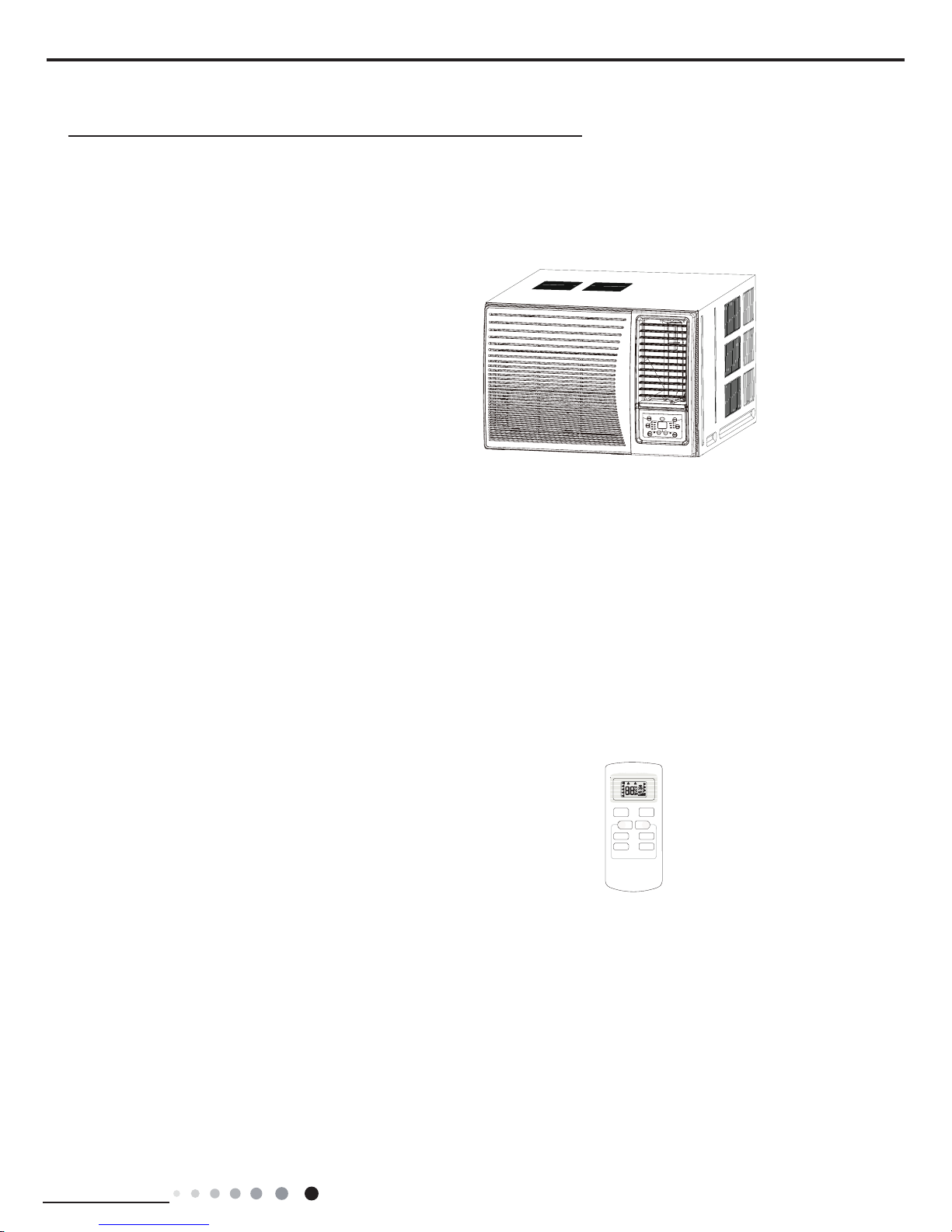
1.Summary
Remote Controller:
Model:
Part
Ⅰ
:Technical Information
GJC09AF-E6RNB3A
YX1F
AUTO
COOL
DRY
FAN
HEAT
T-ON T-OFF
SWING
SLEEP
LOCK
SPEED
+
_
ON/OFF
FAN SWING
SLEEP
TIMER
MODE
Service Manual
Technical Information
2
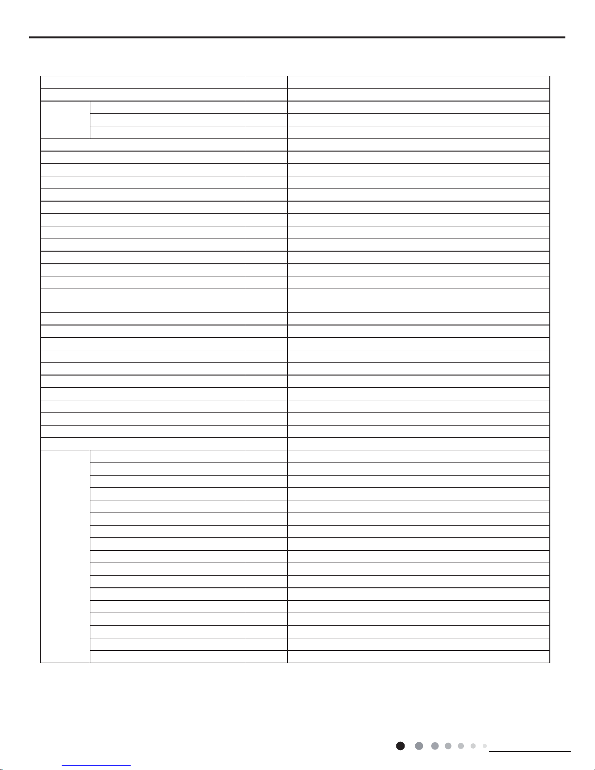
2.Specications
Model GJC09AF-E6RNB3A
Product Code CC055009900
Power
Supply
Rated Voltage V~ 230
Rated Frequency Hz 50
Phases 1
Cooling Capacity W 2700
Heating Capacity kJ/h /
Cooling Power Input W 782
Heating Power Input W /
Cooling Current Input A 3.5
Heating Current Input A /
Rated Input W 1100
Rated Current A 5.5
Air Flow Volume(H/M/L) m3/h 400/350/310
Dehumidifying Volume L/h 1
EER W/W 3.45
COP W/W /
Application Area m
2
12-18
Climate Type T1
Isolation I
Moisture Protection IP24
Design Pressure Hi. Side MPa 4.3
Design Pressure Low Side MPa 2.5
Dimension (WXHXD) mm 560/375/708
Dimension of Carton Box (LXWXH) mm 803/620/410
Dimension of Package (LXWXH) mm 806/623/425
Net Weight kg 43
Gross Weight kg 47
Refrigerant R32
Refrigerant Charge kg 0.51
Indoor Side
Fan Type Centrifugal
Fan Diameter Length(DXL) mm Φ193.1X80.9
Cooling Speed r/min 910/850/780
Heating Speed r/min /
Fan Motor Power Output W 60
Fan Motor RLA A 0.5
Fan Motor Capacitor μF 4
Electric Heating Power Input W /
Evaporator Form Aluminum Fin-copper Tube
Evaporator Pipe Diameter mm Φ7
Evaporator Row-n Gap mm 3-1.3
Evaporator Coil Length (LXDXW) mm 330X323.9X38.1
Swing Motor Model MP24VA
Swing Motor Power Output W 2.5
Fuse Current A 3.15
Sound Pressure Level (H/M/L) dB (A) 50/48/46
Sound Power Level (H/M/L) dB (A) 59/57/55
Service Manual
Technical Information
3
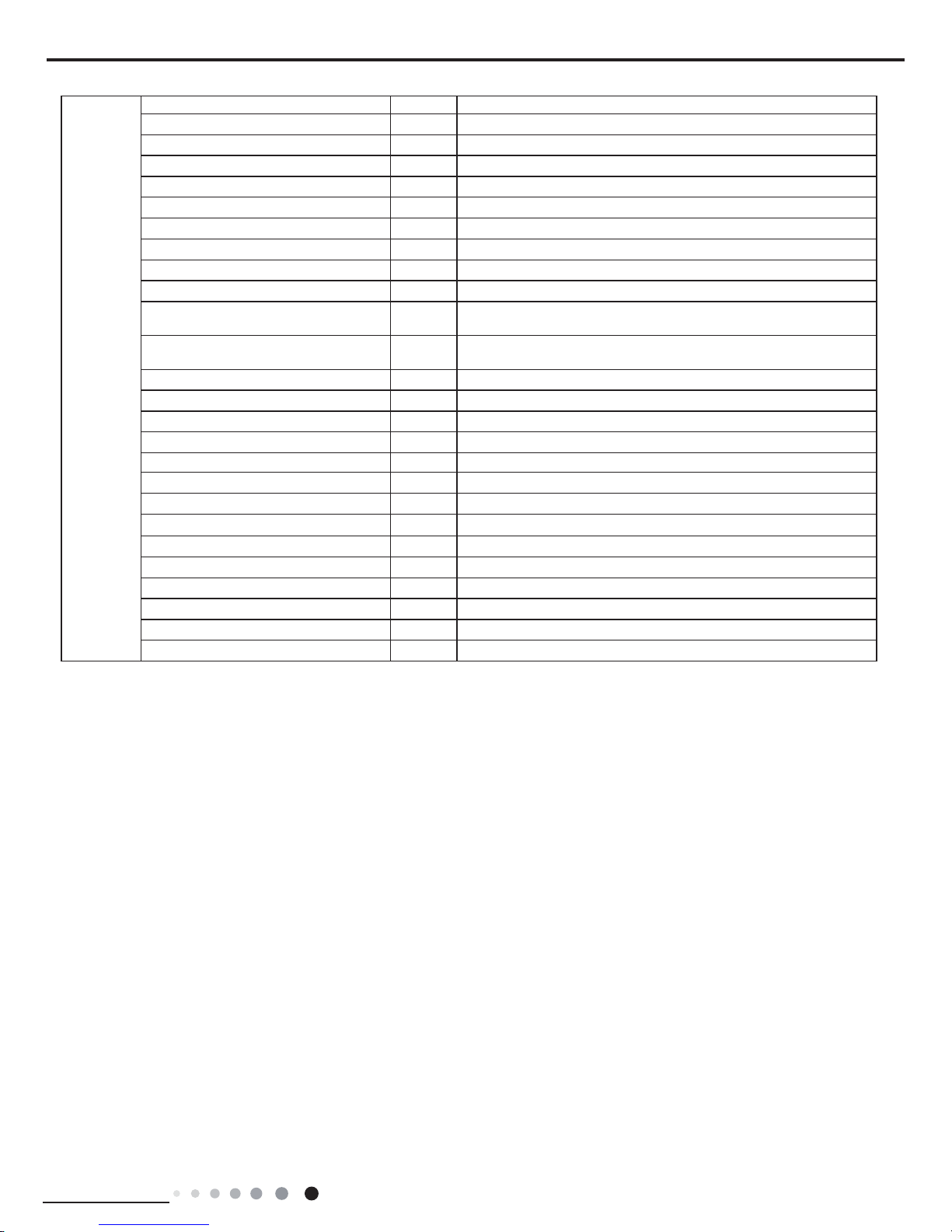
The above data is subject to change without notice; please refer to the nameplate of the unit.
Outdoor
Side
Compressor Manufacturer ZHUHAI LANDA COMPRESSOR CO.,LTD
Compressor Model QXF-A086zT190
Compressor Oil FW68DA or equivalent
Compressor Type Rotary
Compressor LRA. A /
Compressor RLA A 4.1
Compressor Power Input W 860
Compressor Overload Protector 1NT11L-6233/KSD115℃/HPC115/95U1
Throttling Method Capillary
Set Temperature Range
o
C 16~30
Cooling Operation Ambient Temperature
Range
o
C 16~43
Heating Operation Ambient Temperature
Range
o
C /
Condenser Form Aluminum Fin-copper Tube
Condenser Pipe Diameter mm Φ7
Condenser Rows-n Gap mm 2-1.4
Condenser Coil Length (LXDXW) mm 602.2X25.4X342.9
Fan Motor Speed (H/M/L) rpm 910/850/780
Fan Motor Power Output W 60
Fan Motor RLA A 0.5
Fan Motor Capacitor μF 4
Outdoor Unit Air Flow Volume CFM 800
Fan Type Axial-ow
Fan Diameter mm Φ353
Sound Pressure Level (H/M/L) dB (A) 56/54/52
Sound Power Level (H/M/L) dB (A) 65/63/61
Defrosting Method /
Service Manual
Technical Information
4
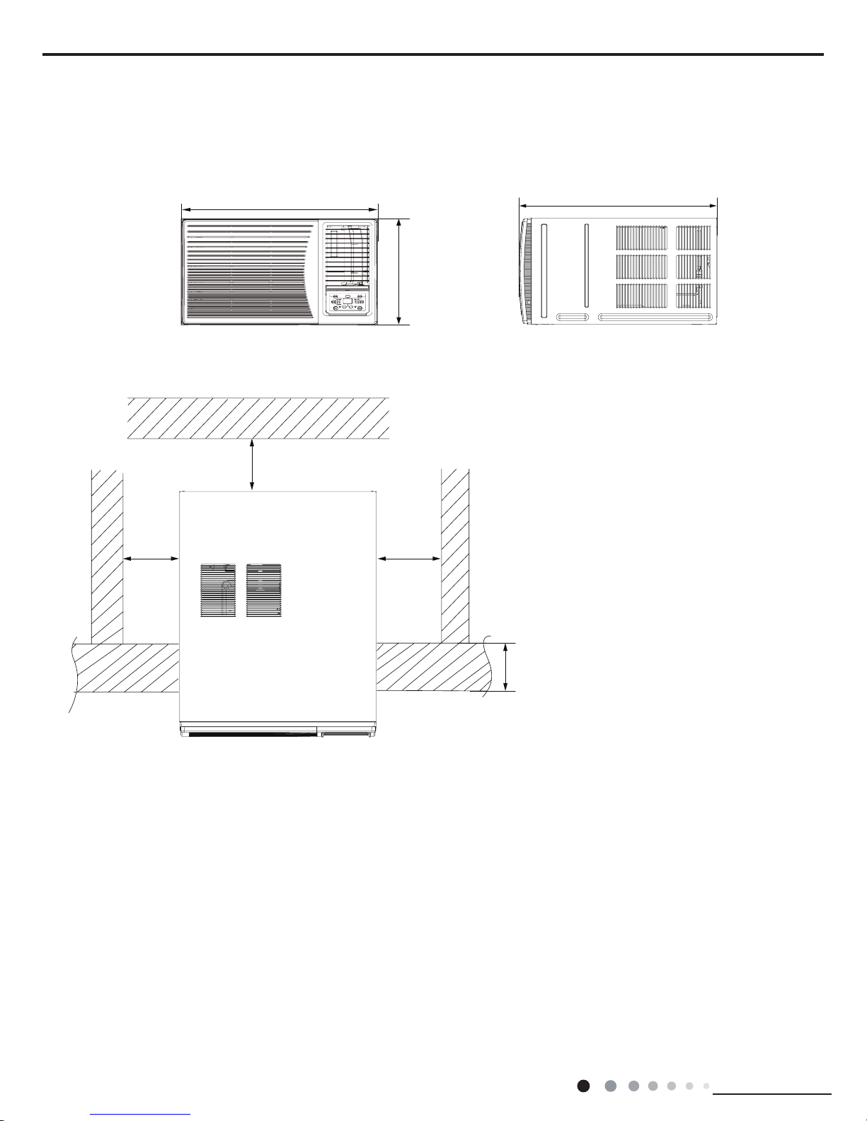
3.Outline Dimension Diagram
Unit:mm
Fence or
Likewise
Less than
220 mm
Over
150mm
Over
150mm
Over
500mm
Note: There must be no barriers within 1m in front of it.
708
560
375
Service Manual
Technical Information
5
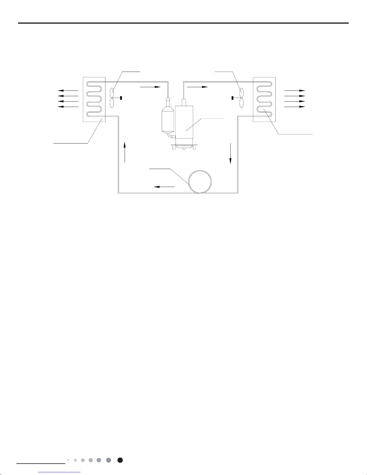
4.Refrigerant System Diagram
HOT DISCHARGED AI
R
OUTDOOR COILS
AXIAL FAN
COMPRESSOR
REFRIGERANT FLOW DIRECTION
CAPILLARY
CENTRIFUGAL
OR CROSS FAN
INDOOR COILS
COOLED AIR
Service Manual
Technical Information
6
5.Electrical Part
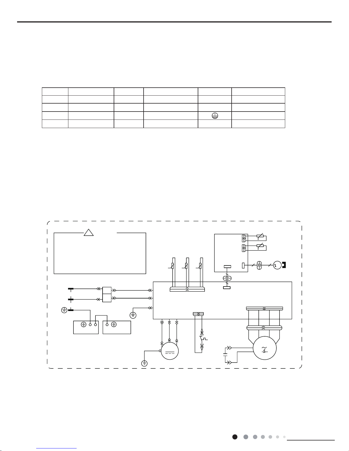
5.1 Wiring Diagram
●Electric Diagram
●Instruction
Symbol Symbol Color Symbol Symbol Color Symbol Name
WH White GN Green CAP. Capacitor
YE Yellow BN Brown COMP Compressor
RD Red BU Blue Grounding wire
YEGN Yellow-Green BK Black / /
;
)$1
3(
:
9
8
1
$&/
$3
%1
0
%8
<(*1
%8
<(
5'
&203
&203
)$102725
&1
:
9
8
&/$3%2$5'
<(*1
;7
29(5/2$'
5'
29&&203
6$7
5'
:$51,1*
.
.
.
&1
57
57 57
:+
%.
7(036(1625
28778%(
2875220
7(036(1625
(;+$867
7(036(1625
&$3
/
1
+
0
0$,1%2$5'
;
;
%.
<(
%8
:+
3527(&725
3(
7(50,1$/
%2$5'
έ
67(33,1*
02725
1
/
:+%8
*1<(*1
32:(5
%.%1
%1
5'
5220
78%(
6(1625
78%(7(03
6(1625
507(03
&1
$3
',63/$<
%2$5'
(/(&75,&%2;
3(
3(
<(*1
3(
3(
0
&210
Please don't touch any terminal
when the voltage of terminal
P(DC+) and N(DC-) at AP1 is
higher than 30V to prevent the risk
of electric shock !
These wiring diagrams are subject to change without notice; please refer to the one supplied with the unit.
Service Manual
Technical Information
7
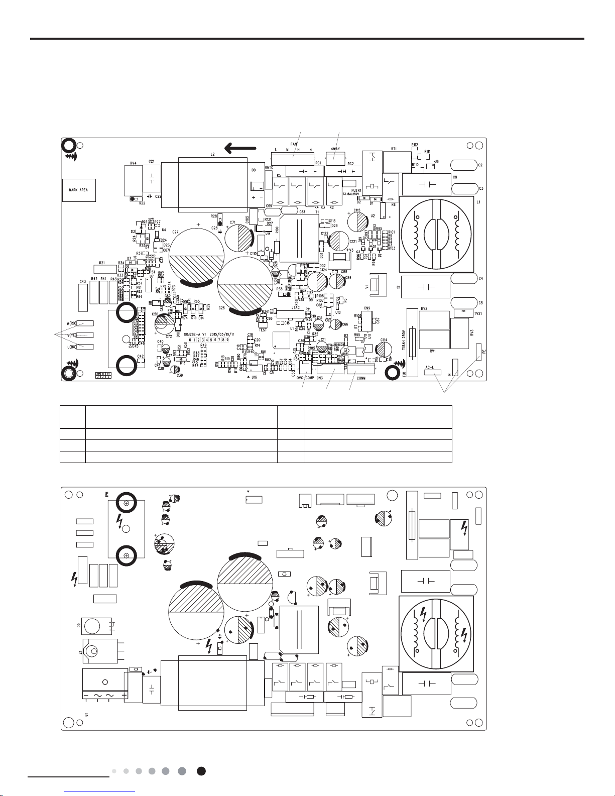
5.2 PCB Printed Diagram
5.2.1 Silk screen on main board
●Top view
●Bottom view
1
2
34
5
67
1
Interfaces for neutral wire, live wire and earthing
wire
5 U\V\W interface of compressor
2 Communication interface 6 Interface of AC fan
3 Interface of temperature sensor 7 Interface of 4-way valve (reserved)
4 Interface of overload protection of compressor
Service Manual
Technical Information
8
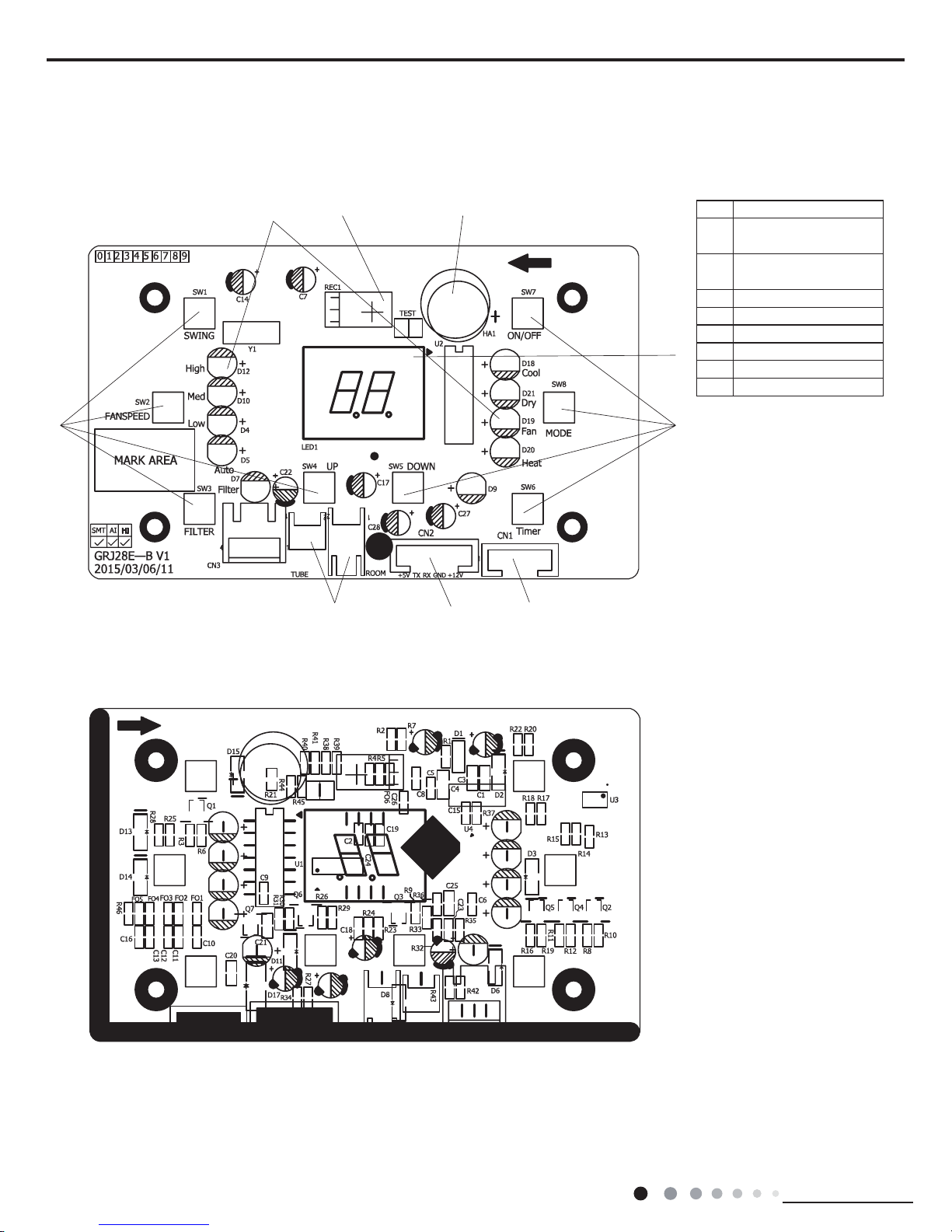
5.2.2 Silk screen on display board
●Top view
●Bottom view
1
23
4
5
6
7
8
9
1 Terminal of swing motor
2
Terminals connected
with main board
3
Interface of temperature
sensor
4 Buttons
5 LED indicator
6 Infrared receiver
7 Buzzer
8 dual-8 nixie tube display
9 Buttons
Service Manual
Technical Information
9
6.Function and Control
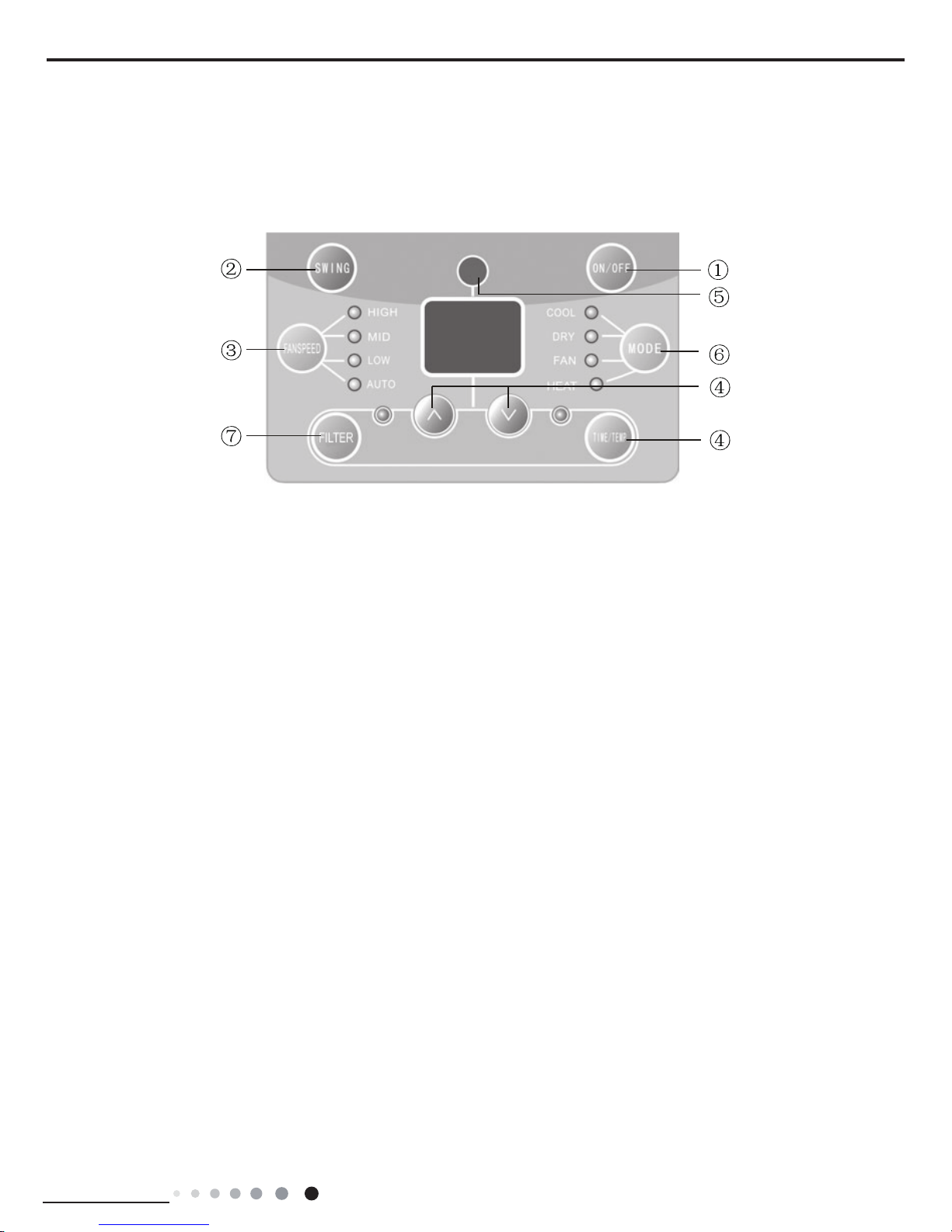
6.1 Introduction of Control Panel
After putting through the power, air conditioner will give out a sound and indicators on control panel will be on. After that, you operate the
air conditioner through remote controller or control panel.
Note:If wireless remote controller is lost, open the surface panel and operate manually.
1. POWER BUTTON
Operation starts when pressing this button, and stops when pressing this button again.
2.SWING BUTTON
Activate the automatic air swing function.
3.FAN SPEED BUTTON
Select the fan speed HIGH, MID, LOW and AUTO in sequence.
4.TEMP/TIMER BUTTON
①
Press the▲keypad to increase the set (operating) temperature of the unit.and Press the▼keypad to decrease the set (operating)
temperature of the unit.The temperature seting range is from 16~30
℃.
②
Press the▲keypad also to increase the selected time in 0.5h(1h) hour increments,and Press the▼keypad to decrease the selected
time in 0.5h(1h) hour decrements,The time seting range is from 0~24 hours.
Note:When operating the unit with control panel:when the timer range is 0~10h, the timer scale is 0.5h; when the timer range is 10~24h,
the timer scale is 1h. When operating the unit with remote controller, the timer scale is 0.5h.
③
Under on status, timer function can let the complete unit operate at COOL mode for a while and then switch to fan mode. The fan
mode is AUTO fan speed.
5.SIGNAL RECEIVER
6.MODE BUTTON
Select the operation mode, AUTO, HEAT, COOL, FAN,DRY (for reverse cycle model) or COOL,FAN, DRY(for cooling only model).
7.FILTER BUTTON
This feature is a reminder to clean the Air Filter (See Care and Cleaning) for more efcient operation and cooling. The LED (light) will
illuminate after 250 hours of operation. To reset after cleaning the lter, press the"Check Filter" button and the light will go off.
Service Manual
Technical Information
10
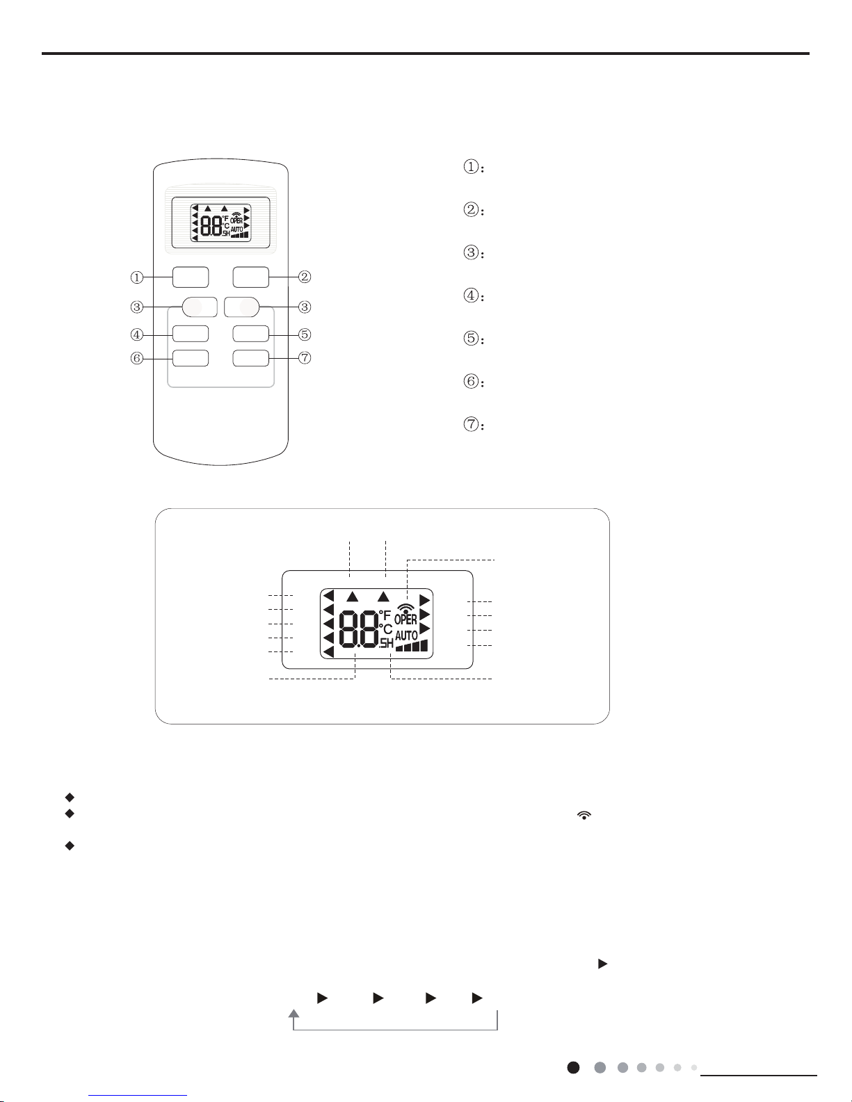
6.2 Introduction of Remote Controller
AUTO
COOL
DRY
FAN
HEAT
T-ON T-OFF
SWING
SLEEP
LOCK
SPEED
+
_
ON/OFF
FANSWING
SLEEP
TIMER
MODE
ON/OFF button
MODE button
+/- botton
FAN button
SWING button
SLEEP button
TIMER button
Icon Display on Remote
Controller
Operation introduction of remote controll
er
For auto operation
Timer on Timer off
Sending signal
For air swing
For sleeping
For locking
For setting fan speed
Set temperature
Set time
For cooling
For drying
For fan only
For heating
AUTO
COOL
DRY
FAN
HEAT
T-ON T-OFF
SWING
SLEEP
LOCK
SPEED
Buttons on Remote Controller
Note:
When power is connected(stand by condition), you can operate the air conditioner through the remote controller.
When unit is on, each time you press the button on remote controller, the sending signal icon on the display of remote controller
will blink once. If the air conditioner gives out a beep sound, it means the signal has been sent.
When unit is off, set temperature will be displayed on the remote controller(If the light of indoor unit display is turned on, the
corresponding icon will be displayed); When unit is on, it will display the icon of the on-going function.
1. ON/OFF Butto
n
Press this button to turn unit on/o
ff.
2. MODE Button
Pressing this button once can select your required mode circularly as below(the corresponding icon
will be lit up after the mode is
selected):
AUTO COOLDRY FANHEAT(For cooling and heating model)
Service Manual
Technical Information
11
When selecting auto mode, air conditioner will operate automatically according to ex-factory setting. Set temperature can't be
adjusted and won't be displayed either
. Press FAN button to adjust fan speed.
When selecting cool mode, air conditioner will operate under cool mode. Then press + or -- button to adjust set temperature. Press
FA
N button to adjust fan speed.
When selecting dry mode, air conditioner will operate at low fan speed under dry mode. In dry mode, fan speed can't be adjusted.
When selecting fan mode, air conditioner will operate in fan mode only. Then press FAN button to adjust fan speed.
When selecting heat mode, air conditioner will operate under heat mode. Then press + or -- button to adjust set temperature. Press
FA
N button to adjust fan speed. (This function is not available in this air conditioner.)
3. +/- butto
n
Pressing + or - button once will increase or decrease set temperature by 1 °F(°C). Hold + or -- button for 2s, set temperature on
remote controller will change quickl
y. Release the button after your required set temperature is reached.
When setting Timer On, Timer Off or Clock, press + or -- button to adjust the time (See TIMER Button for setting details).
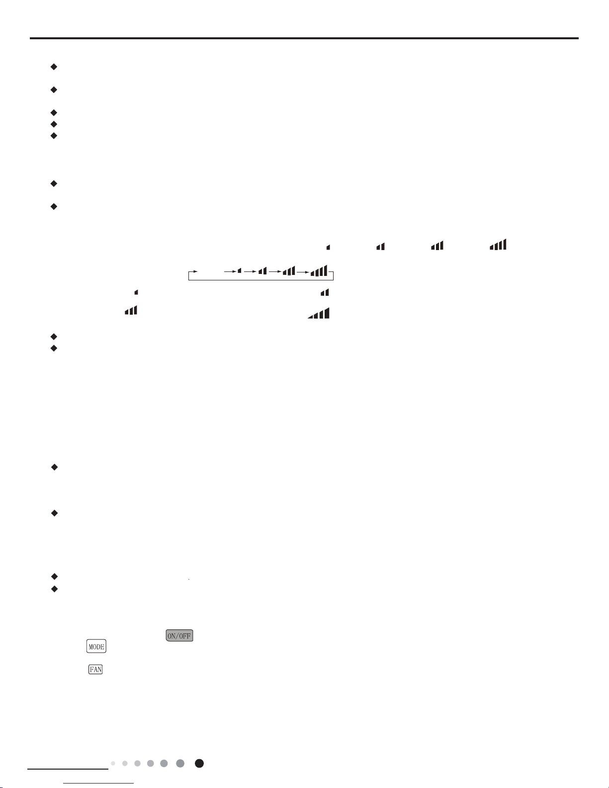
4. F
AN Button
Pressing this button can select fan speed circularly as:
AUTO, SPEED 1( ), SPEED 2( ), SPEED 3( ), SPEED 4( ) (unavailable
in this air conditioner
. Speed 4 is the same with speed 3).
Note
:
Under Auto mode, air conditioner will select proper fan speed automatically according to ex-factory setting.
Fan speed can't be adjusted under Dry mode.
5. SWING Butto
n
Press this button to turn on left & right air swing.
6. SLEEP
Button
Under Cool, Heat, Dry mode, press this button to turn on Sleep function. Press this button to cancel Sleep function. Under Fan
and
A
uto mode, this function is unavailable.
Simple operationfi
rst
1.After putting through power
“
” button on remote controller to turn on the air conditioner.
2.Press “
” button to select your required operation mode: AUTO, COOL, DRY, FA N.
3.Press “+” or “-” button to set your required temperature.(temperature can’t adjusted under
AUTO mode)
4.Press “
” button to select your required fan speed: auto, fi rst notch, second notch, third notch, fourth notch (fourthnotch is same
as third notch for this air conditioner
.)
SPEED 2 (equals to medium fan speed)SPEED 1 (equals to low fan speed)
SPEED 3 (equals to high fan speed)
AUTO
7. TIMER Button
When unit is on, press this button to set Timer Off. T-OFF and H icon will be blinking. Within 5s, press + or - button to adjust the
When unit is off, press this button to set Timer On. T-ON and H icon will be blinking. Within 5s, press + or - button to adjust the
time for Timer On. Pressing + or - button once will increase or decrease the time by 0.5h. Hold + or - button for 2s, time will change
quickly. Release the button after your required set time is reached. Then press TIMER button to confirm it. T-ON and H icon will stop
blinking.
Note:
Range of time setting is: 0.5~24h
The interval between two motions can't exceed 5s, otherwise the remote controller will exit setting status.
time for Timer Off. Pressing + or - button once will increase or decrease the time by 0.5h. Hold + or - button for 2s, time will change
quickly. Release the button after your required set time is reached. Then press TIMER button to confirm it. T-OFF and H icon will
stop blinking.
SPEED 4 (equals to high fan speed)
Service Manual
Technical Information
12
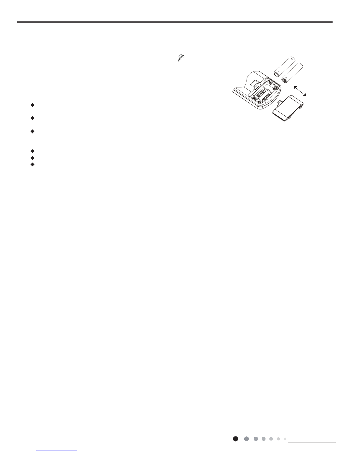
1. Press the back side of remote controller on the spot marked with
, and then
push out the cover of battery box along the arrow direction.
2. Replace two No.7 (AAA
1.5V) dry batteries and make sure the positions of + and --
polar are correct
.
3. Reinstall the cover of battery box.
Note:
During operation, point the signal sender of the remote controller at the receiving
window of the indoor unit;
The distance between signal sender and receiving window should be within 8m.
There should be no obstacle between them.
Signal may be interfered easily in the room where there is fl uorescent lamp
or wireless telephone; Remote controller should be close to indoor unit during
operation.
Replace new batteries of the same model when replacement is required.
If you don't use remote controller for a long time, please take out the batteries.
If the display on remote controller is fuzzy or if there's no display, please replace
batteries.
battery
cover of battery box
remove
reinstall
Replacement of Batteries in Remote Controller

Service Manual
Installation and Maintenance
13
6.3 Function Introduction
Ⅰ
Basic functions:
一、
Cooling mode
1. Working condition and process for cooling:
a.When Tinner amb. ≥Tpreset, the unit operates under cooling mode. Meanwhile, the fan and the compressor operate, and the fan operates at set fan speed;
b. When Tinner amb. ≤Tpreset-2℃, the compressor stops operation, and the fan operates at set fan speed;
c. When Tpreset-2℃<Tinner amb.<Tpreset, the unit keeps previous operation status.
d. When turning off the unit, the compressor stops operation. The fan will stop operation after operating at low fan speed for another 30s.
2. Under cooling mode, the temperature setting range is 1
6℃~30℃
. When compressor stops operation due to malfunction, the fan and
the swing fan operate at original status.
二、
Drying mode
1、Working condition and process for drying:
a. When Tinner amb.>Tpreset, the unit operates at drying mode. Meanwhile, the fan and the compressor operate, and the fan is defaulted to operate at low fan speed;
b. When Tpreset-2℃≤Tinner amb.≤Tpreset, the unit keeps the original operation status;
c. When Tinner amb.<Tpreset-2℃, compressor stops operation, and the fan is defaulted to operate at low fan speed.
d. When turning off the unit, the compressor stops operation. The fan will stop operation after operating at low fan speed for another 30s.
2、 In this mode, the temperature setting range is 16℃~30℃.
三、
Auto mode
Working condition and process for auto operation
a. When Tinner amb.≥26℃, the unit operates at cooling mode and Tpreset=25℃;
b. When T inner amb.≤ 22℃, the unit operate at fan mode and Tpreset=20℃;
c. When 22℃<Tinner amb.< 26℃, the unit keeps the original operation status;
四、
Fan mode
Under the fan mode, compressor stops operation and the fan operates at set fan speed. Temperature can’t be set by buttons on the control panel, while it can be set by remote controller.
Ⅱ
Buttons’ function
1. ON/OFF:
It used to turn on or turn off the unit.
2. Mode:
It used to switch among cooling mode, drying mode and fan mode.
3. Fan speed
:
It used to set high, medium, low or auto fan speed. The corresponding LED indicator is on (under drying mode, this button can’t be adjusted. The fan speed is the low speed).
4.+/- button:
4.1 The temperature setting range is 0~24 hours. The timer can be set in 0.5 hour increments between 1 and 10 hours; or in 1 hour increments for 10 hours above.
4.2 Under temperature setting range, each push on +/- button will increase or decrease 1℃.
5. Swing
:
Press this button to turn on swing function; press this button again to cancel swing function.
6. Timer function
6.1 Timer ON: Timer ON can be set under OFF status, and then Timer ON setting range is 0.5~24 hours. When the set time is
reached, the system will operate at the preset mode.
6.2 Timer OFF: Timer OFF can be set under ON status, and then Timer OFF setting range is 0.5~24 hours. When the set time is
reached, the system will stop operation.
7. The dual-8 nixie tube is defaulted to display ℃. The displays can switch among ℃ and ℉. Press “+”and“-”buttons simultaneously for
3s to switch them.
8. FILTER
When the fan has operated for 250hour in all, the lter indicator will be on to remind user to clean the lter. When the lter indicator is on,
press lter button to clear the accumulated operation time and the lter indicator will be off.
9. Sleeping mode
;
9.1 When the initial temperature is set at 16~23℃, after turning on the sleeping function, the temperature will increase by 1℃ every
two hours. When the temperature is increased by 3℃, the temperature will not change any more. When the unit has operated for 7
hours, the temperature will decreased by 1℃. After that, the unit will operate at this time all the time.
9.2 When the initial temperature is set at 24~27℃, after turning on the sleeping function, the temperature will increase by 1℃ every
two hours. When the temperature is increased by 2℃, the temperature will not change any more. When the unit has operated for 7
hours, the temperature will decreased by 1℃. After that, the unit will operate at this time all the time.
 Loading...