

Page 1

GREE ELECTRIC APPLIANCES,INC.OF ZHUHAI
Change for Life
Service Manual
GWC36LB-D3NNB2A
(Refrigerant R410A)
Model:
Page 2

Service Manual
Table of Contents
Part
Ⅰ
: Technical Information
.......................................................................1
1. Summary
......................................................................................................................1
2. Specications
..........................................................................................................2
2.1 Specication Sheet ...........................................................................................................2
2.2 Capacity Variation Ratio According to Temperature .........................................................4
2.3 Cooling and Heating Data Sheet in Rated Frequency .....................................................4
3. Outline Dimension Diagram
........................................................................5
3.1 Indoor Unit ........................................................................................................................5
3.2 Outdoor Unit .....................................................................................................................5
4. Refrigerant System Diagram
......................................................................6
5. Electrical Part
...........................................................................................................7
5.1 Wiring Diagram .................................................................................................................7
5.2 PCB Printed Diagram .......................................................................................................9
6. Function and Control
...................................................................................... 11
6.1 Remote Controller Introduction .....................................................................................11
6.2 Brief Description of Modes and Functions ......................................................................15
Part
Ⅱ
: Installation and Maintenance
.................................................20
7. Notes for Installation and Maintenance
..........................................20
8. Installation
................................................................................................................22
8.1 Installation Dimension Diagram ......................................................................................22
8.2 Installation Parts-checking ............................................................................................24
8.3 Selection of Installation Location ....................................................................................24
8.4 Electric Connection Requirement ...................................................................................24
8.5 Installation of Indoor Unit ................................................................................................24
8.6 Installation of Outdoor Unit .............................................................................................27
8.7 Vacuum Pumping and Leak Detection ...........................................................................28
8.8 Check after Installation and Test Operation ...................................................................28
9. Maintenance
............................................................................................................29
9.1 Error Code ......................................................................................................................29
9.2 Procedure of Troubleshooting ........................................................................................31
9.3 Maintenance Method for Normal Malfunction .................................................................36
Table of Contents
Page 3

Service Manual
10. Exploded View and Parts List
..............................................................38
10.1 Indoor Unit ....................................................................................................................38
10.2 Outdoor Unit .................................................................................................................40
11. Removal Procedure
.......................................................................................42
11.1 Removal Procedure of Indoor Unit ...............................................................................42
11.2 Removal Procedure of Outdoor Unit ............................................................................51
Appendix:
........................................................................................................................57
Appendix 1: Reference Sheet of Celsius and Fahrenheit ....................................................57
Appendix 2: Conguration of Connection Pipe .....................................................................57
Appendix 3: Pipe Expanding Method ...................................................................................58
Appendix 4: List of Resistance for Temperature Sensor ......................................................59
Table of Contents
Page 4
1
Technical Information
Service Manual
1. Summary
Part
Ⅰ
: Technical Information
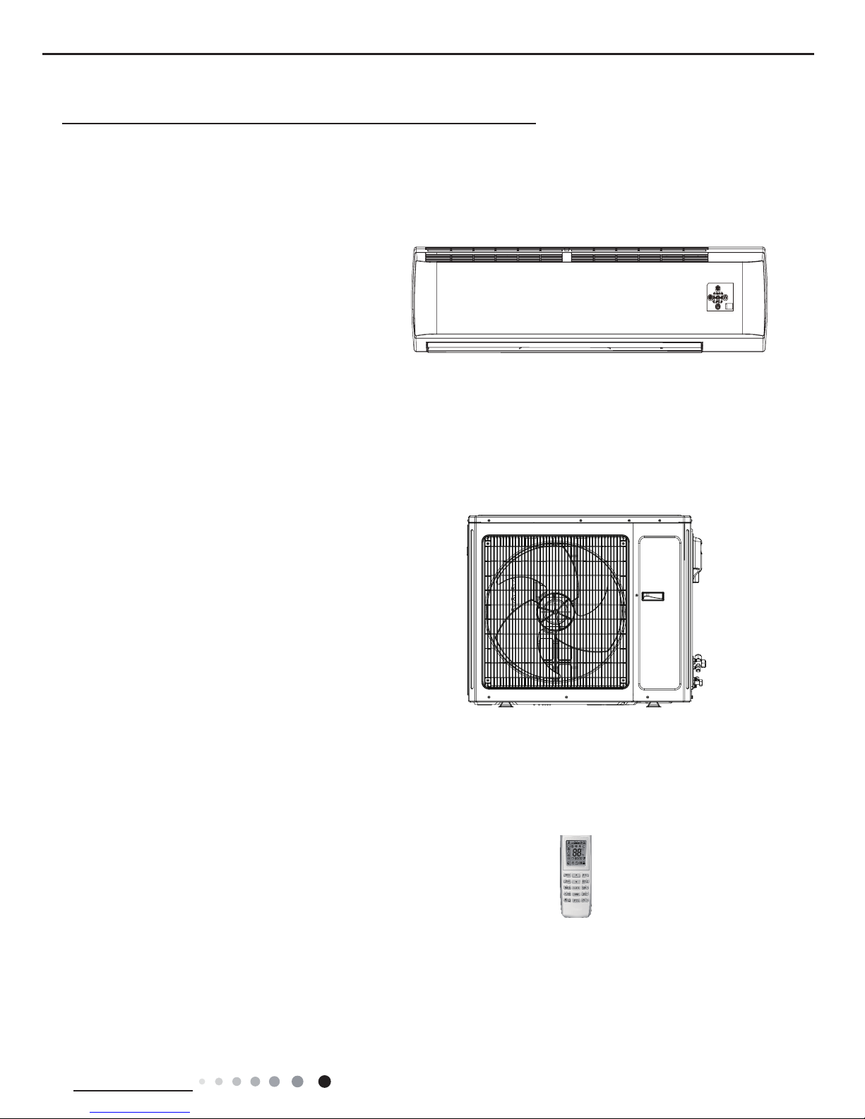
Indoor Unit:
Remote Controller:
Outdoor Unit:
GWC36LB-D3NNB2A/I
GWC36LB-D3NNB2A/O
YV1FB7
Page 5
2
Technical Information
Service Manual
2. Specications
2.1 Specication Sheet
Model GWC36LB-D3NNB2A
Product Code CA433000800
Power Supply
Rated Voltage V~ 230
Rated Frequency Hz 60
Phases 1
Power Supply Mode Outdoor
Cooling Capacity W 9670
Heating Capacity W /
Cooling Power Input W 3300
Heating Power Input W /
Cooling Power Current A 14
Heating Power Current A /
Rated Input W 4200
Rated Current A 22
Air Flow Volume(SH/H/M/L/SL) m3/h 1450/1350/1150/1000/-
Dehumidifying Volume L/h 3.5
EER W/W 2.93
COP W/W /
SEER /
HSPF /
Application Area m
2
46-70
Indoor Unit
Model of indoor unit GWC36LB-D3NNB2A/I
Indoor Unit Product Code CA433N00800
Fan Type Cross-ow
Diameter Length(DXL) mm Φ108X522.7
Fan Motor Cooling Speed (SH/H/
M/L/SL)
r/min 1450/1350/1200/1050/-
Fan Motor Heating Speed (SH/H/
M/L/SL)
r/min /
Output of Fan Motor W 60
Fan Motor RLA A 0.46
Fan Motor Capacitor μF 3
Evaporator Form Aluminum Fin-copper Tube
Pipe Diameter mm Φ7
Row-n Gap mm 2-1.5
Coil Length (LXDXW) mm 1074X25.4X381
Swing Motor Model MP24HB
Output of Swing Motor W 1.5
Fuse A 5
Sound Pressure Level (SH/H/M/L/
SL)
dB (A) 56/54/50/47/-
Sound Power Level (SH/H/M/L/SL) dB (A) 66/64/60/57/-
Dimension (WXHXD) mm 1350X326X253
Dimension of Carton Box (LXWXH) mm 1438X418X352
Dimension of Package (LXWXH) mm 1441X421X367
Net Weight kg 20
Gross Weight kg 24.5
Page 6
3
Technical Information
Service Manual
Outdoor Unit
Model of Outdoor Unit GWC36LB-D3NNB2A/O
Outdoor Unit Product Code CA433W00800
Compressor Manufacturer/Trademark
SHANGHAI HITACHI ELECTRICAL APPLIANCES
CO.;LTD.
Compressor Model ATH290RN-C9LU
Compressor Oil Mineral Oil
Compressor Type Rotary
L.R.A. A 64
Compressor RLA A 13.7
Compressor Power Input W 3020
Overload Protector UP14SE5215
Throttling Method Capillary
Operation temp ºC 16~30
Ambient temp (cooling) ºC 18~43
Ambient temp (heating) ºC /
Condenser Form Aluminum Fin-copper Tube
Pipe Diameter mm Φ7.94
Rows-n Gap mm 2.5-1.5
Coil Length (LXDXW) mm 953X57.15X748
Fan Motor Speed rpm 780
Output of Fan Motor W 90
Fan Motor RLA A 0.8
Fan Motor Capacitor μF 4
Air Flow Volume of Outdoor Unit m3/h 4000
Fan Type Axial-ow
Fan Diameter mm Φ552
Defrosting Method /
Climate Type T1
Isolation I
Moisture Protection IP24
Permissible Excessive Operating Pressure for the
Discharge Side
MPa 4.3
Permissible Excessive Operating Pressure for the
Suction Side
MPa 2.5
Sound Pressure Level (H/M/L) dB (A) 58/-/-
Sound Power Level (H/M/L) dB (A) 68/-/-
Dimension (WXHXD) mm 980X790X427
Dimension of Carton Box (LXWXH) mm 1080X485X840
Dimension of Package (LXWXH) mm 1083X488X855
Net Weight kg 68
Gross Weight kg 73
Refrigerant R410A
Refrigerant Charge kg 2.4
Connection
Pipe
Length m 5
Gas Additional Charge g/m 15
Outer Diameter Liquid Pipe mm Φ6
Outer Diameter Gas Pipe mm Φ19
Max Distance Height m 10
Max Distance Length m 30
Note:The connection pipe applies metric diameter.
The above data is subject to change without notice; please refer to the nameplate of the unit.
Page 7

4
Technical Information
Service Manual
2.3 Cooling and Heating Data Sheet in Rated Frequency
Rated cooling
condition(°C)
(DB/WB)
Model
Pressure of gas pipe
connecting indoor and
outdoor unit
Inlet and outlet pipe
temperature of heat
exchanger
Fan speed of
indoor unit
Fan speed
of outdoor
unit
Indoor Outdoor P (MPa) T1 (°C) T2 (°C)
27/19 35/24 36K 0.48 ~ 0.7 7.2 to 9.6 78.1 to 38.5 Supper High High
Instruction:
T1: Inlet and outlet pipe temperature of evaporator
T2: Inlet and outlet pipe temperature of condenser
P: Pressure at the side of big valve
Connection pipe length: 5 m.
Cooling:
2.2 Capacity Variation Ratio According to Temperature
0
20
40
60
80
100
120
Capacity ratio(%)
Outdoor temp. (°C)
-7 -5 0510
7
Conditions
Indoor:DB20°C/WB15°C
Indoor air flow:Super High
Pipe length:5m
32 33 34 35 36 37 38 39
4340 41 42
100
105
95
90
85
80
75
70
65
60
55
50
Conditions
Indoor:DB27°C/WB19°C
Indoor air flow:Super High
Pipe length:5m
Outdoor temp.(°C)
Capacity ratio (%)
Cooling:
Page 8
5
Technical Information
Service Manual
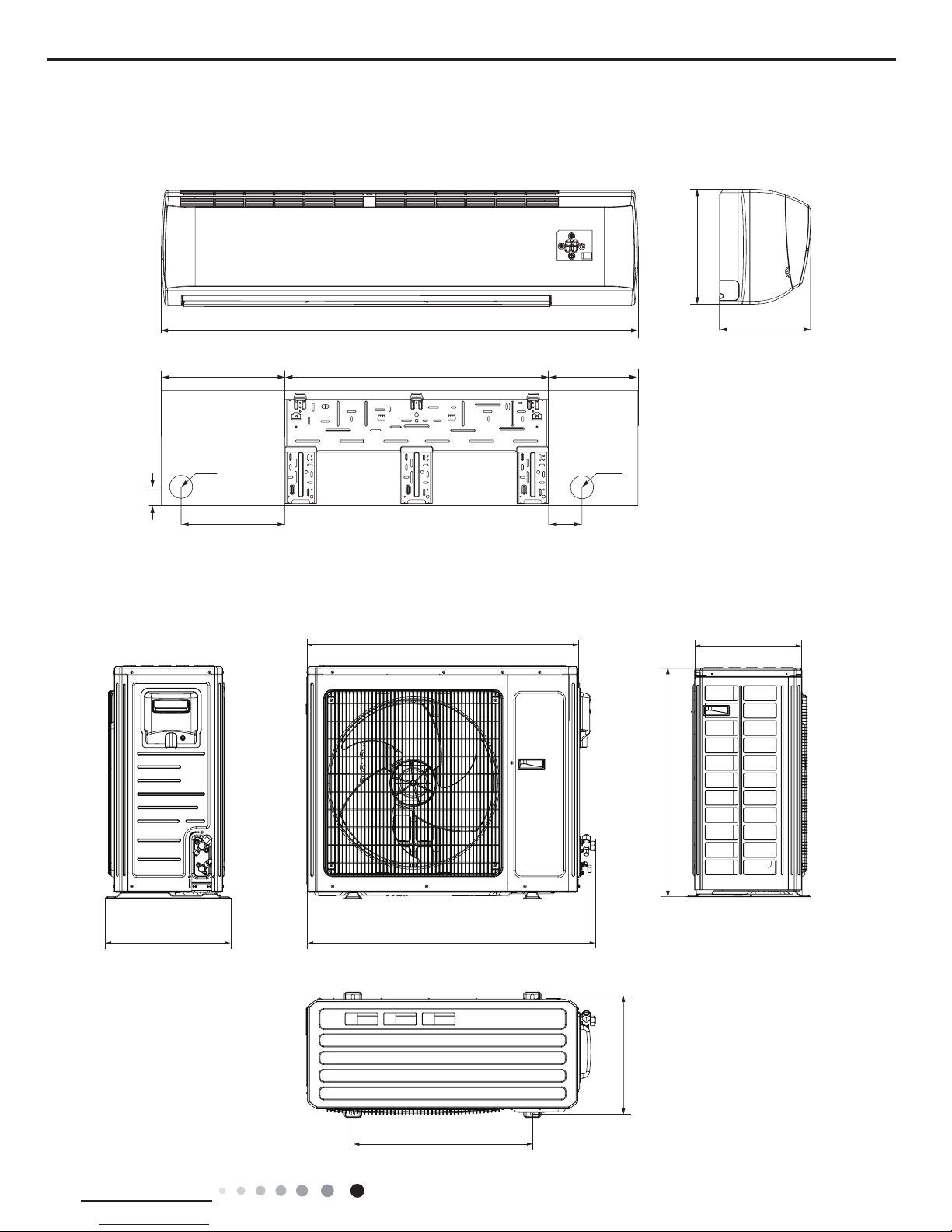
3. Outline Dimension Diagram
3.1 Indoor Unit
3.2 Outdoor Unit
Unit:mm
920
370
980427
610
395
790
1350
326
253
295
90
40
350 254746
Φ70
Φ70
Unit:mm
Page 9
6
Technical Information
Service Manual
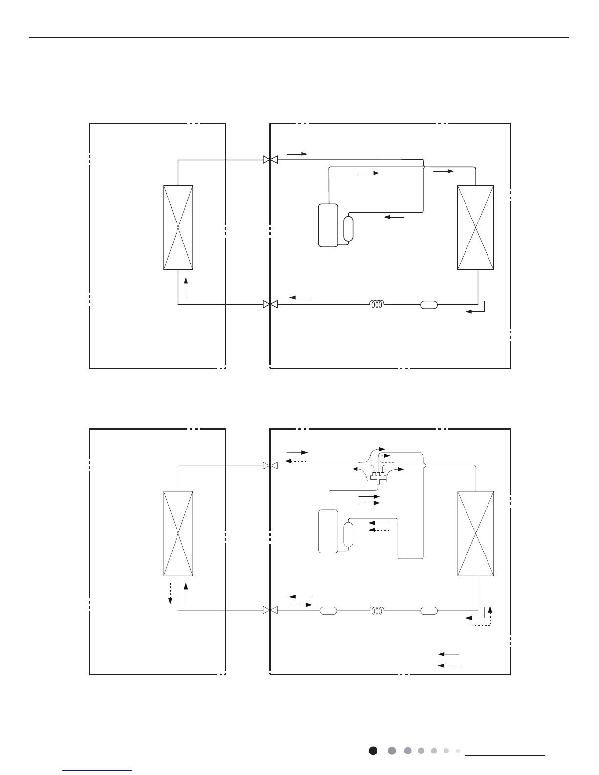
4. Refrigerant System Diagram
Refrigerant pipe diameter
Liquid :1/4" (6 mm)
Gas : 5/8" (16mm)
Indoor unit
Outdoor unit
Indoor unit
Outdoor unit
COOLING
HEATING
Accumlator
4-Way valve
Discharge
Suction
Discharge
Suction
Heat
exchanger
(evaporator)
Heat
exchanger
(evaporator)
Heat
exchanger
(condenser)
Heat
exchanger
(condenser)
Valve
Valve
Valve
Valve
Liquid pipe
side
Gas pipe
side
Liquid pipe
side
Gas pipe
side
Compressor
Accumlator
Compressor
Strainer
Strainer Strainer
Capillary
Capillary
Cooling only model
Cooling and heating model
Page 10
7
Technical Information
Service Manual
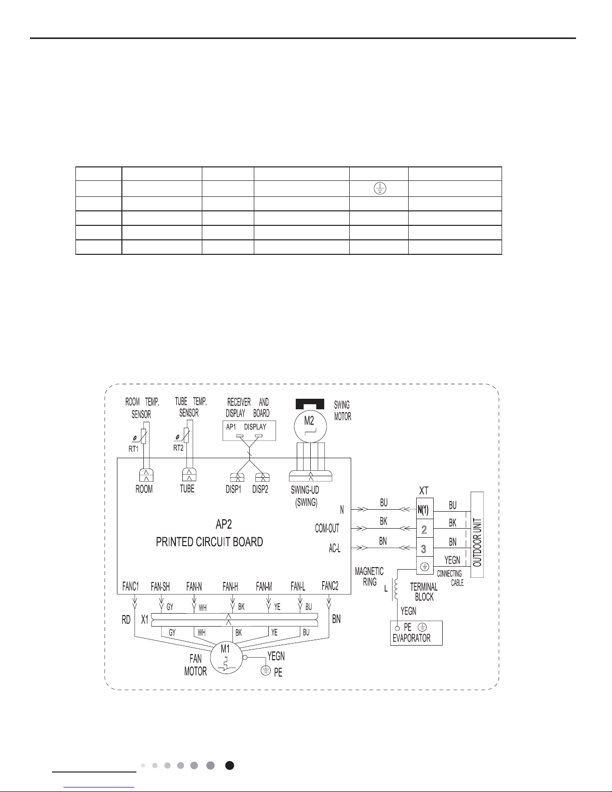
Symbol Symbol Color Symbol Symbol Color Symbol Name
WH White GN Green Grounding wire
YE Yellow BN Brown COMP Compressor
RD Red BU Blue CAP Jumper Cap
YEGN Yellow/Green BK Black / /
VT Violet OG Orange / /
5. Electrical Part
5.1 Wiring Diagram
● Indoor Unit
● Instruction
Note: Jumper cap is used to determine fan speed and the swing angle of horizontal lover for this model.
3
2
Page 11
8
Technical Information
Service Manual
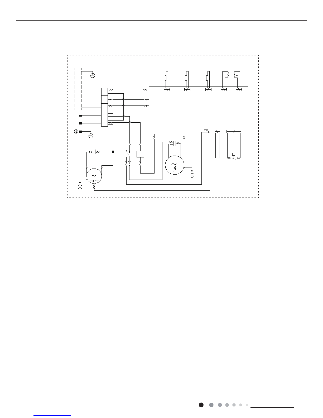
● Outdoor Unit
These circuit diagrams are subject to change without notice, please refer to the one supplied with the unit.
COM-INNER
N1
AC-L
COMP
R(M)
S
C
PE
N
YEGN
BU
BN
BK
BUW4
W6BK
BNW3
W7RD
AC CONTACTOR
BUW11
W14
AP1 PRINTED CIRCUIT BOARD
L
TERMINAL
BLOCK
ITCII
TRANSFORMER
R3R1
T-PIPE TR-OUTTR-IN
SHIELDING
RESISTOR
COMP
COMP.
PE
YEGN
W13BK
N
L
N
PE
LPP
BK(BN)
BU
YEGN
BU
W12YE
J
W5
BU
W8BU
BN
W1BN
POWER
1/L1
A2
2/T1
(6)A1(0)
W9
RESISTOR
SHIELDING
BK
C1
BN
PE
PE
YEGN
(BU)
BK
CAP.
RDBN
C2
FAN MOTOR
M
W17
SWITCH
PRESSURE
HP
P
HPP
W15W16
YE WH
HIGH
W2
OUTTUBE
SHIELDING
RESISTOR
R2
L1
XT
W10
BU
CAP.
INDOOR UNIT
OUTROOM
3
2
N(1)
(1)
KM
(4)
Page 12

9
Technical Information
Service Manual
5.2 PCB Printed Diagram
● Top view
● Bottom view
No. Name
1 Fan motor capacitor terminal
2 Live wire
3 Fuse
4 Neutral wire
5
Indoor & outdoor unit
communication cable terminal
6 Wiring terminal for turbo fan
7 Low fan level terminal
8 Medium fan level terminal
9 High fan level terminal
10
Wring terminal for neutral wire
of fan
11 Auto button
12 Up & down swing terminal
13 Ambient temp sensor
14 Tube temp sensor
15 No.2 double-8 display terminal
16 No.1 double-8 display terminal
1
2
3
456879 1110
12
13
14
15
16
Indoor Unit
Page 13

10
Technical Information
Service Manual
● Top view
● Bottom view
Outdoor Unit
1 Input of transformer
2
Terminal for outdoor fan and
compressor
3 Output of transformer
4
Terminal for high pressure
protection
5
Terminal for low pressure
protection
6
Terminal for outdoor ambient
temp sensor
7
Terminal for outdoor pipe temp
sensor
8 Current mutual-inductor
9
Terminal for communication
wire
10 Protective tube
11 Terminal for neutral wire
12 Terminal for live wire
13
Wiring terminal of outdoor
discharge temperature sensor
1 2
3
4
5
613
7
9
8
10
11
12
Page 14
11
Technical Information
Service Manual
6. Function and Control
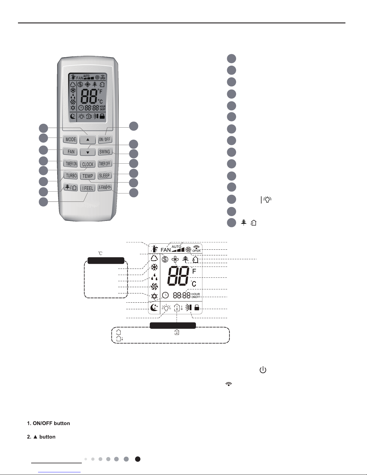
6.1 Remote Controller Introduction
Buttons on Remote Controller
Introduction for icons on display screen
1
14
3
1
13
2
2
5
4
6
7
8
11
12
13
9
14
15
ON/OFF button
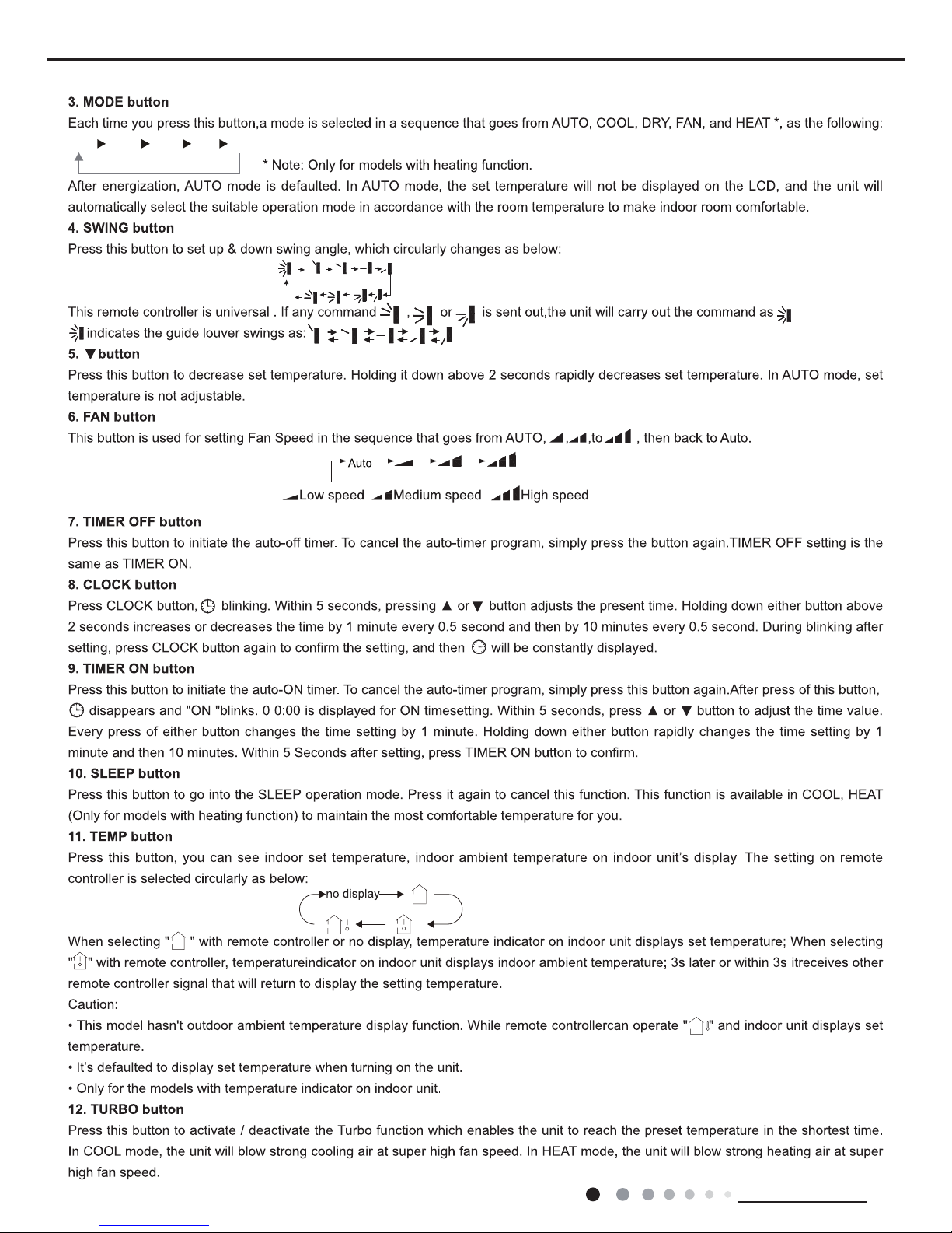
▲ button
3
FAN button
SWING button
TIMER OFF button
TURBO button
10
TEMP button
I FEEL button
button
CLOCK button
TIMER ON button
SLEEP button
Send signal
Turbo mode
8
heating function
Set temperature
Set time
TIMER ON /
TIMER OFF
Child lock
Up & down swing
Set fan speed
ventilation operation
Light
Temp. display type
:Set temp.
:Outdoor ambient temp.
:Indoor ambient temp.
Sleep mode
Clock
Heat mode
Fan mode
Dry mode
Cool mode
Auto mode
Operation mode
I feel
6
9
8
12
15
4
7
10
5
11
X-FAN button
/
MODE button
▲
button
X-fan mode
health function
Introduction for buttons on remote controller
Note:
● After putting through the power, the air conditioner will give out a sound. Operation indictor " " is ON (red indicator).
After that, you can operate the air conditioner by using remote controller.
●
Under on status, pressing the button on the remote controller, the signal icon " "
on the display of remote controller
will blink once and the air conditioner will give out a “de” sound, which means the signal has been sent to the air conditioner
.
● Under off status, set temperature and clock icon will be displayed on the display
of remote controller (If timer on, timer
off and light functions are set, the corre-
sponding icons will be displayed on the display of remote controller at the same
time); Under on status, the display will show the corresponding set function icons.
Press this button to turn on the unit. Press this button again to turn off the unit.
Press this button to increase set temperature. Holding it down above 2 seconds rapidly increases set temperature.
In AUTO mode, set temperature is not adjustable.
Page 15
12
Technical Information
Service Manual
AUTO
COOL DRY FAN
HEAT
*
OFF
Page 16

13
Technical Information
Service Manual
battery
Cover of battery box
remove
reinstall
Page 17
14
Technical Information
Service Manual
Page 18
15
Technical Information
Service Manual
6.2 Brief Description of Modes and Functions
1. Summary
(1) Buzzer
When the controller is energized or receives signal from button (emergency operation switch on air conditioner) or remote controller, the
buzzer will give out a beep.
(2) Display
After energization, all icons will be displayed once. Operation icon is in red under standby status. After turning on the unit by remote
controller, operation icon is bright and corresponding set operation mode icon will be displayed (Mode icon include: cooling, heating,
drying).
(3) Temperature parameter
◆
Indoor set temperature (Tpreset)
◆
Indoor ambient temperature (Tamb.)
◆
Inner tube temperature of indoor evaporator (Ttube)
2. Introduction of Basic Mode Function
◆
Once the compressor is energized, there should be a minimum interval of 3 mins between two start-ups.
◆
If the unit is with memory function and is off before power failure, the compressor can be restarted without an interval of 3 mins; if the
◆
unit is on before power failure, the compressor will be restarted with an interval of 3 mins.
Once compressor is started, it won’t stop within 6 mins according to the change of room temp.
(1) Auto mode
①
Operation condition and process for auto mode
Under auto mode, the system will automatically select operation mode (cooling, heating, and fan) according to indoor ambient
temperature. There swill be 30s delayed for protection between mode switchover.
◆
When Tamb. ≥26℃, the system operates under cooling mode; Ex-factory set temperature is 25℃.
◆
Cool unit: when Tamb. ≤22℃, the system operates under fan mode; Ex-factory set temperature is 25℃.
◆
Heat pump unit: when Tamb. ≤22℃, the system operates under heating mode; Ex-factory set temperature is 20℃.
◆22℃
<Tamb.<26℃: The system operates under fan mode if turn on the unit to enter into auto mode for the rst time; If switch to
auto mode from cooling, heating or fan mode, the system keeps previous operation mode; If switch to auto mode from drying mode, the
system operates under fan mode.
② Display: Operation icon, actual operation mode icon, set temperature (that’s the display content of dual-8 nixie tube)
③ Protection function is same as that under each mode.
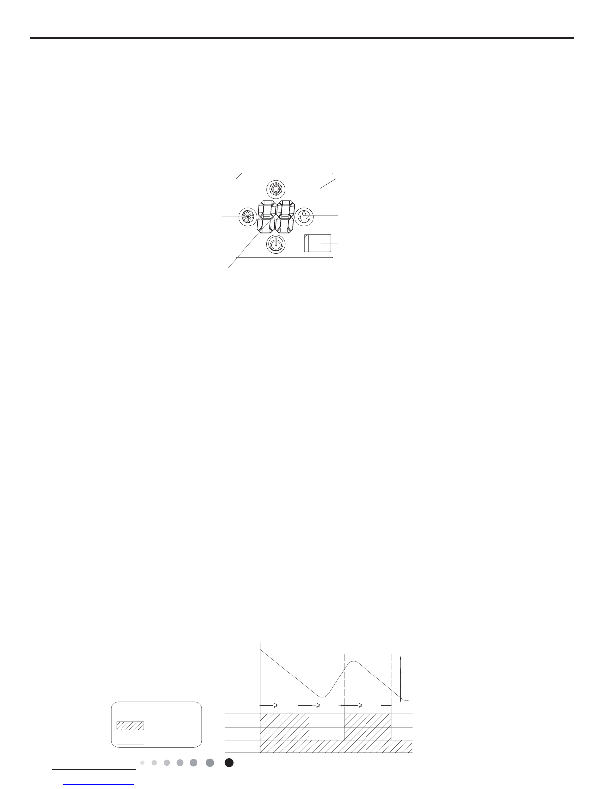
(2) Cooling mode
①
Operation condition and process for cooling mode
◆
When Tamb. ≥Tset+1℃, the system operates under cooling mode. In this case, the compressor, the ODU fan motor and the IDU fan
motor operates at set speed.
◆
When Tamb. ≤Tset-1℃, the compressor and the ODU fan motor stop, while the IDU fan motor operates at set speed.
◆
When Tset-1℃<Tamb. <Tset+1℃, the system will maintain its previous operation status.
In cooling mode, the 4-way valve is de-energized (4-way valve is not available for cooling only unit). Temperature setting range is
16~30℃.
Indicates operation
Indicates stop
Tpreset +1 ˚C
Tpreset –1 ˚C
Compressor
Outdoor fan motor
Indoor fan motor
Graphic instruction:
(Same as below)
Tamb.
Stop cooling
Start cooling
Original operating status
6 min. 3 min. 6 min.
Set fan speed
Heating icon
Drying icon
Cooling icon
Dual-8 nixie
tube display
Operation icon
Receiver
window
For B2 panel
Display
Page 19
16
Technical Information
Service Manual
②
Display: Operation icon, cooling icon, set temperature.
③
Protection function
◆
Freeze protection
During operation, when controller detected that Ttube≤0℃ for a consecutive period of time, the system enters into freeze protection. In
that case, the compressor and the ODU fan stop operation, while the IDU operates at set fan speed. If freeze protection is released and
the compressor has been out of operation for 3 mins, the unit will resume its previous operation status.
◆
Overcurrent protection ( this protection function is not available for those models whose cooling capacity ≤12000Btu/h)
During operation process, if controller detected that system current exceeds the limit value for 3s consecutively (overcurrent), only the
fan operates. About 3 mins later, if overcurrent is released, the system will resume original operation.
If overcurrent protection occurs for 6 times consecutively, and resume operation time won’t exceed 6min every time, overcurrent protection information will be displayed. After turning off the unit, display won’t be displayed.
If turn on the unit again, the system will be restated up again. Overcurrent protection information will be eliminated.
Please refer to maintenance part for display information and disposal method for details.
◆
Locked protection to IDU fan motor
During operation of IDU fan motor, if controller detected that the rotation speed of IDU fan motor less than 300/min or stop rotation, the
motor operates abnormally. In order to prevent damage to motor, controller will protect automatically, the system stops operation and
blocked information of IDU fan motor will be displayed. After turning off the unit, display won’t be displayed.
If turn on the unit again, the system will be restated up again. Blocked information of IDU fan motor will be eliminated. (For some models,
they can only be restated up after re-energized)
Please refer to maintenance part for display information and disposal method for details.
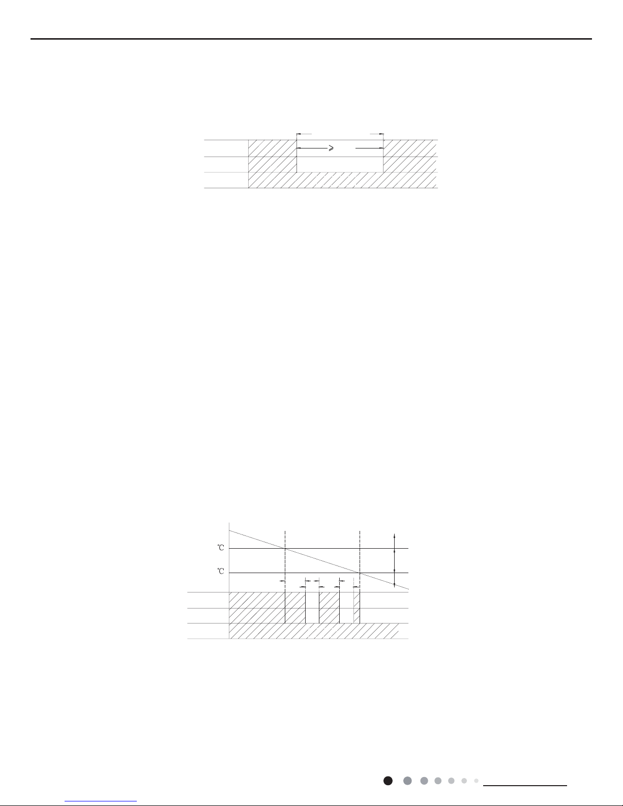
(3) Drying mode
①
Operation condition and process for drying mode
◆
When Tamb. >Tset+2℃, the system starts drying and cooling. In this case, the compressor and the ODU fan motor operate, and the
IDU fan motor operates at low speed.
◆
When Tset-2℃≤Tamb. ≤Tset+2℃, the system will start drying. In this case, the IDU fan motor operates at low speed; the compressor
and the ODU fan motor operate for 6 minutes and stop for 4 minutes in cycle.
◆
When Tamb.<Tset-2℃, the compressor and the ODU fan motor stop, while the IDU fan motor runs at low speed.
In drying mode, the 4-way valve is de-energized (4-way valve is not available for cooling only unit); Temperature setting range is
16~30℃. Fan speed can’t be adjusted.
②
Display: Operation icon, drying icon, set temperature.
③
Protection function
◆
Freeze protection
During dying and cooling operation, when the controller detected that Ttube≤0℃ for a period of time consecutively, the system will enter
into freeze protection. In that case, the compressor and the ODU fan motor stops operation, while the IDU fan motor operates at low
speed. When freeze protection is release and the compressor has stopped for 3min, the system will resume original operation.
During drying operation, when the controller detected that Ttube≤0℃ for a period of time consecutively, the system enters into freeze
protection. In that case, the compressor, the ODU fan motor stops operation, while the IDU fan motor operates at low speed. When
freeze protection is release and the compressor has stopped for 4min, the system will resume original operation.
T
preset
T
amb.
+2
T
preset-
2
Cooling
Drying
Stop
6 min.
6min.
4min.
4min.
Compressor
Low speed
Outdoor fan motor
Indoor fan motor
Freeze protection period
Compressor
Outdoor fan motor
Indoor fan motor
3 min
Set fan speed
Page 20
17
Technical Information
Service Manual
ķ
Operation condition and process for fan mode
In fan mode, the IDU fan motor operates at set speed, while the compressor and the ODU fan motor stop. 4-way valve is de-energi
zed
(4-way valve is not available for cooling only unit).
Temperature setting range is 16~30ć.
ĸ
Display: Operation icon, set temperature.
Ĺ
Protection function
In fan mode, there are overcurrent protection and blocked protection of IDU fan moto
r. Please refer to corresponding protection function
under cooling mode for details.
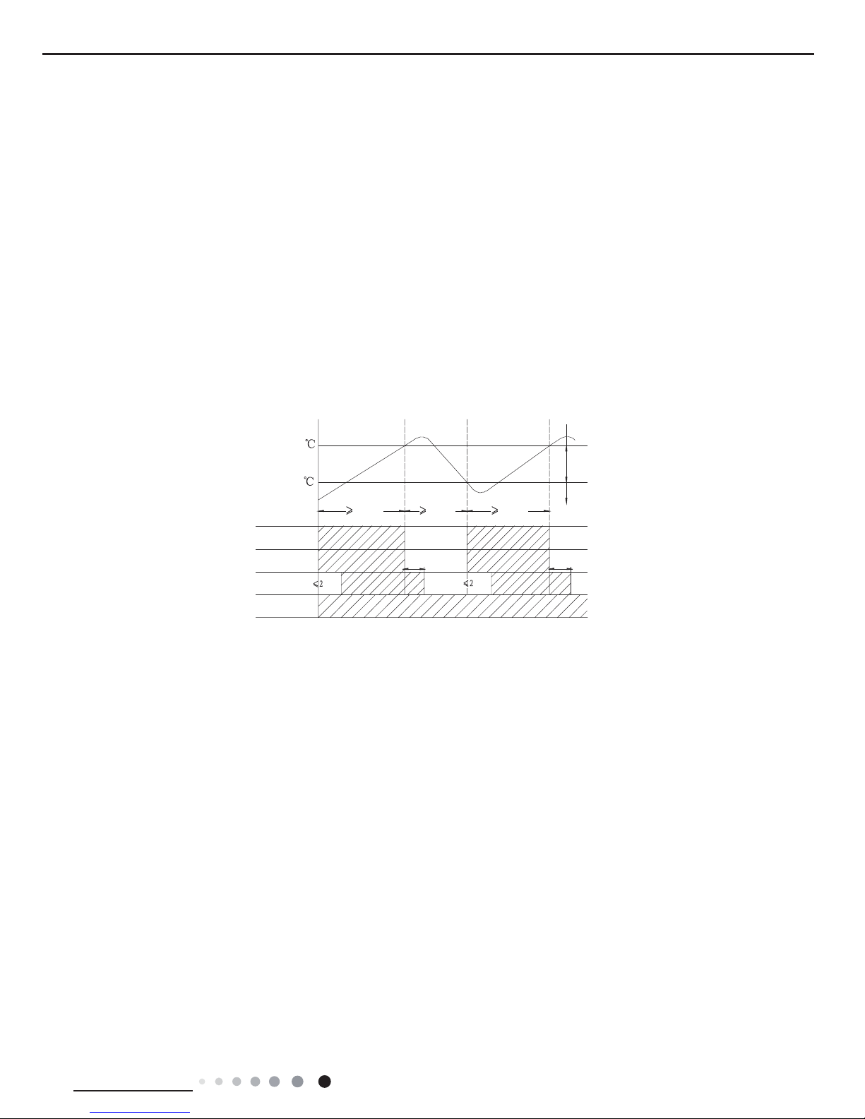
(5) Heating mode(no heating mode is not available for cooling only unit)
ķ
Operation conditioner and process for heating mode
In heating mode, 4-way valve is energized.
Temperature setting range is 16~30
ć
ĸ
Display: Operation icon, heating icon, set temperature.
Ĺ
Defrosting condition and process
For ensusing heating ef
fect, air conditioner will defrost automatically according to defrosting status on outdoor unit. During defrosting,
heating icon is bright for a while and then off for a while.
ĺ
Protection function
ƹ
Overheating prevention protection
ƹ
Noise silencing protection
When turning of
f the unit or during mode switchover, the 4-way valve is closed. In order to decrease noise, the 4-way valve will delay
2mins to be closed.
ƹ
Overcurrent protection ( this protection function is not available for those models whose cooling capacity ≤12000Btu/h)
During operation process, if controller detected that system current exceeds the limit value for 3s consecutively(overcurrent),
the
system stops operation.
About 3mins later, if overcurrent is released, the system will resume original operation. If overcurrent protection
occurs for 6 times consecutivel
y, and resume operation time won’t exceed 6min every time, overcurrent protection information will be
displayed.
After turning off the unit, display won’t be displayed.
If turn on the unit again, the system will be restated up again. Overcurrent protection information will be eliminated.
Please refer to maintenance part for display information and disposal method for details
.
ƹ
Locked protection to IDU fan motor
During operation of IDU fan moto
r, if controller detected that the rotation speed of IDU fan motor less than 300/min or stop rotation, the
motor operates abnormall
y. In order to prevent damage to motor, controller will protect automatically, the system stops operation and
blocked information of IDU fan motor will be displayed.
After turning off the unit, display won’t be displayed.
If turn on the unit again, the system will be restated up again. Blocked information of IDU fan motor will be eliminated. (For
some models, they can only be restated up after re-energized)
Please refer to maintenance part for display information and disposal method for details.
T
preset
+4
T
preset
+2
Stop heating
Original operating status
Start heating
valve
Outdoor unit
Intdoor unit
Compressor
min.
min.
T
amb
.
Set fan speedSet fan speed
Reversing
ƹ
When Tamb.-Tsupplementary≤Tset-1,ć the unit starts heating operation. In this case, the 4-way valve is energized; the compressor
and ODU fan motor run simultaneously; the IDU fan motor runs after a
while to prevent blowing out cold air.
ƹ
When Tamb.-Tsupplementary≥Tset+1ć, the compressor and ODU fan motor stop; the 4-way valve remains energized; the IDU fan
motor blow
s residual heat for a while at set speed to prevent high temperature inside the unit.
ƹ
When Tset-1ć˘Tamb.-Tsupplementary˘Tset+1ć, the unit will maintain its previous running status.
During operation, if Ttube≥55ć is detected by the controller, the ODU fan motor stops operation; When Ttube returns to normal, the
ODU fan motor resumes operation.
(4) Fan mode
◆
Other protection is same as that under cooling mode.
6 min. 6 min.3 min.
60S 60S
Page 21

18
Technical Information
Service Manual
3. Other Control Function Introduction
(1)Timer function
Controller has general timer function and clock timer function. When you select the remote controller with general timer function, only
the general timer function of controller can be activated; when you select the remote controller with clock timer, only the clock timer
function of controller can be activated.
①
General timer: The precision of general timer is 0.5hour. 24hours circulated timer can’t be set.
◆
Timer ON: Timer ON can be set at unit OFF. If selected ON time is reached, the unit will start to operate according to previous
setting status. Time setting range is 0.5~24hr in 30-minute increments.
◆
Timer OFF: Timer OFF can be set at unit ON. If selected OFF time is reached, the unit will stop. Time setting range is 0.5~24hr in
30-minute increments.
②
Clock timer: The precision of clock timer is 1 minute. 24hours circulated timer can be set.
◆
Timer ON: If timer ON is set during operation of the unit, the unit will continue to operate. If timer ON is set at unit OFF, upon ON
time reaches, the unit will start to run according to previous setting status.
◆
Timer OFF: If timer OFF is set at unit OFF, the system will keep standby status. If timer OFF is set at unit ON, upon OFF time
reaches, the unit will stop operation.
◆
Timer change:
Although timer has been set, the unit still can be turned on/off by pressing ON/OFF button on the remote controller. You can also reset
the timer.
If timer ON and timer OFF are set at the same time during operation of the unit, the unit will keep running at current status till OFF
time reaches. Upon ON time reached, the system will be turned on automatically. The unit will operate circularly like that every
24hours.
If timer ON and timer OFF are set at unit OFF status, the system keep OFF status till ON time reaches. Upon OFF time reaches, the
system will be turned OFF automatically. The unit will operate circularly like that every 24hours.
(2) Emergency operation switch
After pressing this button, the system will operate according under auto mode and the IDU fan motor operates at auto speed. Swing
motor operates when the IDU fan motor operates. Press this button again to turn off the unit.
(3) Sleep function
In this mode, the system will select proper sleep curve to operate according to different set temperature.
①
If start up sleep function under cooling or drying mode, the system will increase set temperature automatically within a certain
range to operate.
②
If start up sleep function under heating mode, the system will decrease set temperature automatically within a certain range to
operate.
(4) Turbo function
Turbo function can be set under cooling and heating modes. During operation of turbo function, the system operates at the maximum
fan speed.
(5) Dry function
Dry function can be set under cooling and drying modes. During operation of drying function, the fan will stop operation after operating
for a period of time when turning off the unit.
(6) Auto fan speed control
Auto fan speed control can be set under cooling, heating and fan mode. During operation of auto fan speed control, the IDU fan motor
will adjust the fan speed (high, medium or low speed) according to ambient temperature.
(7) Up&down swing control
①
After energization, up & down swing motor will rstly have the horizontal louver rotate anticlockwise to position O to close air outlet.
If swing function has not been set after start-up of the unit, horizontal louver will turn clockwise to position D in heating mode, or turn
clockwise to level position L in other modes.
②
If swing function is set when turning on the unit, the horizontal louver will swing between L and D.
Horizontal louver has 7 swing statuses:
◆
Stay at position L: control by remote controller:
◆
Stay at position A: control by remote controller:
◆
Stay at position B: control by remote controller:
◆
Stay at position C: control by remote controller:
◆
Stay at position D: control by remote controller:
◆
Swing between L and D: control by remote controller: , , ,
◆
Stop at any postion between L and D (angles between L and D are equiangular) and no display
on remote controller.
O(0°)
Emergency
operation switch
Press
Press
ON status(Auto mode)
OFF status
Page 22

19
Technical Information
Service Manual
③
When turning off the unit, horizontal louver will close at position O.
④
Swing action is valid only when set swing command and the IDU fan motor is operating.
(8) Dual-8 nixie tube display
◆
When the air conditioner is turned on for the rst time, dual-8 nixie tube defaulted to display current set temperature.
◆
When controller receives signal of display set temperature, dual-8 nixie tube displays set temperature. When received remote control
signal is switched to indoor ambient temperature display status signal from other display status, dual-8 nixie tube will display indoor
ambient temperature for 3-5s, and then turn back to display set temperature. If remote control to set other status, the display keeps the
same.
◆
When air conditioner has a malfunction,dual-8 nixie tube will show relevant error code.
◆
Heating icon is bright for a period time and then OFF for some models.
◆
If turn off light button, all display will be turned off.
(9) Memory function
①
Power failure when turning on the unit
◆
Memory content: ON status, mode, up&down swing, light, set temperature, set fan speed, general timer, Fahrenheit/ Celsius
◆
General timer can be memorized. Time of timer is calculated again from energization.
◆
Clock timer can’t be memorized.
②
Power failure when turning off the unit
◆
Memory content: OFF status, mode, up&down swing, light, set temperature, set fan speed, general timer, Fahrenheit/ Celsius
◆
General timer can be memorized. Time of timer is calculated again from energization.
◆
Clock timer can’t be memorized.
4. Special Function
(1) Health function (for the model with health function)
During operation of the IDU fan motor, press health button on the remote controller to start health function (If there is not health button on
the remote controller, the unit defaults health function ON).
(2) I Feel function (for all models, but it needs the remote controller which can set this function)
When I FEEL command is received, the controller will operate according to the ambient temperature sent by the remote controller (For
defrosting and cold air prevention, the unit operates according to the ambient temperature sensed by the air conditioner). The remote
controller will regularly send ambient temperature data to the controller. When the data has not been received for a long time, the unit
will operate according to the temperature sensed by the air conditioner. If I FEEL function is not set, the ambient temperature will be that
sensed by the air conditioner.
F1 Indoor ambient temperature sensor is open/short-circuited
F2 Indoor evaporator temperature sensor is open/short-circuited
F3 Outdoor ambient temperature sensor is open/short-circuited
F4 Outdoor condenser temperature sensor is open/short-circuited
F5 Outdoor discharge temperature sensor is open/short-circuited
E1 High pressure protection
E4 High discharge temperature protection of compressor
E5 Overcurrent protection
E6 Communication malfunction
Page 23

20
Installation and Maintenance
Service Manual
1. Select the installation location according to the requirement of this manual.(See the requirements in installation
part)
2. Handle unit transportation with care; the unit should not
be carried by only one person if it is more than 20kg.
3. When installing the indoor unit and outdoor unit, a sufcient xing bolt must be installed; make sure the installation
support is rm.
4. Ware safety belt if the height of working is above 2m.
5. Use equipped components or appointed components during installation.
6. Make sure no foreign objects are left in the unit after nishing installation.
Electrical Safety Precautions:
7. Notes for Installation and Maintenance
Safety Precautions:
Important!
Please read the safety precautions carefully before
installation and maintenance.
The following contents are very important for installation
and maintenance.
Please follow the instructions below.
●The installation or maintenance must accord with the
instructions.
●Comply with all national electrical codes and local
electrical codes.
●Pay attention to the warnings and cautions in this
manual.
●All installation and maintenance shall be performed by
distributor or qualied person.
●All electric work must be performed by a licensed
technician according to local regulations and the
instructions given in this manual.
●Be caution during installation and maintenance. Prohibit
incorrect operation to prevent electric shock, casualty and
other accidents.
1. Cut off the power supply of air conditioner before
checking and maintenance.
2. The air condition must apply specialized circuit and
prohibit share the same circuit with other appliances.
3. The air conditioner should be installed in suitable
location and ensure the power plug is touchable.
4. Make sure each wiring terminal is connected firmly
during installation and maintenance.
5. Have the unit adequately grounded. The grounding
wire can’t be used for other purposes.
6. Must apply protective accessories such as protective
boards, cable-cross loop and wire clip.
7. The live wire, neutral wire and grounding wire of
power supply must be corresponding to the live wire,
neutral wire and grounding wire of the air conditioner.
8. The power cord and power connection wires can’t be
pressed by hard objects.
9. If power cord or connection wire is broken, it must be
replaced by a qualied person.
1. Avoid contact between refrigerant and re as it generates
poisonous gas; Prohibit prolong the connection pipe by
welding.
2. Apply specied refrigerant only. Never have it mixed with
any other refrigerant. Never have air remain in the refrigerant
line as it may lead to rupture or other hazards.
3. Make sure no refrigerant gas is leaking out when
installation is completed.
4. If there is refrigerant leakage, please take sufficient
measure to minimize the density of refrigerant.
5. Never touch the refrigerant piping or compressor without
wearing glove to avoid scald or frostbite.
Warnings
Refrigerant Safety Precautions:
Improper installation may lead to re hazard, explosion,
electric shock or injury.
Installation Safety Precautions:
Part
Ⅱ
: Installation and Maintenance
10. If the power cord or connection wire is not long enough,
please get the specialized power cord or connection wire
from the manufacture or distributor. Prohibit prolong the wire
by yourself.
11. For the air conditioner without plug, an air switch must
be installed in the circuit. The air switch should be all-pole
parting and the contact parting distance should be more than
3mm.
12. Make sure all wires and pipes are connected properly and
the valves are opened before energizing.
13. Check if there is electric leakage on the unit body. If yes,
please eliminate the electric leakage.
14. Replace the fuse with a new one of the same specication
if it is burnt down; don’t replace it with a cooper wire or
conducting wire.
15. If the unit is to be installed in a humid place, the circuit
breaker must be installed.
Page 24

21
Installation and Maintenance
Service Manual
Main Tools for Installation and Maintenance
1. Level meter, measuring tape
4. Electroprobe
7. Electronic leakage detector
10. Pipe pliers, pipe cutter
2. Screw driver
5. Universal meter
8. Vacuum pump
11. Pipe expander, pipe bender
3. Impact drill, drill head, electric drill
6. Torque wrench, open-end wrench, inner
hexagon spanner
9. Pressure meter
12. Soldering appliance, refrigerant container
Page 25

22
Installation and Maintenance
Service Manual
8. Installation
8.1 Installation Dimension Diagram
Space to the ceiling
Space to the wall
At least 15cm
At least 15cm
At least 15cm
At least 250cm
Space to the wall
Space to the obstruction
roolf eht ot ecapS
Space to the obstruction
Drainage pipe
Space to the wall
Space to the obstruction
Space to the obstructio
Space to the obstruction
At least 300cm
At least 50cm
At least 200cm
At least 30cm
At least 30cm
At least 50cm
Page 26

23
Installation and Maintenance
Service Manual
Preparation before installation
Prepare tools
Read the requirements
for electric connection
select installation
location
Select indoor unit
installation location
Install wall-mounting
frame, drill wall holes
Connect pipes of indoor
unit and drainage pipe
Connect wires of indoor unit
Connect wires of outdoor unit
Bind up pipes and
hang the indoor unit
Make the bound pipes pass
through the wall hole and then
connect outdoor unit
Neaten the pipes
Vacuum pumping and leakage detection
Check after installation and test operation
Finish installation
Note: this flow is only for reference; please find the more detailed installation steps in this section
.
Select outdoor unit
installation location
Install the support of outdoor unit
(select it according to the actual situation)
Install drainage joint of outdoor unit
(only for cooling and heating unit)
Connect pipes of outdoor unit
Start installation
Fix outdoor unit
Installation procedures
Page 27

24
Installation and Maintenance
Service Manual
No. Name No. Name
1 Indoor unit 8 Sealing gum
2 Outdoor unit 9 Wrapping tape
3 Connection pipe 10
Support of outdoor
unit
4 Drainage pipe 11 Fixing screw
5
Wall-mounting
frame
12
Drainage plug(cooling
and heating unit)
6
Connecting
cable(power cord)
13
Owner’s manual,
remote controller
7 Wall pipe
1. Safety Precaution
(1) Must follow the electric safety regulations when installing
the unit.
(2) According to the local safety regulations, use qualified
power supply circuit and air switch.
(3) Make sure the power supply matches with the requirement
of air conditioner. Unstable power supply or incorrect wiring
may result in electric shock,re hazard or malfunction. Please
install proper power supply cables before using the air
conditioner.
(4) Properly connect the live wire, neutral wire and grounding
wire of power socket.
(5) Be sure to cut off the power supply before proceeding any
work related to electricity and safety.
(6) Do not put through the power before nishing installation.
(7) For appliances with type Y attachment,the instructions
shall contain the substance of thefollowing.If the supply cord is
damaged,it must be replaced by the manufacturer,its service
agent or similarly qualied persons in order to avoid a hazard.
(8) The temperature of refrigerant circuit will be high, please
keep the interconnection cable away from the copper tube.
8.2 Installation Parts-checking
8.3 Selection of Installation Location
8.4 Electric Connection Requirement
8.5 Installation of Indoor Unit
Air-conditioner Air switch capacity
36K 32A
1.Please contact the local agent for installation.
2.Don't use unqualied power cord.
1. Basic Requirement:
Installing the unit in the following places may cause
malfunction. If it is unavoidable, please consult the local dealer:
(1) The place with strong heat sources, vapors, ammable or
explosive gas, or volatile objects spread in the air.
(2) The place with high-frequency devices (such as welding
machine, medical equipment).
(3) The place near coast area.
(4) The place with oil or fumes in the air.
(5) The place with sulfureted gas.
(6) Other places with special circumstances.
2. Grounding Requirement:
(1) The air conditioner is rst class electric appliance. It must
be properly grounding with specialized grounding device
by a professional. Please make sure it is always grounded
effectively, otherwise it may cause electric shock.
(2) The yellow-green wire in air conditioner is grounding wire,
which can't be used for other purposes.
(3) The grounding resistance should comply with national
electric safety regulations.
(4) The appliance must be positioned so that the plug is
accessible.
(5) An all-pole disconnection switch having a contact separation
of at least 3mm in all poles should be connected in xed wiring.
(6) Including an air switch with suitable capacity, please note
the following table. Air switch should be included magnet
buckle and heating buckle function, it can protect the circuitshort and overload. (Caution: please do not use the fuse only
for protect the circuit)
1. Choosing Installation Iocation
Recommend the installation location to the client and then
conrm it with the client.
2. Install Wall-mounting Frame
(1) Hang the wall-mounting frame on the wall; adjust it in
horizontal position with the level meter and then point out the
screw xing holes on the wall.
(2) Drill the screw xing holes on the wall with impact drill (the
specification of drill head should be the same as the plastic
expansion particle) and then ll the plastic expansion particles
2. Indoor Unit:
(1) There should be no obstruction near air inlet and air outlet.
(2) Select a location where the condensation water can be
dispersed easily and won't affect other people.
(3) Select a location which is convenient to connect the
outdoor unit and near the power socket.
(4) Select a location which is out of reach for children.
(5) The location should be able to withstand the weight of
indoor unit and won't increase noise and vibration.
(6) The appliance must be installed 2.5m above oor.
(7) Don't install the indoor unit right above the electric
appliance.
(8) The appliance shall not be installed in the laundry.
3. Outdoor Unit:
(1) Select a location where the noise and outow air emitted by
the outdoor unit will not affect neighborhood.
(2) The location should be well ventilated and dry, in which the
outdoor unit won't be exposed directly to sunlight or strong
wind.
(3) The location should be able to withstand the weight of
outdoor unit.
(4) Make sure that the installation follows the requirement of
installation dimension diagram.
(5) Select a location which is out of reach for children and far
away from animals or plants.If it is unavoidable, please add
fence for safety purpose.
Note:
Page 28

25
Installation and Maintenance
Service Manual
Wall
Wall
Mark on the middle of it
Gradienter
Left
Right
(Rear piping hole)
(Rear piping hole)
Space
to the
wall
above
Space
to the
wall
above
Ф
70mm
Ф
70mm
Outlet
pipe
Drain hose
Drain hose
Tape
Outlet pipe
Insulating pip
e
Torque wrenc
h
Open-end
wrench
Indoor pipe
Pipe
Union nut
Union nutPipe joint
Pipe
Hex nut diameter(mm) Tightening torque(N.m)
Φ6 15~20
Φ9.52 30~40
Φ12 45~55
Φ16 60~65
Φ19 70~75
Refer to the following table for wrench moment of force
:
Left
Rear lef
t
Right
Rear right
Drain hose
Insulating pip
e
5-10
°
Φ70m
m
Indoor
Outdoor
(1) Pay attention to dust prevention and take relevant safety
measures when opening the hole.
(2) The plastic expansion particles are not provided and should
be bought locally.
(1) Add insulating pipe in the indoor drain hose in order to
prevent condensation.
(2) The plastic expansion particles are not provided.
(As show in Fig.10)
Fig.1
Fig.2
Fig.5 Fig.6
Fig.7
Fig.8
Fig.9
Fig.10
Fig.3
Fig.4
in the holes.
(3) Fix the wall-mounting frame on the wall with tapping screws
(ST4.2X25TA) and then check if the frame is rmly installed by
pulling the frame. If the plastic expansion particle is loose,
please drill another xing hole nearby.
3. Install Wall-mounting Frame
(1) Choose the position of piping hole according to the direction
of outlet pipe. The position of piping hole should be a little
lower than the wall-mounted frame.(As show in Fig.1)
5. Connect the Pipe of Indoor Unit
(1) Aim the pipe joint at the corresponding bellmouth.(As show
in Fig.5)
(2) Pretightening the union nut with hand.
(3) Adjust the torque force by referring to the following sheet.
Place the open-end wrench on the pipe joint and place the
torque wrench on the union nut. Tighten the union nut with
torque wrench.(As show in Fig.6)
(4) Wrap the indoor pipe and joint of connection pipe with
insulating pipe, and then wrap it with tape.(As show in Fig.7)
6. Install Drain Hose
(1) Connect the drain hose to the outlet pipe of indoor unit.(As
show in Fig.8)
(2) Bind the joint with tape.(As show in Fig.9)
4. Outlet Pipe
(1) The pipe can be led out in the direction of right, rear right,
left or rear left.(As show in Fig.3)
(2) When selecting leading out the pipe from left or right, please
cut off the corresponding hole on the bottom case.(As show in
Fig.4)
(2) Open a piping hole with the diameter of Φ70 on the selected
outlet pipe position.In order to drain smoothly, slant the piping
hole on the wall slightly downward to the outdoor side with the
gradient of 5-10°.(As show in Fig.2)
Note:
Note:
Cut off
the hole
Left Right
Page 29

26
Installation and Maintenance
Service Manual
Wiring cove
r
Screw
Panel
(4) Put wiring cover back and then tighten the screw.
(5) Close the panel.
Indoor unit
Gas
pipe
Indoor and
outdoor power cord
Liquid
pipe
Drain hose
Band
Drain hose
Band
Connection pipe
Indoor power cord
(1) All wires of indoor unit and outdoor unit should be
connected by a professional.
(2) If the length of power connection wire is insufcient, please
contact the supplier for a new one. Avoid extending the wire by
yourself.
(3) For the air conditioner with plug, the plug should be
reachable after nishing installation.
(4) For the air conditioner without plug, an air switch must be
installed in the line. The air switch should be all-pole parting
and the contact parting distance should be more than 3mm.
(1) The power cord and control wire can't be crossed or
winding.
(2) The drain hose should be bound at the bottom.
Do not bend the drain hose too excessively in order to prevent
blocking.
7. Connect Wire of Indoor Unit
(1) Open the panel, remove the screw on the wiring cover and
then take down the cover.(As show in Fig.11)
8. Bind up Pipe
(1) Bind up the connection pipe, power cordand drain hose with
the band.(As show in Fig.14)
(2) Reserve a certain length of drain hose and power cord
for installation when binding them. When binding to a certain
degree, separate the indoor power and then separate the drain
hose.(As show in Fig.15)
(3) Bind them evenly.
(4) The liquid pipe and gas pipe should be bound separately at
the end.
9. Hang the Indoor Unit
(1) Put the bound pipes in the wall pipe and then make them
pass through the wall hole.
(2) Hang the indoor unit on the wall-mounting frame.
(3) Stuff the gap between pipes and wall hole with sealing gum.
(4) Fix the wall pipe.(As show in Fig.16)
(5) Check if the indoor unit is installed rmly and closed to the
wall.(As show in Fig.17)
(2) Make the power connection wire go through the cable-cross
hole at the back of indoor unit and then pull it out from the front
side.(As show in Fig.12)
(3) Remove the wire clip; connect the power connection wire
to the wiring terminal according to the color; tighten the screw
and then x the power connection wire with wire clip.(As show
in Fig.13)
Note:
Note:
Note:
Indoor
Outdoor
Wall pipe
Sealing gum
Upper hook
Lower hook of
wall-mounting fram
e
Fig.11
Fig.12
Fig.13
Fig.14
Fig.15
Fig.16
Fig.17
Power connection
wire
Cable-cross
hole
Note: The wiring connect is for reference only,
please refer to the actual one
.
Wire clip
Wiring board
Grounding
wire
Connect to outdoor unit
brown
yellow-
green
N(1)
black
blue
2 3
Page 30

27
Installation and Maintenance
Service Manual
(1) Take sufficient protective measures when installing the
outdoor unit.
(2) Make sure the support can withstand at least four times the
unit weight.
(3) The outdoor unit should be installed at least 3cm above the
oor in order to install drain joint.(As show in Fig.18)
(4) For the unit with cooling capacity of 2300W~5000W, 6
expansion screws are needed; for the unit with cooling capacity
of 6000W~8000W, 8 expansion screws are needed; for the
unit with cooling capacity of 10000W~16000W, 10 expansion
screws are needed.
(1) After tightening the screw, pull the power cord slightly to
check if it is rm.
(2) Never cut the power connection wire to prolong or shorten
the distance.
(1) The through-wall height of drain hose shouldn't be higher
than the outlet pipe hole of indoor unit.(As show in Fig.25)
(2) Slant the drain hose slightly downwards. The drain hose
can't be curved, raised and uctuant, etc.(As show in Fig.26)
Note:
Note:
Note:
The drain hos
can't raise
upwards
gas pipe
Liquid pipe
Liquid
valve
gas valve
Union nut
Pipe joint
Foot holes
Foot holes
8.6 Installation of Outdoor Unit
1. Fix the Dupport of Outdoor Unit(select it according to
the actual installation situation)
(1) Select installation location according to the house structure.
(2) Fix the support of outdoor unit on the selected location with
expansion screws.
5. Connect Outdoor Electric Wire
(1) Remove the wire clip; connect the power connection wire
and power cord to the wiring terminal according to the color; x
them with screws.(As show in Fig.23)
6. Neaten the Pipes
(1) The pipes should be placed along the wall, bent reasonably
and hidden possibly. Min. semidiameter of bending the pipe is
10cm.
(2) If the outdoor unit is higher than the wall hole, you must set
a U-shaped curve in the pipe before pipe goes into the room,
in order to prevent rain from getting into the room.(As show in
Fig.24)
(2) Fix the power connection wire and power cord with wire clip.
2. Install Drain Joint(Only for cooling and heating unit)
(1) Connect the outdoor drain joint into the hole on the chassis.
(2) Connect the drain hose into the drain vent.
(As show in Fig.19)
3. Fix Outdoor Unit
(1) Place the outdoor unit on the support.
(2) Fix the foot holes of outdoor unit with bolts.
(As show in Fig.20)
4. Connect Indoor and Outdoor Pipes
(1) Remove the screw on the right handle of outdoor unit and
then remove the handle.(As show in Fig.21)
(2) Remove the screw cap of valve and aim the pipe joint at the
bellmouth of pipe.(As show in Fig.22)
(3) Pretightening the union nut with hand.
(4) Tighten the union nut with torque wrench .
Hex nut diameter(mm) Tightening torque(N.m)
Φ6 15~20
Φ9.52 30~40
Φ12 45~55
Φ16 60~65
Φ19 70~75
Refer to the following table for wrench moment of force
:
Fig.18 Fig.19
Fig.20
Fig.22
Fig.21
Fig.23
Fig.24
Fig.25
Chassis
Outdoor drain join
t
Drain hose
Drain vent
U-shaped curve
Wall
Drain hose
A
t least 3cm above the floo
r
handle
Note: the wiring connect is for reference only,
please refer to the actual one
.
Power connection wire
Power cord
LN
LN
Blue BlueYEGN YEGNBlack
Black
(Brown)
Brown
BU BK BUBNBNYEGN
YEGN
3N2
N(1)
L
L
N
Power
Handle
Page 31

28
Installation and Maintenance
Service Manual
(3) The water outlet can't be placed in water in order to drain
smoothly.(As show in Fig.27
Liquid valve
Gas valve
Refrigerant charging
vent
Nut of refrigerant
Charging vent
Vacuum pump
Piezometer
Valve cap
Lo Hi
Inner hexagon
spanner
Open
Close
The drain hose can't be fluctuant
The drain hose
can't be fluctuant
The water
outlet can't be
fluctuant
NO. Items to be checked Possible malfunction
1
Has the unit been
installed rmly?
The unit may drop, shake or
emit noise.
2
Have you done the
refrigerant leakage test?
It may cause insufcient cooling
(heating) capacity.
3
Is heat insulation of
pipeline sufcient?
It may cause condensation and
water dripping.
4 Is water drained well?
It may cause condensation and
water dripping.
5
Is the voltage of power
supply according to the
voltage marked on the
nameplate?
It may cause malfunction or
damage the parts.
6
Is electric wiring and
pipeline installed
correctly?
It may cause malfunction or
damage the parts.
7
Is the unit grounded
securely?
It may cause electric leakage.
8
Does the power cord
follow the specication?
It may cause malfunction or
damage the parts.
9
Is there any obstruction
in air inlet and air outlet?
It may cause insufcient cooling
(heating).
10
The dust and
sundries caused
during installation are
removed?
It may cause malfunction or
damaging the parts.
11
The gas valve and liquid
valve of connection pipe
are open completely?
It may cause insufcient cooling
(heating) capacity.
The water outlet
can't be placed
in water
1. Use Vacuum Pump
(1) Remove the valve caps on the liquid valve and gas valve
and the nut of refrigerant charging vent.
(2) Connect the charging hose of piezometer to the refrigerant
charging vent of gas valve and then connect the other charging
hose to the vacuum pump.
(3) Open the piezometer completely and operate for 10-15min
to check if the pressure of piezometer remains in -0.1MPa.
(4) Close the vacuum pump and maintain this status for 1-2min
to check if the pressure of piezometer remains in -0.1MPa. If
the pressure decreases, there may be leakage.
(5) Remove the piezometer, open the valve core of liquid valve
and gas valve completely with inner hexagon spanner.
(6) Tighten the screw caps of valves and refrigerant charging
vent.(As show in Fig.28)
1. Check after Installation
Check according to the following requirement after finishing
installation.
2. Test Operation
(1) Preparation of test operation
● The client approves the air conditioner installation.
● Specify the important notes for air conditioner to the client.
(2) Method of test operation
● Put through the power, press ON/OFF button on the remote
controller to start operation.
● Press MODE button to select AUTO, COOL, DRY, FAN and
HEAT to check whether the operation is normal or not.
● If the ambient temperature is lower than 16℃, the air
conditioner can’t start cooling.
2. Leakage Detection
(1) With leakage detector:
Check if there is leakage with leakage detector.
(2) With soap water:
If leakage detector is not available, please use soap water for
leakage detection. Apply soap water at the suspected position
and keep the soap water for more than 3min. If there are air
bubbles coming out of this position, there's a leakage.
8.7 Vacuum Pumping and Leak
Detection
8.8 Check after Installation and Test
Operation
Fig.26
Fig.27
Fig.28
Page 32

29
Installation and Maintenance
Service Manual
9. Maintenance
9.1 Error Code
No.
Malfunction
Name
Display Method of Indoor Unit
A/C Status
Possible Causes
(For specic maintenance method, please refer to the following
procedure of troubleshooting)
Error Code
Indicator lamp
(During blinking, ON for 0.5S
and OFF for 0.5 S)
Operation Lamp
COOL
Lamp
HEAT
Lamp
1
Indoor ambient
temperature
sensor is open/
short- circuited
F1
OFF
3S and
blinks
once
The unit will stop operation
as it reaches the temperature
point. During cooling and drying
operation, except indoor fan
operates, other loads (such as
compressor, outdoor fan, 4-way
valve) stop operation; During
heating operation, the complete
unit stops operation.
1. The wiring terminal between indoor ambient temperature sensor and
controller is loosened or poorly contacted;
2. There’s short circuit due to trip-over of the parts on controller;
3.Indoor ambient temperature sensor is damaged (Please check it by
referring to the resistance table for temperature sensor)
4. Main board is broken.
2
Indoor evaporator
temperature
sensor is open/
short-circuited
F2
OFF
3S and
blinks
twice
The unit will stop operation
as it reaches the temperature
point. During cooling and drying
operation, except indoor fan
operates, other loads stop
operation; During heating
operation, the complete unit
stops operation.
1. The wiring terminal between indoor evaporator temperature sensor
and controller is loosened or poorly contacted;
2. There’s short circuit due to the trip-over of the parts on controller;
3.Indoor evaporator temperature sensor is damaged (Please check it
by referring to the resistance table for temperature sensor)
4. Main board is broken.
3
Outdoor ambient
temperature
sensor is open/
short-circuited
F3
OFF
3S and
blinks
3
times
The unit will stop operation
as it reaches the temperature
point. During cooling and drying
operation, compressor stops
and indoor fan operates; During
heating operation, the complete
unit stops operation.
1. The wiring terminal between outdoor ambient temperature sensor
and controller is loosened or poorly contacted;
2. There’s short circuit due to the trip-over of the parts on controller;
3.Outdoor ambient temperature sensor is damaged (Please check it by
referring to the resistance table for temperature sensor)
4. Main board is broken.
4
Outdoor
condenser
temperature
sensor is open/
short-circuited
F4
OFF
3S and
blinks
4
times
The unit will stop operation
as it reaches the temperature
point. During cooling and drying
operation, compressor stops
and indoor fan operates; During
heating operation, the complete
unit stops operation.
1. The wiring terminal between outdoor condenser temperature sensor
and controller is loosened or poorly contacted;
2. There’s short circuit due to the trip-over of the parts on controller;
3.Outdoor condenser temperature sensor is damaged (Please check it
by referring to the resistance table for temperature sensor)
4. Main board is broken.
5
Outdoor
discharge
temperature
sensor is open/
short-circuited
F5
OFF
3S and
blinks
5
times
The unit will stop
operation as it reaches the
temperature point. During
cooling and drying operation,
compressor stops and indoor
fan operates; During heating
operation, the complete unit
stops operation.
1. The wiring terminal between outdoor discharge temperature sensor
and controller is loosenedor poorly contacted;
2. There’s short circuit due to the trip-over of the parts on controller;
3. Outdoor discharge temperature sensor is damaged. (Please check it
by referring to the resistance table for temperature sensor)
4. Main board is broken.
Page 33

30
Installation and Maintenance
Service Manual
6
High pressure
protection
E1
OFF 3S and
blinks once
During cooling and drying
operation, except indoor
fan operates, all loads stop
operation. During heating
operation, if it is inverter unit,
the complete unit stops; if it is
oor standing unit, the complete
unit stops and operation of
remote controller or controller is
unavailable.
1. The main board and the display panel are not connected well.
2. The OVC terminal on main board is not connected well with the high
pressure switch on the complete unit.
3. The wiring of high pressure switch is loosened.
4. Refrigerant is superabundant;
5. Poor heat exchange (including blocked heat exchanger and bad
radiating environment );
6. Ambient temperature is too high; (if it is 3-phase unit, the high
pressure protection may be caused by overcurrent protection due to
this reason)
7. The supply voltage is abnormal (if it is 3-phase unit, the high pressure
protection may be caused by overcurrent protection due to this reason)
8. The air intake and air discharge at indoor / outdoor heat exchanger
are not smooth. The air cycle is short circuited.
9. Filter and heat exchange ns of indoor/outdoor units are blocked.
10. The system pipeline is blocked.
11. The gas valve and liquid valve for outdoor unit are not completely
opened.
12. The OVC input is at high level.
7
High discharge
temperature
protection of
compressor
E4
OFF 3S and
blinks 4 times
(inverter
unit); running
indicator
blinks (non-
inverteroor
standing unit);
As for other
types of units,
please refer
to the detailed
function
requirement.
During cooling and drying
operation, compressor and
outdoor fan stop while indoor
fan operates. During heating
operation,all loads stop.
1. Abnormal system (e.g.: blockage, etc)
2. Abnormal rotation speed of outdoor motor (cooling )
3. Abnormal air intake (cooling)
4. System is normal, but the compressor discharge temperature sensor
is abnormal or poorly contacted.
8
Overcurrent
protection E5
OFF 3S and
blinks 5 times
During cooling and drying
operation, compressor and
outdoor fan stop while indoor
fan operates. During heating
operation, all loads stop.
1. Unstable supply voltage. Normal uctuation shall be within 10% of
the rated voltage on the nameplate.
2. Supply voltage is too low and load is too high.
3. Measure the current of live wire on main board. If the current
isn’t higher than the overcurrent protection value, please check the
controller.
4. The indoor and outdoor heat exchangers are too dirty, or the air inlet
and air outlet are blocked.
5. The fan motor is not running. Abnormal fan speed: fan speed is too
low or the fan doesn’t run
6. The compressor is not running normally. There is abnormal sound, oil
leakage or the temperature of the shell is too high, etc.
7. There’s blockage in the system (lth blockage, ice plug, greasy
blockage, Y-valve hasn’t been opened completely
)
9
Communication
malfunction E6
OFF 3S and
blinks 6 times
During cooling operation,
compressor stops while indoor
fan motor operates. During
heating operation, the complete
unit stops.
1. The communication line is not connected tightly or poorly contacted.
Poor contact of any line may cause communication malfunction.
2. The match between main board and display panel is incorrect.
Indoor and outdoor unit boards are matched incorrectly.
3. Incorrect wire connection.
4. Controller is damaged.
Page 34

31
Installation and Maintenance
Service Manual
9.2 Procedure of Troubleshooting
9.2.1 F1~F5 Malfunction
Start
Insert the temperature
sensor tightly
yes
M alfunction is
eliminated.
Make the parts upright
yes
Malfunction is
eliminated.
Replace the controller with
one of the same model
End
no
no
no
no
yes
ye
s
Malfunction is
removed.
no
yes
yes
no
Is the wiring
terminal between temperature
sensor and the controller loosened or
poo rly contacted?
Is there short circuit due to trip over
of the pa rts?
Is the tem perature
sensor normal according to the
Resistance Table?
Replace it with a
temperature sensor
of the same model
Page 35

32
Installation and Maintenance
Service Manual
9.2.2 E1 Malfunction
Start
Are the display panel and main board
connected tightly?
Are theOVC terminal
well with the high pressureswitch on the
complete unit?
Is the wiring of high pressure
or poorly contacted?
Connect the display panel with the main board well
Is therefrigerant superabundant?
Is there poor heat
exchanger and bad radiating
environment );
Is the supply voltage normal?
be caused by overcurrent protection
due to this)
Are the air
intake and air discharge at indoor / outdoorheat
exchanger smooth?
Is there filthblockage on the filter or on the
heatexchanger fins of indoor / outdoorunit?
Is there blockage inside the pipeline of the system
Are the gas valve and liquid valve for
outdoor unit opened completely?
yes
yes
no
no
no
no
yes
yes
no
no
Replace thecontroller
yes
End
no
Malfunction is eliminated.
no
Connect the OVC terminalon themain boardwith
thehigh pressure switch on the complete unit well
no
Malfunction is eliminated.
no
If the wire of high pressure switch is loosened, please
connectthe wires according to the circuitdiagram.
If the high pressure switch is broken or poorly contacted,
please replaceit.
yes
Malfunction is eliminated.
no
Adjust the volume of refrigerant according to the
requirement of the system
yes
Malfunction is eliminated.
no
Adjust the unit to improve the heat exchange of unit
yes
Malfunction is eliminated.
no
Decrease the ambient temperature
yes
Malfunction is eliminated.
no
Thenormal voltage is lower than 90% of the rated
no
Malfunction is eliminated.
Adjust the system to make the air intake and air
discharge of indoor and outdoor heat exchangers
smooth
no
Malfunction is eliminated.
no
Remove the blockage. Malfunction is eliminated.
Remove the blockage inside the pipeline of the system
yes
Malfunction is removed.
Open the outdoor gas valve and liquid valvecompletely
no
Malfunction is eliminated.
no
yes
yes
yes
yes
yes
yes
yes
yes
yes
yes
yes
no
no
no
no
Is the ambient temperature
on the main board connected
voltage on the nameplate
(Ifit is a 3-phase unit, high pressure protection may
too high?(If it is a 3-phase unit, high pressure
protection may be caused by overcurrent
protection due to this)
exchange? (Including filth blockage of heat
switch loosened? Is the high pressure switch broken
Page 36

33
Installation and Maintenance
Service Manual
9.2.3 E4 Malfunction
Start
System is abnormal(such as blockage)
Out door unit’s mo tor is abnormal
(under cooling mode)
Outdoor air comes in abnormally
(under cooling mode)
System is abno rmal,
but resist ance value of discharge
sensor for compressor
temperatureis abno rmal
Replace con trol
panel
End
Check the sy stem;
Eliminate the blockageinside the system
Check wiring and
fan capacitor;
replace motor
Check the unit to
let air come in and
come ou t smoothly
Replace temperature
sensor
Problem is solved
Problem is solved
Problem is solved
Problem is solved
no
no
no
no
no
no
no
no
yes
yes
yes
yes
yes
yes
yes
Page 37

34
Installation and Maintenance
Service Manual
9.2.4 E5 Malfunction
no
no
no
no
yes
no
no
End
yes
Malfunction is
eliminated
Is the supply voltage unstable
with big fluctuation?
Is the supply voltage too low
with overload?
The fan is abnormal? Fan
speed is too low or fan doesn’t rotate
Measure the
current of live wireon the main
board with a clamp ampere meter. Is the
current higher than the value of the
overcurrent protection?
Is there blockage inside
the system? (Filth blockage, ice plug,
greasy blockage, the Y-valve hasn’t been opened
completely)
Is the compressor running
abnormally? Is there abnormal sound or oil
leakage; is the temperature of the shell
too high, etc.?
Is the indoor / outdoor
heat exchanger too dirty,or are the air inlet
and outlet blocked?
Normal fluctuation is within 10 % of the rated
voltage on the nameplate
Malfunction is
eliminated
no
yes
no
yes
no
yes
no
no
no
yes
no
yes
no
yes
yes
yes
yes
yes
yes
yes
Malfunction is
eliminated
Malfunction is
eliminated
Malfunction is
eliminated
Malfunction is
eliminated
Malfunction is
eliminated
Malfunction is
eliminated
Troubleshooting
for E5 malfunction
Adjust the supply voltage to maintain it within
normal range
Clean the indoor and outdoor heat exchangers
and remove the blockage of air inlet and outlet
Check the motor and reinstall the motor to have
the fan run normally
Replace the mainboard with the same model
Replace the mainboard with the same model
Flush the heat exchangers with high pressure
nitrogen
Replace the mainboard with
the same model
Page 38

35
Installation and Maintenance
Service Manual
9.2.5 E6 Malfunction
Poor contact any line may
lead to communication
malfunction
Page 39

36
Installation and Maintenance
Service Manual
Possible Causes Discriminating Method (Air conditioner Status) Troubleshooting
Set temperature is improper Observe the set temperature on remote controller Adjust the set temperature
Rotation speed of the IDU fan
motor is set too low
Small wind blow Set the fan speed at high or medium
Filter of indoor unit is blocked Check the lter to see it's blocked Clean the lter
Installation position for indoor unit
and outdoor unit is improper
Check whether the installation postion is proper
according to installation requirement for air
conditioner
Adjust the installation position, and install the
rainproof and sunproof for outdoor unit
Refrigerant is leaking
Discharged air temperature during cooling is
higher than normal discharged wind temperature;
Discharged air temperature during heating is
lower than normal discharged wind temperature;
Unit's pressure is much lower than regulated
range
Find out the leakage causes and deal with it.
Add refrigerant.
Malfunction of 4-way valve Blow cold wind during heating Replace the 4-way valve
Malfunction of capillary
Discharged air temperature during cooling is
higher than normal discharged wind temperature;
Discharged air temperature during heating is
lower than normal discharged wind temperature;
Unit't pressure is much lower than regulated
range. If refrigerant isn’t leaking, part of capillary
is blocked
Replace the capillary
Flow volume of valve is
insufcient
The pressure of valves is much lower than that
stated in the specication
Open the valve completely
Malfunction of horizontal louver Horizontal louver can’t swing
Refer to point 3 of maintenance method for
details
Malfunction of the IDU fan motor The IDU fan motor can’t operate
Refer to troubleshooting for H6 for maintenance
method in details
Malfunction of the ODU fan motor The ODU fan motor can't operate
Refer to point 4 of maintenance method for
details
Malfunction of compressor Compressor can't operate
Refer to point 5 of maintenance method for
details
9.3 Maintenance Method for Normal Malfunction
1. Air Conditioner Can't be Started Up
2. Poor Cooling (Heating) for Air Conditioner
3. Horizontal Louver Can't Swing
Possible Causes Discriminating Method (Air conditioner Status) Troubleshooting
No power supply, or poor
connection for power plug
After energization, operation indicator isn’t bright
and the buzzer can't give out sound
Conrm whether it's due to power failure. If yes,
wait for power recovery. If not, check power
supply circuit and make sure the power plug is
connected well.
Wrong wire connection between
indoor unit and outdoor unit,
or poor connection for wiring
terminals
Under normal power supply circumstances,
operation indicator isn't bright after energization
Check the circuit according to circuit diagram
and connect wires correctly. Make sure all
wiring terminals are connected rmly
Electric leakage for air conditioner
After energization, room circuit breaker trips off at
once
Make sure the air conditioner is grounded
reliably
Make sure wires of air conditioner is connected
correctly
Check the wiring inside air conditioner. Check
whether the insulation layer of power cord is
damaged; if yes, place the power cord.
Model selection for air switch is
improper
After energization, air switch trips off Select proper air switch
Malfunction of remote controller
After energization, operation indicator is bright,
while no display on remote controller or buttons
have no action.
Replace batteries for remote controller
Repair or replace remote controller
Possible Causes Discriminating Method (Air conditioner Status) Troubleshooting
Wrong wire connection, or poor
connection
Check the wiring status according to circuit
diagram
Connect wires according to wiring diagram to
make sure all wiring terminals are connected
rmly
Stepping motor is damaged Stepping motor can't operate Repair or replace stepping motor
Main board is damaged
Others are all normal, while horizontal louver
can't operate
Replace the main board with the same model
Page 40

37
Installation and Maintenance
Service Manual
7. Abnormal Sound and Vibration
Possible causes Discriminating method (air conditioner status) Troubleshooting
When turn on or turn off the unit,
the panel and other parts will
expand and there's abnormal
sound
There's the sound of "PAPA"
Normal phenomenon. Abnormal sound will
disappear after a few minutes.
When turn on or turn off the unit,
there's abnormal sound due
to ow of refrigerant inside air
conditioner
Water-running sound can be heard
Normal phenomenon. Abnormal sound will
disappear after a few minutes.
Foreign objects inside the indoor
unit or there're parts touching
together inside the indoor unit
There's abnormal sound fro indoor unit
Remove foreign objects. Adjust all parts'
position of indoor unit, tighten screws and stick
damping plaster between connected parts
Foreign objects inside the outdoor
unit or there're parts touching
together inside the outdoor unit
There's abnormal sound fro outdoor unit
Remove foreign objects. Adjust all parts'
position of outdoor unit, tighten screws and
stick damping plaster between connected parts
Short circuit inside the magnetic
coil
During heating, the way valve has abnormal
electromagnetic sound
Replace magnetic coil
Abnormal shake of compressor Outdoor unit gives out abnormal sound
Adjust the support foot mat of compressor,
tighten the bolts
Abnormal sound inside the
compressor
Abnormal sound inside the compressor
If add too much refrigerant during maintenance,
please reduce refrigerant properly. Replace
compressor for other circumstances.
6. Air Conditioner is Leaking
Possible causes Discriminating method (air conditioner status) Troubleshooting
Drain pipe is blocked Water leaking from indoor unit
Eliminate the foreign objects inside the drain
pipe
Drain pipe is broken Water leaking from drain pipe Replace drain pipe
Wrapping is not tight
Water leaking from the pipe connection place of
indoor unit
Wrap it again and bundle it tightly
5. Compressor Can't Operate
Possible causes Discriminating method (air conditioner status) Troubleshooting
Wrong wire connection, or poor
connection
Check the wiring status according to circuit
diagram
Connect wires according to wiring diagram to
make sure all wiring terminals are connected
rmly
Capacity of compressor is
damaged
Measure the capacity of fan capacitor with an
universal meter and nd that the capacity is out of
the deviation range indicated on the nameplate of
fan capacitor.
Replace the compressor capacitor
Power voltage is a little low or
high
Use universal meter to measure the power supply
voltage. The voltage is a little high or low
Suggest to equip with voltage regulator
Coil of compressor is burnt out
Use universal meter to measure the resistance
between compressor terminals and it's 0
Repair or replace compressor
Cylinder of compressor is blocked Compressor can't operate Repair or replace compressor
4. ODU Fan Motor Can't Operate
Possible causes Discriminating method (air conditioner status) Troubleshooting
Wrong wire connection, or poor
connection
Check the wiring status according to circuit
diagram
Connect wires according to wiring diagram to
make sure all wiring terminals are connected
rmly
Capacity of the ODU fan motor is
damaged
Measure the capacity of fan capacitor with an
universal meter and nd that the capacity is out of
the deviation range indicated on the nameplate of
fan capacitor.
Replace the capacity of fan
Power voltage is a little low or
high
Use universal meter to measure the power supply
voltage. The voltage is a little high or low
Suggest to equip with voltage regulator
Motor of outdoor unit is damaged
When unit is on, cooling/heating performance
is bad and ODU compressor generates a lot of
noise and heat.
Change compressor oil and refrigerant. If no
better, replace the compressor with a new one
Page 41

38
Installation and Maintenance
Service Manual
10.1 Indoor Unit
10. Exploded View and Parts List
2
23
36
1
3
9
19
20
8
12
13
29
31
33
39
17
41
40
38
15
28
37
4
5
6
7
10
11
14
16
18
21
22
24
42
43
44
35
34
32
30
27
25
26
46 45474849
FAN
MODE
IFEEL
CLOCK
TIMER
ON
X-FAN TEMP
TIMER
OFF
TURBO
SLEEP LIGHT
Page 42

39
Installation and Maintenance
Service Manual
NO.
Description
Part Code
Qty
GWC36LB-D3NNB2A/I
Product Code CA433N00800
1 Front Panel Assy 2002215801 1
2 Decorative Strip Sub-Assy / /
3 Stand Bar 2421212001 1
4 Filter Sub-Assy
11122106
2
5 Front Case Sub-assy 20900700005 1
6 Upper Guide Louver 1051216601 1
7 Lower Guide Louver 1051216701 1
8 Axile Bush
10542704
6
9 Air Louver 2 1051216902 2
10 Air Louver 1 1051216802 16
11 Connecting Rod 10582086 2
12 Louver Clamp 26112158 9
13 Step Motor / /
14 Water Tray 2018213802 1
15 Water Tray Assy 00007000006 1
16 Screw Cover
2425200506 4
17 Rubber Plug (Water Tray) 76712012 1
18
Rear Case Sub-Assy 20162027 1
19 Cross Flow Fan 1 10352039 1
20 Bearing Holder Sub-assy
26152028
1
21 Cross Flow Fan 2 10352040 1
22 O-Gasket sub-assy of Bearing 76512051 1
23 Left Evaporator Support 24212041 1
24 Evaporator Assy 01002596 1
25 Wall Mounting Frame
01252398
1
26 Fan Motor 1501212003 1
27 Pipe Clamp 26112071 1
28 Drainage Hose 0523001404 1
29 Cover Plate 2012212402 1
30 Motor Fixed Clip
26112354
1
31 Step Motor 1521210701 1
32 Press Plate(Crank) 26112070 1
33 Crank-guide 10582041 1
34 Upper Crank 10562004 1
35 Lower Crank
10562005
1
36 Step Motor / /
37 Electric Box Assy 10000203125 1
38 Electric Box 20112127 1
39 Capacitor CBB61
3301074713
1
40 Terminal Board
42011233
1
41 Main Board 30135545 1
42 Display Board
30565277
1
43 Electric Box Cover 20102252 1
44 Electric Box Cover
20112044S
1
45 Remote Controller
30510112
1
46 Connecting Cable 4002052318 0
47 Connecting Cable
4002054026
0
48 Temperature Sensor
390000451
1
49 Ambient Temperature Sensor
390000591
1
Above data is subject to change without notice.
Page 43

40
Installation and Maintenance
Service Manual
10.2 Outdoor Unit
9
7
6
8
1
2
20
21
5
3
4
2526
24
23
22
18
27
19
15
17
1413121110
16
Page 44

41
Installation and Maintenance
Service Manual
NO.
Description
Part Code
Qty
GWC36LB-D3NNB2A/O
Product Code CA433W00800
1 Axial Flow Fan 10335014 1
2 Fan Motor 1501506203 1
3 Capacitor 3300008107 1
4 Main Board 30135843 1
5 Capacitor CBB61 3301074714 1
6 AC Contactor 44010256 1
7 Transformer 4311023601 1
8 Terminal Board 4201025801 1
9 Electric Box Assy 10000203124 1
10 Left Side Plate 01305043P 1
11 Top Cover Sub-Assy 01255014 1
12 Motor Support Sub-Assy 01705437 1
13 Clapboard 01235063 1
14 Condenser Assy 01163693 1
15 Inhalation Tube 03753450 1
16 Discharge Tube Sub-assy 03833306 1
17 Rear Grill 01473070 1
18 Valve Support Sub-Assy 01715020P 1
19 Cut-off Valve 07135058 1
20 Cut off Valve 07130239 1
21 Compressor and Fittings 00103903 1
22 Chassis Sub-assy 02803172P 1
23 Front Side Plate 01305086P 1
24 Left Handle 26235401 2
25 Cabinet 01435004P 1
26 Front Grill 22415003 1
27 Big Handle 2623500101 1
Above data is subject to change without notice.
Page 45

42
Installation and Maintenance
Service Manual
11. Removal Procedure
11.1 Removal Procedure of Indoor Unit
Warning: Be sure to discharge the refrigerant completely
before removal.
Steps
Procedure
1.Before disassembly of the unit
2.Remove filter
panel
clasps
filter
Axonometric drawing for the complete
unit.
Open the panel.
Loosen the clasps on the filter.
Draw out two pieces of filter.
a
b
c
Page 46

43
Installation and Maintenance
Service Manual
ProcedureSteps
3.Remove display
4.Remove panel
5.Remove horizontal louver
clasps
panel
horizontal louver
Remove screws fixing display, and then remove
the display.
Pull the clasps at both sides slightly, and then
remove the panel.
Remove the axial bush on the horizontal louver,
and then remove the horizontal louver.
display
Page 47

44
Installation and Maintenance
Service Manual
a
b
a
b
c
6.Remove top cover of electric box
7.Remove front case
screw
top cover of electric box
screw caps
screws
front case
ProcedureSteps
Remove screws fixing the top cover of electric box.
Remove the top cover of electric box.
Remove the screw caps on front case.
Remove screws connecting the front case.
Remove the front case.
Page 48

45
Installation and Maintenance
Service Manual
a
b
c
Steps
Procedure
8.Remove earthing wire
9.Remove electric box cover
screws
clasps
clasps
electric box cover
Remove earthing screws, and then remove
the earthing wire.
Loosen clasps at the left side of electric box.
Loosen clasps on the right side of electric box.
Remove electric box cover.
Page 49

46
Installation and Maintenance
Service Manual
a
b
c
ProcedureSteps
10.Remove temperature sensor
11.Remove electric box
temperature sensor
screws
electric box
Pull out the indoor temperature sensor.
Pull out 6 sockets on PCB board.
Pull out two screws on electric box.
Remove the electric box.
Page 50

47
Installation and Maintenance
Service Manual
Steps
Procedure
12.Remove water tray
13.Remove connection pipe between indoor and
outdoor units
14.Remove pipe-stopping plate
15.Remove damping board
water tray
connection position for indoor and outdoor units' connection pipe
pipe-stopping plate
screws
screws
damping board
Pull the water tray upwards, and then remove
the water tray.
Separate the connection pipe between
indoor and outdoor units.
Remove two screws on pipe-stopping plate for
indoor unit, and then remove the pipe-stopping
plate.
Remove 2 screws on damping board, and then
remove the damping board.
Page 51

48
Installation and Maintenance
Service Manual
a
b
c
Steps
Procedure
16.Remove evaporator
17.Remove the fixing plate of motor
screws
evaporator
screws
Remove screws between evaporator and bottom
case.
Turn over the indoor unit and adjust the pipe line to
the position as shown by the broken line.
Lift up the evaporator, and then remove the
evaporator.
Remove 2 screws on fixing plate of motor, and then
remove the fixing pate of motor.
Page 52

49
Installation and Maintenance
Service Manual
a
ProcedureSteps
b
c
18.Remove cross flow blade and motor
blade
motor
Remove screws fixing cross flow blade and motor.
Remove the motor sub-assy.
Separate two cross flow blade.
Page 53

50
Installation and Maintenance
Service Manual
a
b
ProcedureSteps
19.Remove cushion rubber
cushion rubber
Remove the cushion rubber on cross flow blade.
Remove the cushion rubber from the base.
Page 54

51
Installation and Maintenance
Service Manual
11.2 Removal Procedure of Outdoor Unit
b
a
1.Remove top cover and front side plate
Remove the screws connecting the top cover with
the front panel, the left side plate and the right side
plate. Remove the top cover.
Remove the screws connecting the front panel with
the front case and the chassis. Remove the front
side plate.
a
Remove the screws connecting the front grille and
the front panel.Remove the front grille.
2.Remove front grille and front panel
front side plate
top cover
front grille
Page 55

52
Installation and Maintenance
Service Manual
b
Remove the screws connecting the front panel with
the chassis and the motor support. Remove the front
panel.
Remove the screws connecting the rear grille with
the left side plate and the right side plate. Remove
the rear grille.
Remove the screw fixing the handle.
Remove the handle.
3.Remove the rear grille
4.Remove the handle
front panel
handle
rear grille
Page 56

53
Installation and Maintenance
Service Manual
Remove the screws connecting the electric box
subassembly and the isolation sheet. Remove the
electric box subassembly.
Remove the screws connecting the right side plate
with the chassis, the valve support and the condenser
subassembly. Remove the right side plate
subassembly.
Unsolder the pipes connected to the compressor and
the condenser.Remove the suction pipe and the
discharge pipe.
(NOTE:Discharge the refrigerant before unsoldering)
6.Remove right side plate subassembly
5.Remove electric box subassembly
7.Remove suction pipe and discharge pipe
electric box
.
right side plate
suction pipe and
discharge pipe
Page 57

54
Installation and Maintenance
Service Manual
Remove the screws connecting the left side plate
and the chassis. Remove the left side plate.
Remove the nut on the axial flow blade.
Remove the blade.
Remove the tapping screws fixing the motor.
Disconnect the leading wire insert of the motor.
Remove the motor.
9.Remove axial flow blade
8.Remove the left side plate
10.Remove the motor
left side plate
axial flow blade
nut
motor
Page 58

55
Installation and Maintenance
Service Manual
Remove the tapping screws fixing the motor support.
Raise the motor support to remove it.
Remove the 2 bolts fixing the valve subassemblies.
Unsolder the welding joint connecting the gas valve
and the return air pipe. Remove the gas valve.
(Note: When unsoldering the soldering joint, wrap the
gas valve with wet cloth completely to avoid damage
to the valve caused by high temperature.)
Unsolder the welding joint connecting the liquid valve
and the connecting pipe.Remove the liquid valve.
Remove the 3 nuts fixing the compressor. Remove
the compressor.
12.Remove the valve subassembly
11.Remove the motor support
13.Remove the compressor
motor support
valve subassembly
compressor
Page 59

56
Installation and Maintenance
Service Manual
Remove the screws connecting the isolation sheet
with the side board of condenser subassembly and
the chassis. Remove the isolation sheet.
Remove the screws connecting the support plate
(condenser) and the condenser subassembly.
Remove the support plate (condenser).
Remove the screw connecting the condenser and
the chassis. Raise the condenser to remove it.
15.Remove support plate (condenser)
14.Remove the isolation sheet
16.Remove the condenser
isolation sheet
support plate
condenser
chassis
Page 60

57
Installation and Maintenance
Service Manual
Appendix:
1.Standard length of connection pipe
● 5m, 7.5m, 8m.
2.Min. length of connection pipe is 3m.
3.Max. length of connection pipe and max. high difference.
4.The additional refrigerant oil and refrigerant charging required after
prolonging connection pipe
● After the length of connection pipe is prolonged for 10m at the basis
of standard length, you should add 5ml of refrigerant oil for each
additional 5m of connection pipe.
● The calculation method of additional refrigerant charging amount (on
the basis of liquid pipe):
Appendix 1: Reference Sheet of Celsius and Fahrenheit
Appendix 2: Conguration of Connection Pipe
Cooling capacity
Max length of
connection pipe
Max height
difference
5000 Btu/h(1465 W) 15 m 5 m
7000 Btu/h(2051 W) 15 m 5 m
9000 Btu/h(2637 W) 15 m 10 m
12000 Btu/h(3516 W) 20 m 10 m
18000 Btu/h(5274 W) 25 m 10 m
24000 Btu/h(7032 W) 25 m 10 m
28000 Btu/h(8204 W) 30 m 10 m
36000 Btu/h(10548 W) 30 m 20 m
42000 Btu/h(12306 W) 30 m 20 m
48000 Btu/h(14064 W) 30 m 20 m
Set temperature
Conversion formula for Fahrenheit degree and Celsius degree: Tf=Tcx1.8+32
Ambient temperature
Fahrenheit
display
temperature
(℉)
Fahrenheit
(℉)
Celsius
(℃)
Fahrenheit
display
temperature
(℉)
Fahrenheit
(℉)
Celsius
(℃)
Fahrenheit
display
temperature
(℉)
Fahrenheit
(℉)
Celsius
(℃)
32/33 32 0 55/56 55.4 13 79/80 78.8 26
34/35 33.8 1 57/58 57.2 14 81 80.6 27
36 35.6 2 59/60 59 15 82/83 82.4 28
37/38 37.4 3 61/62 60.8 16 84/85 84.2 29
39/40 39.2 4 63 62.6 17 86/87 86 30
41/42 41 5 64/65 64.4 18 88/89 87.8 31
43/44 42.8 6 66/67 66.2 19 90 89.6 32
45 44.6 7 68/69 68 20 91/92 91.4 33
46/47 46.4 8 70/71 69.8 21 93/94 93.2 34
48/49 48.2 9 72 71.6 22 95/96 95 35
50/51 50 10 73/74 73.4 23 97/98 96.8 36
52/53 51.8 11 75/76 75.2 24 99 98.6 37
54 53.6 12 77/78 77 25
Fahrenheit
display
temperature
(℉)
Fahrenheit
(℉)
Celsius
(℃)
Fahrenheit
display
temperature
(℉)
Fahrenheit
(℉)
Celsius
(℃)
Fahrenheit
display
temperature
(℉)
Fahrenheit
(℉)
Celsius
(℃)
61 60.8 16 69/70 69.8 21 78/79 78.8 26
62/63 62.6 17 71/72 71.6 22 80/81 80.6 27
64/65 64.4 18 73/74 73.4 23 82/83 82.4 28
66/67 66.2 19 75/76 75.2 24 84/85 84.2 29
68 68 20 77 77 25 86 86 30
Additional refrigerant charging amount for R22, R407C, R410A and R134a
Diameter of connection pipe Outdoor unit throttle
Liquid pipe(mm) Gas pipe(mm) Cooling only(g/m) Cooling and heating(g/m)
Ф6 Ф9.5 or Ф12 15 20
Ф6 or Ф9.5 Ф16 or Ф19 15 20
Ф12 Ф19 or Ф22.2 30 120
Ф16 Ф25.4 or Ф31.8 60 120
Ф19 / 250 250
Ф22.2 / 350 350
● When the length of connection pipe is above 5m, add refrigerant according to the prolonged length of liquid pipe. The additional
refrigerant charging amount per meter is different according to the diameter of liquid pipe. See the following sheet.
● Additional refrigerant charging amount = prolonged length of liquid pipe X additional refrigerant charging amount per meter
Page 61

58
Installation and Maintenance
Service Manual
F:Inspection
● Check the quality of expanding port. If there is any blemish, expand the
port again according to the steps above.
The length is equal
Improper expanding
leaning
damaged
surface
crack uneven
thicknes
s
Smooth surface
Downwards
Pipe
Shaper
Union pipe
Pipe
Expander
Hard
mold
Pipe
Pipe
Pipe cutter
Leaning Uneven Burr
Improper pipe expanding is the main cause of refrigerant leakage.Please
expand the pipe according to the following steps:
A:Cut the pip
● Conrm the pipe length according to the distance of indoor unit and outdoor unit.
● Cut the required pipe with pipe cutter.
B:Remove the burrs
● Remove the burrs with shaper and prevent the burrs from getting into the pipe.
C:Put on suitable insulating pipe
D:Put on the union nut
● Remove the union nut on the indoor connection pipe and outdoor valve; install
the union nut on the pipe.
E:Expand the port
● Expand the port with expander.
● "A" is different according to the diameter, please refer to the sheet below:
Outer diameter(mm)
A(mm)
Max Min
Ф6 - 6.35 (1/4") 1.3 0.7
Ф9.52 (3/8”) 1.6 1.0
Ф12 - 12.70 (1/2”) 1.8 1.0
Ф16 - 15.88 (5/8”) 2.4 2.2
Appendix 3: Pipe Expanding Method
Note:
Note:
Page 62

59
Installation and Maintenance
Service Manual
Appendix 4: List of Resistance for Temperature Sensor
Resistance Table of Ambient Temperature Sensor for Indoor and Outdoor Units(15K)
Temp(oC) Resistance(kΩ) Temp(oC) Resistance(kΩ) Temp(oC) Resistance(kΩ) Temp(oC) Resistance(kΩ)
-19 138.1 20 18.75 59 3.848 98 1.071
-18 128.6 21 17.93 60 3.711 99 1.039
-17 121.6 22 17.14 61 3.579 100 1.009
-16 115 23 16.39 62 3.454 101 0.98
-15 108.7 24 15.68 63 3.333 102 0.952
-14 102.9 25 15 64 3.217 103 0.925
-13 97.4 26 14.36 65 3.105 104 0.898
-12 92.22 27 13.74 66 2.998 105 0.873
-11 87.35 28 13.16 67 2.896 106 0.848
-10 82.75 29 12.6 68 2.797 107 0.825
-9 78.43 30 12.07 69 2.702 108 0.802
-8 74.35 31 11.57 70 2.611 109 0.779
-7 70.5 32 11.09 71 2.523 110 0.758
-6 66.88 33 10.63 72 2.439 111 0.737
-5 63.46 34 10.2 73 2.358 112 0.717
-4 60.23 35 9.779 74 2.28 11 3 0.697
-3 57.18 36 9.382 75 2.206 114 0.678
-2 54.31 37 9.003 76 2.133 115 0.66
-1 51.59 38 8.642 77 2.064 116 0.642
0 49.02 39 8.297 78 1.997 117 0.625
1 46.6 40 7.967 79 1.933 118 0.608
2 44.31 41 7.653 80 1.871 119 0.592
3 42.14 42 7.352 81 1.811 120 0.577
4 40.09 43 7.065 82 1.754 121 0.561
5 38.15 44 6.791 83 1.699 122 0.547
6 36.32 45 6.529 84 1.645 123 0.532
7 34.58 46 6.278 85 1.594 124 0.519
8 32.94 47 6.038 86 1.544 125 0.505
9 31.38 48 5.809 87 1.497 126 0.492
10 29.9 49 5.589 88 1.451 127 0.48
11 28.51 50 5.379 89 1.408 128 0.467
12 27.18 51 5.197 90 1.363 129 0.456
13 25.92 52 4.986 91 1.322 130 0.444
14 24.73 53 4.802 92 1.282 131 0.433
15 23.6 54 4.625 93 1.244 132 0.422
16 22.53 55 4.456 94 1.207 133 0.412
17 21.51 56 4.294 95 1.171 134 0.401
18 20.54 57 4.139 96 1.136 135 0.391
19 19.63 58 3.99 97 1.103 136 0.382
Page 63

60
Installation and Maintenance
Service Manual
Resistance Table of Tube Temperature Sensors for Indoor and Outdoor(20K)
Temp(oC) Resistance(kΩ) Temp(oC) Resistance(kΩ) Temp(oC) Resistance(kΩ) Temp(oC) Resistance(kΩ)
-19 181.4 20 25.01 59 5.13 98 1.427
-18 171.4 21 23.9 60 4.948 99 1.386
-17 162.1 22 22.85 61 4.773 100 1.346
-16 153.3 23 21.85 62 4.605 101 1.307
-15 145 24 20.9 63 4.443 102 1.269
-14 137.2 25 20 64 4.289 103 1.233
-13 129.9 26 19.14 65 4.14 104 1.198
-12 123 27 18.13 66 3.998 105 1.164
-11 116.5 28 17.55 67 3.861 106 1.131
-10 110.3 29 16.8 68 3.729 107 1.099
-9 104.6 30 16.1 69 3.603 108 1.069
-8 99.13 31 15.43 70 3.481 109 1.039
-7 94 32 14.79 71 3.364 110 1.01
-6 89.17 33 14.18 72 3.252 111 0.983
-5 84.61 34 13.59 73 3.144 112 0.956
-4 80.31 35 13.04 74 3.04 113 0.93
-3 76.24 36 12.51 75 2.94 114 0.904
-2 72.41 37 12 76 2.844 11 5 0.88
-1 68.79 38 11.52 77 2.752 116 0.856
0 65.37 39 11.06 78 2.663 117 0.833
1 62.13 40 10.62 79 2.577 118 0.811
2 59.08 41 10.2 80 2.495 11 9 0.77
3 56.19 42 9.803 81 2.415 120 0.769
4 53.46 43 9.42 82 2.339 121 0.746
5 50.87 44 9.054 83 2.265 122 0.729
6 48.42 45 8.705 84 2.194 123 0.71
7 46.11 46 8.37 85 2.125 124 0.692
8 43.92 47 8.051 86 2.059 125 0.674
9 41.84 48 7.745 87 1.996 126 0.658
10 39.87 49 7.453 88 1.934 127 0.64
11 38.01 50 7.173 89 1.875 128 0.623
12 36.24 51 6.905 90 1.818 129 0.607
13 34.57 52 6.648 91 1.736 130 0.592
14 32.98 53 6.403 92 1.71 131 0.577
15 31.47 54 6.167 93 1.658 132 0.563
16 30.04 55 5.942 94 1.609 133 0.549
17 28.68 56 5.726 95 1.561 134 0.535
18 27.39 57 5.519 96 1.515 135 0.521
19 26.17 58 5.32 97 1.47 136 0.509
Page 64

61
Installation and Maintenance
Service Manual
Resistance Table of Discharge Temperature Sensor for Outdoor(50K)
Temp(oC) Resistance(kΩ) Temp(oC) Resistance(kΩ) Temp(oC) Resistance(kΩ) Temp(oC) Resistance(kΩ)
-29 853.5 10 98 49 18.34 88 4.75
-28 799.8 11 93.42 50 17.65 89 4.61
-27 750 12 89.07 51 16.99 90 4.47
-26 703.8 13 84.95 52 16.36 91 4.33
-25 660.8 14 81.05 53 15.75 92 4.20
-24 620.8 15 77.35 54 15.17 93 4.08
-23 580.6 16 73.83 55 14.62 94 3.96
-22 548.9 17 70.5 56 14.09 95 3.84
-21 516.6 18 67.34 57 13.58 96 3.73
-20 486.5 19 64.33 58 13.09 97 3.62
-19 458.3 20 61.48 59 12.62 98 3.51
-18 432 21 58.77 60 12.17 99 3.41
-17 407.4 22 56.19 61 11.74 100 3.32
-16 384.5 23 53.74 62 11.32 101 3.22
-15 362.9 24 51.41 63 10.93 102 3.13
-14 342.8 25 49.19 64 10.54 103 3.04
-13 323.9 26 47.08 65 10.18 104 2.96
-12 306.2 27 45.07 66 9.83 105 2.87
-11 289.6 28 43.16 67 9.49 106 2.79
-10 274 29 41.34 68 9.17 107 2.72
-9 259.3 30 39.61 69 8.85 108 2.64
-8 245.6 31 37.96 70 8.56 109 2.57
-7 232.6 32 36.38 71 8.27 11 0 2.50
-6 220.5 33 34.88 72 7.99 111 2.43
-5 209 34 33.45 73 7.73 112 2.37
-4 198.3 35 32.09 74 7.47 11 3 2.30
-3 199.1 36 30.79 75 7.22 11 4 2.24
-2 178.5 37 29.54 76 7.00 11 5 2.18
-1 169.5 38 28.36 77 6.76 11 6 2.12
0 161 39 27.23 78 6.54 117 2.07
1 153 40 26.15 79 6.33 118 2.02
2 145.4 41 25.11 80 6.13 11 9 1.96
3 138.3 42 24.13 81 5.93 120 1.91
4 131.5 43 23.19 82 5.75 121 1.86
5 125.1 44 22.29 83 5.57 122 1.82
6 119.1 45 21.43 84 5.39 123 1.77
7 113.4 46 20.6 85 5.22 124 1.73
8 108 47 19.81 86 5.06 125 1.68
9 102.8 48 19.06 87 4.90 126 1.64
Page 65

GREE ELECTRIC APPLIANCES,INC.OF ZHUHAI
A
dd: West Jinji Rd, Qianshan, Zhuhai, Guangdong, China 519070
Tel: (+86-756) 8522218 Fax: (+86-756) 8669426
Email: gree@gree.com.cn Http://www.gree.com
HONG KONG GREE ELECTRIC APPLIANCES SALES LIMITED
A
dd: Unit 2612,26/F.,Miramar Tower 132 Nathan Road,TST,Kowloon,HK
Tel: (852) 31658898 Fax: (852) 31651029
JF00302527
 Loading...