

Gree GWH18RC-K3DNA3G/I, GWH18MC-K3DNE3G/O, GWH24MD-K3DNE3G/O, YAA1FB, GWH24RD-K3DNA3G/I Service Manual
...
GREE ELECTRIC APPLIANCES,INC.OF ZHUHAI
Change for Life
Service Manual
GWH18RC-K3DNA3G(WIFI)
GWH18RC-K3DNA5G(WIFI)
GWH24RD-K3DNA3G)(WIFI)
GWH24RD-K3DNA5G)(WIFI)
(Refrigerant:R410A)
Models:

Service Manual
Table of Contents
Table of Contents
Part
Ⅰ
: Technical Information
........................................................................1
1. Summary
.......................................................................................................................1
2. Specications
...........................................................................................................2
2.1 Specication Sheet ............................................................................................................2
2.2 Operation Characteristic Curve .........................................................................................6
2.3 Capacity Variation Ratio According to Temperature ..........................................................6
2.4 Cooling and Heating Data Sheet in Rated Frequency ......................................................7
2.5 Noise Curve .......................................................................................................................7
3. Outline Dimension Diagram
.........................................................................8
3.1 Indoor Unit .........................................................................................................................8
3.2 Outdoor Unit ......................................................................................................................9
4. Refrigerant System Diagram
.....................................................................10
5. Electrical Part
..........................................................................................................11
5.1 Wiring Diagram ................................................................................................................11
5.2 PCB Printed Diagram ......................................................................................................13
6. Function and Control
.......................................................................................15
6.1 Remote Controller Introduction ......................................................................................15
6.2 Operation of Smart Control (Smart Phone, Tablet PC) ...................................................19
6.3 Brief Description of Modes and Functions .......................................................................30
Part
Ⅱ
: Installation and Maintenance
..................................................39
7. Notes for Installation and Maintenance
...........................................39
8. Installation
.................................................................................................................41
8.1 Installation Dimension Diagram .......................................................................................41
8.2 Installation Parts-checking .............................................................................................43
8.3 Selection of Installation Location .....................................................................................43
8.4 Electric Connection Requirement ...................................................................................43
8.5 Installation of Indoor Unit .................................................................................................43
8.6 Installation of Outdoor Unit ..............................................................................................46
8.7 Vacuum Pumping and Leak Detection ............................................................................47
8.8 Check after Installation and Test Operation ....................................................................47

Service Manual
9. Maintenance
............................................................................................................48
9.1 Malfunction Display of Indoor Unit ..................................................................................48
9.2 Procedure of Troubleshooting ........................................................................................50
9.3 Troubleshooting for Normal Malfunction .........................................................................68
10. Exploded View and Parts List
..............................................................70
10.1 Indoor Unit ....................................................................................................................70
10.2 Outdoor Unit .................................................................................................................74
11. Removal Procedure
.......................................................................................78
11.1 Removal Procedure of Indoor Unit ...............................................................................78
11.2 Removal Procedure of Outdoor Unit ............................................................................83
Appendix:
........................................................................................................................94
Appendix 1: Reference Sheet of Celsius and Fahrenheit ....................................................94
Appendix 2: Conguration of Connection Pipe .....................................................................94
Appendix 3: Pipe Expanding Method ...................................................................................95
Appendix 4: List of Resistance for Temperature Sensor ......................................................96
1
Technical Information
Service Manual
1. Summary
Part
Ⅰ
: Technical Information
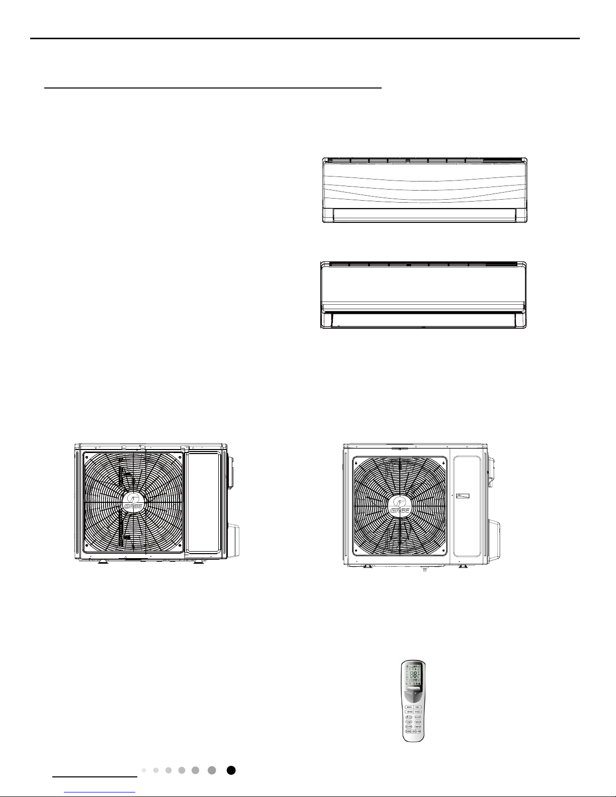
Indoor Unit
GWH18RC-K3DNA3G/I(Cold Plasma)(WIFI)
GWH24RD-K3DNA3G/I(Cold Plasma)(WIFI)
GWH18RC-K3DNA5G/I(Cold Plasma)(WIFI)
GWH24RD-K3DNA5G/I(Cold Plasma)(WIFI)
Outdoor Unit
GWH18MC-K3DNE3G/O GWH24MD-K3DNE3G/O
Remote Controller
YAA1FB

2
Technical Information
Service Manual
2. Specications
2.1 Specication Sheet
Model
GWH18RC-K3DNA3G(Cold Plasma)(WIFI)
GWH18RC-K3DNA5G(Cold Plasma)(WIFI)
Product Code
CB302002901
CB304002503
Power
Supply
Rated Voltage V~ 220-240
Rated Frequency Hz 50
Phases 1
Power Supply Mode outdoor
Cooling Capacity W 5275(1260~6600)
Heating Capacity W 5800(1120~6800)
Cooling Power Input W 1625(380~2650)
Heating Power Input W 1760(350~2650)
Cooling Power Current A 7.2
Heating Power Current A 7.8
Rated Input W 2650
Rated Current A 11.8
Air Flow Volume(SH/H/M/L/SL) m
3
/h 850/780/650/550/-
Dehumidifying Volume L/h 1.80
EER W/W 3.25
COP W/W 3.30
SEER W/W 6.1
HSPF W/W /
Application Area m
2
23-34
Indoor Unit
Model of indoor unit
GWH18RC-K3DNA3G/I(Cold Plasma)(WIFI)
GWH18RC-K3DNA5G/I(Cold Plasma)(WIFI)
Indoor Unit Product Code
CB302N02900
CB304N02503
Fan Type Cross-ow
Diameter Length(DXL) mm Φ98X710
Fan Motor Cooling Speed(SH/H/M/L/SL) r/min 1350/1200/1000/800/Fan Motor Heating Speed(SH/H/M/L/SL) r/min 1420/1250/1100/950/Output of Fan Motor W 20
Fan Motor RLA A 0.31
Fan Motor Capacitor μF 1.5
Evaporator Form Aluminum Fin-copper Tube
Pipe Diameter mm Φ7
Row-n Gap mm 2-1.4
Coil Length (LXDXW) mm 715X25.4X304.8
Swing Motor Model MP28VB
Output of Swing Motor W 2
Fuse A 3.15
Sound Pressure Level (SH/H/M/L/SL) dB (A) 45/43/37/33/-
Sound Power Level (SH/H/M/L/SL) dB (A) 58/53/50/45/-
Dimension (WXHXD) mm 945X298X211
Dimension of Carton Box (LXWXH) mm 1010X380X285
Dimension of Package (LXWXH) mm 1013X383X300
Net Weight kg 13
Gross Weight kg 16
3
Technical Information
Service Manual
Outdoor Unit
Model of Outdoor Unit GWH18MC-K3DNE3G/O
Outdoor Unit Product Code CB404W03401
Compressor Manufacturer/Trademark ZHUHAI LANDA COMPRESSOR CO.,LTD
Compressor Model QXA-B141zF030A
Compressor Oil 68EP
Compressor Type Rotary
L.R.A. A 25
Compressor RLA A 7.2
Compressor Power Input W 1440
Overload Protector 1NT11L-6233 or KSD115
o
C or HPC115/95U1
Throttling Method Capillary
Operation Temp
o
C 16~30
Ambient Temp (Cooling)
o
C -15~43
Ambient Temp (Heating)
o
C -20~24
Condenser Form Aluminum Fin-copper Tube
Pipe Diameter mm Φ7
Rows-n Gap mm 2-1.4
Coil Length (LXDXW) mm 851X38.1X660
Fan Motor Speed rpm 750
Output of Fan Motor W 60
Fan Motor RLA A /
Fan Motor Capacitor μF /
Air Flow Volume of Outdoor Unit m
3
/h 3200
Fan Type Axial-ow
Fan Diameter mm Φ520
Defrosting Method Automatic Defrosting
Climate Type T1
Isolation I
Moisture Protection IP24
Permissible Excessive Operating Pressure
for the Discharge Side
MPa 4.3
Permissible Excessive Operating Pressure
for the Suction Side
MPa 2.5
Sound Pressure Level (H/M/L) dB (A) 56/-/-
Sound Power Level (H/M/L) dB (A) 66/-/-
Dimension (WXHXD) mm 963X700X396
Dimension of Carton Box (LXWXH) mm 1026X455X735
Dimension of Package (LXWXH) mm 1029X458X750
Net Weight kg 45
Gross Weight kg 49.5
Refrigerant R410A
Refrigerant Charge kg 1.35
Connection
Pipe
Length m 5
Gas Additional Charge g/m 20
Outer Diameter Liquid Pipe mm Φ6
Outer Diameter Gas Pipe mm Φ12
Max Distance Height m 10
Max Distance Length m 25
Note: The connection pipe applies metric diameter.
The above data is subject to change without notice; please refer to the nameplate of the unit.
4
Technical Information
Service Manual
Model
GWH24RD-K3DNA3G(Cold Plasma)(WIFI)
GWH24RD-K3DNA5G(Cold Plasma)(WIFI)
Product Code
CB302003002
CB304002802
Power
Supply
Rated Voltage V~ 220-240
Rated Frequency Hz 50
Phases 1
Power Supply Mode outdoor
Cooling Capacity W 6450(2530~6800)
Heating Capacity W 7000(2530~7600)
Cooling Power Input W 2180(600~2650)
Heating Power Input W 2220(600~2800)
Cooling Power Current A 9.7
Heating Power Current A 9.8
Rated Input W 2800
Rated Current A 12.4
Air Flow Volume(SH/H/M/L/SL) m
3
/h 1000/800/700/550/-
Dehumidifying Volume L/h 2
EER W/W 2.96
COP W/W 3.15
SEER W/W 6.1
HSPF W/W /
Application Area m
2
27-42
Indoor Unit
Model of indoor unit
GWH24RD-K3DNA3G/I(Cold Plasma)(WIFI)
GWH24RD-K3DNA5G/I(Cold Plasma)(WIFI)
Indoor Unit Product Code
CB302N03002
CB304N02802
Fan Type Cross-ow
Diameter Length(DXL) mm Φ100X765
Fan Motor Cooling Speed(SH/H/M/L/SL) r/min 1350/1150/950/850/Fan Motor Heating Speed(SH/H/M/L/SL) r/min 1400/1200/1000/900/Output of Fan Motor W 35
Fan Motor RLA A 0.31
Fan Motor Capacitor μF 2.5
Evaporator Form Aluminum Fin-copper Tube
Pipe Diameter mm Φ7
Row-n Gap mm 2-1.5
Coil Length (LXDXW) mm 765X25.4X342.9
Swing Motor Model MP35XX
Output of Swing Motor W 2.5
Fuse A 3.15
Sound Pressure Level (SH/H/M/L/SL) dB (A) 51/47/42/39/-
Sound Power Level (SH/H/M/L/SL) dB (A) 61/57/52/49/-
Dimension (WXHXD) mm 1018X315X230
Dimension of Carton Box (LXWXH) mm 1083X395X313
Dimension of Package (LXWXH) mm 1086X398X328
Net Weight kg 15
Gross Weight kg 18.5
5
Technical Information
Service Manual
The above data is subject to change without notice; please refer to the nameplate of the unit.
Outdoor Unit
Model of Outdoor Unit GWH24MD-K3DNE3G/O
Outdoor Unit Product Code CB404W03801
Compressor Manufacturer/Trademark ZHUHAI LANDA COMPRESSOR CO.,LTD
Compressor Model QXA-B141zF030A
Compressor Oil 68EP
Compressor Type Rotary
L.R.A. A 25
Compressor RLA A 7.2
Compressor Power Input W 1440
Overload Protector 1NT11L-6233 or KSD115
o
C or HPC115/95U1
Throttling Method Capillary
Operation Temp
o
C 16~30
Ambient Temp (Cooling)
o
C -15~43
Ambient Temp (Heating)
o
C -20~24
Condenser Form Aluminum Fin-copper Tube
Pipe Diameter mm Φ7
Rows-n Gap mm 2-1.4
Coil Length (LXDXW) mm 984X38.1X748
Fan Motor Speed rpm 800
Output of Fan Motor W 90
Fan Motor RLA A /
Fan Motor Capacitor μF /
Air Flow Volume of Outdoor Unit m
3
/h 4000
Fan Type Axial-ow
Fan Diameter mm Φ552
Defrosting Method Automatic Defrosting
Climate Type T1
Isolation I
Moisture Protection IP24
Permissible Excessive Operating Pressure for
the Discharge Side
MPa 4.3
Permissible Excessive Operating Pressure for
the Suction Side
MPa 2.5
Sound Pressure Level (H/M/L) dB (A) 58/-/-
Sound Power Level (H/M/L) dB (A) 68/-/-
Dimension (WXHXD) mm 1000X790X427
Dimension of Carton Box (LXWXH) mm 1080X485X840
Dimension of Package (LXWXH) mm 1083X488X855
Net Weight kg 55
Gross Weight kg 60
Refrigerant R410A
Refrigerant Charge kg 1.80
Connection
Pipe
Length m 5
Gas Additional Charge g/m 50
Outer Diameter Liquid Pipe mm Φ6
Outer Diameter Gas Pipe mm Φ16
Max Distance Height m 10
Max Distance Length m 25
Note: The connection pipe applies metric diameter.
6
Technical Information
Service Manual
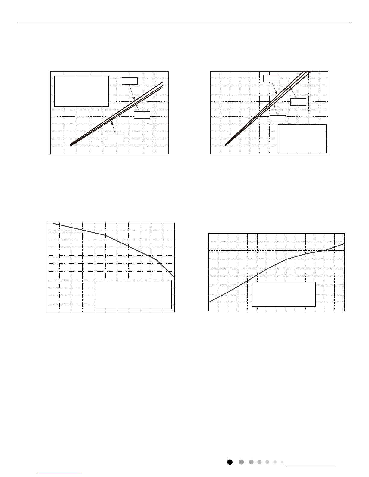
2.2 Operation Characteristic Curve
2.3 Capacity Variation Ratio According to Temperature
01020304050607090010 20 30 40 50 60 70 80 90 100 120 110
80
11
10
9
8
7
6
5
4
3
2
1
0
Compressor speed (rps)
) A ( t n e r r u C
11
10
9
8
7
6
5
4
3
2
1
0
Compressor speed (rps)
) A ( t n e r r u C
220V
230V
240V
220V
230V
240V
01020304050607090010 20 30 40 50 60 70 80 90 100 120110
80
11
10
9
8
7
6
5
4
3
2
1
0
Compressor speed (rps)
)A(tnerruC
11
10
9
8
7
6
5
4
3
2
1
0
Compressor speed (rps)
)A(tnerruC
220V
230V
240V
220V
230V
240V
Conditions
Indoor: DB27°C/WB19°C
Outdoor: DB35°C/WB24°C
Indoor air flow: High
Pipe length: 5m
Conditions
Indoor: DB27°C/WB19°C
Outdoor: DB35°C/WB24°C
Indoor air flow: High
Pipe length: 5m
Conditions
Indoor: DB20°C/WB15°C
Outdoor: DB7°C/WB6°C
Indoor air flow: High
Pipe length: 5m
Conditions
Indoor: DB20°C/WB15°C
Outdoor: DB7°C/WB6°C
Indoor air flow: High
Pipe length: 5m
Cooling Heating
Cooling Heating
32 33 34 35 36 37 38 39 43
–15 –10 –5
40 41 42
100
105
95
90
85
80
75
70
65
60
55
50
110
100
90
80
70
60
50
40
05710
Conditions
Indoor:DB27°C/WB19°C
Indoor air flow:Super High
Pipe length: 5m
Conditions
Indoor:DB20°C/WB15°C
Indoor air flow:Super High
Pipe length: 5m
Outdoor temp.(°C) Outdoor temp.(°C)
Capacity ratio (%)
Capacity ratio (%)
30
40
50
60
70
80
90
100
110
120
10
750-5-10-15-20
Outdoor temp.(oC)
Capacity ratio(%)
Conditions
Indoor:DB20°C/WB15°C
Indoor air flow:Super High
Pipe length: 5m
Cooling Heating
7
Technical Information
Service Manual
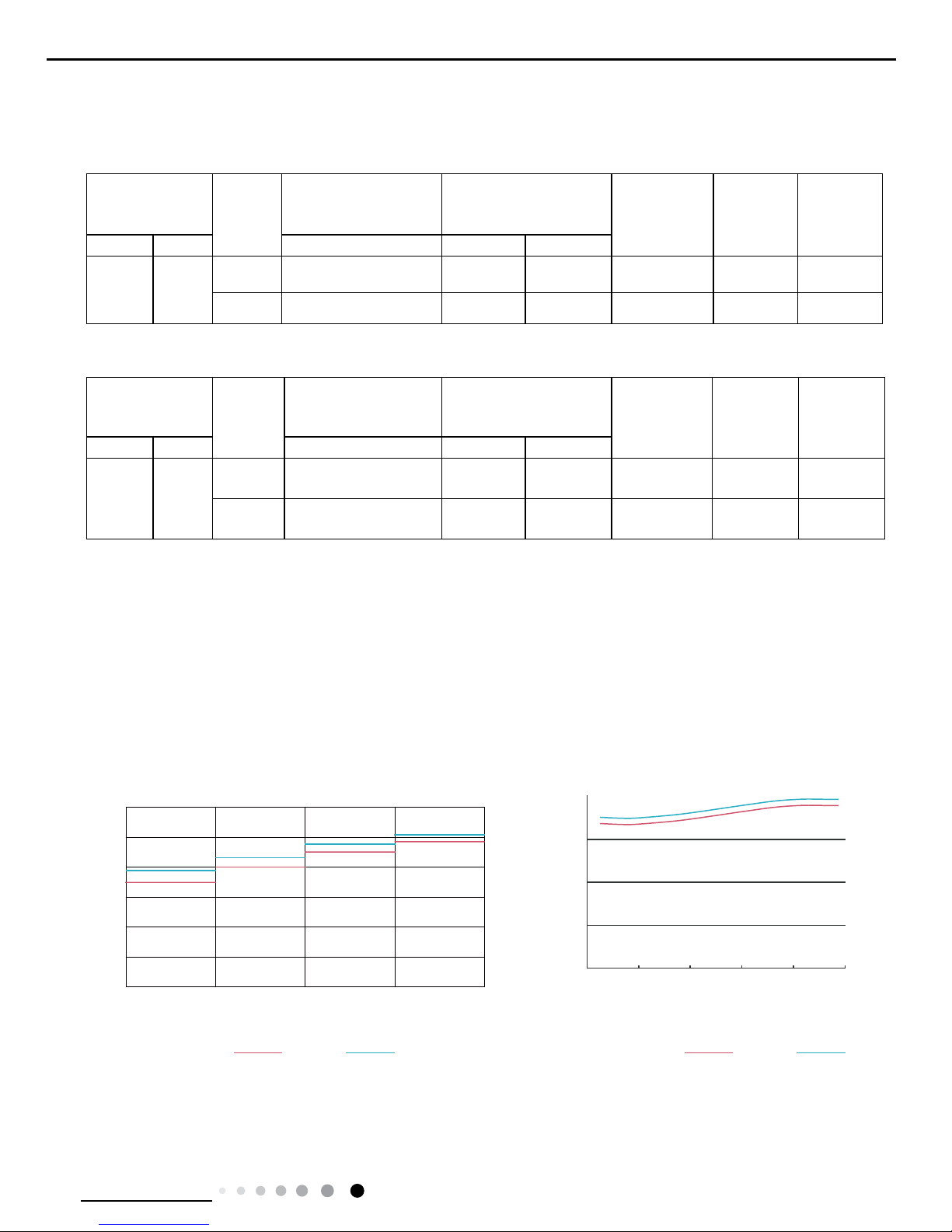
2.4 Cooling and Heating Data Sheet in Rated Frequency
Rated cooling
condition(
o
C)
(DB/WB)
Model
Pressure of gas pipe
connecting indoor and
outdoor unit
Inlet and outlet pipe
temperature of heat
exchanger
Fan speed of
indoor unit
Fan speed of
outdoor unit
Compressor
frequency
(Hz)
Indoor Outdoor P (MPa) T1 (
o
C) T2 (oC)
27/19 35/24
18K 0.8 to 1.0 12 to 14 80 to 40 Super High High 70
24K 0.9 to 1.1 10 to 12 80 to 40 Super High High 83
Rated heating
condition(
o
C)
(DB/WB)
Model
Pressure of gas pipe
connecting indoor and
outdoor unit
Inlet and outlet pipe
temperature of heat
exchanger
Fan speed of
indoor unit
Fan speed of
outdoor unit
Compressor
frequency
(Hz)
Indoor Outdoor P (MPa) T1 (
o
C) T2 (oC)
20/15 7/6
18K 2.2 to 2.4 70 to 40 1 to 5 Super High High 70
24K 2.5 to 2.7 70 to 40 1 to 5 Super High High 75
Instruction:
T1: Inlet and outlet pipe temperature of evaporator
T2: Inlet and outlet pipe temperature of condenser
P: Pressure at the side of big valve
Connection pipe length: 5 m.
Cooling:
Heating:
2.5 Noise Curve
20
30
40
50
60
20 0406080
100
Outdoor side noise
Indoor side noise
Compressor frequency/Hz
) A ( B d / e s i o N
18K
24K
18K
24K
60
50
40
30
20
10
0
Indoor Fan Motor Rotating Speed
Noice/dB(A)
low
Middle
High Super High
8
Technical Information
Service Manual
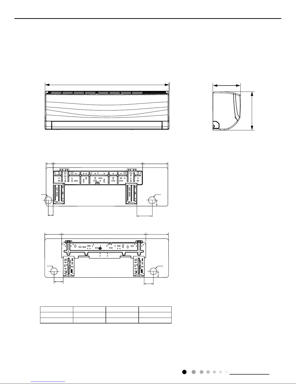
3. Outline Dimension Diagram
3.1 Indoor Unit
Unit:mm
Models W H D
18K 945 298 211
24K 1018 315 230
18K
24K
W
694
685 189
144
57
38
116
45
45
60
95
Φ55Φ55
Φ70 Φ70
194
D
H
NOTE:Take A3 panel for example
9
Technical Information
Service Manual
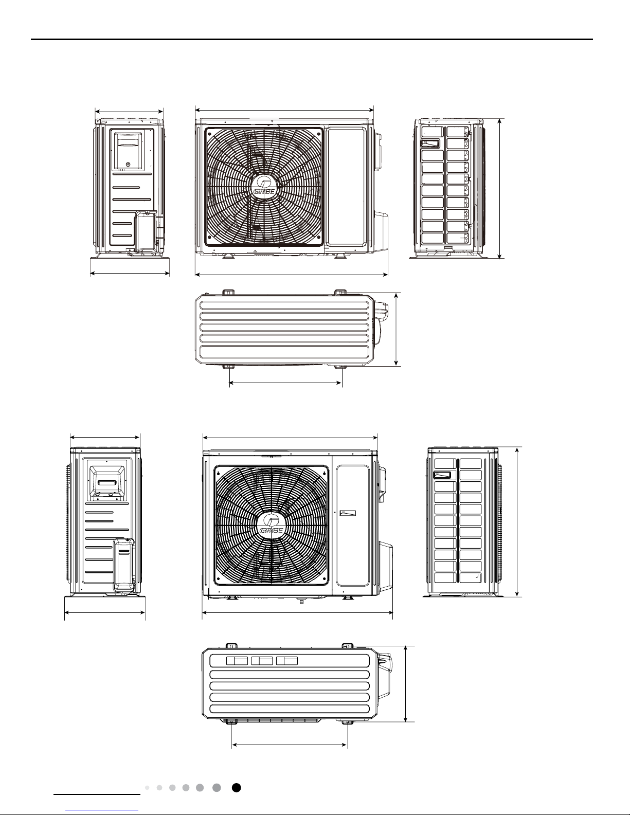
3.2 Outdoor Unit
Unit:mm
24K
18K
963
892
700
396
341
368
560
427
1000
920
610
370
790
395
10
Technical Information
Service Manual
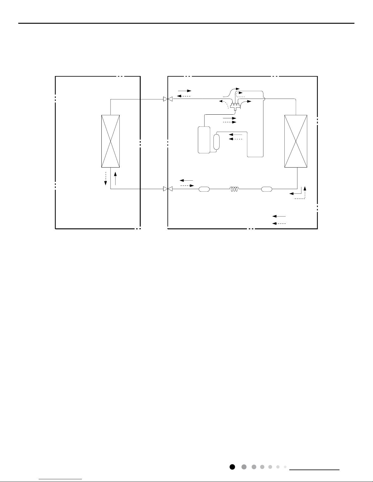
Indoor unit
Outdoor unit
COOLING
HEATING
4-Way valve
Discharge
Suction
Heat
exchanger
(evaporator)
Heat
exchanger
(condenser)
Valve
Valve
Liquid pipe
side
Gas pipe
side
Strainer CapillaryStrainer
Accumlator
Compressor
4. Refrigerant System Diagram
Connection pipe specication:
Liquid pipe:1/4" (6mm)
Gas pipe:1/2" (12mm)(18K)
Gas pipe:5/8" (16mm)(24K)
11
Technical Information
Service Manual
5. Electrical Part
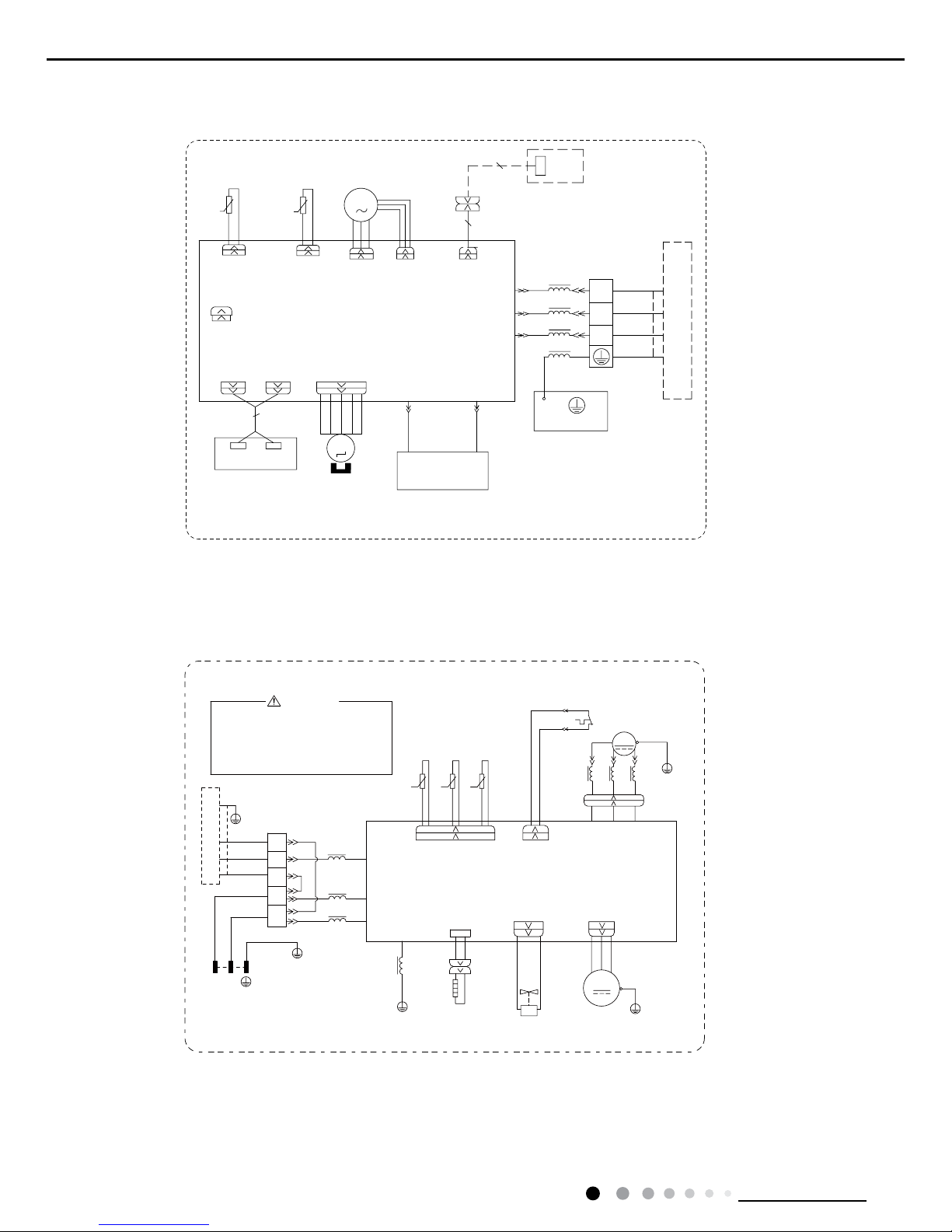
5.1 Wiring Diagram
● Indoor Unit
●Instruction
Symbol Symbol Color Symbol Symbol Color Symbol Name
WH White GN Green CAP Jumper cap
YE Yellow BN Brown COMP Compressor
RD Red BU Blue Grounding wire
YEGN Yellow/Green BK Black / /
VT Violet OG Orange / /
Note: Jumper cap is used to determine fan speed and the swing angle of horizontal lover for this model.
Model:GWH18RC-K3DNA3G/I(Cold Plasma)(WIFI) GWH18RC-K3DNA5G/I(Cold Plasma)(WIFI)
5'
*(1(5$725
&2/'3/$60$
%8
+($/7+1+($/7+/
$3
&$3
-803
35,17('&,5&8,7%2$5'
$3
',63',63
57
57
',63/$<%2$5'
5(&(,9(5$1'
78%(7(03
6(1625
52207(03
0
6:,1*8'
6(1625
:,),02'8/(
1
287'22581,7
<(*1
;7
%8
%.
%/2&.
7(50,1$/
1
3(
(9$325$725
<(*1
&20287
/$&/
%1
/
/
78%( 5220
02725
6:,1*
%8
%.
%1
)$1
3*3*)
0
02725
$3
&200$18$/
/WIFI
6:,1*8'
63610000385
12
Technical Information
Service Manual
Model:GWH24RD-K3DNA3G/I(Cold Plasma)(WIFI) GWH24RD-K3DNA5G/I(Cold Plasma)(WIFI)
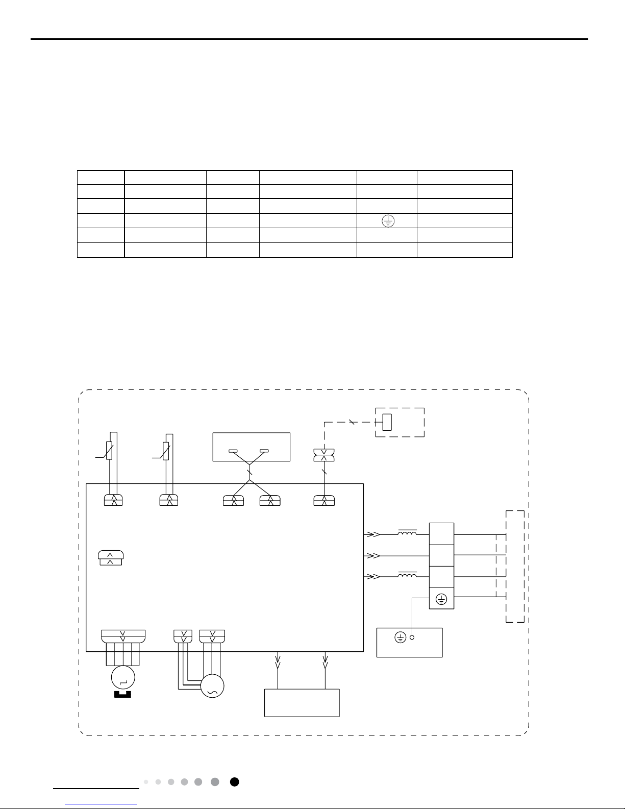
● Outdoor Unit
L2
50K15K20K
BN
WARNING
Please don't touch any terminal
when the voltage of terminal
P(DC+) and N(DC-) at AP1 is
higher than 30V to prevent the
risk of electric shock !
POWER
θ
θ
θ
COMP.
L1
WVU
PRINTED CIRCUIT BOARD
L1
PE
YEGN
FAN MOTOR
4WAY OFAN
VTVT
VALVE
4YV
4-WAY
M1
PE
MAGNETIC
PE
TERMINAL
BLOCK
YEGN
BU
BN
BU
BN
BK
RING
L1
INDOOR UNIT
XT1
BU
BK
BN
3
2
N(1)
L
N
PE
BU
YEGN
L
N
PE
YEGN
PE
COM_INNER
N1
AC_L
L3
L3
RING
MAGNETIC
L3
OVERLOAD PROTECTOR
T_SENSOR
YEGN
W(RD)V(YE)U(BU)
YEBU
RD
PE
PE
RT1 RT2 RT3
RD
OVC_COMP
WHWH
SAT
COMP
X1
YE
BU
WH
BK
TEMP.SENSOR
OUTTUBE
OUTROOM
TEMP.SENSOR
EXHAUST
TEMP.SENSOR
AP1
HEAT_B
EH
RD
BOTTOM
HEATER
BAND
RD
These circuit diagrams are subject to change without notice, please refer to the one supplied with the unit.
6(16256(1625
/$&/
%.
3(
522078%(
0
6:,1*8'
52207(03
57
$3
%1
3*
<(*1
0
%8
)$102725
287'22581,7
;7
1
78%(7(03
57
6:,1*
02725
&20287
1
3*)
&$3
-803
',63',63
$3
5(&(,9(5$1'
',63/$<%2$5'
(9$325$725
7(50,1$/
%/2&.
/
/
6:,1*8'
%8
%.
%1
<(*1
35,17('&,5&8,7%2$5'
+($/7+/
%8 5'
+($/7+1
*(1(5$725
&2/'3/$60$
/
/
:,),02'8/(
$3
&200$18$/
/WIFI
6361000034202
13
Technical Information
Service Manual
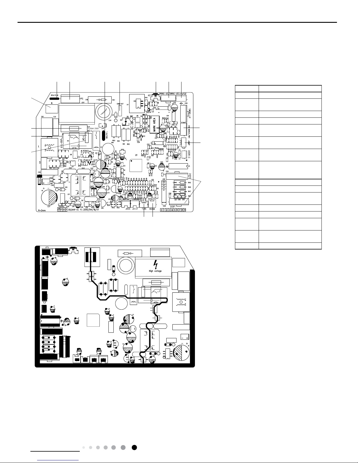
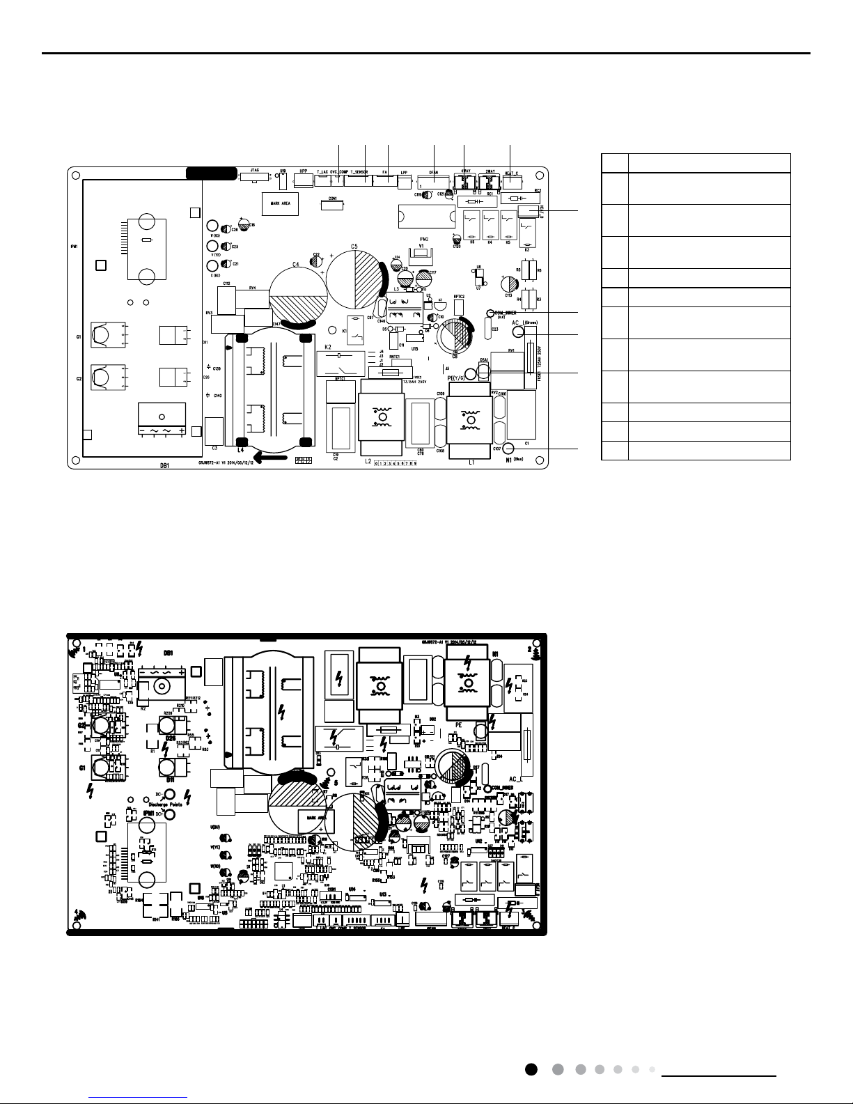
5.2 PCB Printed Diagram
● Top view
Indoor Unit
● Bottom view
No. Name
1 Interface of live wire
2
Interface of live wire for
outdoor control
3 Fuse
4 Interface of neutral wire
5
Interface of neutral wire for
health function
6
Control interface of PG
motor
7
Interface of live wire for
health function
8
Interface of indoor
unit and outdoor unit
communication
9 Auto button
10 Up & down swing
11
Feedback interface of
indoor fan
12 Jump
13 Interface of display
14
Ambient temperature
sensor interface
15
Indoor tube temperature
sensor interface
16 Detecting plate(WIFI )
1
2
3
4
5 6 7 8 9 10 11
12
16
13
1415
14
Technical Information
Service Manual
● Top view
Outdoor Unit
● Bottom view
No. Name
1
Terminal of compressor
overload protection
2
Terminal of temperature
sensor
3
Terminal of electronic
expansion valve
4
Terminal of outdoor fan
5
Terminal of 4-way valve
6
Terminal of compressor
electric heating
7
Terminal of chassis electric
heating
8
Terminal of indoor unit and
outdoor unit communication
9
Power supply live wire
10
Earthing wire
11
Power supply neutral wire
1 2 3 4 5 6
7
8
9
10
11
15
Technical Information
Service Manual
6. Function and Control
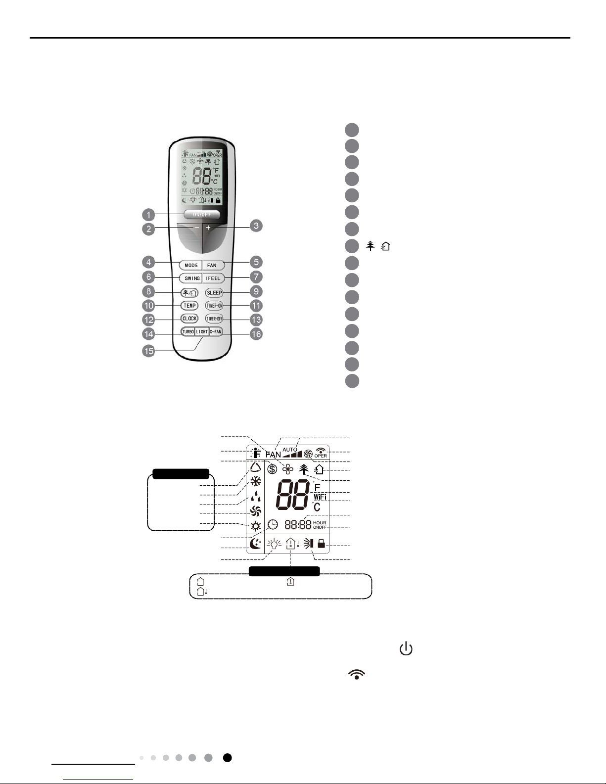
6.1 Remote Controller Introduction
Buttons on Remote Controller
Introduction
for Icons on Display Screen
Introduction for Buttons on Remote Controller
Note:
● After putting through the power, the air conditioner will give out a sound. Operation indictor "
" is ON (red indicator). After that, you
can operate the air conditioner by using remote controller.
● Under on status, pressing the button on the remote controller, the signal icon "
"on the display of remote controller will blink once
and the air conditioner will give out a “de” sound, which means the signal has been sent to the air conditioner.
● Under off status, set temperature and clock icon will be displayed on the display of remote controller (If timer on, timer off and light
functions are set, the corresponding icons will be displayed on the display of remote controller at the same time); Under on status, the
display will show the corresponding set function icons.
1. ON/OFF Button
1
2
5
4
6
7
8
11
12
13
9
14
15
ON/OFF button
- button
3
SWING button
FAN button
MODE button
I FEEL button
CLOCK button
10
TIMER-ON button
TIMER-OFF button
TURBO button
LIGHT button
16
X-FAN button
SLEEP button
TEMP button
button
/
+ button
Up & down swing
Child lock
set time
TIMER ON/TIMER OFF
turbo mode
X-fan
health mode
ventilation operation
send signal
set fan speed
light
Temp. display type
:Set temp.
:Outdoor ambient temp.
:Indoor ambient temp.
Sleep mode
Clock
Heat mode
Fan mode
Dry mode
Cool mode
Auto mode
I feel
Operation mode
8ć heating function
set temperature
wifi
16
Technical Information
Service Manual
Press this button to turn on the unit. Press this button again to turn off the unit.
2. - Button
Press this button to decrease set temperature. Holding it down above 2 seconds rapidly decreases set temperature. In AUTO mode, set
temperature is not adjustable.
3. + Button
Press this button to increase set temperature. Holding it down above 2 seconds rapidly increases set temperature. In AUTO mode, set
temperature is not adjustable.
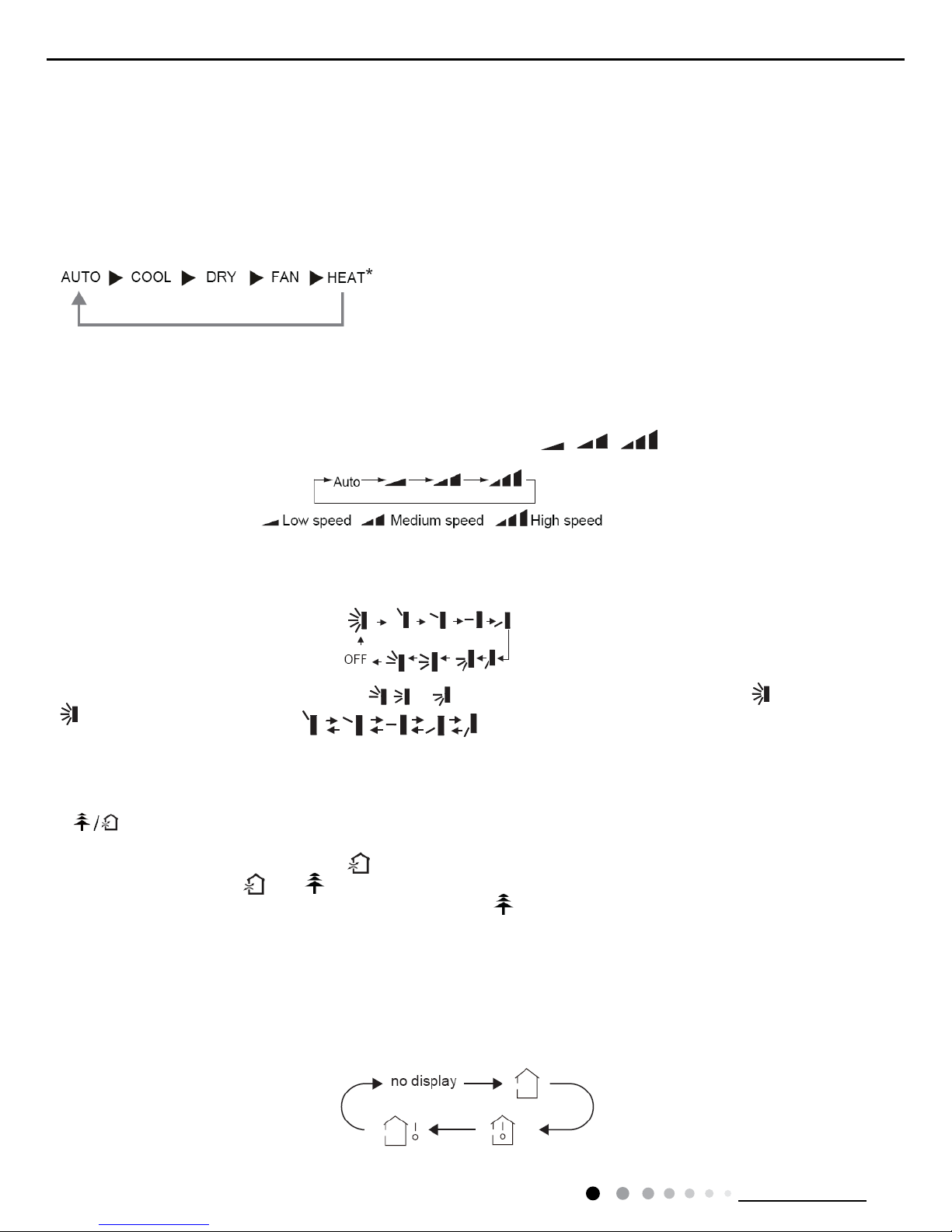
4. MODE Button
Each time you press this button, a mode is selected in a sequence that goes from AUTO, COOL, DRY, FAN, and HEAT*, as the following:
*Note:Only for models with heating function.
After energization, AUTO mode is defaulted. In AUTO mode, the set temperature will not be displayed on the LCD, and the unit will
automatically select the suitable operation mode in accordance with the room temperature to make indoor room comfortable.
(As for cooling only unit, it won’t have any action when it receives the signal of heating operation.)
5. FAN Button
This button is used for setting Fan Speed in the sequence that goes from AUTO,
, to , then back to Auto.
6. SWING Button
Press this button to set up &down swing angle, which circularly changes as below:
This remote controller is universal. If any command , or is sent out, the unit will carry out the command as
indicates the guide louver swings as:
7. I FEEL Button
Press this button to turn on I FEEL function. The unit automatically adjust temperature according to the sensed temperature. Press this
button again to cancel I FEEL function.
8.
Button
Press this button to achieve the on and off of healthy and scavenging functions in operation status. Press this button for the rst
time to start scavenging function; LCD displays "
". Press the button for the second time to start healthy and scavenging functions
simultaneously; LCD displays "
" and " ". Press this button for the third time to quit healthy and scavenging functions simultaneously.
Press the button for the fourth time to start healthy function; LCD display "
". Press this button again to repeat the operation above. (This
function is applicable to partial of models)
9. SLEEP Button
Press this button to go into the SLEEP operation mode. Press it again to cancel this function. This function is available in COOL, HEAT
(Only for models with heating function) or DRY mode to maintain the most comfortable temperature for you.
10. TEMP Button
Press this button can see indoor set temperature, indoor ambient temperature or outdoor ambient temperature on indoor unit’s display.
Temperature is set circularly by remote controller as below:
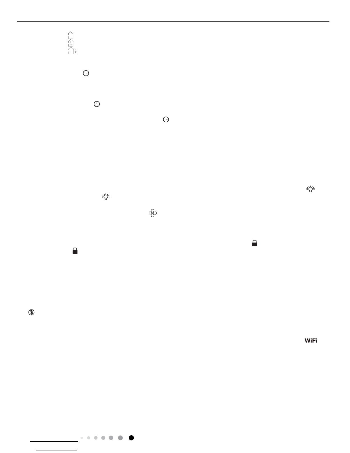
17
Technical Information
Service Manual
● When selecting " " by remote controller or no display, temperature indicator on indoor unit displays set temperature.
● When selecting "
" by remote controller, temperature indicator on indoor unit displays indoor ambient temperature.
● When selecting "
" by remote controller, temperature indicator on indoor unit displays outdoor ambient temperature.
11. TIMER-ON Button
Press this button to initiate the auto-ON timer. To cancel the auto-timer program, simply press this button again.
After press of this button,
disappears and "ON" blinks. 00:00 is displayed for ON time setting. Within 5 seconds, press + or - button to
adjust the time value. Every press of either button changes the time setting by 1 minute. Holding down either button rapidly changes the
time setting by 1 minute and then 10 minutes. Within 5 Seconds after setting,press TIMER ON button to conrm.
12. CLOCK Button
Press CLOCK button,blinking.
Within 5 seconds, pressing + or - button adjusts the present time. Holding down either button above 2
seconds increases or decreases the time by 1 minute every 0.5 second and then by 10 minutes every 0.5 second. During blinking after
setting, press CLOCK button again to conrm the setting, and
then will be constantly displayed.
13. TIMER-OFF Button
Press this button to initiate the auto-off timer. To cancel the auto-timer program, simply press the button again. TIMER OFF setting is the
same as TIMER ON.
14. TURBO Button
Press this button to activate / deactivate the Turbo function which enables the unit to reach the preset temperature in the shortest time.
In COOL mode, the unit will blow strong cooling air at super high fan speed. In HEAT mode, the unit will blow strong heating air at super
high fan speed.
15. LIGHT Button
Press LIGHT button to turn on the display's light and press this button again to turn off the display's light. If the light is turned on,
is
displayed. If the light is turned off,
disappears.
16. X-FAN Button
Pressing X-FAN button in COOL or DRY mode, the icon
is displayed and the indoor fan will continue operation for 10 minutes in order
to dry the indoor unit even though you have turned off the unit.
After energization, X-FAN OFF is defaulted. X-FAN is not available in AUTO, FAN or HEAT mode.
17. Combination of "+" and "-" buttons: About lock
Press "+" and "-" buttons simultaneously to lock or unlock the keypad. If the remote controller is locked,
is displayed. In this case,
pressing any button,
blinks three times.
18. Combination of "MODE" and "-" buttons:About switch between Fahrenheit and centigrade
At unit OFF, press "MODE" and "-" buttons simultaneously to switch between °C and °F.
19. Combination of "TEMP" and "CLOCK" buttons:About Energy-saving Function
Press "TEMP" and "CLOCK" simultaneously in COOL mode to start energy-saving function.Nixie tube on the remote controller displays
"SE". Repeat the operation to quit the function.
20. Combination of "TEMP" and "CLOCK" buttons:About 8°C Heating Function
Press "TEMP" and "CLOCK" simultaneously in HEAT mode to start 8°C Heating Function Nixie tube on the remote controller displays
"
" and a selected temperature of "8°C".(46°F if Fahrenheit is adopted). Repeat the operation to quit the function.
21. About Back-lighting Function
The unit lights for 4s when energizing for the rst time, and 3s for later press.
22. Combination of "MODE" and "TURBO" buttons:About WIFI Function
Press "MODE" and "TURBO" button simultaneously to turn on or turn off WIFI function. When WIFI function is turned on, the " "
icon will be displayed on remote controller; Long press "MODE" and "TURBO" buttons simultaneously for 10s, remote controller will send
WIFI reset code and then the WIFI function will be turned on. WIFI function is defaulted ON after energization of the remote controller.
23. About HEALTH function (COLD PLASMA)
Turn on the unit, start up the fan (Breezing and X-FAN are excluded) and press HEATLTH button on remote controller to start health
function (If there is not HEALTH button on remote controller, the unit defaults health function ON.)
24. Operation guide
1. After putting through the power, press "ON/OFF" button on remote controller to turn on the air conditioner.
2. Press "MODE" button to select your required mode: AUTO, COOL, DRY, FAN,HEAT.
3. Press "+" or "-" button to set your required temperature. (Temperature can’t be adjusted under auto mode).
4. Press "FAN" button to set your required fan speed: auto, low, medium and high speed.
5. Press "SWING" button to select fan blowing angle.
18
Technical Information
Service Manual
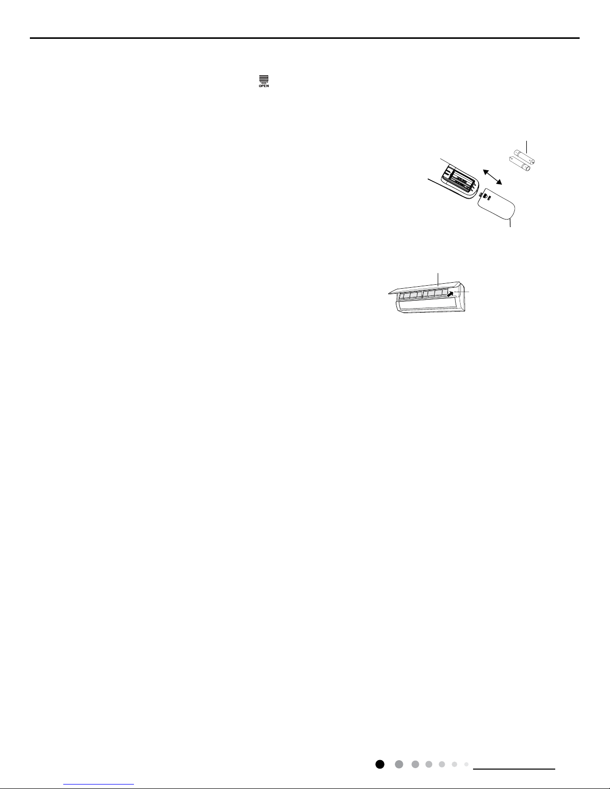
If remote controller is lost or damaged, please use auxiliary button to turn on or turn
off the air conditioner. The operation in details are as below: As shown in the g.
Open panel, press aux. button to turn on or turn off the air conditioner. When the air
conditioner is turned on, it will operate under auto mode.
Emergency Operation
Emergency operation
switch
Panel
Note:
● During operation, point the remote control signal sender at the receiving window
on indoor unit.
● The distance between signal sender and receiving window should be no more than
8m, and there should be no obstacles between them.
● Signal may be interfered easily in the room where there is fluorescent lamp or
wireless telephone; remote controller should be close to indoor unit during operation.
● Replace new batteries of the same model when replacement is required.
● When you don’t use remote controller for a long time, please take out the batteries.
● If the display on remote controller is fuzzy or there’s no display, please replace
batteries.
1.Press the back side of remote controller marked with“
”as shown in the g, and then push out the cover
of battery box along the arrow direction.
2. Replace two 7# (AAA 1.5V) dry batteries, and make sure the position of “+” polar and “-“ polar are correct.
3. Reinstall the cover of battery box.
Replacement of Batteries in Remote Controller
battery
Cover of battery box
remove
reinstall

19
Technical Information
Service Manual
6.2 Operation of Smart Control (Smart Phone, Tablet PC)
Operation Instructions
Download and install APP
Scan the following QR code (also indicated on the package) with your smart phone and download Wi Smart
.
Conguration
Before operation, please nish the following conguration in order to realize Wi control and the connection between air conditioner
and mobile phone.
1.Short-distance control setting for air conditioner using wi hotspot
Step 1: Air conditioner wi is set to AP mode in factory. You can search the air conditioner wi hotspot through your smart phone. The
name of wi hotspot is the last 8 numbers of the air condtioner mac address. Password is 12345678.
Step 2: Open Gree APP and the screen will show the air conditioner that you just connected. Click this air conditioner to enter and
realize short-distance control, as shown below. Please refer to "Functions introduction" for specic control methods.
Install the APP according to its guidance. When successfully installed, your smart phone homepage will show this icon
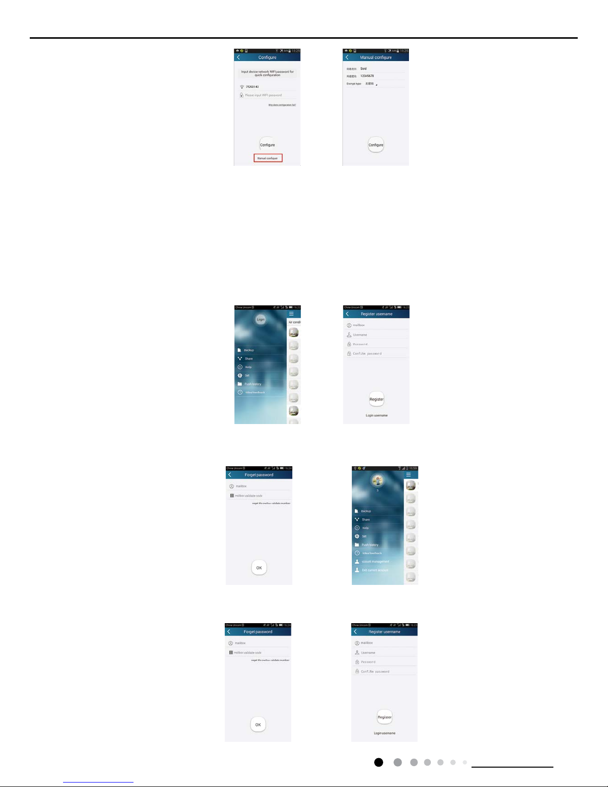
2.Short-distance and long-distance control setting for air conditioner connecting router
Step 1: Under short-distance control, return to the homepage "Home Control". Click at the top right corner and select "Add
device" to enter the page "Congure".
Step 2: Click "Manual conguration". Input router’s name, password and encryption type.
20
Technical Information
Service Manual
Functions introduction
1.User registration
Purpose: To realize long-distance control
Operation instruction: For the rst time login, you have to register a new username. If you already have a username, skip the registration
step and input email address and password on the "Login Page" to log in. If password is forgotton, you can reset the password.
Operation steps:
(1) Login with username: Slide the "Home control" page and enter the "Menu" page on the left. Click "Login" to enter the page "Login
username". New user must rst register a username. Click "Register username".
(2) Input email address and click "Get the verication code". Wait until you receive the verication code. Input the code and click "OK" to
log in. Username will appear,as 3 in the picture.
(3) If password is forgotten, you can reset the password with your phone number.Click "Forget password" and enter the page "Forget
password". Click "Verication code" to get the email vercation code. Input a new password and click "OK" to login.
If conguration succeeds, APP will notify user that conguration is successful and displays its homepage. If conguration failes, APP will
notify user that conguation failes. In this case, please repeat the above steps until the APP shows that conguration is successful.
21
Technical Information
Service Manual
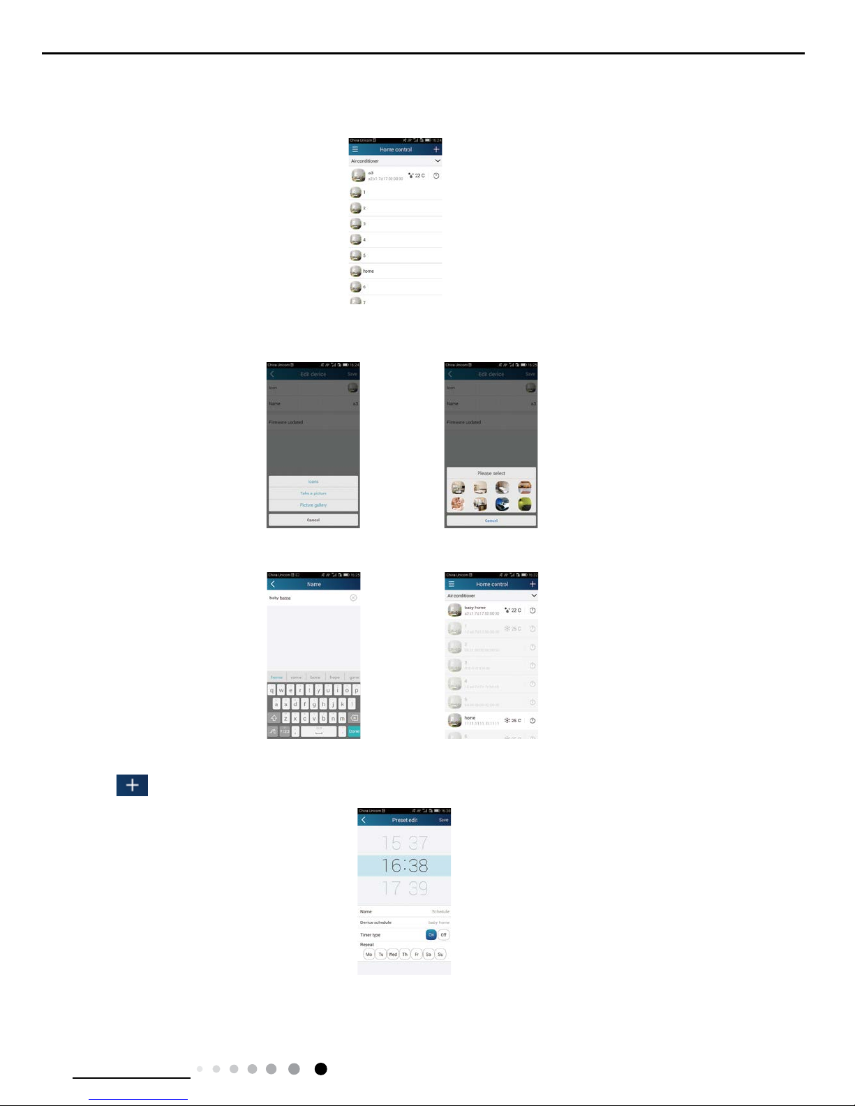
2.Personal setting
Purpose: Set name (device name, preset name, etc.) and image (device image) for the convenience of user identication.
(1) Set device name
After quick conguration, a list of controllable smart devices will be generated.
Step 1: Click and hold "a3" to enter the page "Edit device". Click "Image" to select the source of image. Select from "Default images" or
"Take a picture" or "Picture gallery" and save an image.
Step 2: Click "Name" to change device name. As shown in the picture, device name is changed to "baby home". Save it and the new
device name will be shown.
(2) Set preset name
Step 1: Click at the top right corner of the homepage "Home control". Select "Add preset" and enter the page "Preset edit".
Step 2: Choose the time. Click "Name" to edit it. As shown in the picture, it is edited to "baby room". For timer type, select On. Then select
the repeat days. Save the
setting of preset name.
22
Technical Information
Service Manual
(3) Set device image
Please refer to the steps as instructed in 2(1)
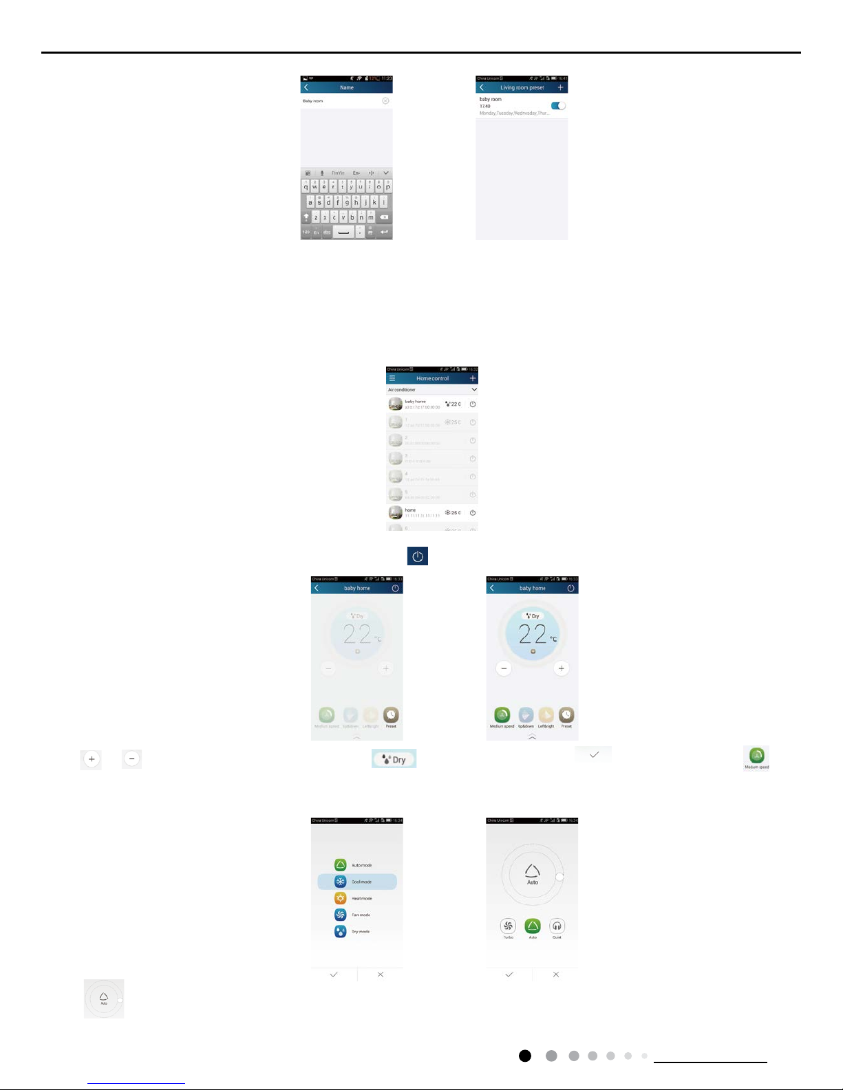
3.Control functions
(1) Common control functions: General control on the operation of smart devices(On/Off, temperature, fan speed, mode, etc.) and the
setting of advanced functions(Air exchange, dry, heath, light, sleep, energy saving lower limit).
Step 1: General control Enter the homepage "Home control" rst. Take "baby home"as an example.
Click "Baby home" and enter the air conditioner control page. Click to turn on the control switch.
Click or to increase or decrease temperature. Click to adjust working mode. Click to save the mode. Click
to enter the page of fan speed adjustment.
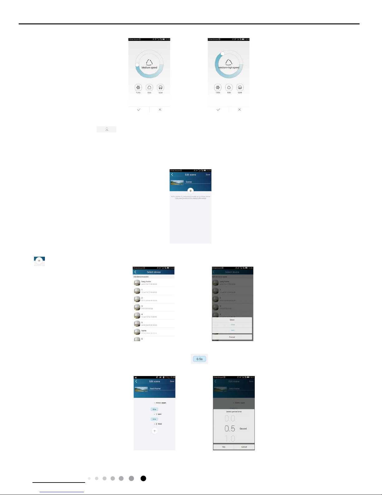
Click and go around the circle to select fan speed. Then click √ to save the selection.
23
Technical Information
Service Manual
Step 2: Advanced settings Click to enter advanced settings. You may select "Air", "Dry", "Health", "Light", "Sleep" or "Energy saving/
upper limit".
(2) Advanced control functions: Set scene; Preset; Link; Infrared control (limited to the smart phone with infrared emitter)
Set scene: Preset the operation of several devices by one click On the page "Home control", click the image of "Home control" to enter the
page "Edit scene".
Click "Add scene" and edit the scene name, for example, "back home". Add execution devices.
Click to add commands. On the page "Select device", select the air conditioner "home". Then select "ON" or "OFF".
Continue to select the next execution device as instructed above. Click to set the interval.
24
Technical Information
Service Manual
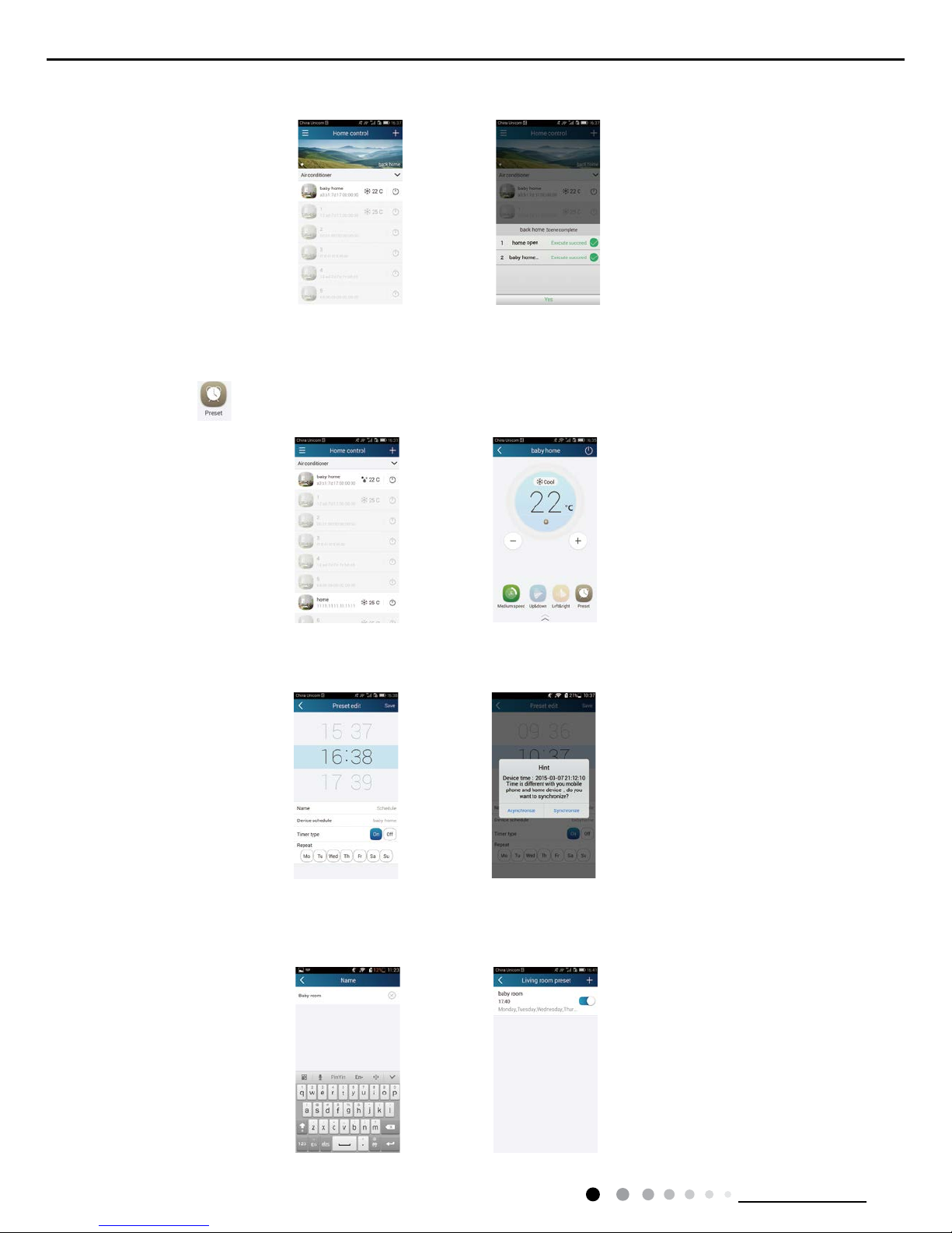
Save it and the scene "back home" will be executed. You may also view the execution condition of the scene.
(3) Preset includes single-device preset and multi-device preset Single-device preset: This can preset a certain device to execute On/Off at
a specic time.
On the homepage "Home control", take air conditioner "baby home" as an example.
Click the bottom icon on the page "baby room" to enter the page "Preset edit".
Slide up and down to set the time. If you want to synchronize the time, choose "Synchronize".
Click "Name" to dene the preset name.
Preset device defaults to "baby home". Select "On" as the timer type. Select "Repeat" days to complete the preset.
25
Technical Information
Service Manual
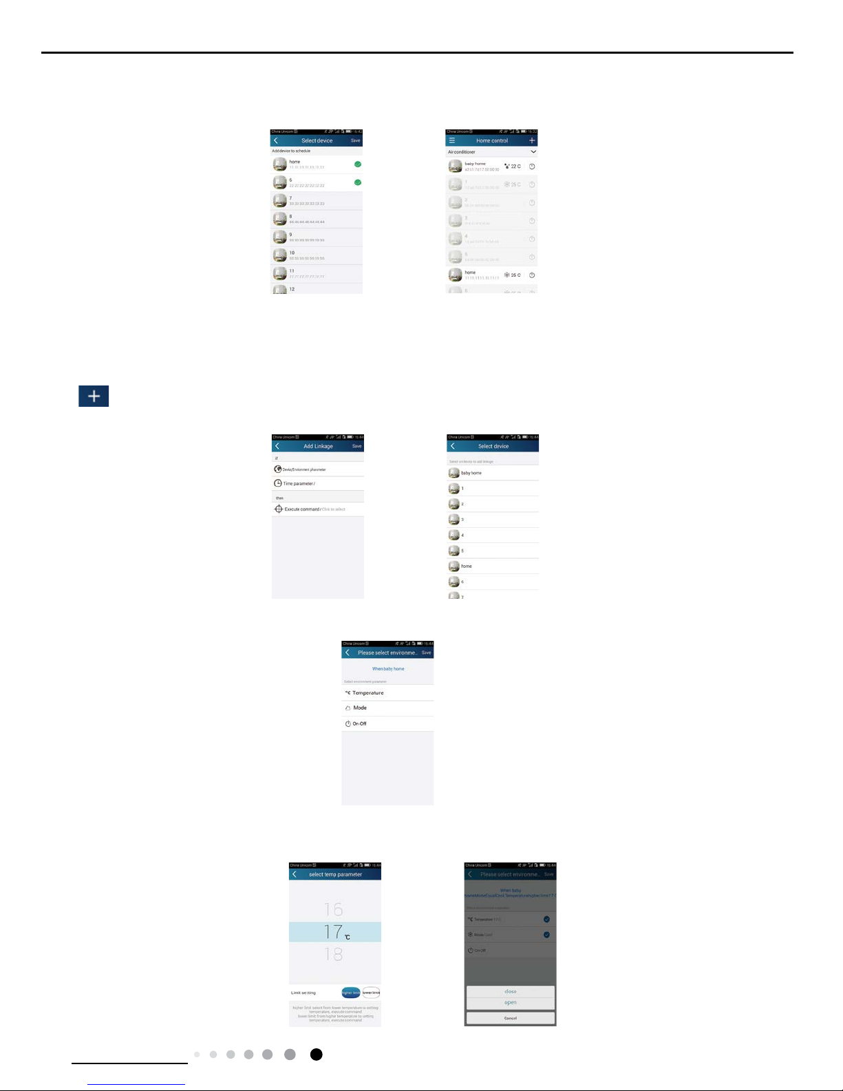
Multi-device preset: This can preset multiple devices to execute at a specied time Please refer to the instructions as how to set preset
time, name, timer type and repeat days of a single device.
On the page "Select device", select one or more devices to preset multiple devices.Then return to the page "Home control".
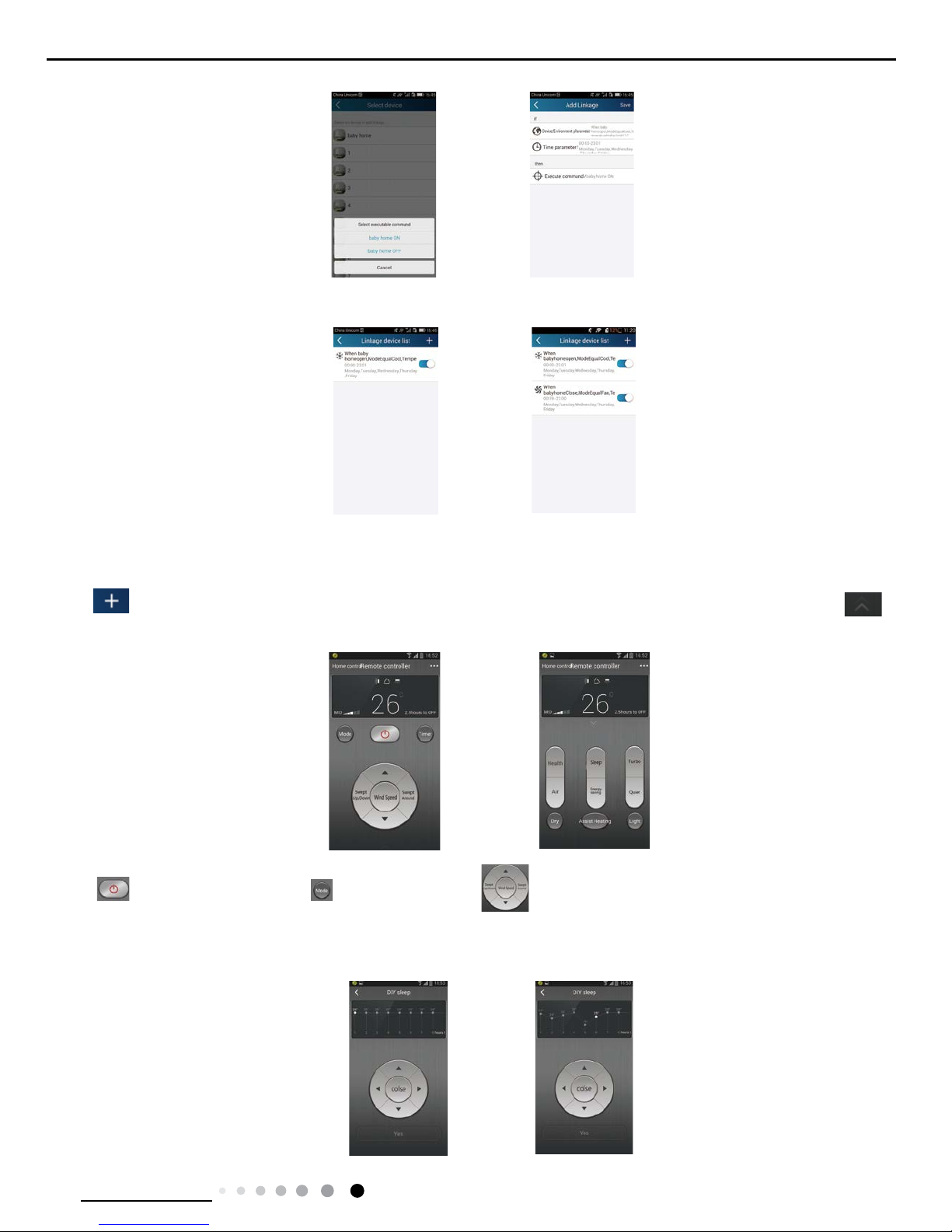
(4) Link(This function is applicable to partial of models)
set in the master device, slave devices will execute commands to realize devices Select a master device. When the environment has
satised the parameters as linkage.
Step 1: Set the parameters of master device (Select master device, select environment parameters, select master device status).
Click at the top right corner of the homepage "Home control". Select "Link" and enter the page "Add linkage". Select "Device
parameter" to enter the page "Select device". Take "baby home" as an example. Select "baby home".
Enter the page "Select environment parameter".
Select "Temperature" to enter the page "Select temp parameter". Slide up and down to adjust temperature. Then select "upper limit" or
"lower limit".Click "Mode" and "On-Off" to select the status of master device. Then save the data.
26
Technical Information
Service Manual
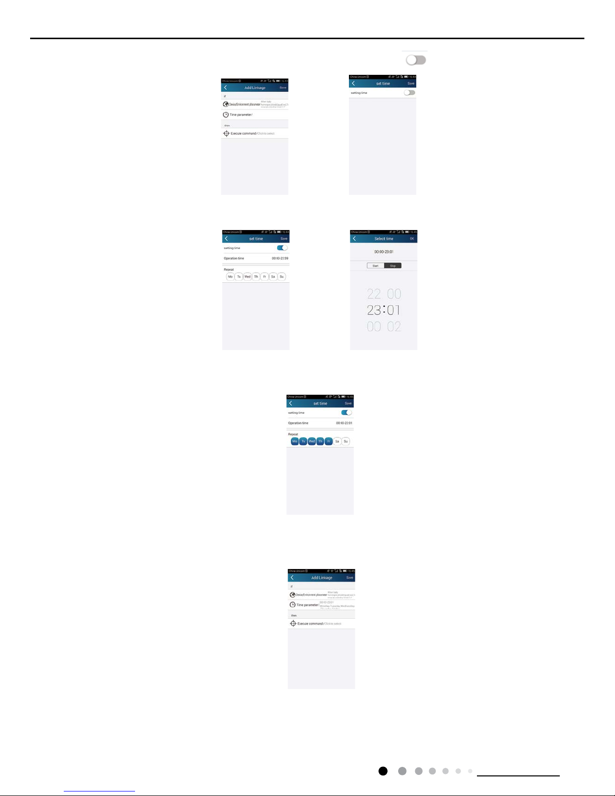
Step 2: Set linkage time parameter. Click "Time parameter" to enter the page "Set time". Slide right to turn on the setting time.
Click "Execution time" to select the start time and stop time. Then click "OK" to save the data.
Click the days below "Repeat". Select repeat days and save the data.
Step 3: Select "Execute command"
Select "Execute command" and enter the page "Select device".
Click the name of device that needs to be controlled. Select "ON" or "OFF" and then save the data to complete the linakge.
27
Technical Information
Service Manual
Click "Save". Repeat the above steps to set linkage for several scenes.
(5) Infrared control (limited to the smart phone with infrared emitter)
Function: Smart phone can be used like a remote controller.
Click at the top right corner of the homepage "Home control". Select "Infrared" and enter the page "Remote controller". Click
and slide up to enter the page of advanced functions.
Click to turn on the device. Click to select mode. Click to adjust fan speed, etc. Click "Health", "Energy saving",
"Sleep", etc. to set advanced functions.
Click "Sleep" to enter the page "Sleep", on which "Traditional sleep", "Expert sleep","DIY sleep" can be selected. For example, click "DIY
sleep". Then click the left and right arrows to select sleep time and up and down arrows to adjust temperature at a specied sleep time.
 Loading...