

Page 1

Thank you for choosing Air Conditioners, please read this owner’s manual carefully before operation
and retain it for future reference.If you have lost the Owner’s Manual, please contact the local agent
or visit www.gree.com or send email to global@gree.com.cn for electronic version.
GREE reserves the right to interpret this manual which will be subject to any change due to product
improvement without further notice.
GREE Electric Appliances, Inc. of Zhuhai reserves the final right to interpret this manual.
User's Manual for Wired
Controller XK55
Page 2

User’s Notice
The power supply method for all indoor units must be unified.
Prohibit installing the wired controller at wet or sunshine places.
Do not knock, throw or frequently disassemble the wired controller.
Dot not operate the wired controller with wet hands.
The photos in this instruction manual is only for reference, Please refer to the
actual products for the final effect.
In one system network, you must set one indoor unit as the master indoor unit.
Others are slave indoor unit.
The operation mode for the system is basing on that of master indoor unit.
Master indoor unit can switch the mode freely, while slave indoor unit can’t
switch to the mode which will conflict with the master indoor unit.
When the operation mode of indoor unit is conflicting with that of system
because the master indoor unit is changing mode, the operation mode of
slave indoor unit will switch to the operation mode of system automatically.
When two wired controllers control one (or more) indoor unit(s), the address
of wired controller should be different.
Functions with “*” are optional for indoor units. If a function is not included in
an indoor unit, wired controller can’t set the function, or setting of this function
is invalid to the indoor unit
Page 3

CONTENTS
1 Installation Instruction ............................................................ 1
1.1 Selection requirement for communication wire ......................... 2
1.2 Installation requirement ............................................................. 3
1.3 Wiring requirement .................................................................... 4
1.4 Installation ................................................................................. 7
1.5 Disassembly .............................................................................. 8
2 Display Instruction ................................................................. 9
2.1 Outside view.............................................................................. 9
2.2 Buttons instruction .................................................................. 10
2.3 Icon instruction ........................................................................ 12
3 Operation Instruction ........................................................... 13
3.1 Summary ................................................................................. 13
3.2 Page instruction ...................................................................... 14
4 Special function explanation ................................................ 33
4.1 Remote shield function ........................................................... 33
4.2 Entrance guard display function .............................................. 34
5 Abnormal code ..................................................................... 35
5.1 Code table for outdoor units malfunction ................................ 35
5.2 Code table for indoor unit malfunction .................................... 38
Page 4

5.3 Code table for debugging ........................................................ 39
5.4 Code table for state ................................................................. 40
Page 5
Wired Controller XK55
1
1 Installation Instruction
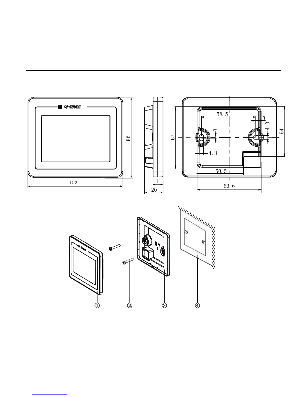
Fig 1.1 Dimension of wired controller
Fig 1.2 Wired controller parts
Page 6
Wired Controller XK55
2
No. 1 2 3 4
Name
Panel of wired
controller
Screw M4X25
Soleplate of wire
controller
Terminal box installed in
the wall
Q’ty 1 2 1 Provided by user
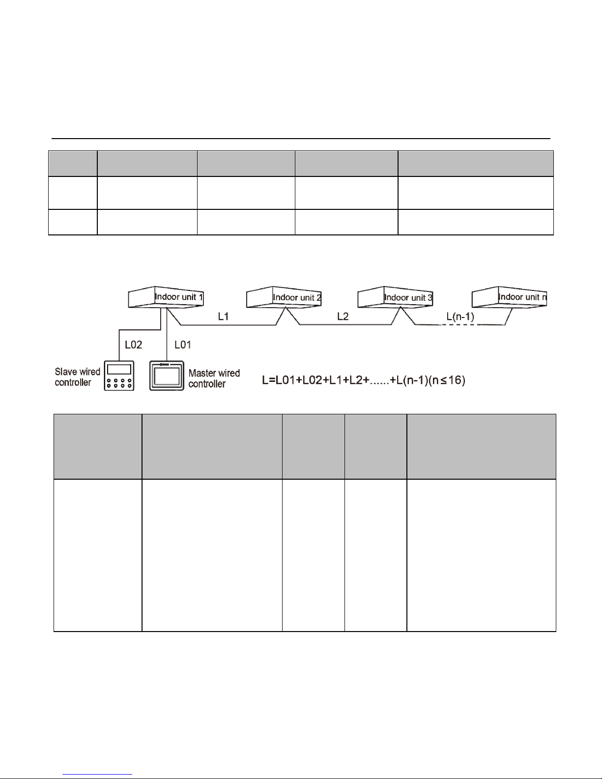
1.1 Selection requirement for communication wire
Fig 1.3 Length of communication wire
Wire material
type
Total length of
communication line
between indoor unit and
wired controller L (m)
Wire
size
(mm2)
Material
standard
Remarks
Light/Ordinary
Polyvinyl
chloride
sheathed
cord. (60227
IEC 52
/60227 IEC
53)
L≤250
2×0.75~
2×1.25
IEC
60227-5:
2007
1. Total length of
communication line can't
exceed 250m.
2. The cord shall be
Circular cord (the cores
shall be twisted together).
3. If unit is installed in
places with intense
magnetic field or strong
interference, it is
necessary to use shielded
wire.
Page 7

Wired Controller XK55
3
Caution:
① If the air conditioner is installed the place with strong magnetic interference,
the communication wire of wired controller must use shielding twisted pair
wire.
② The communication wire of the wired controller must be selected according to
this manual. Prohibit selecting the communication wire which is not comply
with the requirement of this manual.
③ When operating two wire controllers, master wired controller and slave wired
controller can’t be this wire controller.
1.2 Installation requirement
(1). Prohibit installing the wired controller at wet place.
(2). Prohibit installing the wired controller at sunshine place.
(3). Prohibit installing the wired controller at the place where is closing to
high-temperature objects or with splashing water.
(4). Prohibit installing the wired controller at the place where is facing to the
window to prevent the interference from the same model remote controller in
neighbor.
Page 8
Wired Controller XK55
4
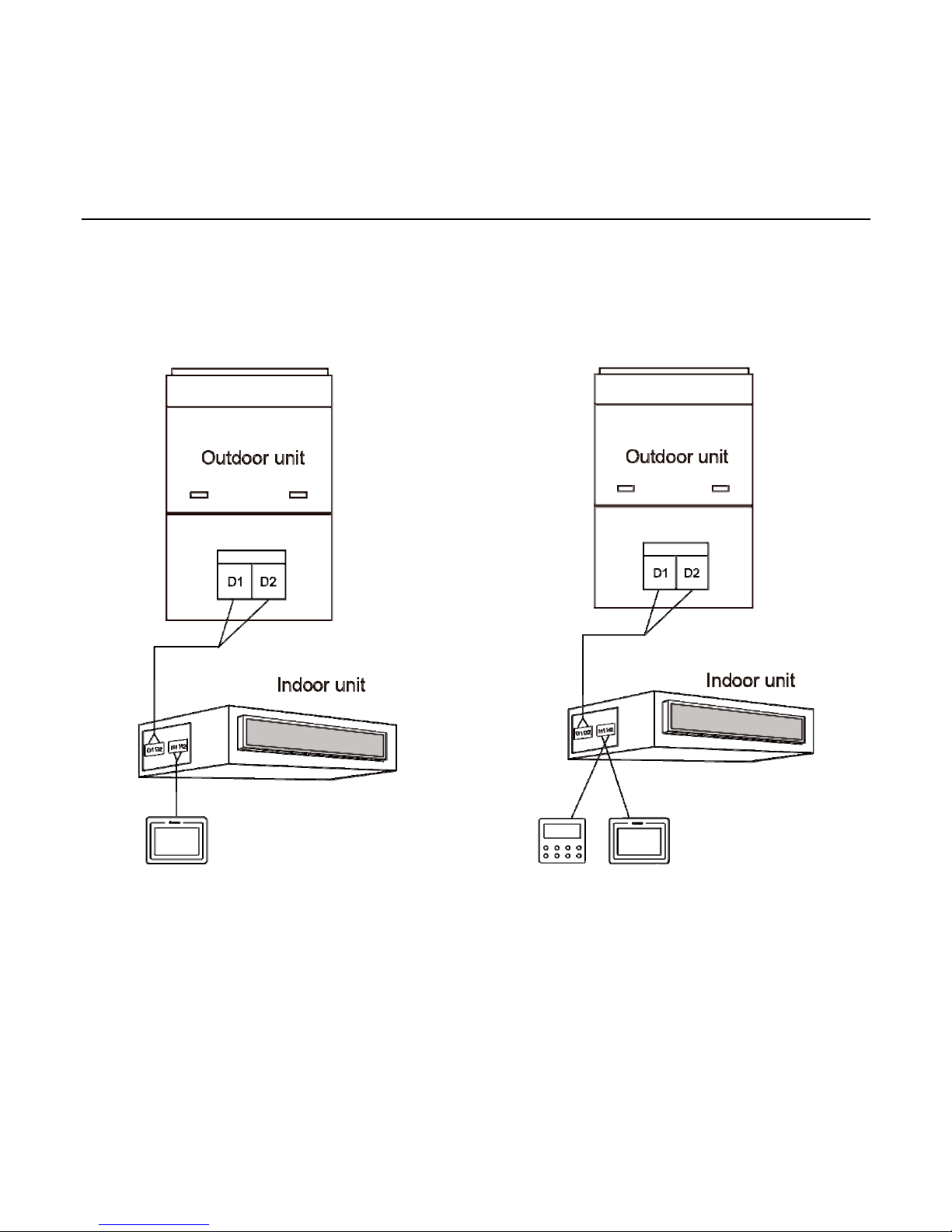
1.3 Wiring requirement
There are four kinds of wiring method for wired controller and indoor unit:
Fig 1.4 One wired controller controls one
indoor unit
Fig 1.5 Two wires controllers control one
indoor unit
Page 9
Wired Controller XK55
5
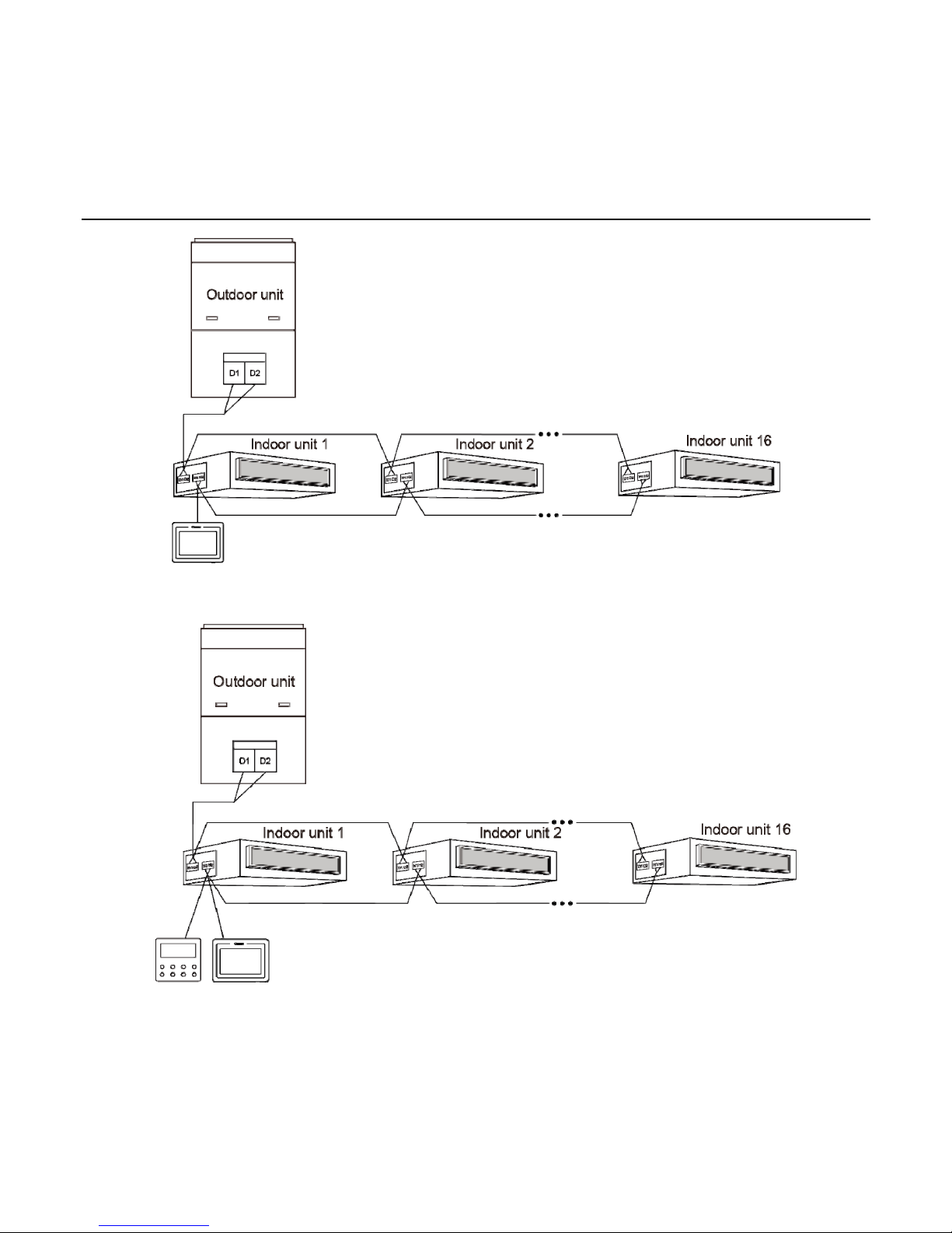
Fig 1.6 One wired controller controls more indoor units simultaneously
Fig 1.7 Two wired controllers control more indoor units simultaneously
Page 10

Wired Controller XK55
6
Wiring instruction:
(1). When one wired controller controls more indoor units at the same time, wired
controller can be connected to any one indoor unit and the connected indoor unit
should be in the same series. The maximum quantity of indoor units controlled by the
wired controller can’t exceed 16 sets and the connected indoor units should be in the
same system. Wired controller should set the Number of IDUs. Please refer to 3.2.12
Engineering Setting Page for the detailed setting method.
(2). When two wired controllers control one indoor unit, the addresses for those
two wired controllers should be different. Please refer to the page of Engineering
Setting for the address of wired controller.
(3). When two wired controllers control more indoor units, the wired controller can
be connected to any one indoor unit. The connected indoor unit should be in the
same series. The addresses for those two wire controllers should be different (set at
3.2.12 Engineering Setting page). The maximum quantity of indoor units controlled
by the wired controller can’t exceed 16 sets and the connected indoor units should be
in the same system. Wired controller should set the Number of IDUs. Please refer to
3.2.12 Engineering Setting Page for the detailed setting method.
(4). When one (or two) wired controller (s) control (s) more indoor units, the
setting for the controlled indoor unit should be the same.
(5). The wiring between wired controller and indoor unit must be according the
wiring method of fig 1.4-1.7. In the wiring method of fig 1.5 and fig 1.7, only one
master wired controller (address 1) and one slave wired controller (address 2) can be
Page 11
Wired Controller XK55
7
set. The quantity of wired controller can’t exceed two.
Note:
Series of indoor units include: ①Common Multi VRF Units; ②Fresh Air Units;
③
Double-heat Sources Units; ④ Combined Units; Except for fresh air units,
double-heat sources units and combined units, the rest of indoor units belong to
common multi VRF units.
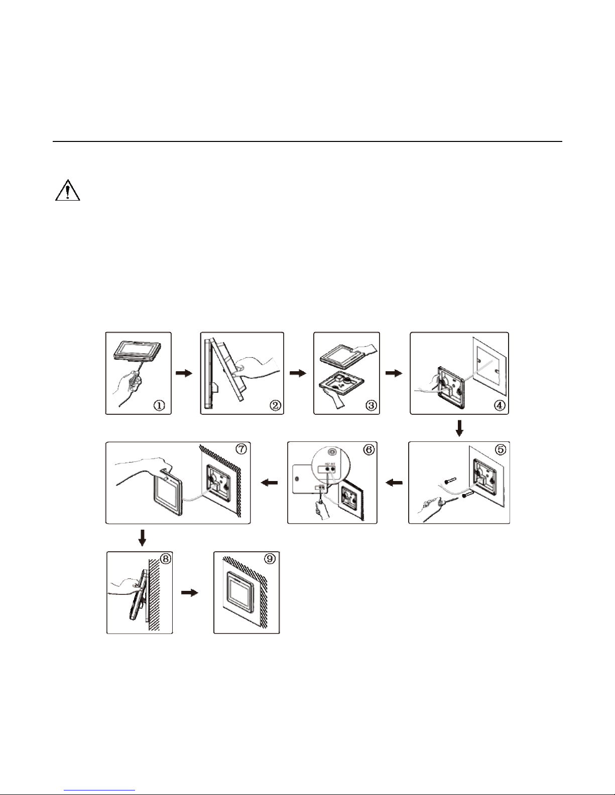
1.4 Installation
Fig 1.8 Installation sketch map of wired controller
Page 12
Wired Controller XK55
8
Please pay attention to below items:
(1). Please disconnect the power support for indoor unit before installation. The
power must be disconnected during the whole installation process.
(2). Pull out the 2-core dual twisted pair wire from the installation hole on wall and
then pull it through the wiring hole at the back of soleplate plate of wired controller.
(3). Stick the soleplate on the wall and then use screw M4X25 to fix sole plate
and installation hole on the wall together.
(4). Connect the two-core twisted pair wire to H1 and H2 wiring terminal and then
tighten screws.
(5). Finally, bind the panel of wired controller and sole plate of wired controller
together.
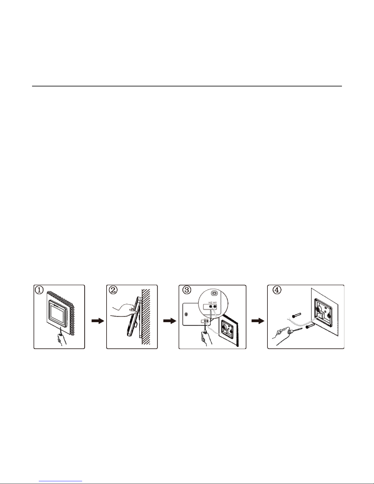
1.5 Disassembly
Fig 1.9 Disassembly sketch map of wired controller
Page 13
Wired Controller XK55
9
2 Display Instruction
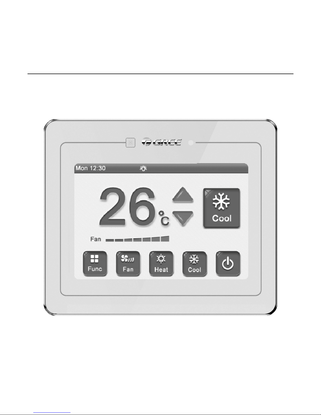
2.1 Outside view
Fig 2.1 Appearance of wired controller
Page 14
Wired Controller XK55
10
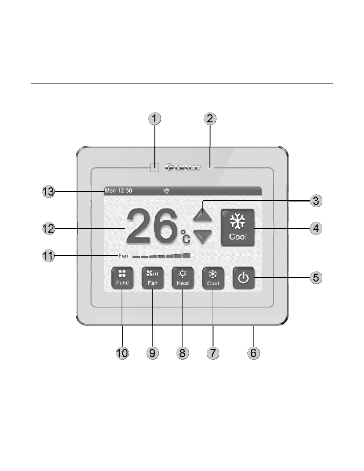
2.2 Buttons instruction
Fig 2.2 Button diagram
Page 15

Wired Controller XK55
11
Button instruction
Number Name Definition
1
Receiving
window of
remote control
signal
It’s used for receiving the signal of remote controller
2
ON/OFF
indicator
Red color indicates the unit is off and white color indicates the
unit is on
3 Temp button It’s used for adjusting operating temperature
4 Mode button It’s used for switching operating mode
5 ON/OFF button It’s used for turning on or turning off the unit
6
Slight touch
button
Short press this button to switch on/off status
Long press this button for 5s to resume touch screen and LCD
7 Cooling button It’s used for selecting cooling mode
8 Heating mode It’s used for selecting heating mode
9 Fan button It’s used for switching fan speed
10 Function button It’s used for entering into next page
11 Status column It’ used for displaying time and starting up functions
12
Temperature
display
It’s used for displaying temperature
13
Fan speed
display
It’s used for display set fan speed
Page 16

Wired Controller XK55
12
2.3 Icon instruction
Mode ( base on the indoor unit)
Display Definition Display Definition
Auto *
Cooling
Dry
Fan
Heating
Floor heating *
3D heating *
Space heating *
Function, status
Display Definition Display Definition
Air *
Gate-control
Clean
Comfort(Reserved
function )
E-heater *
Error
Health *
Defrost
12-drying
Light
Left&right swing *
Master indoor unit
Memory
Absence
Rapid
Quiet
Save
Shield
Slave wired controller
Sleep
Timer
Up&down swing
X-fan
Group control
Page 17

Wired Controller XK55
13
3 Operation Instruction
3.1 Summary
This wired controller adopts 3.5 inch high-resolution lattice liquid crystal display,
with capacitor type touch screen. Meanwhile, it’s with a slightly touch button used for
turning on or turning off the unit, convenient for installation:
(1). Separation of function pages are realized for clear demonstration and high
readability.
(2). Except the homepage column, there’s view page for viewing the operation
status.
(3). It is with multiple timer function. You can set three weekly timers and one
countdown timer simultaneously. Under weekly timer, you can preset unit-on mode,
fan speed, set temperature and repeat days.
(4). You can set backlight time, lightness, language, etc..
(5). When there’s no operation, it will enter into sleep mode automatically, only
ON/OFF indicator is on (white indicator is on when the unit is turned on and the red
indicator is on when the unit is turned off), which can not only save energy, but also
not affect sleep. At the same time, you can also turn on the ON/OFF indicator through
light function.
Page 18

Wired Controller XK55
14
3.2 Page instruction
This wired controller is with clock time display function. For the first operation, if
the system time is different from the current time. You can adjust the time on the
setting page in order to ensure the accuracy of timer operation. Meanwhile, you can
change backlight time, lightness, sound and language according to individual habit.
The instruction for the detailed operation is as below.
3.2.1 Homepage
Unit is turned off Unit is turned on
When turning on the unit, press mode button to switch the mode. After each
pressing of the button, the mode will change in the sequence as below:
Auto-> Cooling-> Dry-> Fan-> Heating-> Floor heating-> 3D heating-> Space
heating-> Auto
Note:
Auto mode is only invalid for the indoor unit under main mode.
Page 19

Wired Controller XK55
15
After turning on the unit, press
▲ ▼ to adjust operating temperature and
the temperature setting range is 16℃~30℃.
Note:
Under auto mode, the temperature adjust button is invalid.
Press ON/OFF button to turn on or turn off the unit.
After turning on the unit, press Fan to select fan speed. After each pressing of
that button, the fan speed will change in below sequence:
Note:
① Under drying mode, the fan speed is defaulted at low speed and it can’t be
adjusted.
② Under floor heating mode, the fan speed is invalid.
Press function button to enter into function page.
Page 20

Wired Controller XK55
16
3.2.2 Function page
Sleep function: Indoor unit will enter into sleeping operation status. It will operate
according to the preset sleeping temperature curve to create comfortable sleeping
ambient for improving sleeping quality.
Absence function: Maintain indoor ambient temperature and keep the rapid
heating after the unit is turned on. Absence function can only started up under
heating mode.
Rapid function: Decrease or increase temperature rapidly to reach to the set
value when turning on the unit for improving comfort. Rapid function can only be
started up under cooling or heating mode.
Swing function: It used to turn on or turn off swing function.
After turning on the unit, press Sleep to turn on or turn off sleep function.
Sleep function is invalid under auto, fan and floor heating mode.
Page 21

Wired Controller XK55
17
When the unit is operating under cooling or heating mode, press Rapid to
start up or turn off rapid function.
After the unit is turned on under heating mode, press Absence to turn on or
turn off absence function. After absence function is started up, the set temperature on
homepage displays 8℃.
After turning on the unit, press Swing to turn on or turn off swing function
(normal swing function).
Press Timer to enter into timer page.
Press More to enter into more functions operation.
Preset Set to enter into set page.
Press View to enter into view page.
Press Back to turn back to previous page.
3.2.3 More function page
Page 22

Wired Controller XK55
18
Quiet function: Reduce the noise of indoor unit. There are two kinds of mode for
quiet function: quiet and auto quiet. Quiet function is not valid under auto, cooling,
drying, fan, heating, 3D heating or space heating mode.
E-heater function*: Under drying mode, auxiliary electric heating is allowed to be
turned on to increase air outlet temperature and improve the comfort. Under heating
or 3D space heating mode, the auxiliary electric heating is allowed to be turned on for
improving heating efficiency. Under heating or 3D space heating mode, turn off the
auxiliary heating to save energy.
Health function*:Turn on or turn off the health function.
Light function:Turn on or turn off the light on indoor unit.
X-fan function:Dry the left water on the evaporator after turning off the unit to
prevent mildew.
12-drying function: it can only be started up under dry mode. The set
temperature on the homepage displays 12℃.
Press ∧ or ∨ to switch functions.
Press corresponding function button to turn on or turn off this function, or
enter into the setting page.
Note:
Operation is not available for the light black items, which indicates this
function is invalid, such as the icon of E-heater.
Page 23

Wired Controller XK55
19
3.2.4 Air function page*
Air function: Improve air quality through adjust indoor fresh air volume.
Press ON to turn on or turn off the air function.
Press ◀ ▶ to set the air grade.
Page 24

Wired Controller XK55
20
3.2.5 Save function page
Save function: Set temperature lower limit under cooling or drying mode or
temperature upper limit for heating or 3D heating or space heating mode to let the air
conditioner operate at appointed temperature range for saving energy.
Press ON to turn on or turn off save function.
Press ◀ ▶ to adjust the limit temperature.
Press save mode to switch different kinds of mode.
Page 25

Wired Controller XK55
21
3.2.6 Fix-angle swing page
Fixed-angle swing function:It used for setting the swing position for up&down
swing or left&right swing.
Press U & D to switch up&down swing.
Press L & R to switch left&right swing.
Press your required swing position to start up corresponding swing function.
Page 26

Wired Controller XK55
22
3.2.7 Filter cleaning page
The prompting function for filter cleaning: The air conditioning unit can record its
operation time. When it is at setting time, it will remind the user to clean filter so as to
avoid filth blockage of filter without cleaning for a long time. The filth blockage of filter
will lead to bad effect of cooling and heating function, abnormal protection and
bacteria-collecting, etc.
The prompting time for cleaning varies from different cleaning degree of current
ambient and cleaning frequency. The following four conditions are classified as:
(1). Not set cleaning alarm function and the start button won’t be bright.
(2). Slight pollution (A): when the cleaning frequency is “0”, it represents its
accumulative operation time is 5500 hours. For every “1” increases, the accumulative
operation time adds 500 hours. When the cleaning frequency is “9”, the accumulative
operation time is 10000 hours.
Page 27

Wired Controller XK55
23
(3). Moderate pollution (B): when the cleaning frequency is “0”, it represents its
accumulative operation time is 1400 hours. For every “1” increases, the accumulative
operation time adds 400 hours. When the cleaning frequency is “9”, the accumulative
operation time is 5000 hours.
(4). Severe pollution (C): when the cleaning frequency is “0”, it represents its
accumulative operation time is 100 hours. For every “1” increases, the accumulative
operation time adds 100 hours. When the cleaning frequency is “9”, the accumulative
operation time is 1000 hours.
Click Current Cleanliness to enter the setting of cleaning degree.
Click Cleaning Cycle to enter frequency setting.
Click ON to turn on or turn off filter cleaning function.
3.2.8 Timer function page
Page 28

Wired Controller XK55
24
The timer can be set whenever the unit is turned on or turned off. Three weekly
timers and one countdown timer can be chosen freely.
In order to maintain the accuracy of time, please check the system time whether
to be the current time before setting up timing. If the system time is incorrect, reset it
in the date and time.
Click Timer * to enter the corresponding timer setting page.
Click
to open or close the corresponding timing.
Click ◀ ▶ to adjust the timing for count down.
Click Back to return to the previous page.
Click Home to directly return to homepage.
3.2.9 Weekly timer setting page
Page 29

Wired Controller XK55
25
Timer 1, 2, 3 is the weekly timer. We can set the mode, setting temperature, fan
speed and repeat days when setting the function of timer on. If you want to set timer
on/timer off, you can only have to activate the time of turn on/timer off; If you want the
timer on and timer off are valid simultaneously, you can activate the time for timer on
and timer off. If you want the timer is valid in appointed days, you can select the days
in Repeat.
Click On Time* to set the timer for turning on the unit.
Click Off Time* to set the timer for turning off the unit.
Click
to turn on or turn off the relevant options.
Click ▲ ▼ to set the temperature when turn on the unit.
Click Mode to set the mode when turn on the unit.
Click Fan to set the speed when turn on the unit.
Click OK to save current timer setting and return to the previous page.
Click Cancel, it will not save the setting and directly return to previous page.
Click Repeat to set repeat days (shown as below):
Page 30

Wired Controller XK55
26
In this case, you can tick the days for repeat operation.
3.2.10 Time setting page
Page 31

Wired Controller XK55
27
It is used for setting hour and second individually and show the current value
through the display so as to read conveniently.
Click * Hour to set the accurate hour.
Click * Minute to set the accurate minute.
Click ◀ ▶ to adjust the number value.
If it belongs to a 12-hour clock. Click forenoon to choose afternoon, otherwise
or not.
3.2.11 Setting page
It is used for setting the personalize function and content of engineering
debugging.
Click the corresponding setting items to enter the setting page of this
function.
Page 32

Wired Controller XK55
28
3.2.12 Engineering setting page
It is used for engineering debugging.
Click the Master Wired Controller for turning up or turn off the master wired
controller function.
Click the Master IDU for turning up the indoor units function of main mode.
Click Parameter View to enter the parameter inquiry page.
Click Parameter Setting to enter the parameter setting page.
Note:
The parameter setting is valid only if the master controller turns on.
Page 33

Wired Controller XK55
29
Introduction on each setting parameter
Setting items Setting scope Acquiesce Remarks
High Ceiling
Installation
Turn on, turn
off
turn off Only applicable to cassette units
Prior Operation
Turn on, turn
off
turn off
If the power supply is not enough, we
permit giving priority on operation of
indoor units to turn on/off. Other indoor
units will turn off compulsively.
Use Remoter
Turn on, turn
off
turn on
Link with Fresh Air
IDU*
Turn on, turn
off
turn off
After setting linkage function, the new
duct indoor unit will turn on or turn off
automatically according to the turn
on/off of ordinary indoor units,
meanwhile we can turn on/off
manually.
Note:
It is only applicable for new duct
indoor units.
Indoor Fan Static
Pressure
1~9 5
5 speed:3、4、5、6、7
9 speed:1、2、3、4、5、6、7、8、9
Number of IDUs
0: this function
is forbidden
1-16:
Numbers of
indoor units
1
Set the relevant value according to the
number of indoor unit received.
Page 34

Wired Controller XK55
30
Angle of Air Return
Board
Angle 1
Angle 2
Angle 3
Angle 1
Only applicable to units with Air Return
Board.
Auto Temp
Automatic
cooling
:
17
℃~30℃
Automatic
heating
:
16
℃~29℃
Automatic
cooling
:
25℃
Automatic
heating
:
20℃
Cooling setting temperature - Heating
setting temperature≥1.
Clear Filter Cleaning
Time
Clear, not
clear
not clear
Fresh Air IDU Output
Temp*
cooling:16
℃
~30℃
heating:16
℃
~30℃
cooling
:
18℃
heating
:
22℃
It is only applicable for new duct indoor
units.
Note:
After entering the parameter setting page, the remote controller signal is
invalid.
Page 35

Wired Controller XK55
31
Introduction for parameters view
Parameter name Display scope Parameter name Display scope
Number of IDUs 1~16 Filter Dirty Alarm Actual value
Cool & Heat Modes
cool only, heat
only, cool & heat,
fan
Max Distribution
Ratio
135%、150%、110%
Master IDU's Project No. 1~255
Wired Controller's
Address
1、2
Online IDUs 1~80 CAN2 Address 1~255
Error IDU Location & IDU
Project No.
1~255 IDU Error Log 5 historical defaults
IDU Capacity Actual value Prior Operation Yes, no
EXV Status 0~20
View All IDU Project
No.
1~255
Room Temp
-9~99℃
Inlet Temp
-9~99℃
Outlet Temp
-9~99℃
Relative Humidity Actual value
Fresh Air IDU Output
Temp
Actual value
ODU Static
Pressure Setting
0、20、50、80
ODU Error Log
5 historical
defaults
The following parameter can be viewed only if the master wired controller is turned on .
Unit Code
0~9,A~Z,a~z,-
Main Board Code
0~9,A~Z,a~z,-
Module HP
-40~70℃
Module LP
-69~38℃
Outdoor Temp
-30~139℃
Defrosting Temp
-30~139℃
Page 36

Wired Controller XK55
32
Oil Return Temp
-30~139℃
Separator Outlet
Temp
-30~139℃
ODU Heat EXV1 0~48 ODU Heat EXV2 0~48
Subcooler EXV 0~48
Subcooler Liquid
Temp
-30~139℃
ODU Fan Operation Freq 0~100Hz
Comp1 Operation
Freq
0~200Hz
Comp2 Operation Freq 0~200Hz
Comp3 Operation
Freq
0~200Hz
Comp1 Discharge Temp
-30~150℃
Comp2 Discharge
Temp
-30~150℃
Comp3 Discharge Temp
-30~150℃
Comp4 Discharge
Temp
-30~150℃
Comp5 Discharge Temp
-30~150℃
Comp6 Discharge
Temp
-30~150℃
Condenser Inlet Temp
-30~139℃
Condenser Outlet
Temp
-30~139℃
Note:
After entering the parameter viewing page, the remote controller signal is
invalid.
Page 37

Wired Controller XK55
33
3.2.13 View page
It is used for displaying the current operation function so as to let you learn the
units status at the first time.
Press ∧ or ∨ to switch page.
4 Special function explanation
4.1 Remote shield function
Remote shield function: Remote control or integrated controller can shield the
remote control of relevant function of wired controller or button operation. Its
operation is invalid so as to realize the function of remote control.
Remote shield function is divided into whole shield and partial shield. When it is
whole shield, the operation towards remote control of wired controller or button
Page 38

Wired Controller XK55
34
operation are invalid. When it is partial shield, the operation towards remote control of
conductively-closed function of wired controller or button operation are invalid.
When remote control or integrated controller is conducting remote shield towards
wire controller, the main page status bar will display
. When the user is conducting
remote control or key button operation towards wire controller, it indicates the
operation is invalid.
4.2 Entrance guard display function
When there is access control system, the wired controller has the functions that if
you insert card, it will begin operation and if you pull out the card, it will stop operation.
After pulling out, it will memorize and restore the work if you insert the card again. If
you do not insert the card (or imperfect contact of the card), the symbol for pulling out
the card will be displayed, neither remote control nor operation of wired
controller will be effective and icon
will be flickering.
Note:
This model cannot be connected with gate control system on its own
because it cannot detect gate control signal directly. To realize gate control display
and gate control function, it has to be used with wired controller that includes gate
control signal detecting function (used as master and salve wired controller).
Page 39

Wired Controller XK55
35
5 Abnormal code
When there is any abnormalities occur during system operation, the main
interface of wired controller will show multifunction icon
, the specific code and
indoor units located so as to let you understand the operation status of air conditioner
at first time.
Note:
Please turn off the unit when malfunction occur and ask for profession
staff for maintenance.
5.1 Code table for outdoor units malfunction
Code content Code content Code content
E0
Outdoor units
malfunction
FP
Malfunction of DC
motor
b4
Subcooler liquid
outlet temperature
sensor malfunction
E1
High pressure
protection
FU
Shell roof
temperature
sensor malfunction
of compressor 1
b5
Subcooler air
outlet temperature
sensor malfunction
E2
Discharge low
temperature
protection
Fb
Shell roof
temperature
sensor malfunction
of compressor 2
b6
Steam split inlet
temperature
sensor malfunction
E3
Low pressure
protection
J1
Overcurrent
protection of
compressor 1
b7
Steam split outlet
temperature
sensor malfunction
E4
High discharge
temperature
protection of
compressor
J2
Overcurrent
protection of
compressor 2
b8
Outdoor
temperature
sensor malfunction
Page 40

Wired Controller XK55
36
F0
Imperfect main
board of outdoor
units
J3
Overcurrent
protection of
compressor 3
b9
Heat exchanger air
outlet temperature
sensor malfunction
F1
High pressure
sensor malfunction
J4
Overcurrent
protection of
compressor 4
bA
Oil return
temperature
sensor malfunction
F3
Low pressure
sensor malfunction
J5
Overcurrent
protection of
compressor 5
bH
Systematic hour
abnormality
F5
Discharge
temperature
sensor malfunction
of compressor 1
J6
Overcurrent
protection of
compressor 6
bC
Shell roof
temperature
sensor abscission
protection of
compressor 1
F6
Discharge
temperature
sensor malfunction
of compressor 2
J7
Back flow
protection of
four-way valve
bL
Shell roof
temperature
sensor abscission
protection of
compressor 2
F7
Discharge
temperature
sensor malfunction
of compressor 3
J8
High systematic
pressure ratio
protection
bE
Malfunction of inlet
tube temperature
sensor of
condenser
F8
Discharge
temperature
sensor malfunction
of compressor 4
J9
Low systematic
pressure ratio
protection
bF
Malfunction of
outlet tube
temperature
sensor of
condenser
F9
Discharge
temperature
sensor malfunction
of compressor 5
JA Abnormal pressure bJ
High and low
pressure sensors
are connected
inversely
FA
Discharge
temperature
sensor malfunction
of compressor 6
JC
Water switch
protection
P0
Driver board
malfunction of
compressor
Page 41

Wired Controller XK55
37
FH
Current sensor
abnormality of
compressor 1
JL
Protection
because high
pressure is too low
P1
Driver board
abnormality of
compressor
FC
Current sensor
abnormality of
compressor 2
JE
Oil return pipe is
blocked
P2
Supply voltage
protection of
compressor driver
board
FL
Current sensor
abnormality of
compressor 3
JF
Oil return pipe is
leaking
P3
Restoration
protection of
compressor driver
module
FE
Current sensor
abnormality of
compressor 4
b1
Outdoor ambient
temperature
sensor malfunction
H0
Fan driver board
malfunction
FF
Current sensor
abnormality of
compressor 5
b2
Defrosting
temperature
sensor 1
malfunction
H1
Fan driver board
operation
abnormality
FJ
Current sensor
abnormality of
compressor 6
b3
Defrosting
temperature
sensor 2
malfunction
H2
Supply voltage
protection of fan
driver board
Page 42

Wired Controller XK55
38
5.2 Code table for indoor unit malfunction
Code Content Code Content Code Content
L0
Indoor unit
malfunction
LA
Inconsistent series
of indoor units for
one controlling
multiple units
d7
Humidity sensor
malfunction
L1
Indoor fan
protection
LH
Severe turbidity of
air quality alarm
d8
Water temperature
sensor malfunction
L2
Auxiliary heating
protection
LC
Mismatching of
indoor and outdoor
units’ model
d9
Jumper
malfunction
L3
Water full
protection
LP
PG motor
zero-crossing
malfunction
dA
Indoor unit
network address
abnormality
L4
Wired Controller
Power Supply
Error
d1
Imperfect indoor
circuit board
dH
Circuit board
abnormality of wire
controller
L5
Freeze prevention
protection
d3
Ambient
temperature
sensor malfunction
dC
Setting
abnormality of
capacity dial-up
L7
Lacking master
indoor unit
d4
Inlet temperature
sensor malfunction
dL
Air outlet
temperature
sensor malfunction
L8
Insufficient power
supply
d5
Malfunction of
middle tube
temperature
sensor
dE
Indoor CO2 sensor
malfunction
L9
Inconsistent
number of indoor
units for
one-to-more units
d6
Outlet temperature
sensor malfunction
db
Special code:
engineering
debugging code
Page 43

Wired Controller XK55
39
5.3 Code table for debugging
Code Content Code Content
Cod
e
Content
U2
Outdoor units
Capacity
Code/Setting of
jumper is wrong
UE
Invalid charge of
refrigerant
CH
High rating
capacity
configuration
U3
Phase protection of
power supply
UL
Dial-up error for
emergent operation of
compressor
CL
Low rating
capacity
configuration
U4
Protection of lack
of Refrigerant
C0
Communication
malfunction between
indoor unit and outdoor
unit, indoor unit and
wired controller
CF
Malfunction of
multiple master
units
U5
The address for
drive board of
compressor is
wrong
C2
Communication
malfunction of master
controller and the driver
of inverter compressor
CJ
Dial-up conflict
of systematic
address
U6
Alarm due to
abnormity of valve
C3
Drive communication
malfunction between
master control and
inverter and inverter fan
CP
Malfunction of
multiple master
wired controller
U8
Malfunction of
pipeline of indoor
unit
C4
Indoor units deficiency
malfunction
CU
Communication
malfunction
between indoor
units and
received lamp
panel
U9
Malfunction of
pipeline of outdoor
unit
C5
Number conflict of
indoor units engineering
alarm
Cb
Address
overflow of units
IP
UC
Setting
successfully for
main indoor units
C6
Inconsistency of outdoor
units number alarm
Page 44

Wired Controller XK55
40
5.4 Code table for state
Code Content Code Content
A0 Unit is on standby for debugging AU
Long-distance stop operation
due to emergency
A1
Inquiry on operation parameter of
press
Ab
Stop operation due to
emergency status
A2
Recovery operation of refrigerant
after sales
Ad Limited operation
A3 Defrosting An
High temperature prevention
control
A4 Oil return n3 Compulsory defrosting
A5 Online test n5
Engineering series number of
indoor unit is deviated
A8 Vacuum pumping mode nL
Target low pressure
modification
AH Heating nJ
High temperature prevention
under heating mode
AC Cooling nP
Defrosting temperature
adjustable value
AF Fan nU
Clean the long-distance
shielding order of indoor unit
AJ Cleaning warning
Page 45

GREE ELECTRIC APPLIANCES, INC. OF ZHUHAI
Add: West Jinji Rd, Qianshan, Zhuhai, Guangdong, China, 519070
Tel: (+86-756) 8522218 Fax: (+86-756) 8669426
E-mail: gree@gree.com.cn www.gree.com
 Loading...