

Gree XK49 Owner's Manual
Owner's Manual
Commercial Air Conditioners
●Thank you for choosing Commercial Air Conditioners ,please read this owner’s manual carefully before
operation and retain it for future reference.
●GREE reserves the right to interpret this manual which will be subject to any change due to product
improvement without further notice.
●GREE Electric Appliances, Inc. of Zhuhai reserves the final right to interpret this manual.
Wired Controller XK49

User Notices
◆The power supply for all indoor units must be unified.
◆Prohibit installing the wired controller at wet or sunshine places.
◆Do not knock, throw or frequently disassemble the wired controller.
◆Do not operate the wired controller with wet hands.
◆In one system network, you must set one indoor unit as the master indoor unit,
Other indoor units are slave indoor units .
◆The operation mode of the system is basing on that of master indoor unit. Master
indoor unit can switch to any modes, while slave unit can’t switch to the mode that is
conflicting with master indoor unit.
◆When master indoor unit changes mode which cause operation mode of
slave indoor unit conflicts with that of system, the operation mode of slave unit will
switch to the operate mode of system automatically.
◆When two wired controllers control one (or more) indoor unit(s), the address of
wired controller should be different.
◆This wired controller should be set as slave controller when it is used to control
one (multiple) indoor unit (s) with other types of wired controller (s).
◆This wired controller is equipped with gate control interface, which can be
connected with gate control system to switch unit on/off by inserting or removing a card.
◆Functions with “*” are optional for indoor units. If a function is not included in an
indoor unit, wired controller can’t set the function, or setting of this function is invalid to
the indoor unit.

CONTENTS
1. DISPLAY ................................................................................................................. 1
1.1 LCD OF WIRED CONTROLLER ........................................................................... 1
1.2 LCD DISPLAY INSTRUCTION .............................................................................. 2
2. BUTTONS ............................................................................................................... 3
2.1 BUTTON GRAPHICS ............................................................................................ 3
2.2 FUNCTION INSTRUCTION OF BUTTONS .............................................................. 3
3. INSTALLATION AND COMMISSIONING .......................................................... 3
3.1 INSTALLATION OF WIRED CONTROLLER ............................................................ 4
3.1.1 Communication Line Selection .............................................................. 4
3.1.2 Installation requirements......................................................................... 5
3.1.3 Wiring Requirements ............................................................................... 5
3.1.4 Installation ............................................................................................... 10
3.1.5 Disassembly ........................................................................................... 11
3.2 COMMISSIONING .............................................................................................. 11
3.2.1 Set Master Indoor Unit .......................................................................... 11
3.2.2 Parameter Enquiry ................................................................................. 11
3.2.3 Parameter Setting .................................................................................. 15
4. OPERATION INSTRUCTIONS................................................................ .......... 17
4.1 ON/OFF ............................................................................................................ 17
4.2 MODE SETTING ................................................................................................ 17
4.3 TEMPERATURE SETTING .................................................................................. 18
4.4 FAN SETTING.................................................................................................... 18
4.5 SWING SETTING ............................................................................................... 19
4.6 REMOTE SHIELD FUNCTION............................................................................. 19
4.7 CHILD LOCK FUNCTION ................................................................................... 19
4.8 GATE-CONTROL FUNCTION .............................................................................. 19
5. ERROR DISPLAY ................................................................................................ 19
5.1 TABLE OF ERROR CODES FOR OUTDOOR UNIT .............................................. 20
5.2 TABLE OF ERROR CODES FOR INDOOR UNIT ................................ .................. 22
5.3 TABLE OF STATUS CODES ................................................................................ 22
5.4 TABLE OF DEBUGGING CODES ........................................................................ 23
Wired Controller XK49
1
1. DISPLAY
Fig. 1.1 Appearance of wired controller
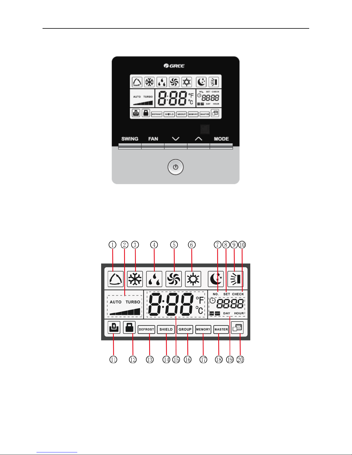
1.1 LCD of Wired Controller
Fig. 1.2 LCD graphics of wired controller
Wired Controller XK49
2
1.2 LCD Display Instruction
Table 1.1 LCD display instruction
No.
Symbols
Instructions
1
*
Auto mode (Under Auto mode, the indoor units will automatically select their
operating mode as per the temperature change so as to make the ambient
comfortable.)
2
Current set fan speed (including auto, low speed, medium-low speed, medium
speed, medium-high speed, high speed and turbo seven status)
3 Cooling mode
4 Dry mode
5 Fan mode
6 Heating mode
7 When inquiring or setting project number of indoor unit, it displays "NO." icon
8 Display "SET" icon under parameter setting interface
9 Up and down swing function
10 Display "CHECK" icon under parameter view interface
11 Gate-control function
12 Child Lock status
13 Outdoor unit defrosting status
14 Shielding status
15
It shows the setting temperature value(In case the wired controller is controlling a
Fresh Air Indoor Unit, then the temperature zone will display FAP)
16 One wired controller controls multiple indoor units
17
Memory status (The indoor unit resumes the original setting state after power
failure and then power recovery)
18 Current wired controller connects master indoor unit
19 The data display area will help to show the parameters checked or set.
20
It indicates the current wired controller is the slave wired controller
(address of wired controller is 02)
Wired Controller XK49
3
2. BUTTONS
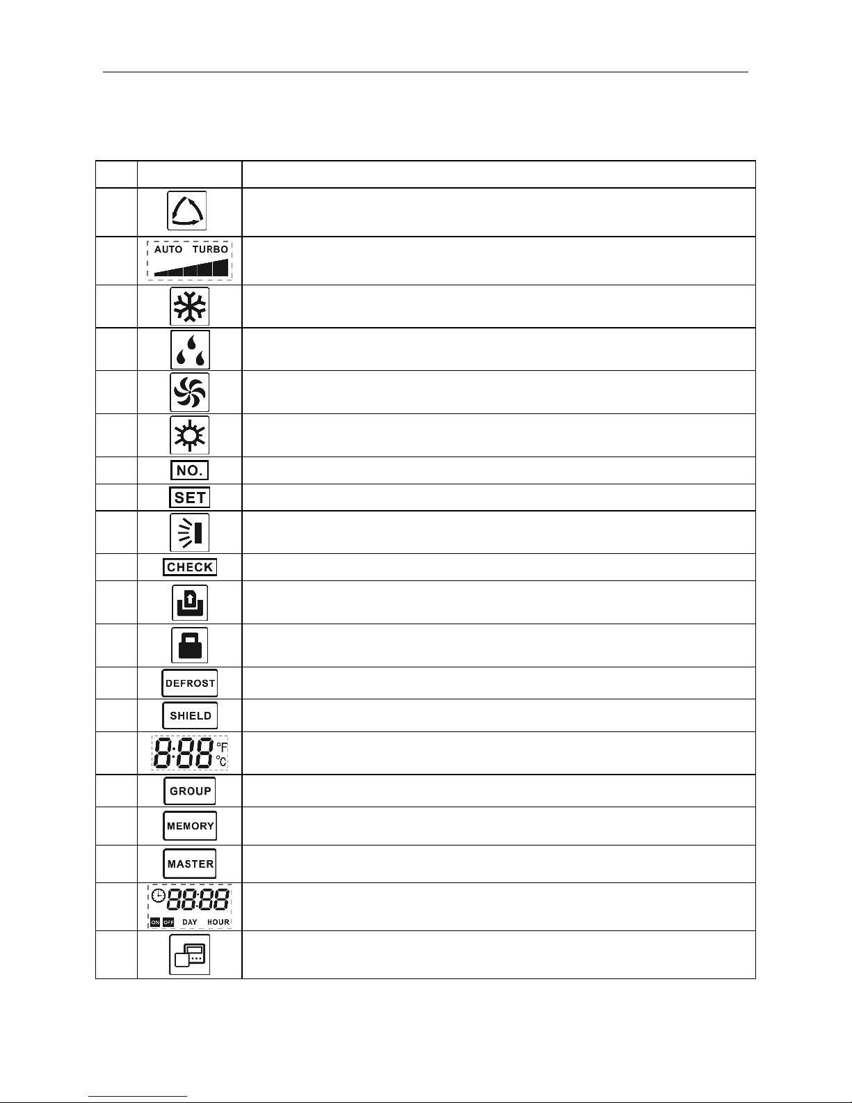
2.1 Button Graphics
Fig. 2.1 Button graphics
2.2 Function Instruction of Buttons
Table 2.1 Function instruction of buttons
No.
Buttons
Instructions
1
SWING
It’s used to set swing status.
2
FAN
Switch among auto, low speed, low-medium speed, medium speed, medium-high
speed, high speed and turbo status
3
ON/OFF
Indoor unit On/Off
4
(1) Set operating temperature of indoor unit
(2) Set and inquiry parameter
5
6
MODE
Switch Auto, Cooling, Dry, Fan, Heating modes for indoor unit. (Note: The Floor
Heating, 3D Heating and Space Heating function icon will show up when the unit
has those functions.)
4+5
+
Simultaneously press “ ” and “ ” for 5s to enter or cancel the Child Lock
function.
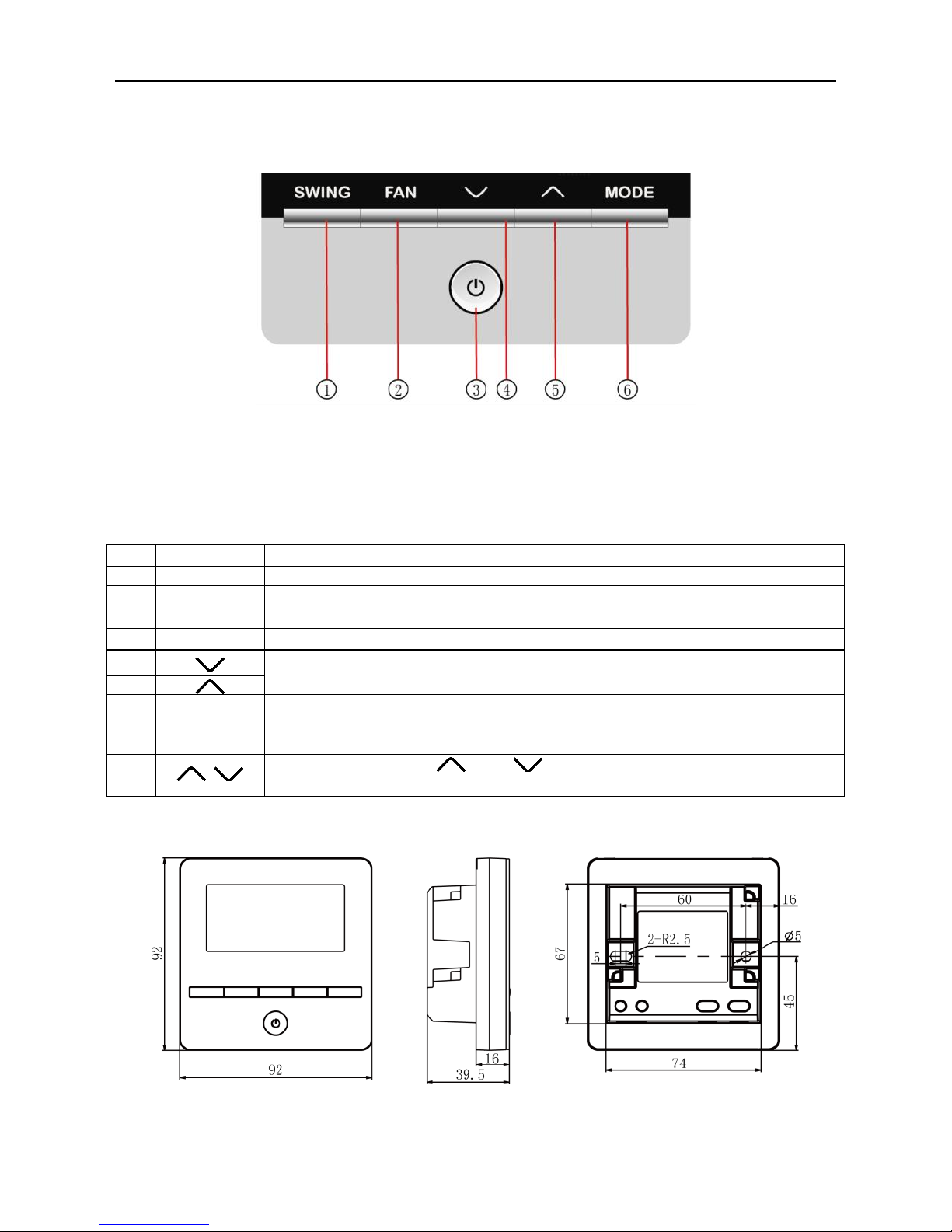
3. INSTALLATION AND COMMISSIONING
Fig. 3.1 Dimension of wired controller
Wired Controller XK49
4
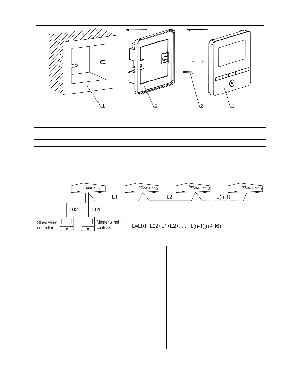
Fig. 3.2 Parts of wired controller
No.
1
2 3 4
Name
Junction box embedded in
the wall
Soleplate of wired
controller
Screw
M4*25
Panel of wired
controller
Q'ty
User-supplied
1 2 1
3.1 Installation of Wired Controller
3.1.1 Communication Line Selection
Fig. 3.3 Length of communication line
Wire material
type
Total length of
communication line
between indoor unit and
wired controller L (m)
Wire size
(mm2)
Material
standard
Remarks
Light/Ordinary
polyvinyl
chloride
sheathed
cord.
(60227 IEC
52
/60227 IEC
53)
L≤250
2×0.75~2×
1.25
IEC
60227-5:2007
1.Total length of
communication
line can't exceed 250m
2.The cord shall be
Circular cord (the
cores shall be twisted
together).
3.If unit is installed in
places with intense
magnetic field or
strong interference, it
is necessary to use
shielded wire.
Wired Controller XK49
5
Note:
①
If the air conditioner is installed at the strong electromagnetic interference place,
communication line of the wired controller must use shielding twisted pair.
②
Materials of communication line for wired controller must be selected according
to this instruction manual strictly.
3.1.2 Installation requirements
(1) Prohibit installing the wired controller at wet places.
(2) Prohibit installing the wired controller at direct sunshine places.
(3) Prohibit installing the wired controller at the place near high temperature
objects or water-splashing places.
(4) Prohibit installing the wired controller at the place where faces forward to the
window. Prevent abnormal work due to the interference from the other wired controller
around.
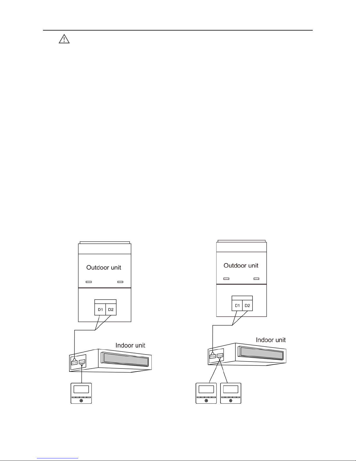
3.1.3 Wiring Requirements
3.1.3.1 Wiring between wired controller and indoor network
There are four network wiring methods between wired controller and indoor unit:
Fig. 3.4 One wired controller controls Fig. 3.5 Two wired controllers
one indoor unit control one indoor unit
Wired Controller XK49
6
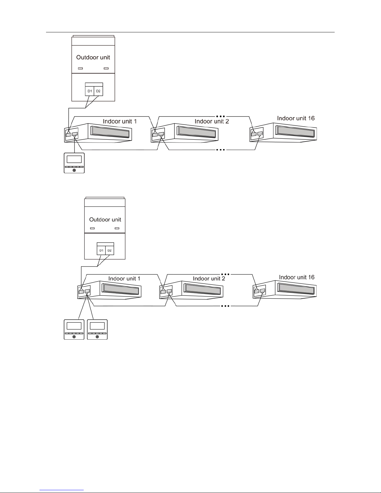
Fig. 3.6 One wired controller controls multiple indoor units simultaneously
Fig. 3.7 Two wired controllers control multiple indoor units simultaneously
Wiring instructions:
(1) When one wired controller controls multiple indoor units simultaneously, the
wired controller can connect to any one indoor unit, but the connected indoor unit must
be the same series indoor unit. The total quantity of indoor unit controlled by wired
controller can't exceed 16 sets, and the connected indoor unit must be within the same
indoor unit's network. Wire controller must set quantity of group control indoor units.
Please refer to 3.2.3 Parameters Setting.
(2) When two wired controllers control one indoor unit, the addresses of those
 Loading...