

Gree XK46 Owner's Manual
Change for life
Wired Controller XK46
Owner's Manual
Commercial Air Conditioners
Thank you for choosing Commercial Air Conditioners ,please read this owner’s manual
carefully before operation and retain it for future reference.
GREE reserves the right to interpret this manual which will be subject to any change due
to product improvement without further notice.
GREE Electric Appliances, Inc. of Zhuhai reserves the nal right to interpret this manual.

User Notices
◆
The power supply for all indoor units must be unied.
◆
Prohibit installing the wired controller at wet or sunshine places.
◆
Do not knock, throw or frequently disassemble the wired controller.
◆
Do not operate the wired controller with wet hands.
◆
In one system network, you must set one indoor unit as the master indoor
unit.
◆
When two wired controllers control one (or more) indoor unit(s), the
address of wired controller should be different.

CONTENTS
1 DISPLAY ...............................................................................................1
1.1 LCD of Wired Controller ............................................................................. 1
1.2 LCD Display Instruction .............................................................................. 2
2. BUTTONS ...........................................................................................4
2.1 Button Graphics .......................................................................................... 4
2.1 Function Instruction of Buttons .................................................................. 4
3. INSTALLATION AND COMMISSIONING ...........................................5
3.1 Installation of Wired Controller ................................................................... 5
3.2 Commissioning ........................................................................................... 9
4. OPERATION INSTRUCTIONS ..........................................................12
4.1 On/Off ....................................................................................................... 12
4.2 Mode Setting ............................................................................................ 12
4.3 Temperature Setting ................................................................................. 13
4.4 Fan Setting ............................................................................................... 13
4.5 Timer Setting ............................................................................................13
4.6 Swing Setting ........................................................................................... 16
4.7 Quiet Setting ............................................................................................. 16
4.8 Sleep Setting ............................................................................................ 17
4.9 Air Setting ................................................................................................. 18
4.10 Light On/Off Setting ................................................................................ 19
4.11 Save Setting ........................................................................................... 19

4.12 Filter Clean Reminder Setting ................................................................ 21
4.13 X-fan Setting ........................................................................................... 22
4.14 Out Setting ............................................................................................. 22
4.15 Remote Shield Function ......................................................................... 22
4.16 Child Lock Function ................................................................................ 23
4.17 Gate-control Function ............................................................................. 23
5. ERROR DISPLAY ..............................................................................23
5.1 Table of Error Codes for Outdoor Unit ...................................................... 24
5.2 Table of Error Codes for Indoor Unit ......................................................... 25
5.3 Table of Status Codes ..............................................................................25
5.4 Table of Debugging Codes .......................................................................26
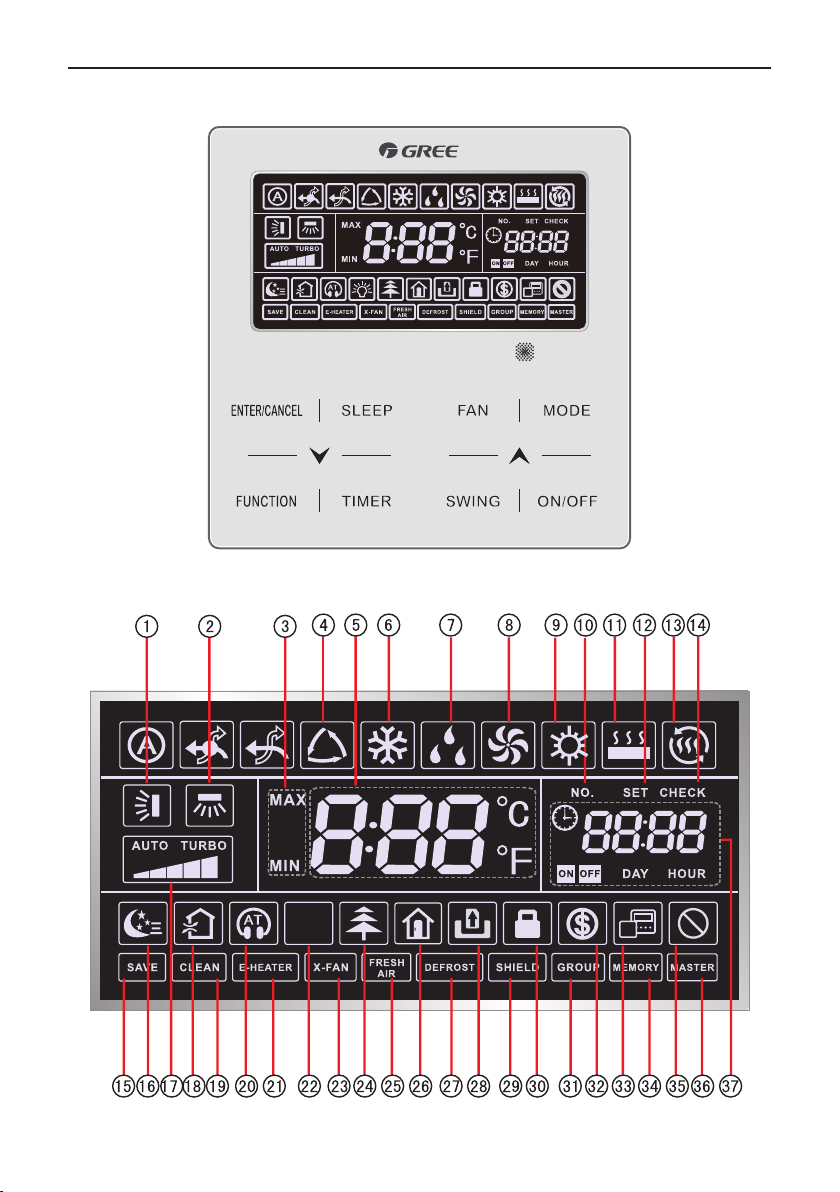
1 DISPLAY
Fig. 1.1 Appearance of wired controller
1.1 LCD of Wired Controller
Wired Controller XK46
Fig. 1.2 LCD graphics of wired controller
1
Wired Controller XK46
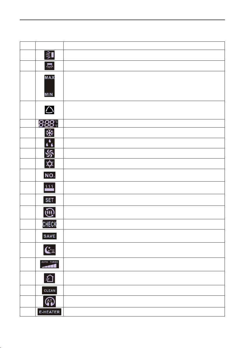
1.2 LCD Display Instruction
Table 1.1 LCD display instruction
No. Symbols Instructions
1 Up and down swing function
2 Left and right swing function
It's valid under Save mode and displays during setting process.
Temperature lower limit for Cooling: Limit the minimum temperature value under
3
4
5 It shows the setting temperature value
6 Cooling mode
7 Dry mode
8 Fan mode
9 Heating mode
10 When inquiring or setting project number of indoor unit, it displays "NO." icon
11
12 Display "SET" icon under parameter setting interface
Cooling or Dry mode.
Temperature upper limit for Heating: Limit the maximum temperature value
under Heating, Floor Heating, Space Heating or 3D Heating mode.
Auto mode (Under Auto mode, the indoor units will automatically select their
operating mode as per the temperature change so as to make the ambient
comfortable.)
Floor Heating mode (When Heating and Floor Heating simultaneously shows
up, it indicates 3D Heating is activated.)
13 Space Heating mode
14 Display "CHECK" icon under parameter view interface
15
16 Sleep status
17
18 Air status
19 Remind to clean the lter
20 Quiet status (including Quiet and Auto Quiet two status)
21 Allow auxiliary electric heating On icon
Outdoor unit operates under Save mode/upper limit of system capacitor less
100%/remote Save status
Current set fan speed (including auto, low speed, medium-low speed, medium
speed, medium-high speed, high speed and turbo seven status)
2
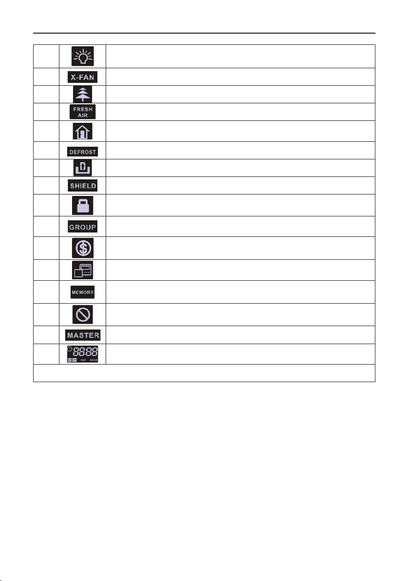
22 Light On/Off function
23 X-fan function
24 Health function
25 When Fresh Air is on, this unit is the fresh air unit
26 Out function
27 Outdoor unit defrosting status
28 Gate-control function
29 Shielding status
30 Child Lock status
31 One wired controller controls multiple indoor units
32 Save status of indoor unit
Wired Controller XK46
33
34
35 Invalid operation
36 Current wired controller connects master indoor unit
37 Timer zone:Display system clock and timer status
Note: When wired controller is connected with different indoor units, some functions will be different
It indicates the current wired controller is the slave wired controller (address of
wired controller is 02)
Memory status (The indoor unit resumes the original setting state after power
failure and then power recovery)
3
Wired Controller XK46
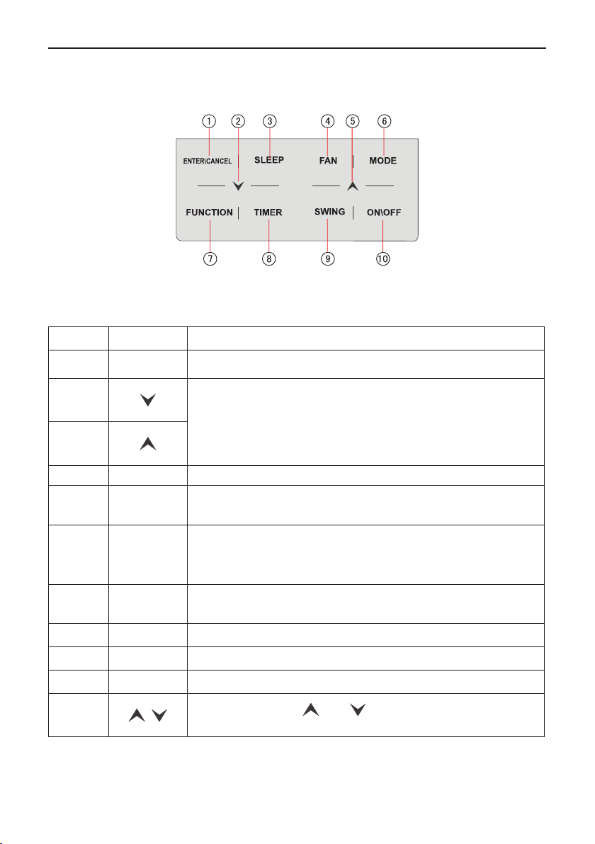
2. BUTTONS
2.1 Button Graphics
Fig. 2.1 Button graphics
2.1 Function Instruction of Buttons
Table 2.1 Function instruction of buttons
No. Buttons Instructions
1
2
5
ENTER/
CANCEL
Select and cancel function
(1) Set operating temperature of indoor unit
(2) Set Timer
(3) Switch Quiet mode, Air grade, Clean grade, set upper and lower
temperature limit under Save mode
(4) Set and inquiry parameter
3 SLEEP Set Sleep mode
4 FAN
6 MODE
7 FUNCTION
8 TIMER Timer setting
9 SWING Set up and down swing , left and right swing status
10 ON/OFF Indoor unit On/Off
2+5
+
Switch among auto, low speed, low-medium speed, medium speed,
medium-high speed, high speed and turbo status
Switch Auto,Cooling, Dry, Fan, Heating, Floor Heating, 3D Heating and
Space Heating modes for indoor unit. (Note: The Floor Heating, 3D
Heating and Space Heating function icon will show up when the unit has
those functions.)
Switch among Air, Quiet, Light, Health, Out, Save, Clean, E-heater and
X-fan functions.
Simultaneously press “ ” and “ ” for 5s to enter or cancel the Child
Lock function.
4
3. INSTALLATION AND COMMISSIONING
Wired Controller XK46
112
112
6
-R
3
2
.7
22
42.5
22
40
82.5
R3.3
5
Unit:mm
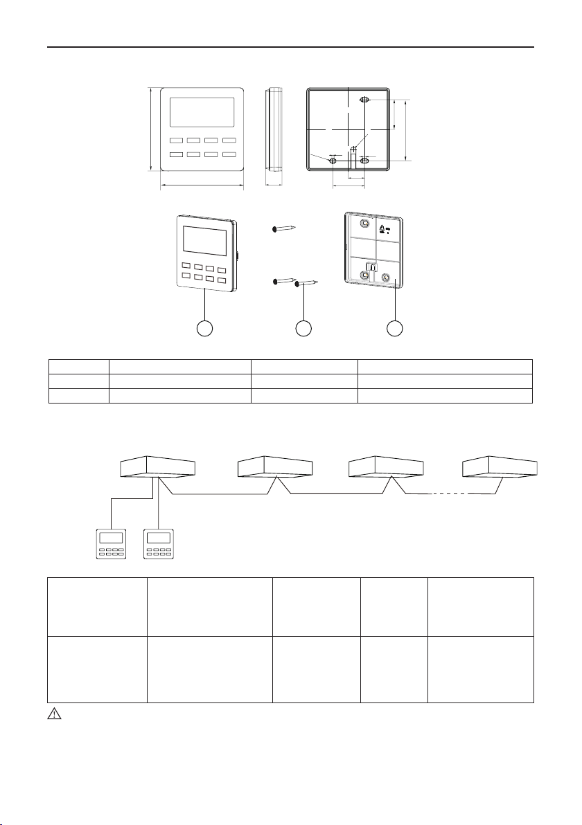
Fig. 3.1.1 Dimension of wired controller
31 2
Fig. 3.1.2 Parts of wired controller
No. 1 2 3
Name Panel of wired controller Screw M4*25 Soleplate of wired controller
Q'ty 1 3 1
3.1 Installation of Wired Controller
3.1.1 Communication Line Selection
Ind
In
do
oo
r un
it 1
L1
or u
nit 2
L2 L(n-1)
In
d
oo
r u
n
it 3
In
d
oo
r un
it n
1L02
L0
Slave wired
controller
Master wired
controller
L=L01+L02+L1+L2+......+L(n-1)(n≤16)
Fig. 3.2 Length of communication line
Total length of
Wire material type
communication line
between indoor unit and
Wire size (mm2)
Material
standard
wired controller L (m)
Light/Ordinary
polyvinyl chloride
sheathed cord.
(60227 IEC 52
L≤250 2×0.75~2×1.25
IEC 60227-
5:2007
Total length of
communication line
can't exceed 250m
/60227 IEC 53)
Note:
①
If the air conditioner is installed at the strong electromagnetic interference place,
communication line of the wired controller must use shielding twisted pair.
②
Materials of communication line for wired controller must be selected according to this
instruction manual strictly.
5
Remarks

Wired Controller XK46
3.1.2 Installation requirements
(1) Prohibit installing the wired controller at wet places.
(2) Prohibit installing the wired controller at direct sunshine places.
(3) Prohibit installing the wired controller at the place near high temperature objects or water-
splashing places.
(4) Prohibit installing the wired controller at the place where faces forward to the window.
Prevent abnormal work due to the interference from the other wired controller around.
3.1.3 Wiring Requirements
There are four network wiring methods between wired controller and indoor unit:
Outdoor unit
D1 D2
2
H
1
H
2
D
1
D
Fig. 3.3 One wired controller
controls one indoor unit
Indoor unit
Outdoor unit
D1 D2
Indoor unit
2
H
1
H
2
D
1
D
Fig. 3.4 Two wired controllers
control one indoor unit
6
 Loading...