

Page 1

Change for life
Wired Remote Controller XE71
(XE71-44/G)
Owner's Manual
Original Instructions
Thank you for choosing our product.
Please read this Owner’s Manual carefully before operation and retain it for future reference.
If you have lost the Owner's Manual visit www.greecomfort.com/resources/dealer-resources-
current-product/
Page 2

User Notice
◆ Never install the wired remote controller in highly humid environments or expose to direct
sunlight.
◆
Never drop, shake, toss or frequently disassemble the wired remote controller or the wireless
remote controller.
◆
Never operate the wired remote controller and the wireless remote controller with wet hands.
Do not remove or install the wired controller by yourself. If you have questions, please contact
◆
your local licensed HVAC technician.
This wired controller is compatible with several kinds of units.
◆
Some functions of the wired controller are not available for certain units,IRU more details please
refer to the owner’s manual of unit. Selecting an unavailable function will do nothing and will not
affect unit’s operation.
The wired controller is universal. The remote receiver is either in the indoor unit or in the wired
◆
controller. Please refer to the specific models.
When some indoor units are connected to the wired controller and the remote controller is set in
◆
the auto mode (where the temperature adjusts automatically), the remote controller will override
the wired controllers auto mode setting.
Please read the manual carefully before installing and using this product.
Page 3

Contents
Wired Remote Controller XE71 (XE71-44/G )...........................................................1
1 Symbols on LCD ...........................................................................................1
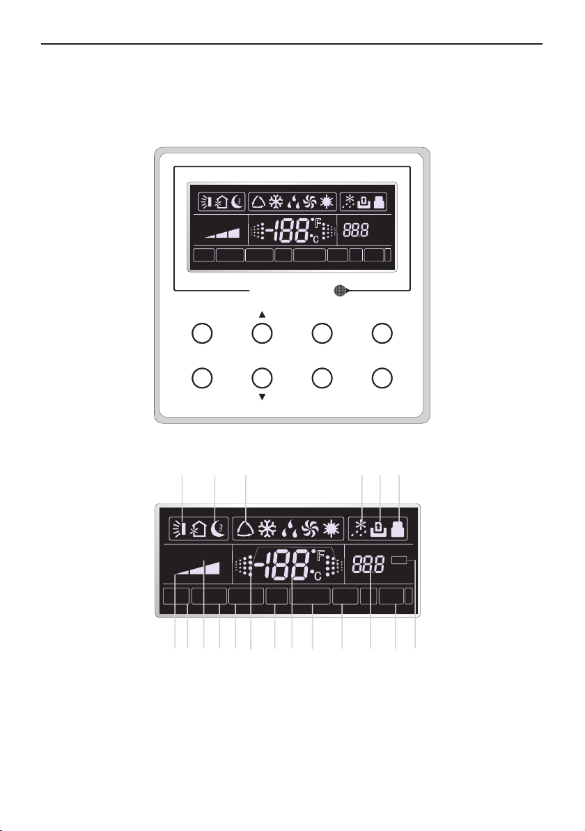
1.1 Outside View of the Wired Remote Controller ...................................................... 1
1.2 LCD Display of the Wired Remote Controlle
r ..................................................
...... 1
2 Touch Pad..................................................................................................... 2
2.1 Buttons on the Wired Remote Controller ..............................................................2
2.2 Function of the Buttons
......................................................................................... 3
3 Operation Instructions ...................................................................................4
3.1 On/Off ...................................................................................................................4
3.2 Mode Setting ......................................................................................................... 4
3.3 Temperature Setting ..............................................................................................4
3.4 Fan Setting
3.5 Timer Setting .........................................................................................................5
3.6 Swing Setting
3.7 Sleep Setting .........................................................................................................8
3.8 Turbo Setting .........................................................................................................9
3.9 E-heater Setting
3.10 Blow Setting
3.11 Other Functions ................................................................................................. 12
4 Installation and Dismantlement
4.1 Connection of the Signal Line of the Wired Remote Controller .......................... 13
............................................................................................................5
........................................................................................................ 7
.................................................................................................. 10
...................................................................................................... 11
.................................................................. 13
4.2 Installation of the Wired Remote Controller ........................................................ 13
4.3 Dismantlement of the Wired Remote Controller .................................................16
5 Errors Display ..............................................................................................16
Page 4
Wired Remote Controller XE71(XE71-44/G)
Wired Remote Controller XE71(XE71-44/G)
1 Symbols on LCD
1.1 Outside View of the Wired Remote Controller
AUTO TURBO
MEMORY
SHIELD
Enter/cancel
Enter/Cancel
Function
MASTER
SAVE
E-HEATER
Fig.1 Outside View of the Wired Remote Controller
1.2 LCD Display of the Wired Remote Controller
1 2
AUTOT URBO
SHIELD
MEMORY
3
MASTER
SAVE
E-HEATER
F
Fan
Timer
F
BLOW
BLOW
CO
QUIET
2
4
CO
SET
HOUR
Mode
On/Off
5
QUIET
2
A
U
T
O
6
SET
HOUR
A
U
T
O
8
10
9
7
1211
13 14
15 16
17 18 19
Fig.2 LCD Display of the Wired Remote Controller
1
Page 5
Wired Remote Controller XE71(XE71-44/G)
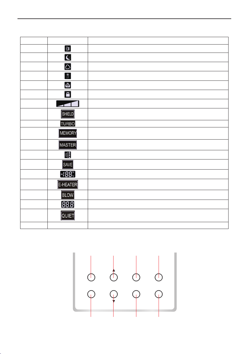
Table 1
No. Symbols Description
1
2
3
4
5
6
7
8
9
10
11
12
13
14
Swing function.
Sleep function (Only sleep 1).
Running modes of the indoor unit (Cooling, Dry, Fan and Heating).
Defrosting function for the outdoor unit.
Gate-control function.
Lock function.
High, middle, low or auto fan speed of the indoor unit.
Shield functions (buttons, temperature, On/Off or Mode is shielded
by the remote monitor.
Turbo function.
Memory function (The indoor unit resumes the original setting state
after power failure and then power recovery).
Master wired remote controller (this function is yet unavailable for
this unit).
It blinks under on state of the unit without operation of any button.
Energy-saving function (this function is yet unavailable for this unit).
Ambient/preset temperature value.
15
16
17
18
Electric auxiliary heating function. Not available in U.S.
Blow function.
Timing value.
Quiet function (two types: quiet and auto quiet)
(this function is yet unavailable for this unit).
19 SET It will be displayed under the debugging mode.
2 Touch Pad
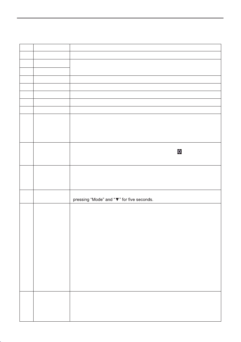
2.1 Buttons on the Wired Remote Controller
1 2 3
Enter/cancel
Enter/Cancel
Function
5
Fan
Timer
6
Fig. 3 Buttons on the Wired Remote Controller
Mode
On/Off
7
2
4
8
Page 6
Wired Remote Controller XE71(XE71-44/G)
2.2 Function of the Touch Pad Buttons
Table 2
No. Name Function
1 Enter/Cancel Function selection and cancellation.
2 ▲
6 ▼
3 Fan
4 Mode
5 Function
7 Timer Timer setting.
8 On/Off
4+2 ▲+Mode
Running temperature setting of the indoor unit, range:61~86°F(16~30℃).
①
Timer setting, range:0.5-24 hr.
②
Setting of the high/middle/low/auto fan speeds.
Setting the Cooling/Heating/Fan/Dry/Auto mode of the indoor unit.
Switchover to the Turbo/Save/E-heater/Blow etc. functions.
indoor unit on/off.
Turn
r 5 secs when unit is off to Enter/Cancel the Memory function (If
Press fo
memory is set, indoor unit will return to the last setting upon power
failure. If not, the indoor unit is defaulted to "off" af ter power recovery.
"Memory off" is the default setting at time of delivery).
3
+6
2
+6
4+6 Mode+▼
5+7 Function+Timer
5+7 Function+Timer
Fan+▼
▲+▼
By pressing these at the same time when unit is off will be displayed
on the wired remote controller.
Upon s
tartup of the unit, if there are no problems or if the unit is off,
press both at the same time for 5s to enter the lock mode where no
buttons will won’t respond when pressed. Repress both for 5s to cancel
this operation.
While "OFF" the Celsius and Fahrenheit sc
While "OFF", it's possible to go into the commissioning status by pressing
“Function” and “Timer for five seconds and leaving “00” in the temperature
display area. Then, pressing “Mode”, adjust the options in the timer area
by pressing “▲” and “▼”to select the following options:
Indoor ambient temperature is sensed by the return air temperature
①
sensor ( 01 displayed on the timer area).
Indoor ambient t emperature is sensed by the wired controller (02
②
displayed on the timer area).
The return air temperature sensor is selected under the cooling, dry, or
③
fan mode; while the wired controller temperature sensor is selected under
the heating or auto mode. (03 is displayed on the timer area).
The wired controller temperature sensor is selected under the cooling,
④
dry, or fan mode; while the return air temperature sensor is selected under
the heating mode. (04 is displayed on the timer display area).
While "OFF", it is possible to go to the c
pressing “Function” and “Timer” for five seconds. Press “Mode” button
until “01” icon is shown in the temperature display area. Press “▲” and “▼”
to select the following available options: ① Three low levels (01) ; ② Three
high levels (02).
ales can be switched by
ommissioning status by
3
Page 7
Wired Remote Controller XE71(XE71-44/G)
3 Operation Instructions
3.1 On/Off
Press On/Off to turn on the unit, press again to turn it off.
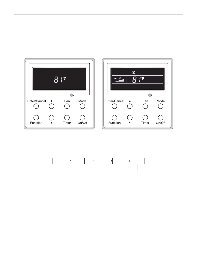
Note: The state shown in Fig.4 indicates unit is “Off” after powering on. The state shown in Fig.5
indicates the unit is “On” after powering on.
F
Fig. 4 “Off” State Fig. 5 “On” State
F
3.2 Mode Setting
While in the “On” state press "Mode"
sequence:Auto-Cooling-Dry-Fan-Heating.
Auto Cooling
to switch the operation modes in the following
Dry Fan
Heating
3.3 Temperature Setting
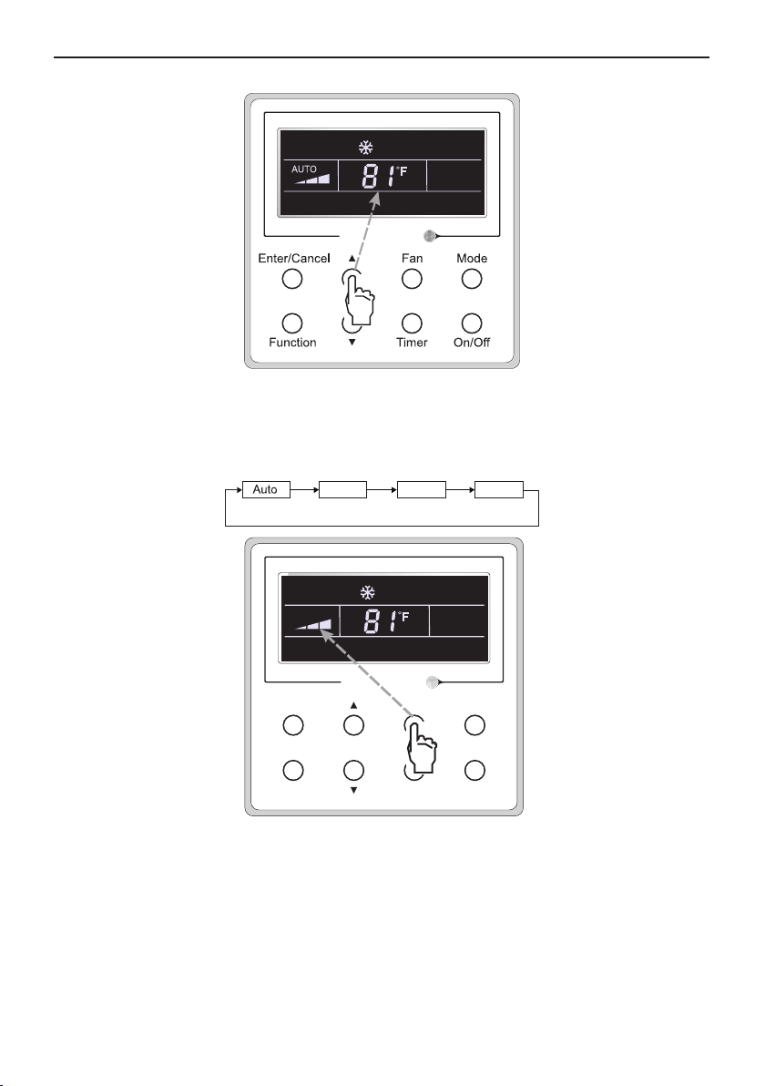
Press ▲or ▼ to increase/decrease the preset temperature. If either is pressed continuously,
the temperature will be increased or decreased by 1°F(1℃) every 0.5s,a s shown in Fig.6.
In the Cooling, Dry, Fan or Heating mode, the temperature setting range is 61°F~86°F(16℃
In the Auto mode, the setting temperature is not adjustable.
~30℃) .
4
Page 8
Wired Remote Controller XE71(XE71-44/G)
F
Fig.6
3.4 Fan Setting
In the “On”/”Off” state of the unit, press Fan and the fan speed of the indoor unit will
change in the order shown in Fig.7.
Low Middle
High
3.5 Timer Setting
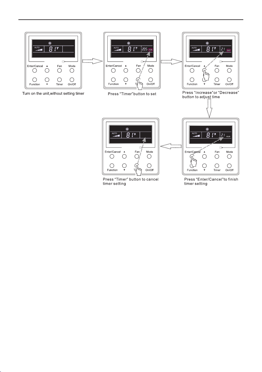
the “On”/”Off” state of the unit, press Timer to set timer off/on.
In
Timer "On" setting: Press "Timer", and the LCD will display “xx.x hour”, with “hour” blinking.
Then press ▲or ▼to adjust the time. Then prexx Enter/Cancel to confirm.
Timer "Off" setting: P
setting is canceled.
"Off" setting under the “On” state of the unit is shown as Fig.8.
Timer
AUTO
Enter/Cancel
Function
F
Fan Mode
Timer
On/Off
Fig.7
ress "Timer", if LCD won’t display xx.x hour then it means the timer
5
Page 9
Wired Remote Controller XE71(XE71-44/G)
F F F
F
F
Fig. 8 Timer off Setting under the “On” State of the Unit
Timer range: 0.5-24hr. Every press of ▲or ▼ will make the set time increased or decreased by
0.5hr. If either of them is pressed continuously, the set time will increase/ decrease by 0.5hr every
0.5s.
6
Page 10
Wired Remote Controller XE71(XE71-44/G)
3.6 Swing Setting
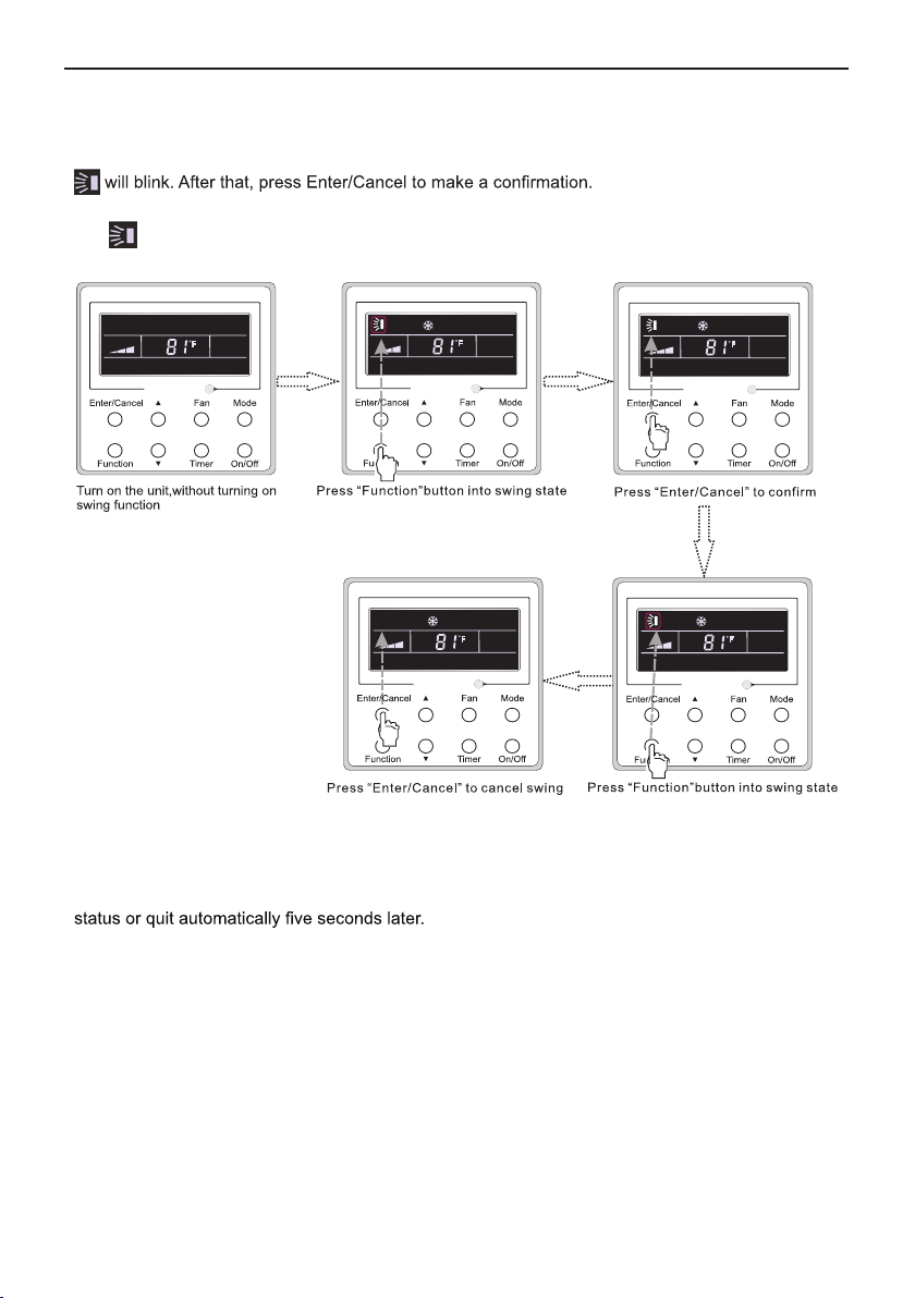
Swing On: Press Function under on state of the unit to activate the swing function. In this case,
Swing Off: When the Swing function is on, press Function to enter the Swing setting interface,
with blinking. After that, press Enter/Cancel to cancel this function.
Swing setting is shown as Fig.9.
F
F
F
F
F
Fig. 9 Swing Setting
Note:
① .
Sleep, Turbo or Blow setting is the same as the Swing setting.
② .
After the setting has been done, it has to press the key “Enter/Cancel” to back to the setting
7
Page 11
Wired Remote Controller XE71(XE71-44/G)
3.7 Sleep Setting
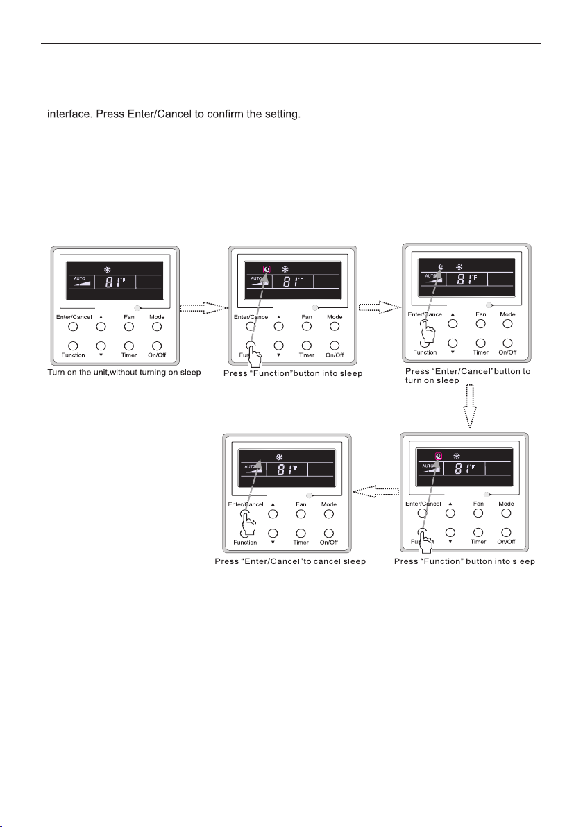
Sleep on: Press Function under on state of the unit till the unit enters the Sleep setting
Sleep off: When the Sleep function is activated, press Function to enter the Sleep setting
interface. After that, press Enter/Cancel to can this function.
In the Cooling or Dry mode, the temperature will increase by 1℃ after the unit runs under Sleep
1 for 1hr and 1℃ after another 1hr.After that, the unit will run at this temperature.
In the Heating mode, the temperature will decrease by 1℃ after the unit runs under Sleep 1 for
1hr and 1℃ after another 1hr. After that, the unit will run at this temperature.
Sleep setting is shown as Fig.10.
F
F
F
F
F
Fig. 10 Sleep Setting
8
Page 12
Wired Remote Controller XE71(XE71-44/G)
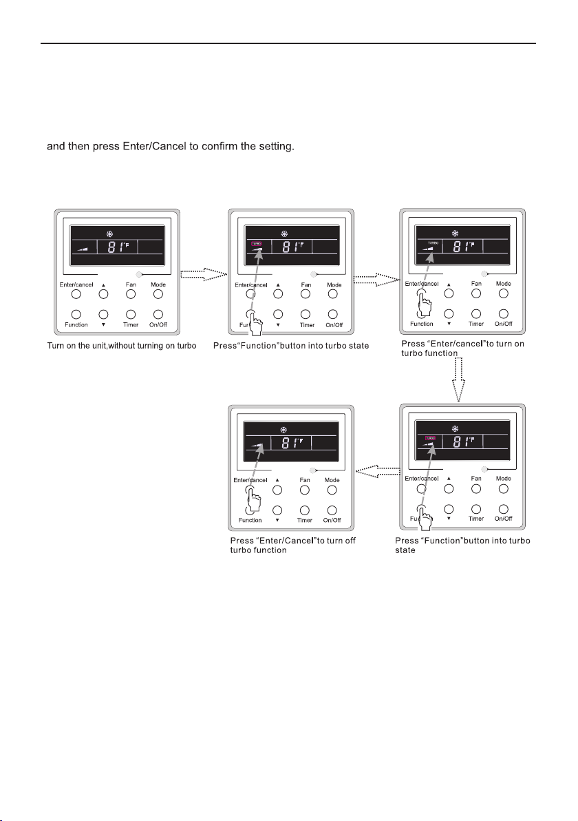
3.8 Turbo Setting
Turbo function: The unit at the high fan speed can realize quick cooling or heating so that the
room temperature can quickly approach the setting value.
In the Cooling or Heating mode, press Function till the unit enters the Turbo setting interface
When the Turbo function is activated, press Function to enter the Turbo setting interface and
then press Enter/Cancel to cancel this function.
Turbo function setting is as shown in Fig.11.
F
F
F
F
F
Fig.11 Turbo Setting
9
Page 13
Wired Remote Controller XE71(XE71-44/G)
3.9 E-heater Setting
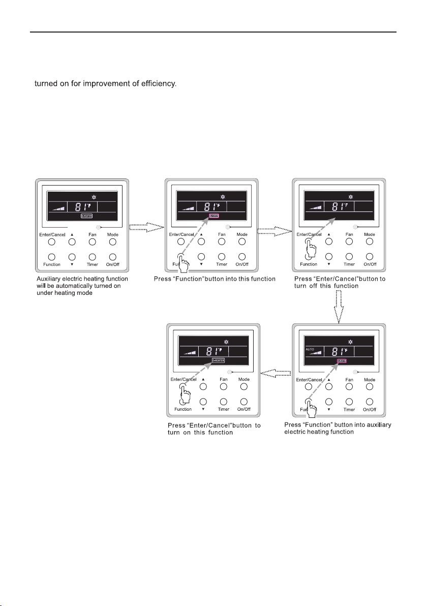
E-heater (auxiliary electric heating function): In the Heating mode, E-heater is allowed to be
Once the wired remote controller or the remote controller enters the Heating mode, this function
will be turned on automatically.
Press Function in the Heating mode to enter the E-heater setting interface and then press
Enter/Cancel to cancel this function.
Press Function to enter the E-heater setting interface, if the E-heater function is not activated,
and then press Enter/Cancel to turn it on.
The setting of this function is shown as Fig.12 below:
F
F
F
F
F
Fig.12 E-heater Setting
10
Page 14
Wired Remote Controller XE71(XE71-44/G)
3.10 Blow Setting
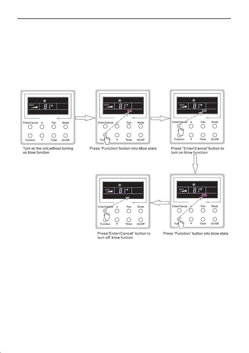
Blow function: After the unit is turned off, the water in evaporator of indoor unit will be
automatically evaporated to avoid mildew.
In the Cooling or Dry mode, press Function till the unit enters the Blow setting interface and
then press Enter/Cancel to active this function.
When the Blow function is activated, press Function to the Blow setting interface and then
press Enter/Cancel to cancel this function.
Blow function setting is as shown in Fig.13
F
F
F
F
F
Fig.13 Blow Setting
Notes:
① .
When the Blow function is activated, if turning off the unit by pressing On/Off or by the
remote controller, the indoor fan will run at the low fan speed for 2 min, with “BLOW” displayed on
the LCD. While, if the Blow function is deactivated, the indoor fan will be turned off directly.
② .
Blow function is unavailable in the Fan or Heating mode.
11
Page 15
Wired Remote Controller XE71(XE71-44/G)
3.11 Other Functions
(1). Lock
Upon startup of the unit without malfunction or under the “Off” state of the unit, press ▲ and
▼
at the same time for 5s till the wired remote controller enters the Lock function. In this case, LCD
displays
5s to switch memory states between memory on and memory off. When this function is activated,
Memory will be displayed. If this function is not set, the unit will be under the “Off” state after power
failure and then power recovery.
remote controller after power failure will resume its original running state upon power recovery.
Memory contents: On/Off, Mode, set temperature, set fan speed and Lock function.
commissioning status. Under this status, adjust the display in the temperature display area to “00”
through the button “Mode”, and then adjust the option of the temperature sensor in the timer display
area through the button ▲ or ▼.
.
After that, repress these two buttons at the same time for 5s to quit this function.
Under the Lock state, any other button press won’t get any response.
(2). Memory
Memory switchover: Under the “Off” state of the unit, press Mode and ▲ at the same time for
Memory recovery: If this function has been set for the wired remote controller, the wired
(3). Selection of the Temperature Sensor
Under OFF state of the unit, press both “Function” and “Timer” for five seconds to go the
① .
Indoor ambient temperature is sensed at the return air inlet(01 in the timer display area).
② .
Indoor ambient temperature is the sensed at the wired controller(02 in the timer display area).
③ .
Select the temperature sensor at the return air inlet under the cooling, dry and fan modes,
while select the temperature sensor at the wired controller under the heating and auto
modes.(03 in the timer display area).
④ .
Select the temperature sensor at the wired controller under the cooling, dry and fan modes,
and select the temperature sensor at the return air inlet under the heating mode and auto
modes (04 displayed in the timer display area).
Pressing the button “On/Off” also can quit this commissioning status but the set data won’t be
memorized.
Under the commissioning status, if there is no any operation in 20 seconds after the last button
press, it will back to the previous state without memorizing the current data.
Note:
After connected with indoor unit, if the type of ambient temperature sensor has not been manually
set, the wired controller will select the ambient temperature sensor according to the model of connected
IDU; if it connects to cassette type IDU, duct type IDU, floor ceiling type IDU, ceiling type IDU, it will
adopt ③, otherwise it will adopt ①. If the type of ambient temperature sensor is set manually, the wired
controller will subject to the manual setting, and will not set according to automatic IDU model selection.
12
Page 16
Wired Remote Controller XE71(XE71-44/G)
(4). Selection of the Fan Speed
go to the commissioning status, and then adjust the display in the temperature display area to 01
through the button “Mode” and adjust the setting of the fan speed, which comes to two options.
01: Three low fan speeds; 02: Three high fan speeds
Pressing the button “On/Off” also can quit this commissioning status but the set data won’t be memorized.
Under the commissioning status, if there is no any operation in 20 seconds after the last button
press, it will back to the previous state without memorizing the current data.
4 Installation and Dismantlement
4.1 Connection of the Signal Line of the Wired Remote Controller
● Open the cover of the electric control box of the indoor unit.
● Let the single line of the wired remote controller through the rubber ring.
● Connect the signal line of the wired remote controller to the 4-pin socket of the indoor unit .
● Tighten the signal wire with ties.
● The communication distance between the main board and the wired remote controller can
be up to 20 meters ( the standard distance is 8 meters)
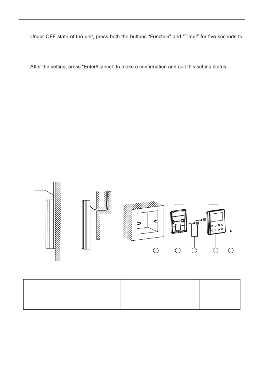
4.2 Installation of the Wired Remote Controller
PVC Pipe
1
3 4 52
Fig.14 Accessories for the Installation of the Wired Remote Controller
Table 3
No. 1 2 3 4 5
Front Panel of the
Wired Remote
Controller
Screw ST2.9X6
Name
Socket box
embedded
in the wall
Soleplate of the
Wired Remote
Controller
Sponge 20×20×2
Screw M4X25
13
Page 17
Wired Remote Controller XE71(XE71-44/G)
1
7
8 9
2
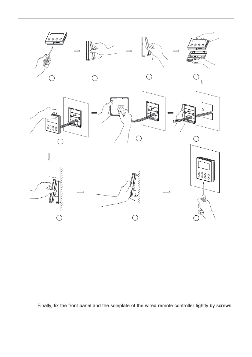
Note:CN1 is 485 communication inter face and it used
for connecting the 4-core commu nication wire.
These two needle stands(CN2 、CN3) are used for
connecting the smart zone controll er. There is no
sequence for these two needle stands. You can
connect one or two needle stand(s ) basing on the
requirement.
3 4
6
5
10
Fig.15
Fig.15 shows the installation steps of the wired remote controller, but there are some issues that need your attention.
(1). Prior to the installation, please firstly cut off the power supply of the wire buried in the
installation hole, that is, no operation is allowed with electricity during the whole installation.
(2). Pull out the four-core twisted pair line from the installation holes and then let it go through
the rectangular hole behind the soleplate of the wired remote controller.
(3). Stick the soleplate of wired controller on the wall and then use screw M4×25 to fix
soleplate and installation hole on wall together, attach the sponge 20×20×2 at the screw hole
and then press it with fingers to make sure it’s attached firmly.
(4). Insert the four-core twisted pair line into the slot of the wired remote controller and then
buckle the front panel and the soleplate of the wired remote controller together.
(5).
ST2.9X6.
14
Page 18
Wired Remote Controller XE71(XE71-44/G)
Smart zone
controller
Fig.16
Fig.16
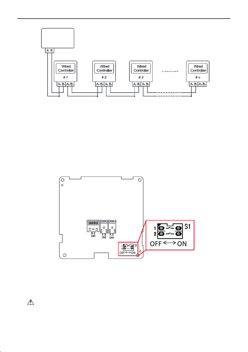
shows the schematic diagram of control system connection. XE
one controller (integrated control system). “n” indicates the number of communication node address
z
(programmable wired controller XE71). The complete system is composed of the smart zone controller,
wired controller XE71 and communication cable. The wired controller XE71can support 16 communication
node addresses at the most (n≤16).
Terminal A and terminal B of the smart zone controller are respectively connected to the corresponding
communication needle stand terminal of the #1wired controller by the communication cable; the other
needle stand of #1 wired controller is connected to the #2 wired controller through the telecommunication
cable and so forth until connect to the #n wired controller. Except the last wired controller in the control
system (only use CN2 or CN3, and the other one will not be connected), there’s no the sequence and the
importance for the wired controller. The series number in the figure is only for the sake of clarity.
71(XE71-44/G) can connect the smart
Fig.17
Fig.17
shows schematic diagram of DIP switch. There is a 2-bit DIP switch on the main board of wired
ontroller XE71(XE71-44/G). As for the last #n wired controller in the control system, the 1-bit and the 2-bit of the
c
DIP
switch should be manually pulled to position “on” and position “off” respectively. The DIP switches of
other wired controllers should be kept at the initial ex-factory status (1-bit and 2-bit are set at position
“off”).
CAUTION!
Please pay special attention to the following during the installation to avoid any problems with
the air conditioning unit due to electromagnetic interference.
① .
Separate the signal and communication lines of the wired remote controller from the power
15
Page 19
Wired Remote Controller XE71-44/G
cord and connection lines between the indoor and outdoor unit, with a minimum interval of 20cm,
otherwise the communication of the unit will probably work abnormally.
② .
If the air conditioning unit is installed where is vulnerable to electromagnetic interference,
then the signal and communication lines of the wired remote controller must be the shielding
twisted pair lines.
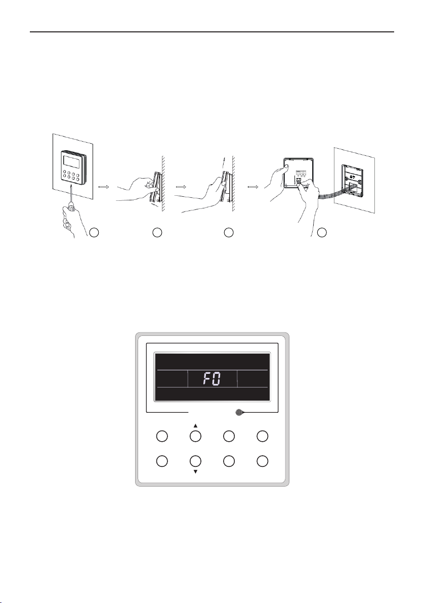
4.3 Dismantlement of the Wired Remote Controller
1 3 42
5 Errors Display
If there is an error occurring during the operation of the system, the error code will be displayed
on the LCD, as show in Fig.18. If multi errors occur at the same time, their codes will be displayed
circularly.
Note: In event of any error, please turn off the unit and contact the professionally skilled
personnel.
Enter/cancel
Enter/cancel
Function
Fig.18
16
Fan
Timer
Mode
On/Off
Page 20
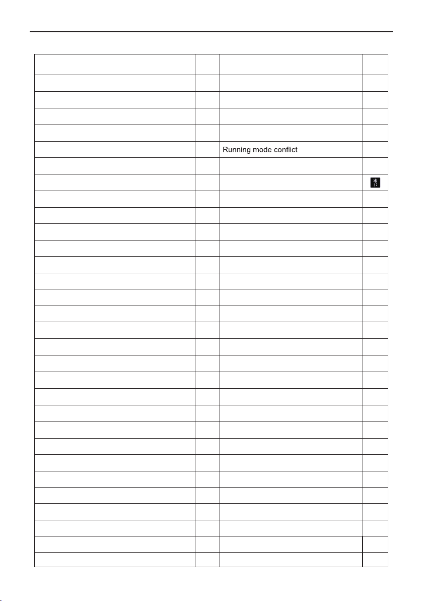
Wired Remote Controller XE71-44/G
Table 4 Meaning of Each Error
Error
Return air temperature sensor open/short
circuited
evaporator t emperature sensor open /short
circuited
Indoor unit liquid valve temperature sensor
open/short circuited
Indoor gas valve temperature sensor open/
short circuited
IPM temperature sensor open/short circuited P7
Outdoor ambient temperature sensor open/
short circuited
Outdoor unit condenser mid-tube temperature
sensor open/short circuited
Discharge temperature sensor open/short
circuited
Indoor and outdoor communication error E6 Compressor startup failure Lc
DC bus under-voltage protection PL High discharge temperature protection E4
DC bus over-voltage protection PH Overload protection E8
Compressor pha se current sensing circui t
error
Compressor demagnetization protection HE Over phase current protection P5
PFC protection Hc Compressor desynchronizing H7
IPM Temperature Protection P8 IPM Current protection H5
Over-power protection L9
Sy s t em charge short age or blo c ka g e
protection
Capacitor charging error PU
High pressure protection E1
Low pressure protection E3
Compressor stalling LE
Over-speeding LF
Drive board temperature sensor error PF Indoor unit full water error E9
AC contactor protection P9 Anti-freezing protection E2
Temperature drift protection PE AC input voltage abnormal PP
Sensor connection protection Pd Whole unit current sensing circuit error U5
DC bus voltage drop error U3 4-way valve reversing error U7
Outdoor fan 1 error protection L3 Motor stalling H6
Outdoor fan 2 error protection
compressor inhalation temperature sensor error
Error
Code
F1 Drive board communication error P6
F2 Compressor overheating protection H3
b5 Indoor and outdoor units unmatched LP
Communicat ion line mi sc onnecte d or
b7
expansion valve error
F3 Pump-down Fo
F4 Defrost or oil return
F5 Forced defrosting H1
U1 Whole unit over-current protection E5
Compre s s or pha s e l o ss/r e ve rs a l
protection
Frequency restricted/reduced with whole
F0
unit current protection
Frequency restricted/reduced with IPM
current protection
Frequency restricted/reduced with high
discharge temperature
Frequency restricted/reduced with antifreezing protection
Frequen cy rest r i cted/ r edu c e d with
overload protection
Frequency restricted/reduced with IPM
temperature protection
LA PG motor zero-crossing protection U8
dc
Error
Error
Code
dn
E7
Ld
F8
En
F9
FH
F6
EU
17
Page 21
GREE ELECTRIC APPLIANCES, INC. OF ZHUHAI
Add: West Jinji Rd, Qianshan, Zhuhai,Guangdong, China, 519070
Tel: (+86-756) 8522218
Fax: (+86-756) 8669426
E-mail: [email protected] www.gree.com
600005061061
 Loading...