

Gree GWH30LB-D3DNB2G, GWC36QF-D3DNB4G, GWH30QF-D3DNB4G, VIRU30HP230V1AH, GWC36LB-D3DNB2G Service Manual
...
’
Service Manual
Change for life
GREE ELECTRIC APPLIANCES, INC. OF ZHUHAI
Models:
GWC30LB-D3DNB2G
GWC30QF-D3DNB4G
GWH30LB-D3DNB2G
VIRU30HP230V1AH
GWH30QF-D3DNB4G
GWC36LB-D3DNB2G
GWC36QF-D3DNB4G
GWH36LB-D3DNB2G
GWH36LB-D3DNA5G
VIRU36HP230V1AH
GWH36QF-D3DNB4G
(Refrigerant R410A)

Table of Contents
Service Manual
Part
1. Summary
2. Specications
2.1 Specication Sheet ...........................................................................................................3
2.2 Capacity Variation Ratio According to Temperature .........................................................9
2.3 Noise Curve ....................................................................................................................10
2.4 Cooling and Heating Data Sheet in Rated Frequency ...................................................10
: Technical Information
Ⅰ
......................................................................................................................1
..........................................................................................................3
3. Outline Dimension Diagram
3.1 Indoor Unit ...................................................................................................................... 11
3.2 Outdoor Unit ................................................................................................................... 11
4. Refrigerant System Diagram
5. Electrical Part
5.1 Wiring Diagram ...............................................................................................................16
5.2 PCB Printed Diagram .....................................................................................................19
6. Function and Control
.........................................................................................................16
......................................................................................22
.......................................................................1
...................................................................... 11
....................................................................13
6.1 Remote Controller Introduction of YAN1F6F ..................................................................22
6.2 Remote Controller Introduction of YV1FB9F ..................................................................27
6.3 GREE+ App Operation Manual ......................................................................................31
6.4 Ewpe Smart App Operation Manual ...............................................................................32
6.5 Brief Description of Modes and Functions ......................................................................33
Part
: Installation and Maintenance
Ⅱ
7. Notes for Installation and Maintenance
8. Installation
8.1 Installation Dimension Diagram ......................................................................................39
8.2 Installation Parts-checking ............................................................................................41
8.3 Selection of Installation Location ....................................................................................41
8.4 Requirements for electric connection .............................................................................41
8.5 Installation of Indoor Unit ................................................................................................41
8.6 Installation of Outdoor Unit .............................................................................................44
................................................................................................................39
.................................................36
..........................................36
8.7 Vacuum Pumping and Leak Detection ...........................................................................45
8.8 Check after Installation and Test Operation ...................................................................45
Table of contents

Service Manual
9. Troubleshooting
9.1 Flashing LED of Indoor/Outdoor Unit and Primary Judgement ......................................46
9.2 How to Check Simply the Main Part ...............................................................................55
9.3 Troubleshooting for Normal Malfunction .........................................................................71
10. Exploded View and Parts List
10.1 Indoor Unit ....................................................................................................................73
10.2 Outdoor Unit .................................................................................................................81
11. Removal Procedure
11.1 Removal Procedure of Indoor Unit ...............................................................................87
11.2 Removal Procedure of Outdoor Unit ............................................................................96
Appendix:
Appendix 1: Reference Sheet of Celsius and Fahrenheit ..................................................107
Appendix 2: Conguration of Connection Pipe ...................................................................107
Appendix 3: Pipe Expanding Method .................................................................................108
......................................................................................................................107
..................................................................................................46
..............................................................73
.......................................................................................87
Appendix 4: List of Resistance for Temperature Sensor ....................................................109
Service Manual
Part
: Technical Information
Ⅰ
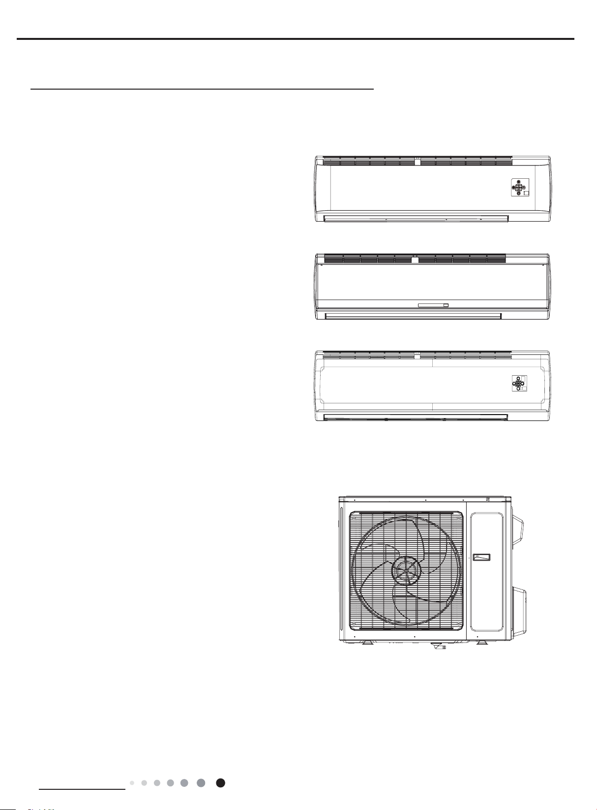
1. Summary
Indoor Unit:
GWC30LB-D3DNB2G/I GWH30LBD3DNB2G/I GWC36LB-D3DNB2G/I
GWH36LB-D3DNB2G/I
VIRU30HP230V1AH
VIRU36HP230V1AH
GWH36LB-D3DNA5G/I
GWC30QF-D3DNB4G/I
GWH30QF-D3DNB4G/I
GWC36QF-D3DNB4G/I
GWH36QF-D3DNB4G/I
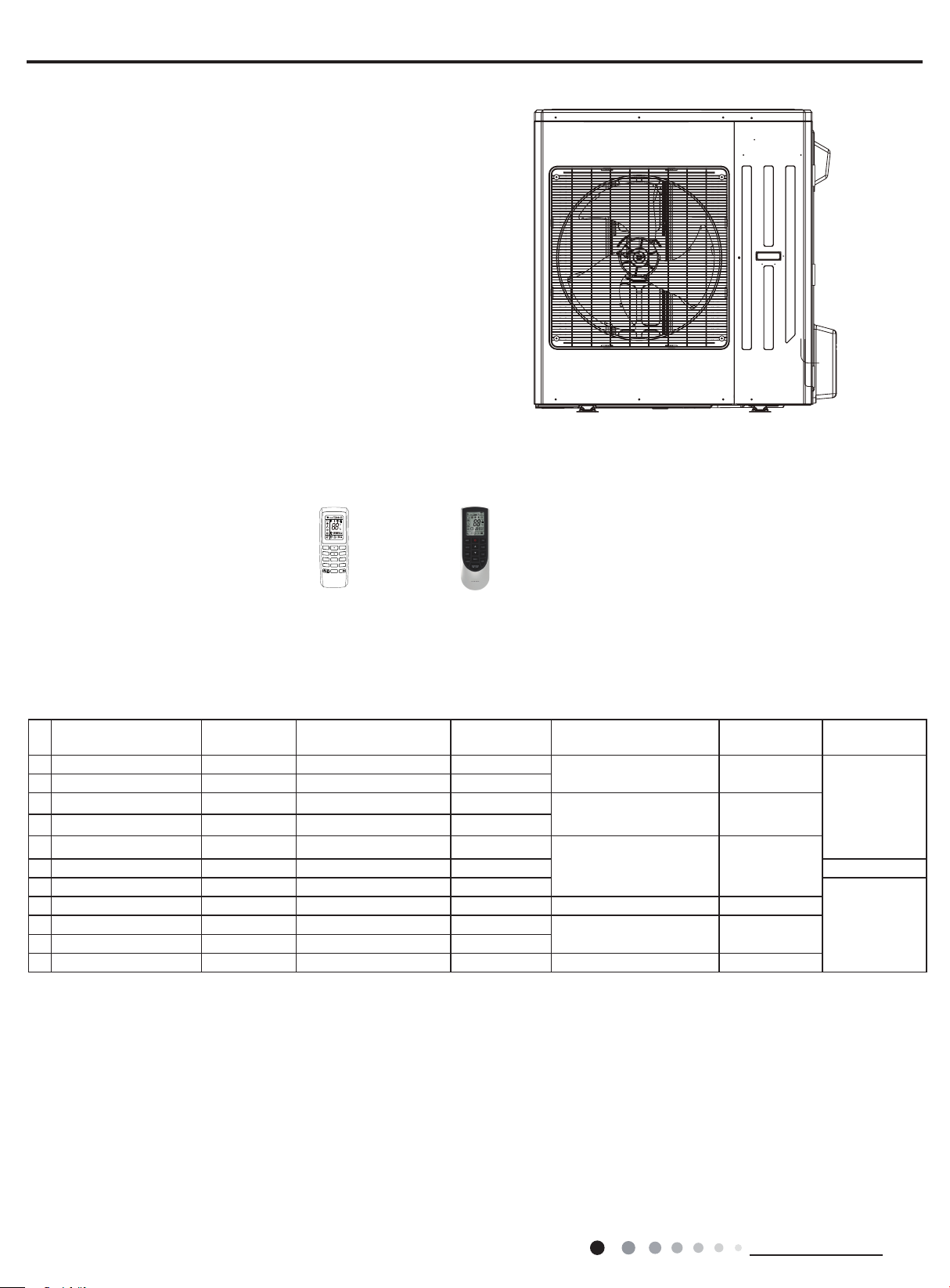
Outdoor Unit:
GWC30LB-D3DNA3G/O
VIRU30HP230V1AO
GWC36LB-D3DNA3G/O
VIRU36HP230V1AO
Technical Information
1
MODE
FAN
TIMER ON
TURBO
CLOCK
TEMP
IFEEL
ON/OFF
SWING
TIMER OFF
SLEEP
X-FAN
WIFI
VIRU36HP230V1AO
VIRU30HP230V1AO
Remote Controller:
Service Manual
A
YAN1F6FYV1FB9F
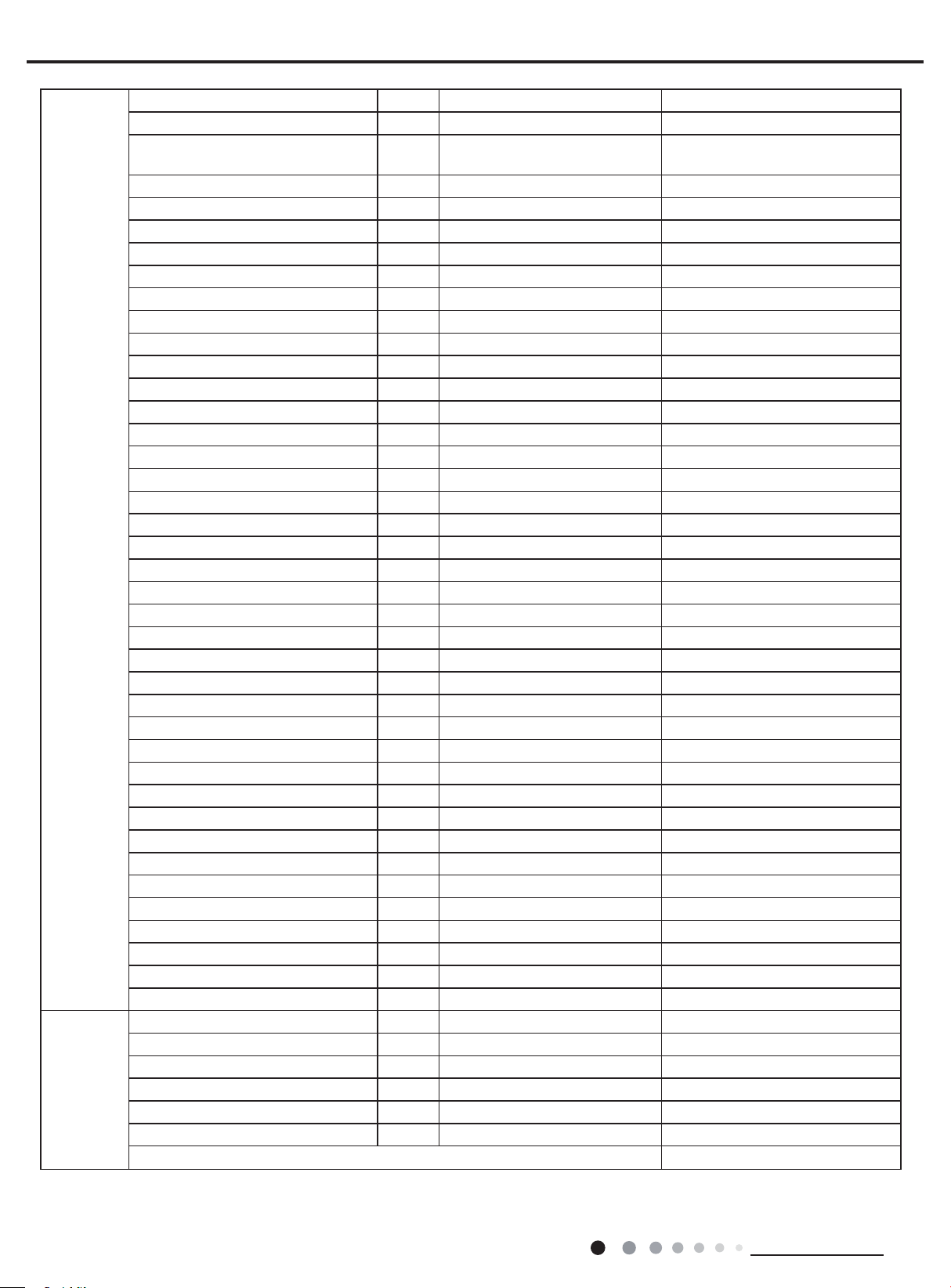
Model List:
No Model Product code Indoor model
1
GWC30LB-D3DNB2G CB433000102 GWC30LB-D3DNB2G/I CB433N00102
2
GWC30QF-D3DNB4G CB434005001 GWC30QF-D3DNB4G/I CB434N05001
3 GWC36LB-D3DNB2G CB433000302 GWC36LB-D3DNB2G/I CB433N00302
4 GWC36QF-D3DNB4G CB434005102 GWC36QF-D3DNB4G/I CB434N05102
5
GWH36LB-D3DNB2G CB433000402 GWH36LB-D3DNB2G/I CB433N00402
6 GWH36LB-D3DNA5G CB169001002 GWH36LB-D3DNA5G/I CB169N01002 YV1FB9F(WiFi)
7
GWH36QF-D3DNB4G CB434004901 GWH36QF-D3DNB4G/I CB434N04901
8
VIRU36HP230V1AH CB432010100 VIRU36HP230V1AH CB432N10100 VIRU36HP230V1AO CB432W10100
9
GWH30LB-D3DNB2G CB433000202 GWH30LB-D3DNB2G/I CB433N00202
10
GWH30QF-D3DNB4G CB434004801 GWH30QF-D3DNB4G/I CB434N04801
11
VIRU30HP230V1AH CB432010000 VIRU30HP230V1AH CB432N10000 VIRU30HP230V1AO CB432W10000
Indoor product
code
Outdoor model
GWC30LB-D3DNA3G/O CB171W10700
GWC36LB-D3DNA3G/O CB171W10900
VIRU36HP230V1AO CB171W10800
VIRU30HP230V1AO CB171W10600
Outdoor
product code
Remote
Controller
YAN1F6F(WiFi)
YAN1F6F(WiFi)
2
Technical Information

Service Manual
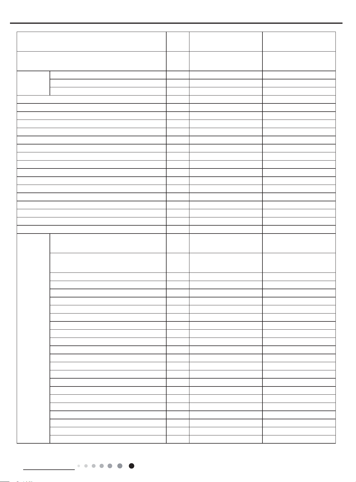
2. Specications
2.1 Specication Sheet
Model
Product Code
Rated Voltage V~ 208/230 208/230
Power Supply
Power Supply Mode Outdoor Outdoor
Cooling Capacity(Min~Max) Btu/h 28000(9485~30026) 28000(9485~30026)
Heating Capacity(Min~Max) Btu/h / 28400(9997~32994)
Cooling Power Input(Min~Max) W 2700(350~3900) 2705(600~3900)
Heating Power Input(Min~Max) W / 2800(650~4000)
Cooling Power Current A 11.5 11.5
Heating Power Current A / 12
Rated Input W 3900 4000
Rated Current A 17 17
Rated Heating Current A / 17.5
Air Flow Volume(SH/H/M/L) CFM 706/618/530/412 706/618/530/412
Dehumidifying Volume Pint/h 6.34 6.34
EER (Btu/h)/W 10.37 10.36
COP (Btu/h)/W / 10.14
SEER 18 18
SCOP / 9
Application Area yd
Indoor Unit
Rated Frequency Hz 60 60
Phases 1 1
2
Model of indoor unit
Indoor Unit Product Code
Fan Type Cross-ow Cross-ow
Diameter Length(DXL) inch Φ4 1/4X20 9/16X2 Φ4 1/4X20 9/16X2
Fan Motor Cooling Speed (SH/H/M/L) r/min 1350/1150/950/850 1350/1150/950/850
Fan Motor Heating Speed (SH/H/M/L) r/min / 1350/1200/1000/800
Output of Fan Motor W 70 70
Fan Motor RLA A 0.4 0.4
Fan Motor Capacitor μF / /
Evaporator Form Aluminum Fin-copper Tube Aluminum Fin-copper Tube
Pipe Diameter inch Φ9/32 Φ9/32
Row-n Gap inch 2-1/16 2-1/16
Coil Length (LXDXW) inch 42 9/32X1X15 42 9/32X1X15
Swing Motor Model MP24BA MP24BA
Output of Swing Motor W 1.5 1.5
Fuse A 3.15 3.15
Sound Pressure Level (SH/H/M/L) dB (A) 51/45/41/37 51/45/41/37
Sound Power Level (SH/H/M/L) dB (A) 61/55/51/47 61/55/51/47
Dimension (WXHXD) inch 53 9/64X12 53/64X9 61/64 53 9/64X12 53/64X9 61/64
Dimension of Carton Box (LXWXH) inch 56 39/64X16 29/64X13 55/64 56 39/64X16 29/64X13 55/64
Dimension of Package (LXWXH) inch 56 47/64X16 37/64X14 7/16 56 47/64X16 37/64X14 7/16
Net Weight Ib 41.9 41.9
Gross Weight Ib 51.8 51.8
GWC30LB-D3DNB2G
GWC30QF-D3DNB4G
CB433000102
CB434005001
41.86-62.19 41.86-62.19
GWC30LB-D3DNB2G/I
GWC30QF-D3DNB4G/I
CB433N00102
CB434N05001
GWH30LB-D3DNB2G
GWH30QF-D3DNB4G
CB433000202
CB434004801
GWH30LB-D3DNB2G/I
GWH30QF-D3DNB4G/I
CB433N00202
CB434N04801
Technical Information
3
Service Manual
Outdoor Unit
Connection
Pipe
Model of Outdoor Unit GWC30LB-D3DNA3G/O
Outdoor Unit Product Code CB171W10700 CB171W10600
Compressor Manufacturer/Trademark
Compressor Model QXAS-D23zX090 QXAS-D23zX090
Compressor Oil RB68EP RB68EP
Compressor Type Rotary Rotary
Compressor Locked Rotor Amp (L.R.A) 40 40
Compressor RLA A 13.45 13.45
Compressor Power Input W 2450 2450
Overload Protector 1NT11L-6233 1NT11L-6233
Throttling Method Electron expansion valve+Capillary Electron expansion valve+Capillary
Operation temp ºF 61~86 61~86
Ambient temp (cooling) ºF 0~115 0~115
Ambient temp (heating) ºF / -4~75
Condenser Form Aluminum Fin-copper Tube Aluminum Fin-copper Tube
Pipe Diameter inch Φ5/16 Φ5/16
Rows-n Gap inch 2-1/16 2-1/16
Coil Length (LXDXW) inch 37 1/2X1 1/2X29 7/16 37 1/2X1 1/2X29 7/16
Fan Motor Speed rpm 795 795
Output of Fan Motor W 120 120
Fan Motor RLA A 0.45 0.45
Fan Motor Capacitor μF / /
Air Flow Volume of Outdoor Unit CFM 2354 2354
Fan Type Axial-ow Axial-ow
Fan Diameter inch Φ21 21/32 Φ21 21/32
Defrosting Method / Automatic Defrosting
Climate Type T1 T1
Isolation I I
Moisture Protection IPX4 IPX4
Design Pressure(High) PSIG 550 550
Design Pressure(Low) PSIG 240 240
Sound Pressure Level (H/M/L) dB (A) 62/-/- 62/-/-
Sound Power Level (H/M/L) dB (A) 72/-/- 72/-/-
Dimension (WXHXD) inch 39 1/2X31 7/64X16 13/16 39 1/2X31 7/64X16 13/16
Dimension of Carton Box (LXWXH) inch 42 1/2X19X33 42 1/2X19X33
Dimension of Package (LXWXH) inch 42 21/32X19 13/64X33 21/32 42 21/32X19 13/64X33 21/32
Net Weight Ib
Gross Weight Ib 163.1 165.4
Refrigerant R410A R410A
Refrigerant Charge oz 84.66 84.66
Length ft 24.6 24.6
Gas Additional Charge oz/ft 0.2 0.5
Outer Diameter Liquid Pipe inch Φ1/4 Φ1/4
Outer Diameter Gas Pipe inch Φ5/8 Φ5/8
Max Distance Height ft 32 3/16 32 3/16
Max Distance Length ft 98 27/64 98 27/64
Note:The connection pipe applies metric diameter.
ZHUHAI LANDA COMPERSSOR
CO.LTD.
152.1 154.3
VIRU30HP230V1AO
ZHUHAI LANDA COMPERSSOR
CO.LTD.
The above data is subject to change without notice; please refer to the nameplate of the unit.
4
Technical Information
Service Manual
GWH36LB-D3DNB2G
GWH36LB-D3DNA5G
GWH36QF-D3DNB4G
CB433000402
CB169001002
CB434004901
Model
Product Code
GWC36LB-D3DNB2G
GWC36QF-D3DNB4G
CB433000302
CB434005102
Rated Voltage V~ 208/230 208/230
Power Supply
Rated Frequency Hz 60 60
Phases 1 1
Power Supply Mode Outdoor Outdoor
Cooling Capacity(Min~Max) Btu/h 33600(7404~35997) 33600(7404~35997)
Heating Capacity(Min~Max) Btu/h / 34600(14979~35997)
Cooling Power Input(Min~Max) W 4100 4100(450~4300)
Heating Power Input(Min~Max) W / 3800(560~4300)
Cooling Power Current A 17 17
Heating Power Current A / 16.5
Rated Input W 4300 4300
Rated Current A 20 20
Rated Heating Current A / 20
Air Flow Volume(SH/H/M/L) CFM 736/647/530/412 736/647/530/412
Dehumidifying Volume Pint/h 7.4 7.4
EER (Btu/h)/W 8.20 8.20
COP (Btu/h)/W / 9.11
SEER 18.00 18.00
SCOP / 9.00
Application Area yd
Model of indoor unit
Indoor Unit Product Code
2
55.01-83.72 55.01-83.72
GWC36LB-D3DNB2G/I
GWC36QF-D3DNB4G/I
GWH36LB-D3DNB2G/I
GWH36LB-D3DNA5G/I
GWH36QF-D3DNB4G/I
CB433N00302
CB434N05102
CB433N00402
CB169N01002
CB434N04901
Fan Type Cross-ow Cross-ow
Diameter Length(DXL) inch Φ4 1/4X20 9/16 Φ4 1/4X20 9/16
Fan Motor Cooling Speed (SH/H/M/L) r/min 1400/1250/1000/800 1400/1250/1000/800
Fan Motor Heating Speed (SH/H/M/L) r/min / 1400/1250/1050/850
Output of Fan Motor W 70 70
Fan Motor RLA A 0.4 0.4
Fan Motor Capacitor μF / /
Evaporator Form Aluminum Fin-copper Tube Aluminum Fin-copper Tube
Indoor Unit
Pipe Diameter inch Φ9/32 Φ9/32
Row-n Gap inch 2-1/16 2-1/16
Coil Length (LXDXW) inch 42 9/32X1X15X2 42 9/32X1X15X2
Swing Motor Model MP24BA MP24BA
Output of Swing Motor W 1.5 1.5
Fuse A 5 5
Sound Pressure Level (SH/H/M/L) dB (A) 54/49/44/37 54/49/44/37
Sound Power Level (SH/H/M/L) dB (A) 64/59/54/47 64/59/54/47
Dimension (WXHXD) inch 53 9/64X12 53/64X9 61/64 53 9/64X12 53/64X9 61/64
Dimension of Carton Box (LXWXH) inch 56 39/64X16 29/64X13 55/64 56 39/64X16 29/64X13 55/64
Dimension of Package (LXWXH) inch 56 47/64X16 37/64X14 7/16 56 47/64X16 37/64X14 7/16
Net Weight Ib 41.9 41.9
Gross Weight Ib 51.8 51.8
Technical Information
5
Service Manual
Outdoor Unit
Connection
Pipe
Model of Outdoor Unit GWC36LB-D3DNA3G/O(LC)
Outdoor Unit Product Code CB171W10900 CB171W10800
MITSUBISHI ELECTRIC
Compressor Manufacturer/Trademark
Compressor Model TNB306FPGMC TNB306FPGMC
Compressor Oil FV50S FV50S
Compressor Type Rotary Rotary
Compressor Locked Rotor Amp (L.R.A) 67.00 67.00
Compressor RLA A 17.5 17.5
Compressor Power Input W 3010 3010
Overload Protector CS01F272H01 CS01F272H01
Throttling Method Electron expansion valve Electron expansion valve
Operation temp ºF 61~86 61~86
Ambient temp (cooling) ºF 0~109 0~109
Ambient temp (heating) ºF / -4~75
Condenser Form Aluminum Fin-copper Tube Aluminum Fin-copper Tube
Pipe Diameter inch Φ5/16 Φ5/16
Rows-n Gap inch 2-1/16 2-1/16
Coil Length (LXDXW) inch 37X1 3/4X30 37X1 3/4X30
Fan Motor Speed rpm 890 890
Output of Fan Motor W 170 170
Fan Motor RLA A 0.73 0.73
Fan Motor Capacitor μF / /
Air Flow Volume of Outdoor Unit CFM 2589 2589
Fan Type Axial-ow Axial-ow
Fan Diameter inch Φ21 21/32 Φ21 21/32
Defrosting Method / Automatic Defrosting
Climate Type T1 T1
Isolation I I
Moisture Protection IPX4 IPX4
Design Pressure(High) PSIG 550 550
Design Pressure(Low) PSIG 240 240
Sound Pressure Level (H/M/L) dB (A) 65/-/- 65/-/-
Sound Power Level (H/M/L) dB (A) 75/-/- 75/-/-
Dimension (WXHXD) inch 39 1/2X31 7/64X16 13/16 39 1/2X31 7/64X16 13/16
Dimension of Carton Box (LXWXH) inch 42 1/2X19X33 42 1/2X19X33
Dimension of Package (LXWXH) inch 42 21/32X19 13/64X33 21/32 42 21/32X19 13/64X33 21/32
Net Weight Ib 154.3 161.0
Gross Weight Ib 165.4 172.0
Refrigerant R410A R410A
Refrigerant Charge oz 84.66 91.71
Length ft 24.6 24.6
Gas Additional Charge oz/ft 0.5 0.5
Outer Diameter Liquid Pipe inch Φ1/4 Φ1/4
Outer Diameter Gas Pipe inch Φ5/8 Φ5/8
Max Distance Height ft 32 3/16 32 3/16
Max Distance Length ft 98 27/64 98 27/64
Note:The connection pipe applies metric diameter.
(GUANGZHOU)COMPRESSOR
CO. LTD
VIRU36HP230V1AO(LCLH)
MITSUBISHI ELECTRIC
(GUANGZHOU)COMPRESSOR
CO. LTD
The above data is subject to change without notice; please refer to the nameplate of the unit.
6
Technical Information
Service Manual
Model VIRU36HP230V1AH VIRU30HP230V1AH
Product Code CB432010100 CB432010000
Rated Voltage V~ 208/230 208/230
Power Supply
Rated Frequency Hz 60 60
Phases 1 1
Power Supply Mode Outdoor Outdoor
Cooling Capacity(Min~Max) Btu/h 33000(30700~40900) 28000(5500~30700)
Heating Capacity(Min~Max) Btu/h 34600(16700~49400) 28700(4300~35200)
Cooling Power Input(Min~Max) W 3220(500~4100) 2500(420~3650)
Heating Power Input(Min~Max) W 3100(1000~7000) 2700(520~5800)
Cooling Power Current A 14.7 11.4
Heating Power Current A 14.2 12.4
Rated Input W 7000 5800
Rated Current A 19 17
Rated Heating Current A 30 25
Air Flow Volume(SH/H/M/L) CFM 824/706/589/441 824/706/589/441
Dehumidifying Volume Pint/h 7.4 6.34
EER (Btu/h)/W 10.25 11.2
COP (Btu/h)/W 11.16 10.63
SEER 23 23
SCOP / /
Application Area yd
Model of indoor unit VIRU36HP230V1AH
2
55.01-83.72 41.86-62.19
VIRU30HP230V1AH
Indoor Unit Product Code CB432N10100 CB432N10000
Fan Type Cross-ow Cross-ow
Diameter Length(DXL) inch Φ4 1/4X20 9/16 Φ4 1/4X20 9/16
Fan Motor Cooling Speed (SH/H/M/L) r/min 1550/1300/1150/850 1550/1300/1150/850
Fan Motor Heating Speed (SH/H/M/L) r/min 1500/1300/1150/1000 1500/1300/1150/1000
Output of Fan Motor W 70 70
Fan Motor RLA A 0.4 0.4
Fan Motor Capacitor μF / /
Evaporator Form Aluminum Fin-copper Tube Aluminum Fin-copper Tube
Pipe Diameter inch Φ9/32 Φ9/32
Indoor Unit
Row-n Gap inch 2-1/16 2-1/16
Coil Length (LXDXW) inch 42 9/32X1X15 42 9/32X1X15
Swing Motor Model MP24BA MP24BA
Output of Swing Motor W 2 2
Fuse A 5 5
Sound Pressure Level (SH/H/M/L) dB (A) 54/49/44/37 54/49/44/37
Sound Power Level (SH/H/M/L) dB (A) 64/59/54/47 64/59/54/47
Dimension (WXHXD) inch 53 9/64X12 53/64X9 61/64 53 9/64X12 53/64X9 61/64
Dimension of Carton Box (LXWXH) inch 56 39/64X16 29/64X13 55/64 56 39/64X16 29/64X13 55/64
Dimension of Package (LXWXH) inch 56 47/64X16 37/64X14 7/16 56 47/64X16 37/64X14 7/16
Net Weight Ib 41.9 41.9
Gross Weight Ib 51.8 51.8
Technical Information
7
Service Manual
Outdoor Unit
Connection
Pipe
Model of Outdoor Unit VIRU36HP230V1AO
Outdoor Unit Product Code CB432W10100 CB432W10000
Compressor Manufacturer/Trademark
Compressor Model QXAW-F518zX440C QXFW-D318ZX035
Compressor Oil FV50S or equivalent FW68DA or equivalent
Compressor Type Rotary Rotary
Compressor Locked Rotor Amp (L.R.A) 36 30
Compressor RLA A 24±10% 23
Compressor Power Input W 5830±3% 3350±3%
Overload Protector / /
Throttling Method Electron expansion valve Electron expansion valve
Operation temp ºF 61~86 61~86
Ambient temp (cooling) ºF 0~109 0~109
Ambient temp (heating) ºF -31~75 -31~75
Condenser Form Aluminum Fin-copper Tube Aluminum Fin-copper Tube
Pipe Diameter inch Φ5/16 Φ5/16
Rows-n Gap inch 2-1/16 2-1/16
Coil Length (LXDXW) inch 41 37/64X1 1/2×38 13/64 41 37/64X1 1/2×38 13/64
Fan Motor Speed rpm 940 850
Output of Fan Motor W 170 170
Fan Motor RLA A 0.73 0.73
Fan Motor Capacitor μF / 0
Air Flow Volume of Outdoor Unit CFM 3119 5300
Fan Type Axial-ow Axial-ow
Fan Diameter inch Φ21 21/32 Φ21 21/32
Defrosting Method Automatic Defrosting Automatic Defrosting
Climate Type T1 T1
Isolation I I
Moisture Protection IPX4 IPX4
Design Pressure(High) PSIG 550 550
Design Pressure(Low) PSIG 240 240
Sound Pressure Level (H/M/L) dB (A) 63/-/- 61/-/-
Sound Power Level (H/M/L) dB (A) 73/-/- 73/-/-
Dimension (WXHXD) inch 43 37/64X43 1/2X16 9/64 43 37/64X43 1/2X16 9/64
Dimension of Carton Box (LXWXH) inch 45 1/2X18 57/64X45 39/64 45 1/2X18 57/64X45 39/64
Dimension of Package (LXWXH) inch 45 39/64X19 X44 9/32 45 39/64X19 X44 9/32
Net Weight Ib
Gross Weight Ib 271.17 240.3
Refrigerant R410A R410A
Refrigerant Charge oz 123.5 123.5
Length ft 24.6 24.6
Gas Additional Charge oz/ft 0.3 0.3
Outer Diameter Liquid Pipe inch Φ1/4 Φ1/4
Outer Diameter Gas Pipe inch Φ5/8 Φ5/8
Max Distance Height ft 98.4 98.4
Max Distance Length ft 164 164
Note:The connection pipe applies metric diameter.
ZHUHAI LANDA COMPRESSOR
CO., LTD
253.53 229.3
VIRU30HP230V1AO
ZHUHAI LANDA COMPRESSOR
CO., LTD
The above data is subject to change without notice; please refer to the nameplate of the unit.
8
Technical Information
Service Manual
Cooling Heating
)O
Capacity ratio (%)
75
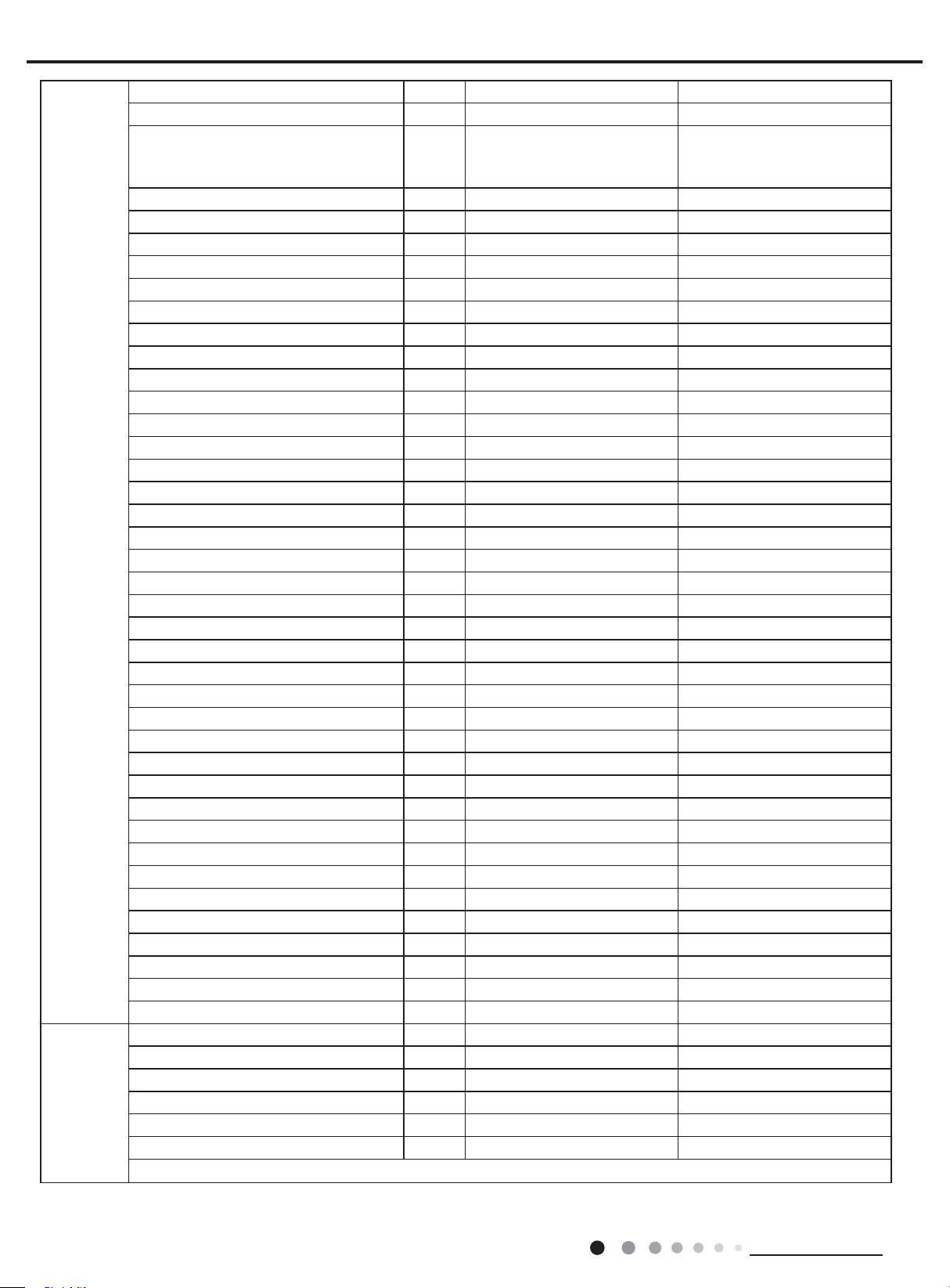
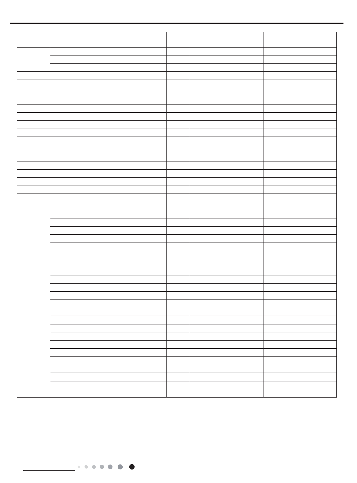
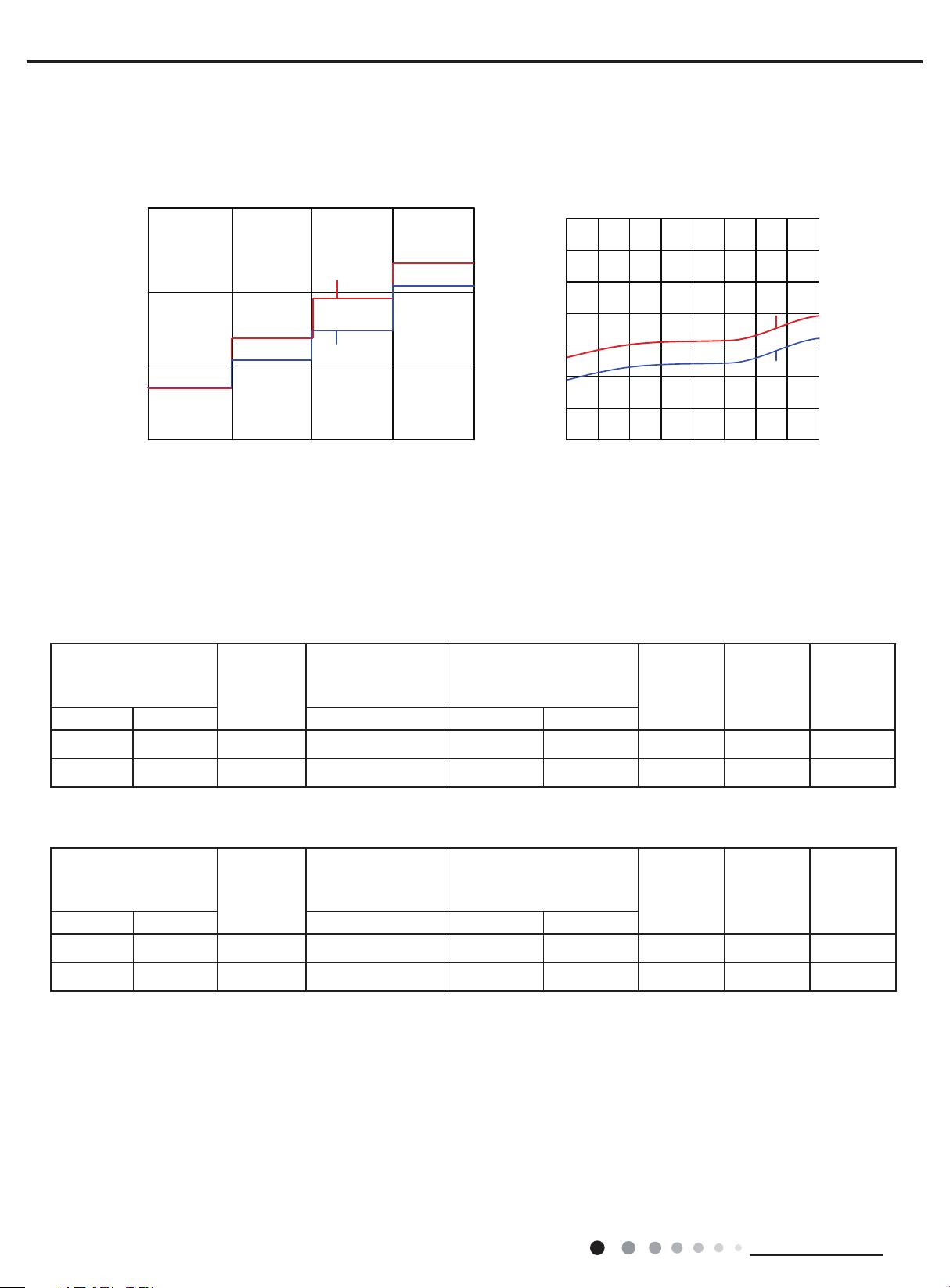
2.2 Capacity Variation Ratio According to Temperature
Heating operation ambient temperature range is -4ºF~75ºF
105
100
95
90
85
80
75
70
65
60
55
50
90 95 100 105 110
Conditions
Indoor:
DB 80°F
WB66
Indoor air flow: Super High
Pipe length :
24.6ft
°F
Outdoor temp. (˚F
Heating operation ambient temperature range is -31ºF~75ºF
Cooling Heating
140
120
100
80
60
40
Capacity ratio (%)
20
0
0 14 23 32 59 68 77 86 95 104 109 115
Capacity ratio (%)
110
100
90
80
70
60
Capacity ratio (%)
50
40
-4 514
Conditions
Indoor:DB
Indoor air flow:Super High
Pipe length:
70°F
24.6ft
23 32 41 50
utdoor temp. (˚F)
140
120
100
80
60
40
20
0
-31-22 -13-4518 35 45 50 59 68
Technical Information
9
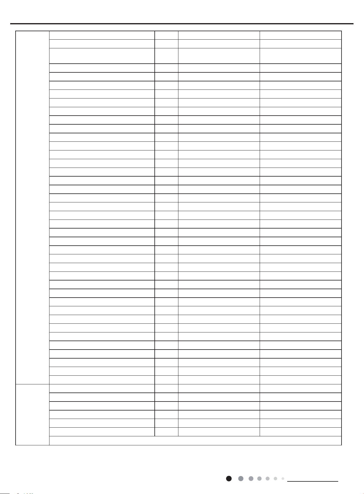
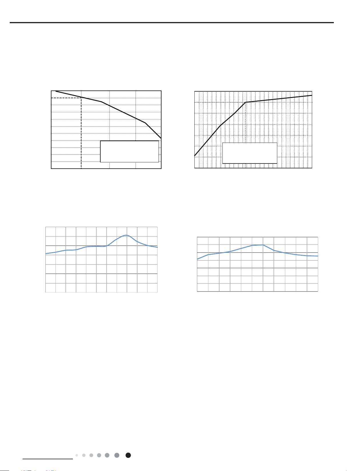
2.3 Noise Curve
Noise/dB(A)
Service Manual
Indoor side noise Outdoor side noise
60
50
40
30
36K
30K
LM
Indoor fan motor rating speed
HSH
80
75
70
65
60
Noise dB(A)
55
50
45
20 30 40 50 60 70 80 90 100
Compressor frequency(Hz)
36K
30K
2.4 Cooling and Heating Data Sheet in Rated Frequency
Cooling:
Rated cooling
condition(°F) (DB/WB)
Indoor Outdoor P (PSIG) T1 (°F) T2 (°F)
80/66 95/- 30K 130~145 46.8 to 52.8 127 to 96.8 Super High High 46
Model
Pressure of gas pipe
connecting indoor and
outdoor unit
Inlet and outlet pipe
temperature of heat
exchanger
Fan speed of
indoor unit
Fan speed of
outdoor unit
Compressor
revolution
(rps)
80/66
95/- 36K
Heating:
Rated heating
condition(°F) (DB/WB)
Indoor Outdoor P (PSIG) T1 (°F) T2 (°F)
70/- 20/19 30K 507~550 134.4 to 102 36 to 39 Super High High 46
70/- 20/19 36K 507~550 134.4 to 102 36 to 39 Super High High 34
Instruction:
T1: Inlet and outlet pipe temperature of evaporator
T2: Inlet and outlet pipe temperature of condenser
P: Pressure at the side of big valve
Connection pipe length: 24.6ft.
Model
130~145
Pressure of gas pipe
connecting indoor and
outdoor unit
46.8 to 52.8 127 to 96.8
Inlet and outlet pipe
temperature of heat
exchanger
Super High High
Fan speed of
indoor unit
Fan speed of
outdoor unit
37
Compressor
revolution
(rps)
10
Technical Information
Service Manual
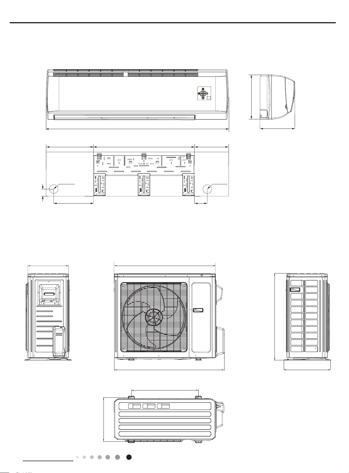
3. Outline Dimension Diagram
3.1 Indoor Unit
12 53/64
53 9/64
13 25/32 1029 3/8
Φ2 3/4
1 37/64
11 19/32
3.2 Outdoor Unit
GWC30LB-D3DNA3G/O VIRU30HP230V1AO
GWC36LB-D3DNA3G/O VIRU36HP230V1AO
14 37/64
10
Φ2 3/4
Unit:inch
3 1/2
36 2/9
Technical Information
15 9/16
39 1/2
24
31 7/64
16 13/16
Unit:inch
11
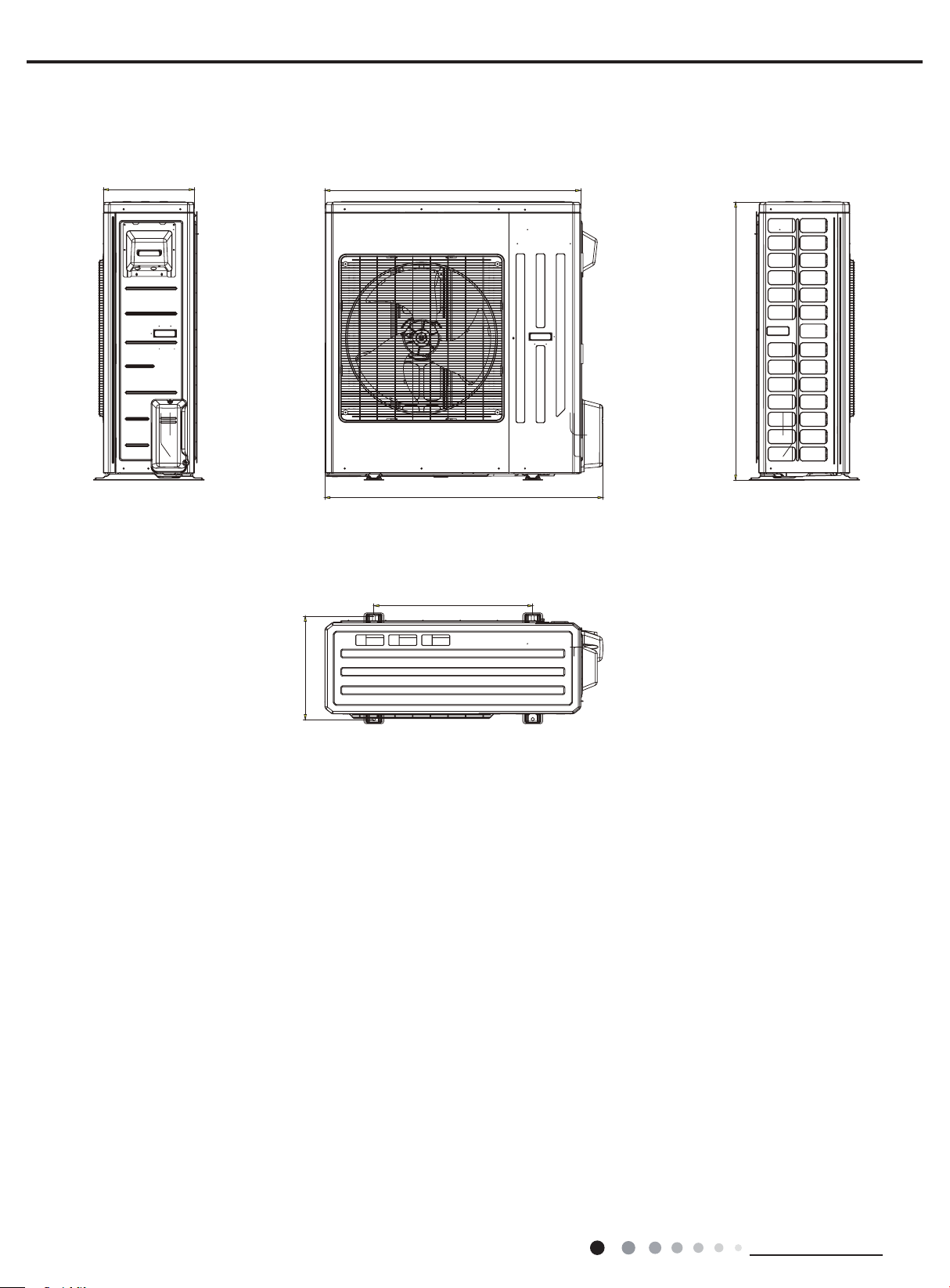
14 1/6
40
VIRU36HP230V1AO
VIRU30HP230V1AO
Service Manual
A
43 1/2
43 37/64
24 5/6
16 9/64
Unit:inch
12
Technical Information
Service Manual
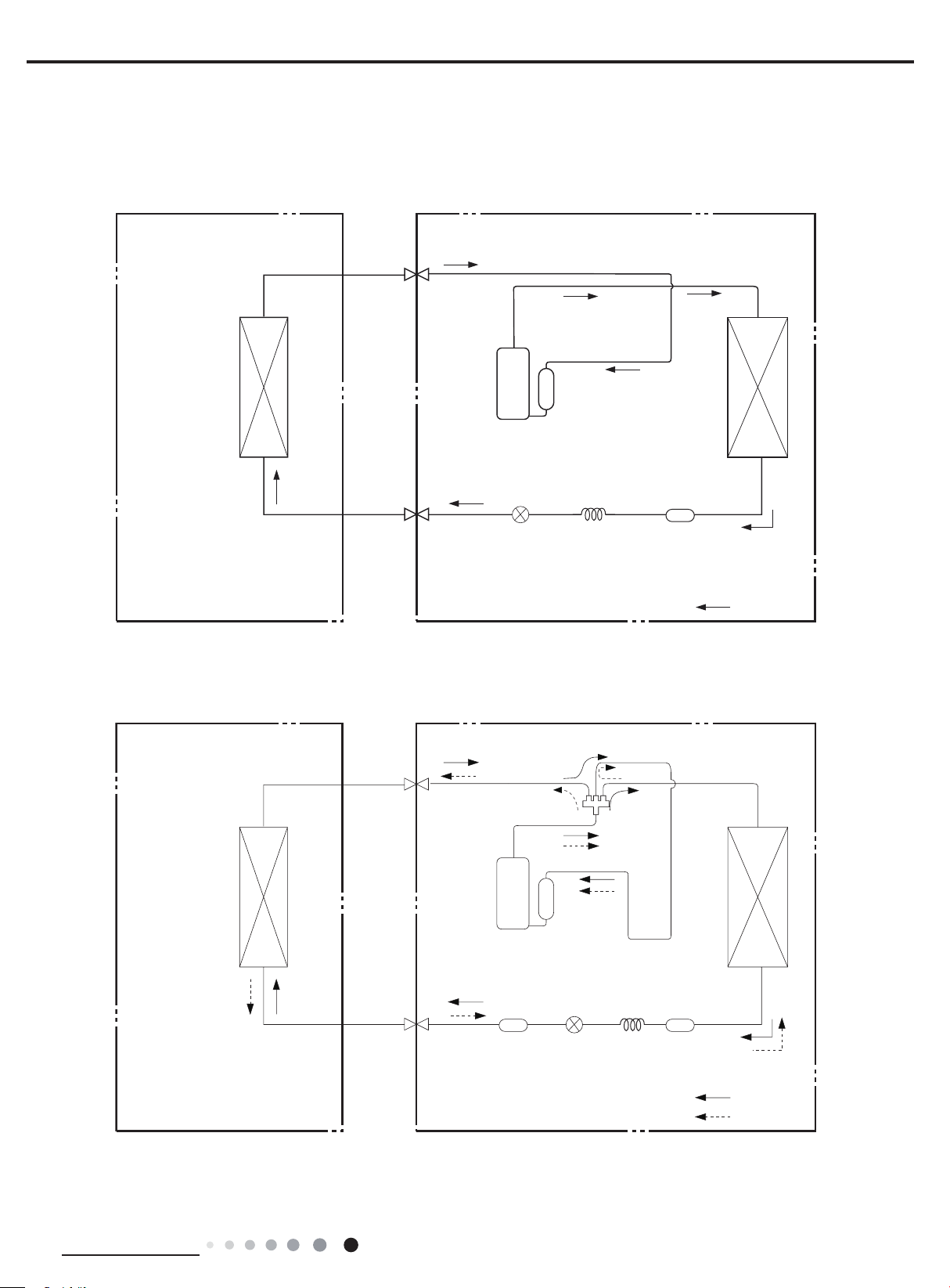
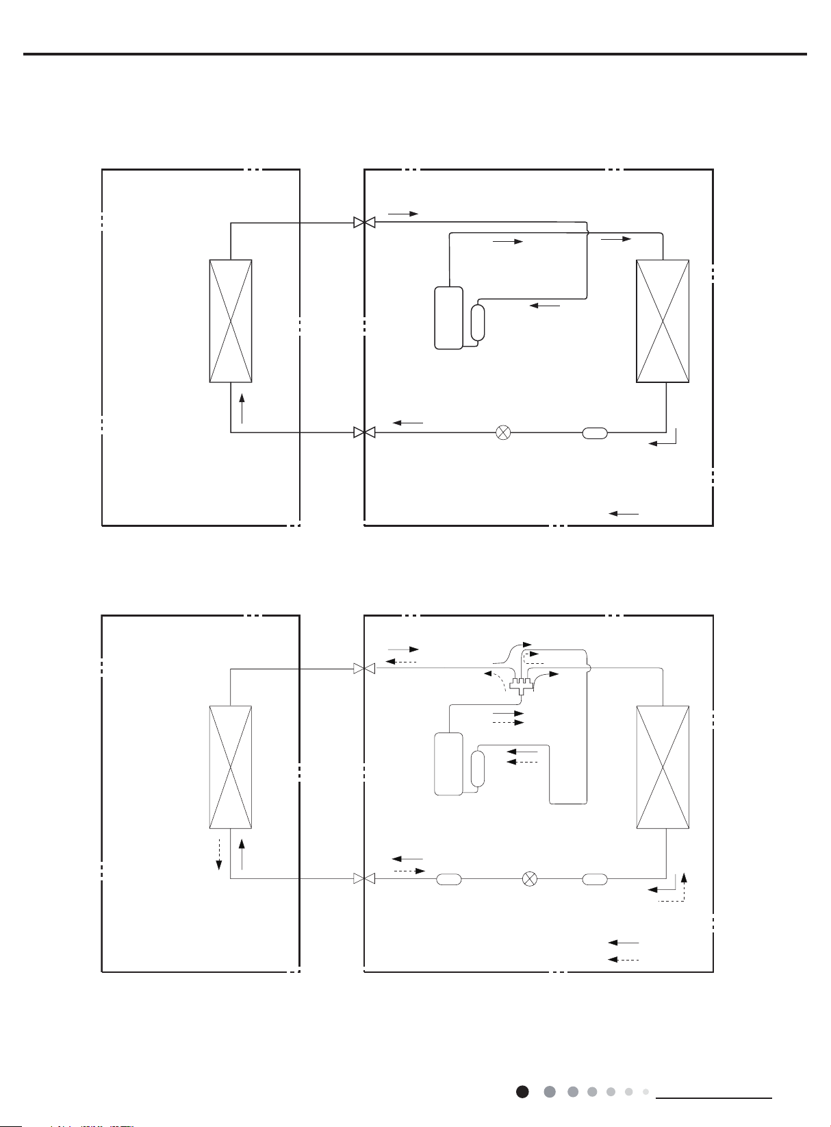
4. Refrigerant System Diagram
30K except :VIRU30HP230V1AH
Cooling only model
Indoor unit
Heat
exchanger
(evaporator)
Outdoor unit
Gas pipe
side
Valve
Discharge
Suction
Compressor
Accumlator
Heat
exchanger
Liquid pipe
(condenser)
side
Valve
Electron
expansion
valve
Capillary
Strainer
COOLING
Cooling and heating model
Indoor unit
Heat
exchanger
(evaporator)
Gas pipe
side
Valve
Liquid pipe
side
Valve
Discharge
Suction
Compressor
Strainer
Outdoor unit
4-Way valve
Accumlator
Electron
expansion
valve
Capillary
Heat
exchanger
(condenser)
Strainer
COOLING
HEATING
Connection pipe specication:
Liquid pipe:1/4 inch
Gas pipe:5/8 inch
Technical Information
13
36K except VIRU36HP230V1AH :
Indoor unit
Outdoor unit
Cooling only model
Service Manual
Gas pipe
side
Valve
Heat
exchanger
(evaporator)
Cooling and heating model
Indoor unit
Liquid pipe
side
Valve
Gas pipe
side
Valve
Discharge
Suction
Compressor
Electron
expansion
valve
Accumlator
Heat
exchanger
(condenser)
Strainer
COOLING
Outdoor unit
4-Way valve
14
Heat
exchanger
(evaporator)
Connection pipe specication:
Liquid pipe:1/4 inch
Gas pipe:5/8 inch
Liquid pipe
side
Valve
Discharge
Suction
Compressor
Strainer
Accumlator
Electron
expansion
valve
Heat
exchanger
(condenser)
Strainer
COOLING
HEATING
Technical Information
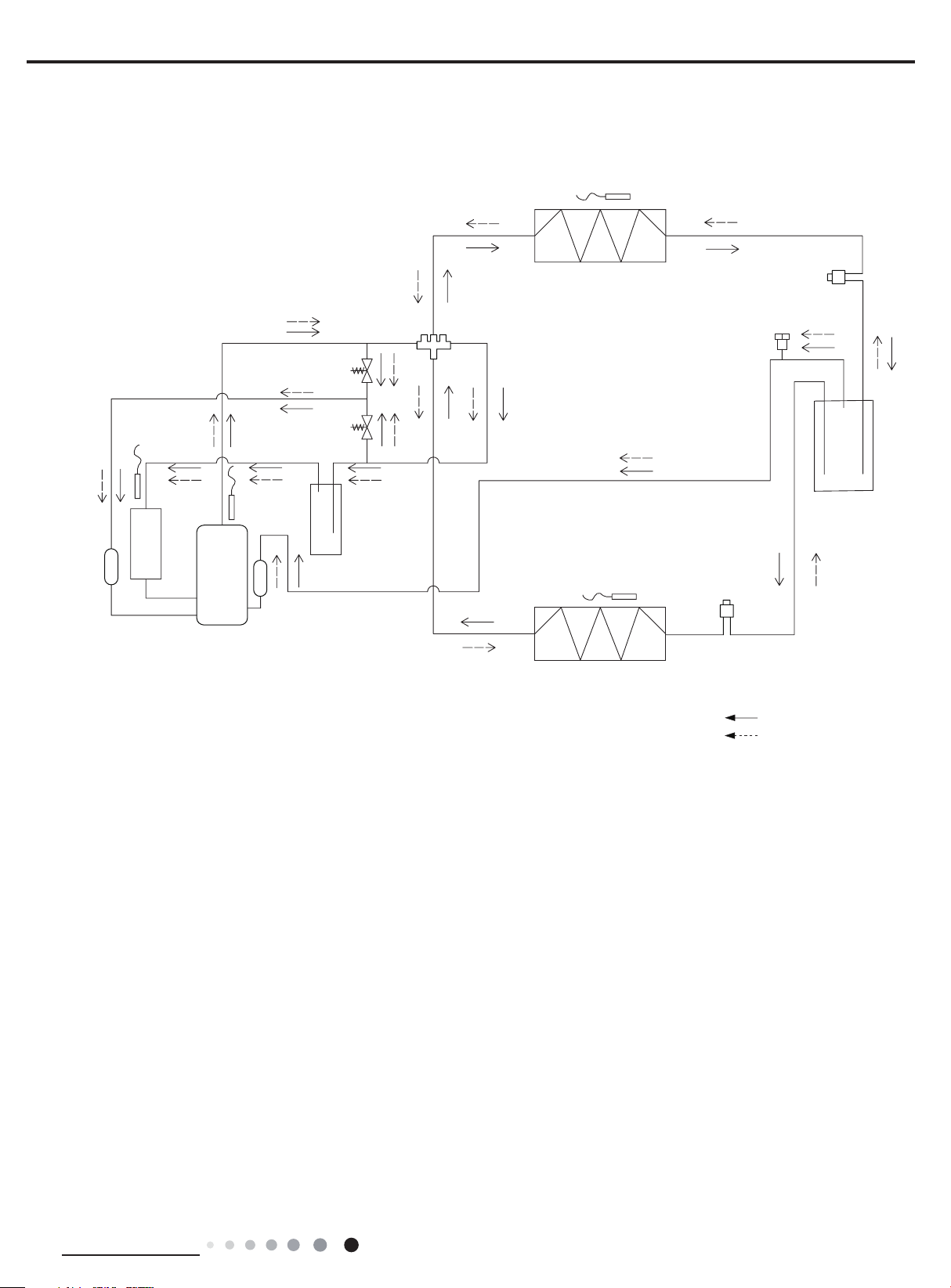
Service Manual
Variable
volume
VIRU36HP230V1AH
Gas-liquid
separator
VIRU30HP230V1AH
Solenoid valve
(high pressure)
Solenoid valve
(low pressure)
Gas-liquid
separator
4-way valve
Outdoor evaporator
Electronic
expansion
valve A
Unloading valve
Flash vaporizer
Compressor
Connection pipe specication:
Liquid pipe:1/4 inch
Gas pipe:5/8 inch
Air injection
Indoor evaporator
Electronic
expansion
valve B
COOLING
HEATING
Technical Information
15
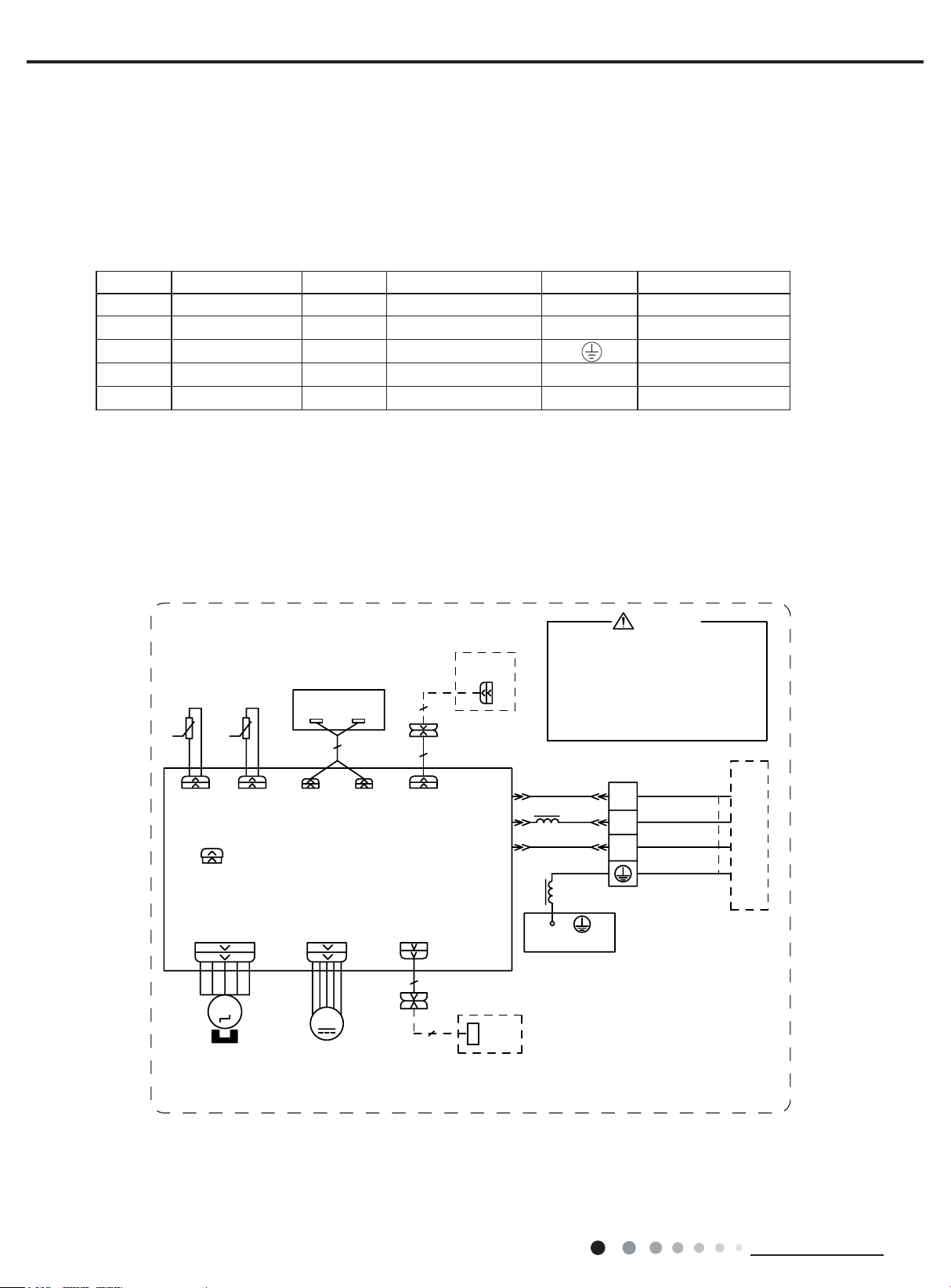
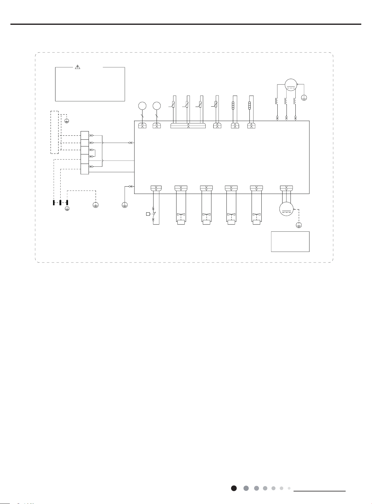
5. Electrical Part
5.1 Wiring Diagram
● Instruction
Symbol Symbol Color Symbol Symbol Color Symbol Name
WH White GN Green CAP Jumper cap
YE Yellow BN Brown COMP Compressor
RD Red BU Blue Grounding wire
YEGN Yellow/Green BK Black / /
VT Violet OG Orange / /
Note: Jumper cap is used to determine fan speed and the swing angle of horizontal lover for this model.
Service Manual
● Indoor Unit
5(&(,9(5$1'
',63/$<%2$5'
52207(03
6(1625
78%(7(03
6(1625
7575
78%(5220
&$3
-803
6:,1*8'
0$,1%2$5'
'&02725
$3
$3
',63',63
:,5('
&21752//(5
&211(&725
&200$18$/
&20287
:,),
$3
$&/
1
/
(9$325$725
:$51,1*
3OHDVHGRQWWRXFKDQ\
HOHFWURQLFFRPSRQHQWRU
WHUPLQDOZKHQWKHPDFKLQH
LVUXQQLQJVWRSSLQJRUKDV
EHHQSRZHUHGRIIIRUOHVV
WKDQPLQXWHVWRSUHYHQW
HOHFWULFVKRFN
7(50,1$/%/2&.
/
%8
%.
%1
<(*1
*
1
;7
:+%8
%.
5'%1
*1<(*1
287'22581,7
16
0
6:,1*
02725
0
)$102725
$3
63610000431
:,),02'8/(
Technical Information
Service Manual
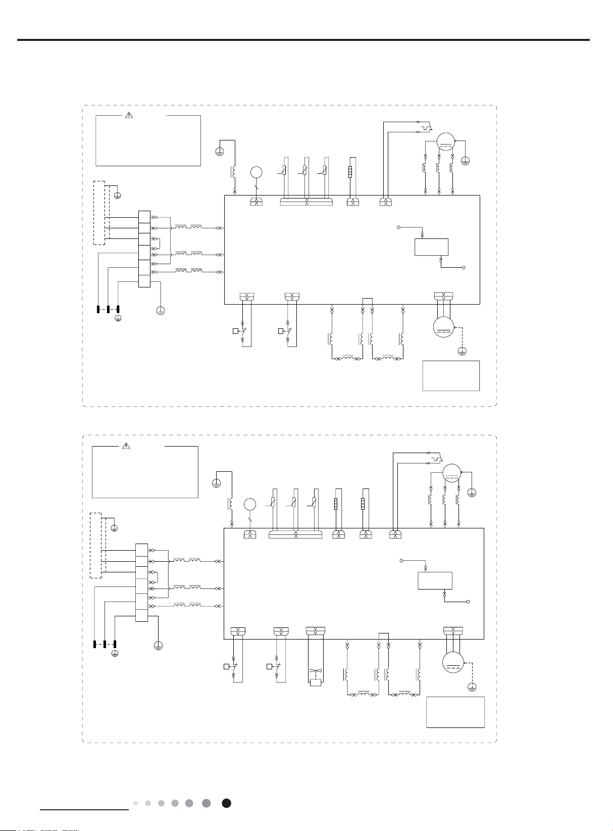
:9
● Outdoor Unit
GWC30LB-D3DNA3G/O GWC36LB-D3DNA3G/O
*1<(*1
*
:+%8
%.
5'%1
%.%1
:+%8
*1<(*1
:$51,1*
7(50,1$/
%/2&.
1
/
/
*
;7
%8
%1
<(*1
0$*1(7,&
/
/
/
*
5,1*
3OHDVHGRQWWRXFKDQ\
HOHFWURQLFFRPSRQHQWRU
WHUPLQDOZKHQWKHPDFKLQHLV
UXQQLQJVWRSSLQJRUKDVEHHQ
SRZHUHGRIIIRUOHVVWKDQ
PLQXWHVWRSUHYHQWWKHULVN
RIHOHFWULFVKRFN
,1'22581,7
//
32:(5
63610000470
29(5/2$'3527(&725
5'
$&/
/
6$7
0$*1(7,&
5,1*
%1
.
:+%1%8 <(
/
//
%8 <(
&20
<(*1
*
/
/
%.
/
%1
/
%8
(/(&7521,&
(;3$16,219$/9(
(.9
.
(
(9
&20
$&/
$&1
+3
35(6685(
03D 03D
35,17('&,5&8,7%2$5'
+33
33
+3
+,*+
6:,7&+
35(6685(
28778%(
7(036(1625
.
+33
*2*2:+ :+
+,*+
6:,7&+
7(036(1625
(;+$867
7(036(1625
2875220
575757
.
&1
&2035(6625
(+
+($7/
$3
/1 /1
//
/
5($&725
%$1'+($7(5
5'
29&&203
/3
/
5($&725
&203
*
8
&203
:
9
/
*
5'
89:
12
$&/
%1
2)$1'&
*
0
<(*1
)$1
02725
127(
0RWRUJURXQGRQO\
DSSOLHVWRWKH
LURQVKHOOPRWRU
<(*1
*
VIRU30HP230V1AO VIRU36HP230V1AO
:$51,1*
3OHDVHGRQWWRXFKDQ\
HOHFWURQLFFRPSRQHQWRU
WHUPLQDOZKHQWKHPDFKLQHLV
UXQQLQJVWRSSLQJRUKDVEHHQ
SRZHUHGRIIIRUOHVVWKDQ
PLQXWHVWRSUHYHQWWKHULVN
RIHOHFWULFVKRFN
*1<(*1
*
:+%8
%.
,1'22581,7
5'%1
%.%1
:+%8
*1<(*1
/ /
7(50,1$/
%/2&.
1
/
/
*
;7
%8
%1
<(*1
0$*1(7,&
/
/
/
*
5,1*
32:(5
6361000047001
<(*1
*
/
(
/
%.
&20
/
%1
$&/
/
%8
$&1
+33
+:+:2*2*
3 3
+3
+,*+
35(6685(
6:,7&+
03D 03D
(/(&7521,&
(.9
(9
7(036(1625
28778%(
2875220
7(036(1625
(;+$867
(;3$16,219$/9(
57 57 57
.
.
&1
7(036(1625
.
(+
%$1'+($7(5
&2035(6625
(+
$3
35,17('&,5&8,7%2$5'
:$<
7979
<9
:$<
9$/9(
/1
/ /
+3
35(6685(
6:,7&+
+33
+,*+
%27720
%$1'+($7(5
5'
+($7/+($7/
29&&203
/3
<( :+
/
5($&725
29(5/2$'3527(&725
6$7
8
0$*1(7,&
5'
$&/
%1%8
/
/
5($&725
5,1*
9
/ /
8%(<
8
%1
&20
12
.
/1
/
127(
0RWRUJURXQGRQO\
DSSOLHVWRWKH
LURQVKHOOPRWRU
&203
/
5'
%1
2)$1'&
0
)$1
02725
&203
*
:
*
$&/
*
<(*1
<(*1
*
Technical Information
17
VIRU36HP230V1AO VIRU30HP230V1AO
Service Manual
3OHDVHGRQWWRXFKDQ\
HOHFWURQLFFRPSRQHQWRU
WHUPLQDOZKHQWKHPDFKLQHLV
UXQQLQJVWRSSLQJRUKDVEHHQ
SRZHUHGRIIIRUOHVVWKDQ
PLQXWHVWRSUHYHQWWKHULVN
RIHOHFWULFVKRFN
*1<(*1
*
7(50,1$/
%/2&.
:+%8
%.
,1'22581,7
5'%1
%.%1
:+%8
/ /
*1<(*1
1
/
/
;7
%8
%1
*
32:(5
600007001457
:$51,1*
%.
%1
%8
<(*1
&203
*
8
&203
:
<(*1
/
*
5'
:98
(/(&7521,&
(/(&7521,&
(;3$16,219$/9($
(.9
(.9
)%
)$
&20,11(5
7(036(1625
28778%(
2875220
(;3$16,219$/9(%
57 57 57
.
7(036(1625
.
.
76(1625
(;+$867
%. %.:+
7(036(1625
68&7,21
7(036(1625
57
(+
.
6(1625
%27720
%$1'+($7(5
&2035(6625
(+
+($7& +($7%
0$*1(7,&
%$1'+($7(5
5,1*
/ /
9
<(%8
$3
$&/
1
+33
3(
3
+3
+,*+
35(6685(
6:,7&+
:+:+
*
35,17('&,5&8,7%2$5'
ZKLWH EOXH UHGJUHHQ
:$<
<9
:$<
9$/9(
&1
9797
<9
0$.(83
:$<
9$/9(
%8%8
&1
<9
/2:
35(6685(
:$<9$/9(
&1
%8%8
<9
+,*+
35(6685(
:$<9$/9(
2)$1
%8%8
02725
127(
0RWRUJURXQGRQO\
DSSOLHVWRWKH
LURQVKHOOPRWRU
0
)$1
*
<(*1
*
The above data is subject to change without notice. Please refer to the nameplate of the unit.
18
Technical Information
Service Manual
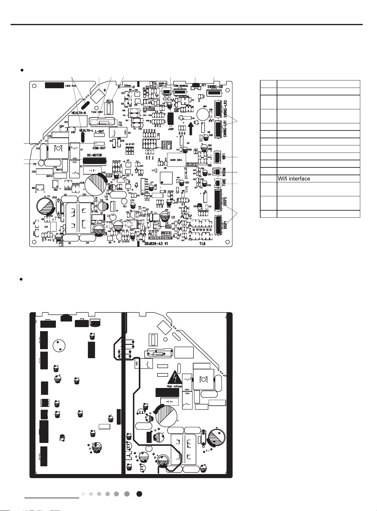
Top View
Interface of ambient temperature
5.2 PCB Printed Diagram
Indoor Unit
4567 8910
3
2
1
11
12
13
14
15
1Grounding wire
2 DC motor needle stand
Communication terminal for
3
outdoor unit
Interface of health function(only
4
for the mode with this function)
5Interface of neutral wire
6Fuse
7Interface of live wire
8 Needle stand for jumper cap
9Auto button
10 up&down swing interface
11 Left&right swing interface
12
13
sensor
Interface of tube temperature
14
sensor
15 Display interface
Bottom View
Technical Information
19
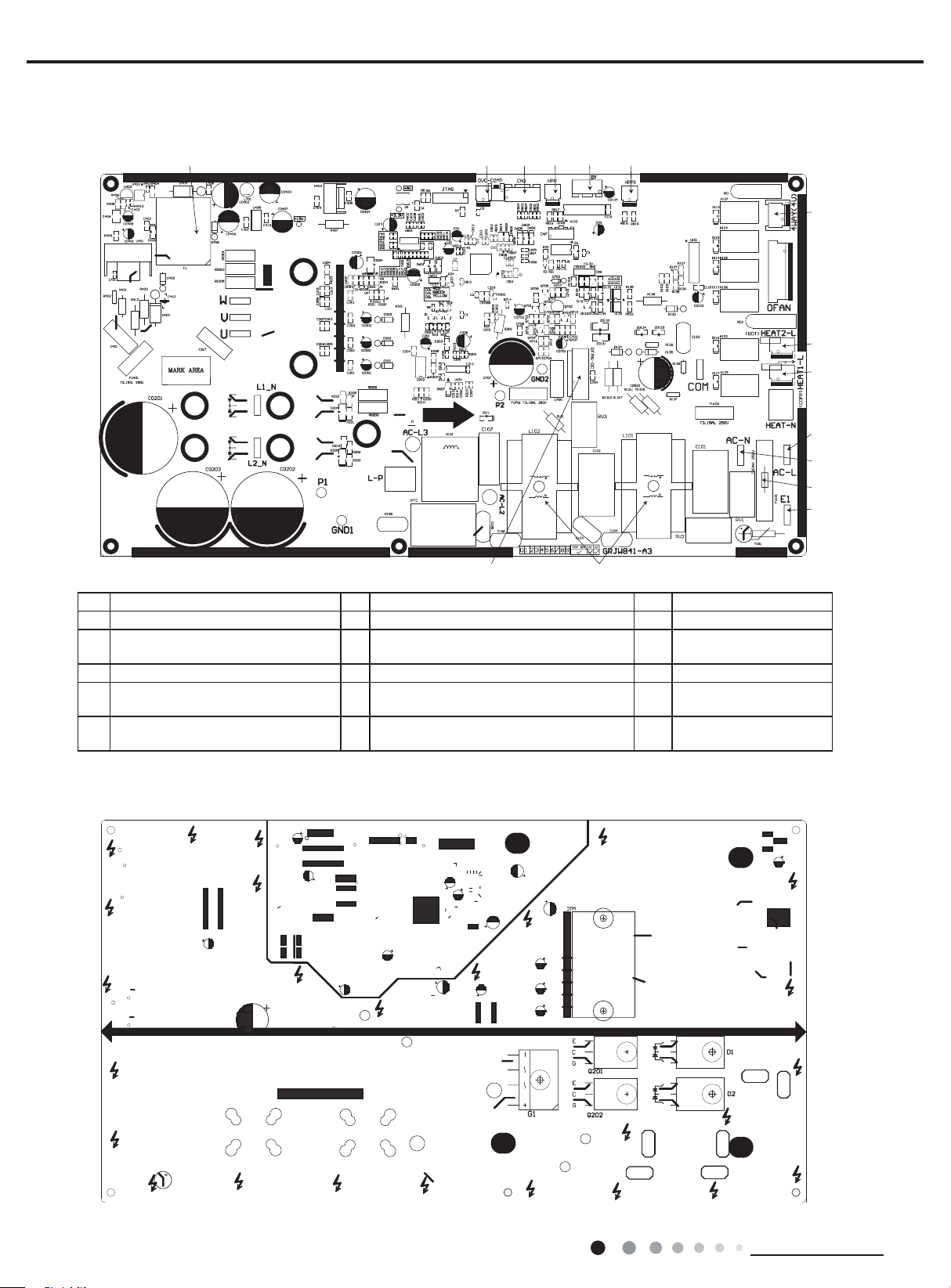
Outdoor Unit
1 2345 6
10
12
13
GWC30LB-D3DNA3G/O VIRU30HP230V1AO
GWC36LB-D3DNA3G/O VIRU36HP230V1AO
● Top view
Service Manual
1415
No. Name No. Name No. Name
1 High-frequency transformer T1 6 High pressure protection terminal HPP1 11 Terminal of neutral wire
Overload protection terminal of
2
compressor OVC-COMP
3 Terminal of temp sensor CN2 8 Electric heater band of chassis HEAT2-L 13 Terminal of ground wire
High pressure protection terminal
4
HPP
Electronic expansion valve terminal
5
EV
7 Terminal of 4-way valve 12 Protective tube FU101
Electric heater band of compressor
9
HEAT1-L
10 Terminal of live wire 15
14 Choke L 101 and L102
Terminal of outdoor fan
OFAN-DC
7
8
9
11
● Bottom view
20
Technical Information
Service Manual
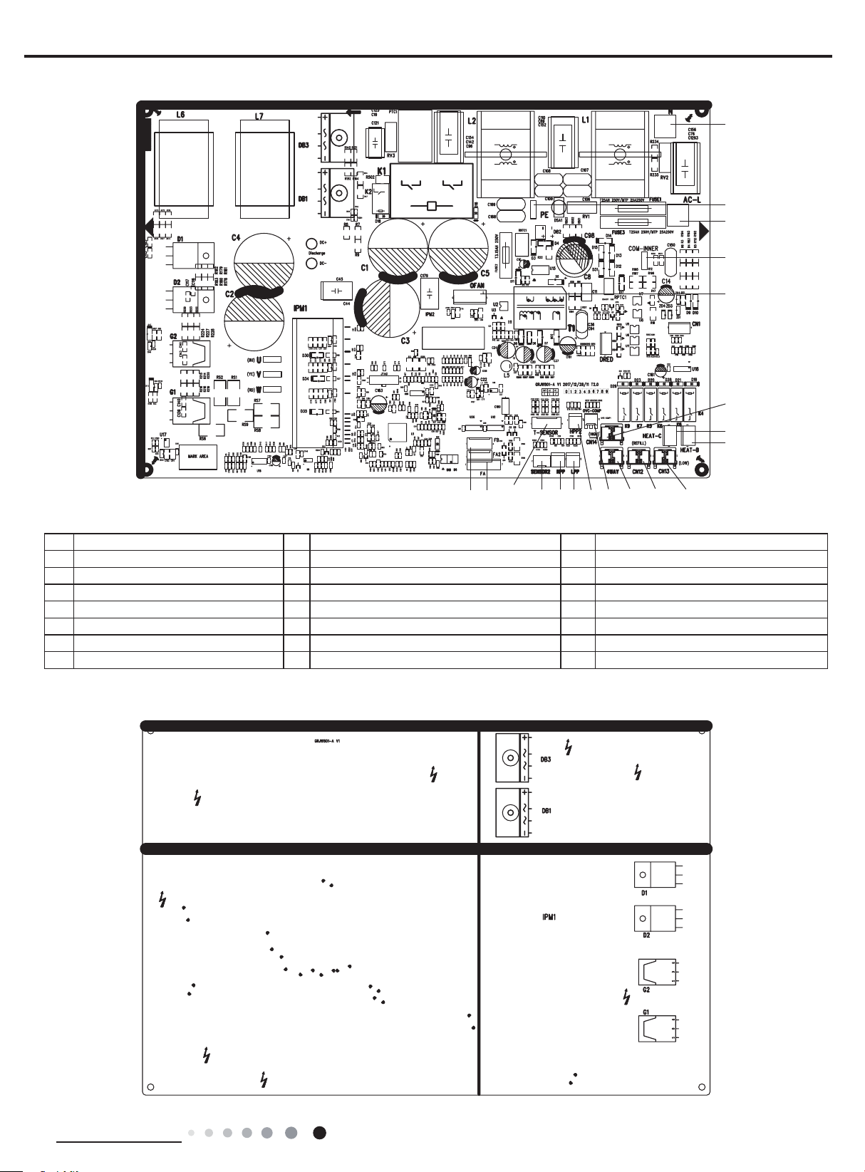
VIRU36HP230V1AO VIRU30HP230V1AO
1
2
3
4
5
6
7
8
1819 17 16 15 14 131211
No. Name No. Name No. Name
1 Neutral wire 8 Interface B of electric heating 15 Terminal for high pressure protection
2 Grounding wire 9 Terminal of low pressure valve 16 Interface 2 of temperature sensor
3 Live wire 10 Terminal of 2-way valve 17 Interface of temperature sensor
4 Communication interface 11 Terminal of 4-way valve 18 Terminal A of electronic expansion valve
5 Terminal of outdoor fan 12 Terminal of compressor overload protection 19 Terminal B of electronic expansion valve
6 Terminal of high pressure valve 13 Terminal for 2 high pressure protection
7 Interface C of electric heating 14 Terminal for low pressure protection
10
9
Technical Information
21
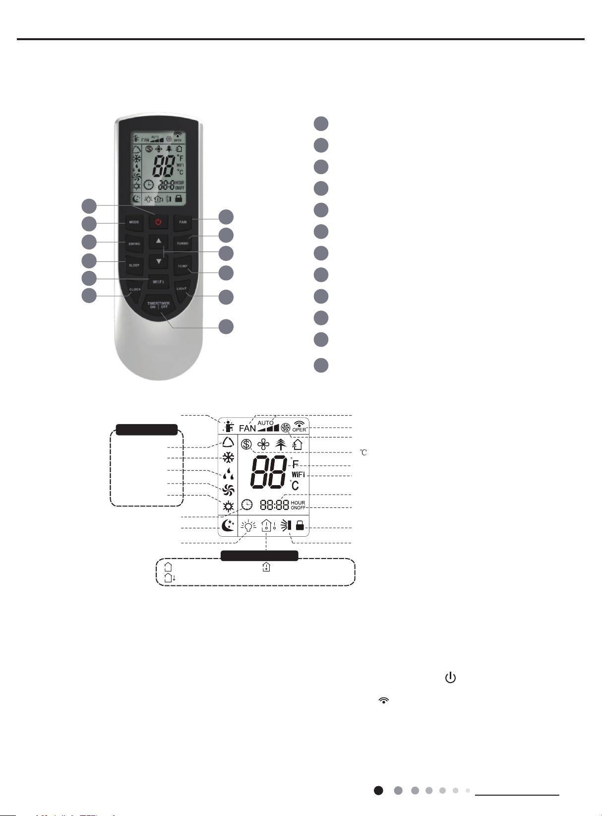
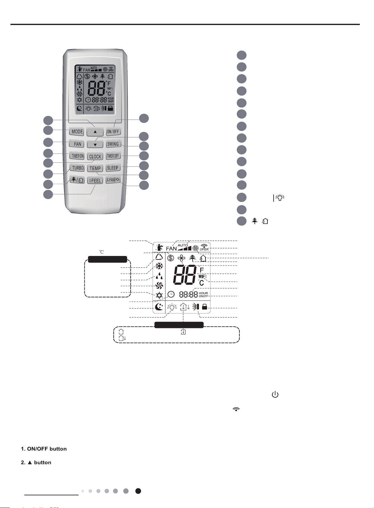
Introduction for icons on display screen
Introduction for buttons on remote controller
● Under of
time); Under on status, the display will show the corresponding set function icons.
● This is a general use remote controller, it could be used for the air conditioner
6. Function and Control
6.1 Remote Controller Introduction of YAN1F6F
ON/OFF button
1
MODE button
2
FAN button
3
SWING button
4
Service Manual
1
2
4
7
9
11
I feel
Operation mode
Auto mode
Cool mode
Dry mode
Fan mode
Heat mode
Clock
Sleep mode
Light
:Set temp.
:Outdoor ambient temp.
3
5
6
8
10
12
Temp. display type
:Indoor ambient temp.
Temp. di
splay type
TURBO button
5
▲
▲/ button
6
SLEEP button
7
TEMP button
8
WIFI button
9
LIGHT button
10
CLOCK button
11
TIMER ON / TIMER OFF
12
button
Set fan speed
Send signal
Turbo mode
8 heating function
Set temperature
WiFi function
Set time
TIMER ON /
TIMER OFF
Child lock
Up & down swing
Note:
which the model doesn't have, if press
original running status.
the corresponding button on the remote controller that the unit will keep the
tnereffid rof tnereffid si ruoloc eht models). After that, you can operate the air conditioner by using remote controller.
Under on status, pressing the button on the remote controller, the signal icon " "
will blink once and the air conditioner will give
conditioner.
f status, set temperature and clock icon will be displayed on the displa
off and light functions are set, the corre-
22
sponding icons will be displayed on the display of remote controller at the same
s
with multifunction; For some function,
Operation indicator " " is ON (red indicator, ● After putting through the power, .dnuos a tuo evig lliw renoitidnoc ria eht
on the display of remote controller ●
ria eht ot tnes neeb sah langis eht snaem hcihw ,dnuos ”ed“ a tuo
remit ,no remit fI( rellortnoc etomer fo y
Technical Information
Service Manual
ON/OFF button1.
2.
3.
Press this button again to exit turbo function and " " icon will disappear.
Press this button to turn on the unit. Press this button again to turn off the unit.
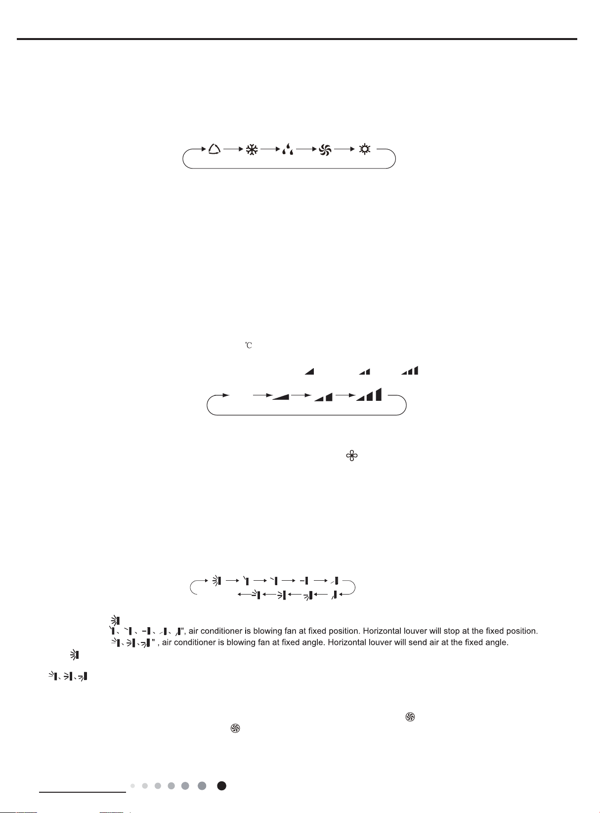
MODE button
Press this button to select your required operation mode.
FAN HEATAUTO COOL DRY
● When selecting auto mode, air conditioner will operate automatically according to ex-factory setting. Set temperature can’t be adjusted and
will not be displayed as well. Press "FAN" button can adjust fan speed. Press "SWING" button can adjust fan blowing angle.
● After selecting cool mode, air conditioner will operate under cool mode. Cool indicator on indoor unit is ON(This indicator is not available for
some models). Press "▲" or " " button to adjust set temperature. Press "FAN" button to adjust fan speed. Press "SWING" button to adjust fan
blowing angle.
● When selecting dry mode, the air conditioner operates at low speed under dry mode. Dry indicator on indoor unit is ON(This indicator is not
available for some models). Under dry mode, fan speed can’t be adjusted. Press "SWING" button to adjust fan blowing angle.
● When selecting fan mode, the air conditioner will only blow fan, no cooling and no heating. Press "FAN" button to adjust fan speed. Press
"SWING" button to adjust fan blowing angle.
● When selecting heating mode, the air conditioner operates under heat mode. Heat indicator on indoor unit is ON(This indicator is not
available for some models).Press "▲" or " " button to adjust set temperature. Press "FAN" button to adjust fan speed. Press "SWING" button
to adjust fan blowing angle. (Cooling only unit won’t receive heating mode signal. If setting heat mode with remote controller, press ON/OFF
button can’t start up the unit).
Note:
● For preventing cold air, after starting up heating mode, indoor unit will delay 1~5 minutes to blow air (actual delay time is depend on indoor
ambient temperature).
● Set temperature range from remote controller: 16~30
F
AN button
Pressing this button can set fan speed circularly as: auto (AUTO), low(
; Fan speed: auto, low speed, medium speed, high speed.
) ,medium( ), high(
).
Auto
Note:
● Under AUTO speed, air conditioner will select proper fan speed automatically according to ex-factory setting.
● Fan speed under dry mode is low speed.
● X-FAN function:Hold fan speed button for 2s in COOL or DRY mode, the icon “ ” is displayed and the indoor fan will continue operation
for a few minutes in order to dry the indoor unit even though you have turned off the unit. After energization, X-FAN OFF is defaulted. X-FAN
is not available in AUTO, FAN or HEAT mode.
This function indicates that moisture on evaporator of indoor unit will be blowed after the unit is stopped to avoid mould.
●Having set X-FAN function on:After turning off the unit by pressing ON/OFF button indoor fan will continue running for a few minutes.at low
speed.In this period,Hold fan speed button for 2s to stop indoor fan directly.
●Having set X-FAN function off: After turning off the unit by pressing ON/OFF button, the complete unit will be off directly.
4. SWING button
Press this button can select up&down swing angle. Fan blow angle can be selected circularly as below:
no display
(horizontal louvers stops at current position)
● When selecting " ", air conditioner is blowing fan automatically. Horizontal louver will automatically swing up & down at maximum angle.
● When selecting "
● When selecting "
● Hold " "button above 2s to set your required swing angle. When reaching your required angle, release the button.
Note:
● "
" may not be available. When air conditioner receives this signal, the air conditioner will blow fan automatically.
5. TURBO button
Under COOL or HEAT mode, press this button to turn to quick COOL or quick HEAT mode. "
Technical Information
" icon is displayed on remote controller.
23
6. ▲/▲ button
● Press "▲" or "
7.
9.
10.
12.
11
Press this button
n
actory
.
8.
that TIMER OFF is started up, press "TIMER OFF" button to cancel it.
remote controller will change quickly. On releasing button after setting is finished, temperature indica- tor on indoor unit will change
accordingly. (Temperature can’t be adjusted under auto mode)
● When setting TIMER ON, TIMER OFF or CLOCK, press "▲" or "▲" button to adjust time. (Refer to CLOCK, TIMER ON, TIMER OFF
buttons) When setting TIMER ON, TIMER OFF or CLOCK, press "▲" or "▲" button to adjust time. (Refer to CLOCK, TIMER ON, TIMER
OFF buttons)
SLEEP button
Under COOL, HEAT or DRY mode, press this button to start up sleep function. "
again to cancel sleep function and " " icon will disappear.
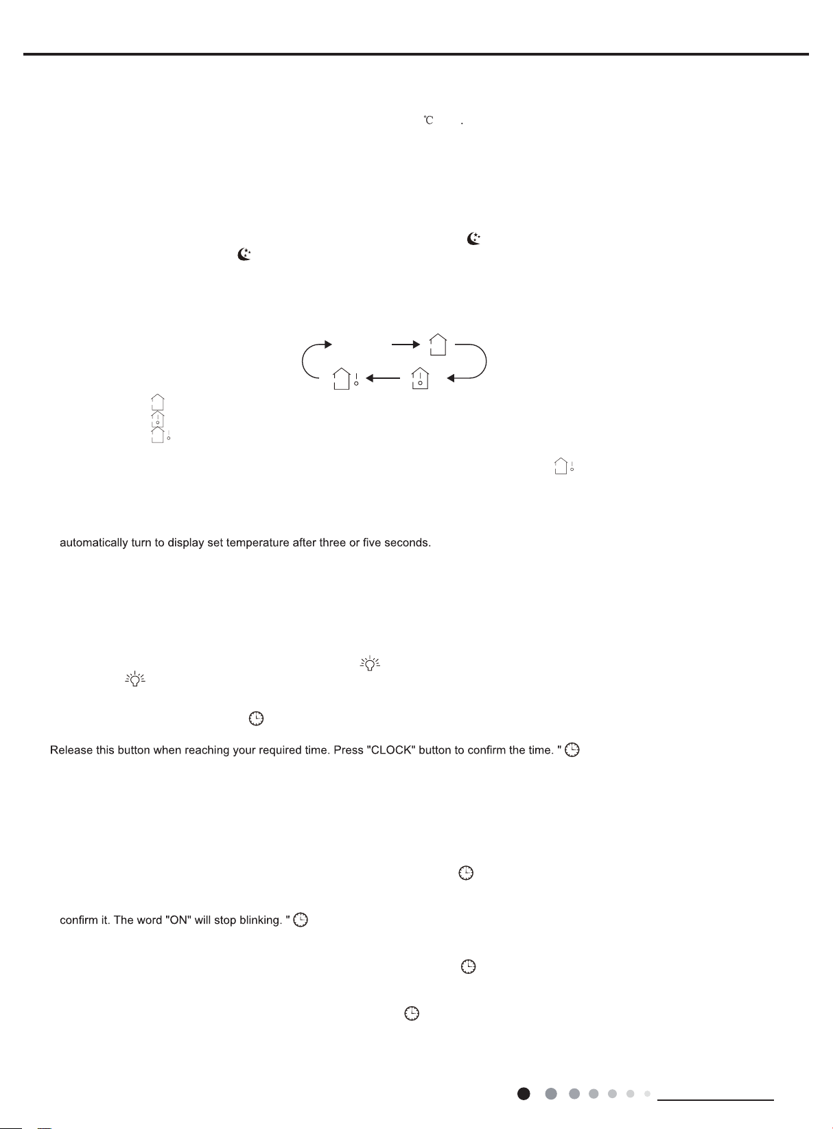
TEMP button
By pressing this button, you can see indoor set temperature, indoor ambient temperature or outdoor ambient temperature on indoor
display. The setting on remote controlleris selected circularly as below:
●
When selecting " " or no display with remote controller, temperature indicator on indoor unit displays set temperature.
●
When selecting " " with remote controller, temperature indicator on indoor unit displays indoor ambient temperature.
●When selecting "
Note:
●
Outdoor temperature display is not available for some models. At that time, indoor
temperature.
●
Its defaulted to display set temperature when turning on the unit.There is no display in the remote controller.
●
Only for the models whose indoor unit has dual-8 display.
When selecting displaying of indoor or outdoor ambient temperature, indoor temperature indicator displays corresponding tempe
●
▲
" button once increase or decrease set temperature 1
no display
" with remote controller, temperature indicator on indoor unit displays outdoor ambient temperature.
. Holding "▲" or "▲" button, 2s later, set temperature on
(1°F)
" icon is displayed on remote controller.
unit receives "
"signal, while it displays indoor set
Service Manual
units
rature and
WIFI button
Press " WiFi " button to turn on or turn off WiFi function. When WiFi function is turned on, the " WiFi " icon will be displayed on remote
controller; Under status of remote controller off, press "MODE" and " WiFi " buttons simultaneously for 1s,WiFi modulewill restore to f
default setting.
LIGHT button
Press this button to turn off display light on indoor unit. "
display light. " " icon is displayed.
.
CLOCK button
Press this button to set clock time. " " icon on remote controller will blink. Press "▲" or "
pressing of "▲" or "
Note:
Clock time adopts 24-hour mode.●
●
The interval between two operation cant exceeds 5s. Otherwise, remote controller will quit setting status. Operation for TIMER ON/TIMER
OFF is the same.
TIMER ON / TIMER OFF button
TIMER ON button
●
"TIMER ON" button can set the time for timer on. After pressing this button, "
blinks. Press "▲" or "
decrease 1min. Hold "▲" or "
started up, press "TIMER ON" button to cancel it.
● TIMER OFF button
"TIMER OFF" button can set the time for timer off. After pressing this button,"
controller blinks. Press "▲" or "
TIMER OFF setting will increase or decrease 1min. Hold "▲" or "
required time. Press "TIMER OFF" word "OFF" will stop blinking. " " icon resumes displaying. Cancel TIMER OFF. Under the condition
▲
" button, clock time will increase or decrease 1 minute. If hold "▲" or "▲" button, 2s later, time will change quickly
▲
"button to adjust TIMER ON setting. After each pressing "▲" or "▲" button, TIMER ON setting will increase or
▲
" button, 2s later, the time will change quickly until reaching your required time. Press "TIMER ON" to
" icon resumes displaying. Cancel TIMER ON: Under the condition that TIMER ON is
▲
" button to adjust TIMER OFF setting. After each pressing "▲" or "▲" button,
" icon on remote controller disappears. Press this button again to turn o
▲
" button within 5s to set clock time. Each
" icon stops blinking.
" icon disappears and the word "ON" on remote controller
" icon disappears and the word "OFF" on remote
▲
" button, 2s later, the time will change quickly until reaching your
24
Technical Information
Service Manual
Function introduction for combination buttons
1.
2.
according to setting time. ON/OFF button has no ef
3.
4.
Note:
● Under on and of
● Before setting
●
5.
rgy-saving
and
remote
Operation guide
1.
2.
3.
4.
5. Press "SWING" button to select fan blowing angle.
Press "▲" and "MODE" buttons simultaneously to start I FEEL
is
temperature
disappea
●
or
should be put within the area where indoor unit can receive the signal sent by the remote controller
f status, you can set TIMER OFF or TIMER ON simultaneously.
TIMER ON or TIMER OFF, please adjust the clock time.
After starting up TIMER ON or TIMER OFF, set the constant circulating valid. After that, air conditioner will be turned on or turned off
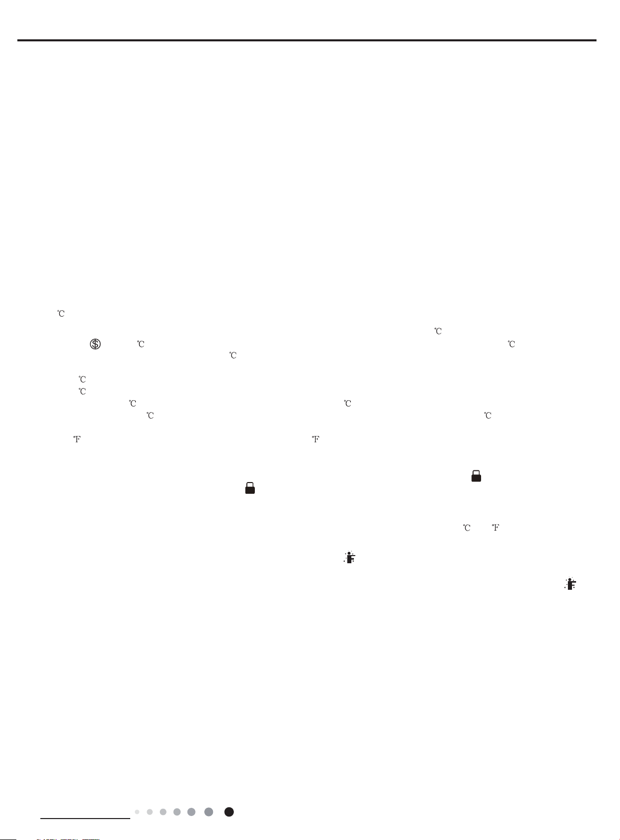
Energy-saving function
Under cooling mode, press "TEMP" and " CLOCK" buttons simultaneously to start up or turn off energy-saving function. When energy-saving
function is started up, "SE" will be shown on remote controller, and air conditioner will adjust the set temperature automatically according to
ex-factory setting to reach to the best energy-saving effect. Press "TEMP" and "CLOCK"buttons simultaneously again to exit ene
function.
Note:
● Under energy-saving function, fan speed is defaulted at auto speed and it cant be adjusted.
●
Under energy-saving function, set temperature cant be adjusted. Press "TURBO"
● Sleep function and energy-saving function cant operate at the same time. If energy-saving function has been set under cooling mode,
press sleep button will cancel energy-saving function. If sleep function has been set under cooling mode, start up the energy-saving
function will cancel sleep function.
8 heating function
Under heating mode, press "TEMP" and "CLOCK" buttons simultaneously to start
started up, " " and "8
"CLOCK" buttons simultaneously again to exit 8 heating function.
Note:
● Under 8
● Under 8
● Sleep function and 8
sleep button will cancel 8
cancel sleep function.
● Under
Child lock function
Press "▲" and "
controller. If you operate the remote controller, the " " icon will blink three times without sending signal to the unit.
heating function, fan speed is defaulted at auto speed and it cant be adjusted.
heating function, set temperature cant be adjusted. Press
temperature display, the remote controller will display 46 heating.
▲
" simultaneously to turn on or turn off child lock function. When child lock function is on, " " icon is displayed on
" will be shown on remote controller, and the air conditioner keep the heating status
heating function cant operate at the same time. If 8 heating function has been set under cooling mode, press
heating function. If sleep function has been set under cooling mode, start up the 8 heating function will
fect on setting. If you dont need this function, please use remote controller to cancel it.
button and the remote controller wont send signal.
up or turn off 8 heating function. When this function is
at 8 . Press "TEMP"
"
TURBO" button and the remote controller wont send signal.
Temperature display switchover function
Under OFF status, press "
I FELL Function
set, the remote controller will send the detected ambient temperature to the controller and the unitwill automatically adjust the indoor
Please put the remote controller near user when this function is set. Do not put the remote controller near the object of high temperature
low temperature in order to avoid detecting inaccurate ambient temperature.When I FEEL function is turned on, the remote controller
After putting through the power, press "ON/OFF" button on remote controller to turn on the air conditioner.
Press "MODE" button to select your required mode: AUTO, COOL, DRY, FA N, HEAT.
Press "▲" or "
Press "FAN" button to set your required fan speed: auto, low, medium and high speed.
according to the detected tempera-ture. Press this two buttons simultaneously again to close I FEEL function and " " will
r.
▲
" button to set your required temperature. (Temperature cant be adjusted under auto mode).
▲
" and "MODE" buttons simultaneously to switch temperature display between and .
function and " " will be displayed on the remote controller. After this function
Technical Information
.
25
Service Manual
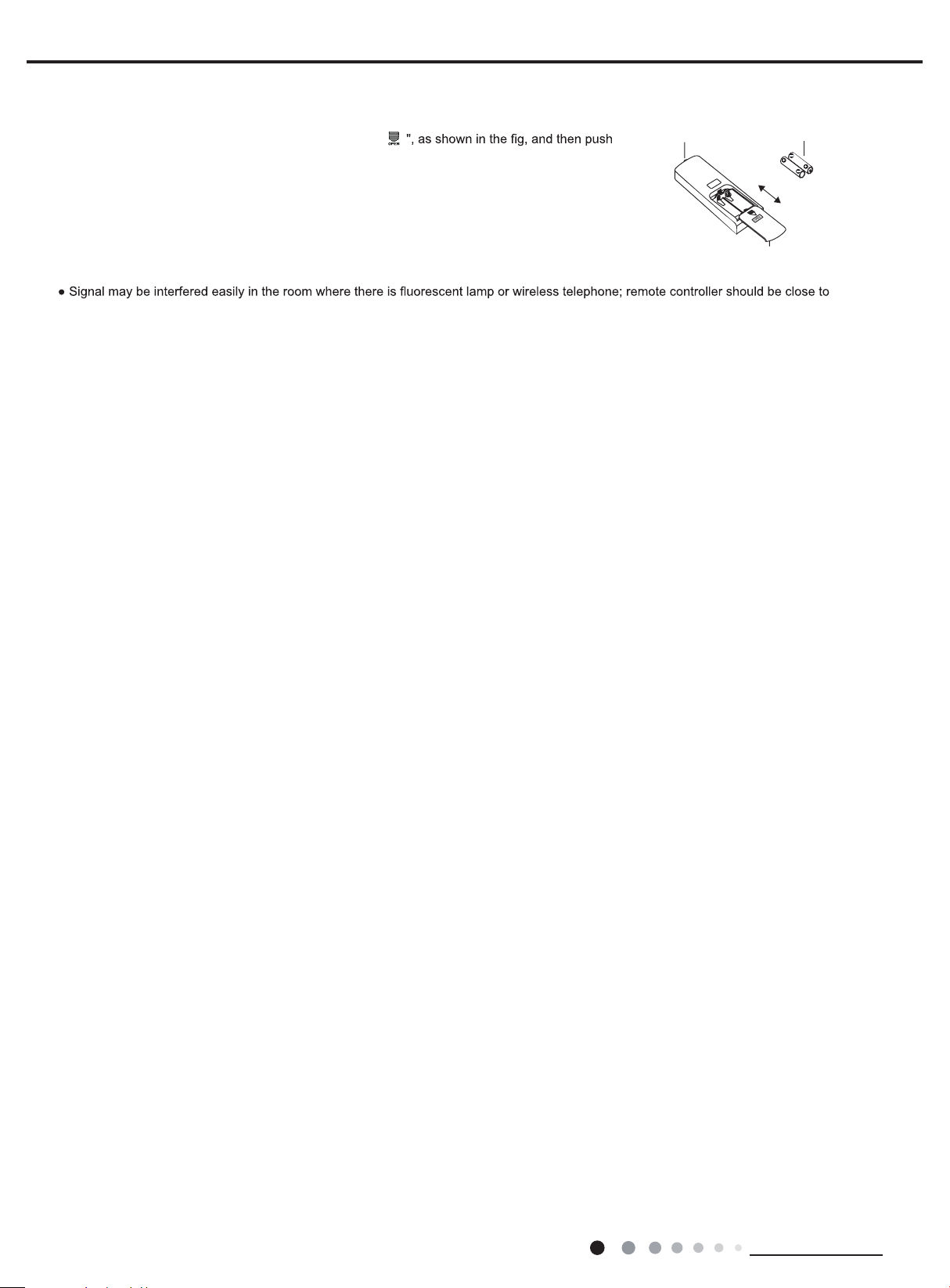
Replacement of batteries in remote controller
● During operation, point the remote control signal sender at the receiving window on indoor unit
●
hem.
indoor unit during operation.
● Replace new batteries of the same model when replacement is required.
● When you dont use remote controller for a long time, please take out the batteries.
● If the display on remote controller is fuzzy or theres no display, please replace batteries.
Press the back side of remote controller marked with "
1.
the cover of battery box along the arrow direction.
out
2.
Replace two 7# (AAA 1.5V) dry batteries, and make sure the position of "+" polar and "-" polar
are correct.
Reinstall the cover of battery box.3.
Note:
.
The distance between signal sender and receiving window should be no more than 8m, and there should be no obstacles between t
signal sender battery
reinstall
remove
Cover of battery box
26
Technical Information
Service Manual
Introduction for icons on display screen
1
2
5
4
6
7
8
11
12
13
9
14
15
ON/OFF button
▲ button
3
FAN button
SWING button
TIMER OFF button
TURBO button
10
TEMP button
I FEEL button
button
CLOCK button
TIMER ON button
SLEEP button
Send signal
Turbo mode
8
heating function
Set temperature
Set time
WiFi
TIMER ON /
TIMER OFF
Child lock
Up & down swing
Set fan speed
ventilation operation
Light
Temp. display type
:Set temp.
:Outdoor ambient temp.
:Indoor ambient temp.
Sleep mode
Clock
Heat mode
Fan mode
Dry mode
Cool mode
Auto mode
Operation mode
I feel
X-FAN button
/
MODE button
▲
button
X-fan mode
health function
Introduction for buttons on remote controller
Note:
●
●
After putting through the power, the air conditioner will give out a sound. Operation indicator " " is ON (red indicator,the
colout is different for different models). After that, you can operate the air conditioner by using remote controller.
●
Under on status, pressing the button on the remote controller, the signal icon " "
on the display of remote controller
will blink once and the air conditioner will give out a “de” sound, which means the signal has been sent to the air conditioner.
● Under off status, set temperature and clock icon will be displayed on the display
of remote controller (If timer on, timer
off and light functions are set, the corre-
sponding icons will be displayed on the display of remote controller at the same
time); Under on status, the display will show the corresponding set function icons.
Press this button to turn on the unit. Press this button again to turn off the unit.
Press this button to increase set temperature. Holding it down above 2 seconds rapidly increases set temperature.
In AUTO mode, set temperature is not adjustable.
14
3
1
13
2
6
9
8
12
15
4
7
10
5
11
This is a general use remote controller, it could be used for the air conditioners with multifunction; For some function, which the
model doesn't have, if press the corresponding button on the remote controller that the unit will keep the
original running status.
6.2 Remote Controller Introduction of YV1FB9F
Technical Information
27
 Loading...