

Gree UMAT24HP230V1AC, UMAT30HP230V1AC, UMAT36HP230V1AC, UMAT42HP230V1AC, UMAT48HP230V1AC Installation Manual
...
CEILING CASSETTE
INSTALLATION MANUAL
Models:
Indoor Unit Outdoor Unit
UMAT18HP230V1AC UMAT18HP230V1AO
UMAT24HP230V1AC UMAT24HP230V1AO
UMAT30HP230V1AC UMAT30HP230V1AO
UMAT36HP230V1AC UMAT36HP230V1AO
UMAT42HP230V1AC UMAT42HP230V1AO
UMAT48HP230V1AC UMAT48HP230V1AO

Table of Contents
Safety Precautions . . . . . . . . . . . . . . . . . . . . . . . . . . . . . . . . . . . . . . . . . . . . 2
Nomenclature . . . . . . . . . . . . . . . . . . . . . . . . . . . . . . . . . . . . . . . . . . . . . . . . 3
System Requirements . . . . . . . . . . . . . . . . . . . . . . . . . . . . . . . . . . . . . . . . . . 4
Suggested Tools . . . . . . . . . . . . . . . . . . . . . . . . . . . . . . . . . . . . . . . . . . . . . . 5
System Parts . . . . . . . . . . . . . . . . . . . . . . . . . . . . . . . . . . . . . . . . . . . . . . . . . 6
Standard Parts . . . . . . . . . . . . . . . . . . . . . . . . . . . . . . . . . . . . . . . . . . . . . . . . 7
Installation Site Instructions . . . . . . . . . . . . . . . . . . . . . . . . . . . . . . . . . . . 8-9
Indoor Unit Installation . . . . . . . . . . . . . . . . . . . . . . . . . . . . . . . . . . . . . 10 -12
Outdoor Unit Installation . . . . . . . . . . . . . . . . . . . . . . . . . . . . . . . . . . . . . . 13
Piping Installation . . . . . . . . . . . . . . . . . . . . . . . . . . . . . . . . . . . . . . . . . 14-17
Power & Wiring . . . . . . . . . . . . . . . . . . . . . . . . . . . . . . . . . . . . . . . . . . . 18-20
Controller Installation and Setup . . . . . . . . . . . . . . . . . . . . . . . . . . . . . 21-22
Ceiling Cassette Panel Display . . . . . . . . . . . . . . . . . . . . . . . . . . . . . . . . . . 22
Fresh Air Intake . . . . . . . . . . . . . . . . . . . . . . . . . . . . . . . . . . . . . . . . . . . . . . 23
Decorative Grille Installation . . . . . . . . . . . . . . . . . . . . . . . . . . . . . . . . . . . 24
Testing and Inspection . . . . . . . . . . . . . . . . . . . . . . . . . . . . . . . . . . . . . . 25-28
Troubleshooting . . . . . . . . . . . . . . . . . . . . . . . . . . . . . . . . . . . . . . . . . . . 29-30
Diagnostic Codes . . . . . . . . . . . . . . . . . . . . . . . . . . . . . . . . . . . . . . . . . . 31-33
Warranty . . . . . . . . . . . . . . . . . . . . . . . . . . . . . . . . . . . . . . . . . . . . . . . . . Back
Thank you for choosing a
Ceiling Cassette Ductless
Heat Pump System for your customer.
Please read this installation manual carefully before installing and starting up
the Ceiling Cassette Ductless System. Take a moment to fill out the product and
installation form on the back cover. Retain both the manual and installation
record for future reference.
SAFETY PRECAUTIONS
Please read the following before installation.
This is the safety alert symbol. It is used to alert you to potential
personal injury hazards. Obey all safety messages that follow this
symbol to avoid possible injury or death.
This mark indicates procedures which, if improperly performed,
might lead to the death or serious injury of the user.
This mark indicates procedures which, if improperly performed, might
possibly result in personal harm to the user, or damage to property.
Notice is used to address practices not related to personal injury.
General Safety Precautions
1. Instructions for installation and use of this product are provided by the manufacturer.
For proper operation, the system must be installed in accordance with this
installation manual.
2. Installation must be performed in accordance with local laws, regulations and
National Electrical Codes (NEC).
3. If refrigerant leaks while work is being carried out, ventilate the area. Do not allow
refrigerant to come in contact with a flame as it produces toxic gas.
4. Disconnect all electrical power to the indoor and outdoor units until the system is
ready for start-up and checkout.
5. When installing or repairing the system, use only R410A refrigerant. Do not
mix refrigerant with other gases. If air or other gas enter the refrigeration system,
the pressure inside the system may rise to an abnormally high value and cause
damage or injury.
This appliance is not intended for use by persons (including children) with reduced physical,
sensory or mental capabilities, or lack of experience and knowledge, unless they have been given
supervision or instruction concerning use of the appliance by a person responsible for their safety.
WARNING
CAUTION
NOTICE
WARNING
2
Indoor unit
Outdoor unit
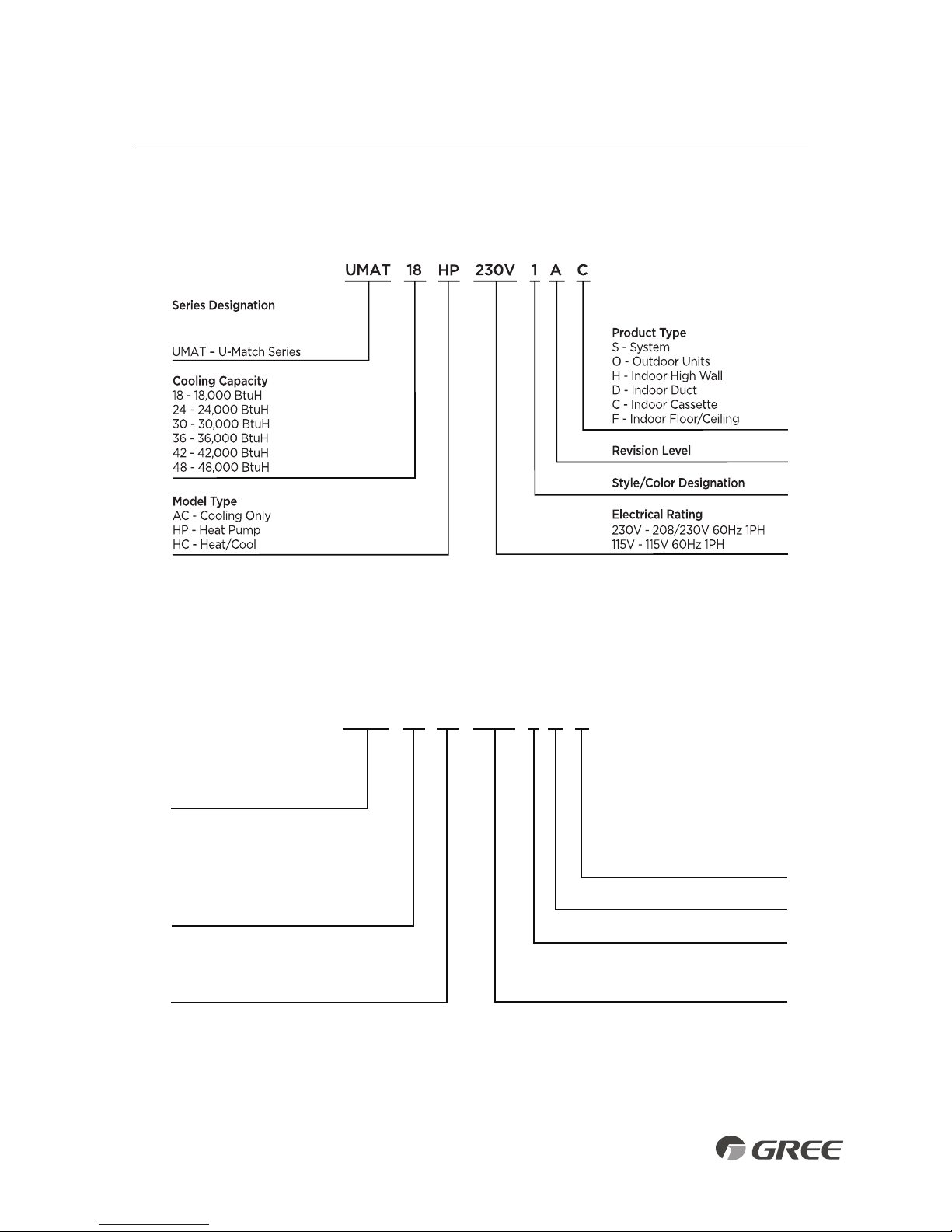
NOMENCLATURE
Example: UMAT18HP230V1AC
UMAT 18 1 A O
Series Designation
UMAT – U-Match Series
Product Type
S - System
O - Outdoor Units
H - Indoor High Wall
D - Indoor Duct
C - Indoor Cassette
F - Indoor Floor/Ceiling
Revision Level
Style/Color Designation
Electrical Rating
230V - 208/230V 60Hz 1PH
115V - 115V 60Hz 1PH
HP
230V
Cooling Capacity
18 - 18,000 BtuH
24 - 24,000 BtuH
30 - 30,000 BtuH
36 - 36,000 BtuH
42 - 42,000 BtuH
48 - 48,000 BtuH
Model Type
AC - Cooling Only
HP - Heat Pump
HC - Heat/Cool
Example: UMAT18HP230V1AO
3
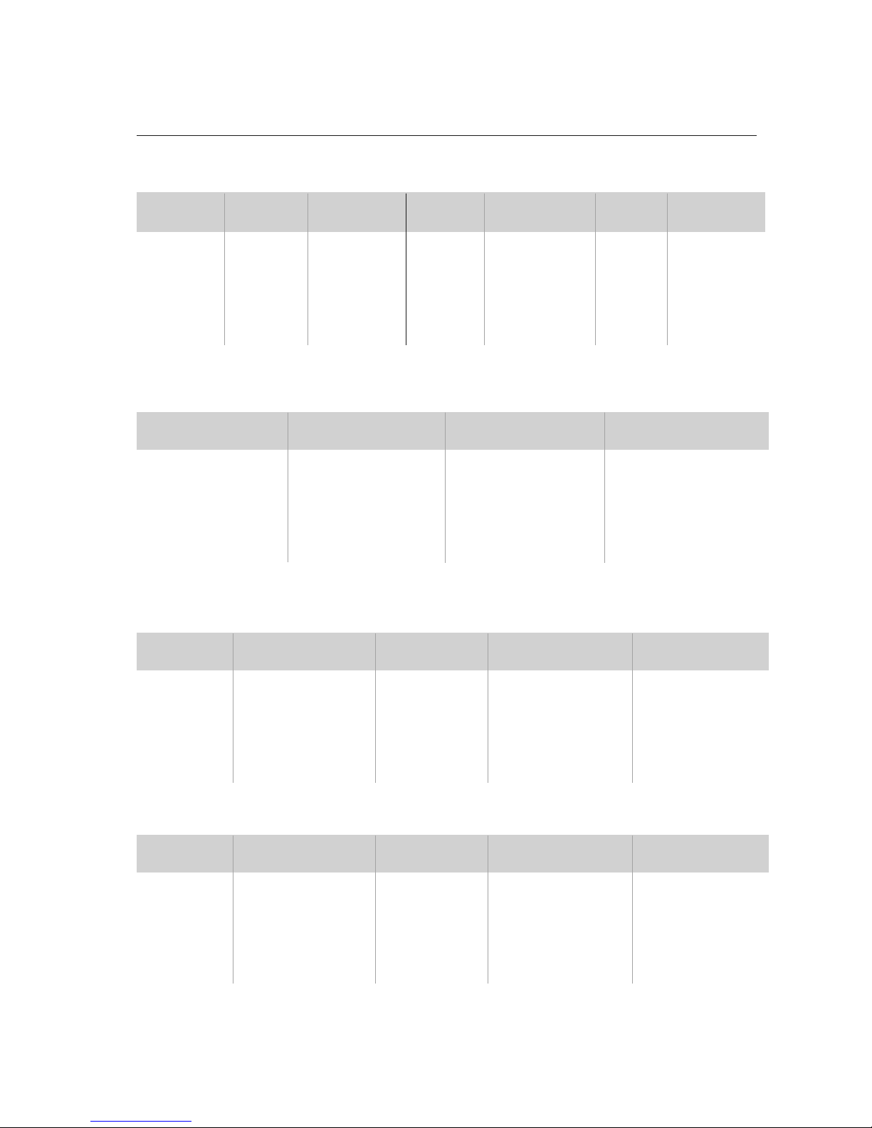
SYSTEM REQUIREMENTS
REFRIGERANT CHARGE
INDOOR UNIT ELECTRICAL REQUIREMENTS
PIPE SIZE in (mm)
Notes: Insulate both refrigerant lines, separately.
Communication Cable: Recommended cable - 18/2 AWG stranded bare copper conductors THHN 600V unshielded wire
Note: Use shield cable if installation is in close proximity of RF and EMI transmitting devices.
Unit Size
(BtuH)
18,000 1/4 (6) 1/2 (12) 10 (3) 25(7.5) 66 (20) 49 (15)
24,000 3/8 (10) 5/8 (15) 10 (3) 25(7.5) 98 (30) 49 (15)
30,000 3/8 (10) 5/8 (15) 10 (3) 25(7.5) 98 (30) 49 (15)
36,000 3/8 (10) 5/8 (15) 10 (3) 25(7.5) 98 (30) 49 (15)
42,000 3/8 (10) 5/8 (15) 10 (3) 25(7.5) 164 (50) 98 (30)
48,000 3/8 (10) 5/8 (15) 10 (3) 25(7.5) 164 (50) 98 (30)
Min Line
Max. Pre-Charge
Max Line
Max Elevation
Length
Line Length
Length
(ID over OD)
Liquid Suction/Gas
Line Line
Unit Size Refrigerant Factory System Additional
(BtuH) Type Charge oz (kg)* Charge oz/ft (g/m)
18,000 R410A 49.4 (1.4) 0.3 (30)
24,000 R410A 78.4 (2.2) 0.6 (60)
30,000 R410A 84.6 (2.4) 0.6 (60)
36,000 R410A 123.2 (3.6) 0.6 (60)
42,000 R410A 131.2 (3.8) 0.6 (60)
48,000 R410A 141.8 (4.1) 0.6 (60)
Unit Size
Voltage
Min Circuit Max Overcurrent Main Power
(BtuH) Amps (MCA) Protection (MOCP) Wire Size (AWG)
18,000 208/230v - 1ph 60hz 1.0 15 14
24,000 208/230v - 1ph 60hz 1.5 15 14
30,000 208/230v - 1ph 60hz 1.5 15 14
36,000 208/230v - 1ph 60hz 1.5 15 14
42,000 208/230v - 1ph 60hz 1.5 15 14
48,000 208/230v - 1ph 60hz 2.0 15 14
OUTDOOR UNIT ELECTRICAL REQUIREMENTS
Unit Size
Voltage
Min Circuit Max Overcurrent Main Power
(BtuH) Amps (MCA) Protection (MOCP) Wire Size (AWG)
18,000 208/230v - 1ph 60hz 17.0 25 10
24,000 208/230v - 1ph 60hz 24.0 40 10
30,000 208/230v - 1ph 60hz 24.0 40 10
36,000 208/230v - 1ph 60hz 29.0 45 8
42,000 208/230v - 1ph 60hz 31.0 50 8
48,000 208/230v - 1ph 60hz 45.0 70 6
*Precharge amount for up to 25-ft of refrigerant pipe.
REFRIGERANT LINE LENGTHS ft (m)
4
• Standard Wrench
• Adjustable/Crescent Wrench
• Torque Wrench
• Hex Keys or Allen Wrenches
• Drill & Drill Bits
• Hole Saw
• Pipe Cutter
• Screw drivers (Phillips & Flat blade)
• Manifold and Gauges
• Level
• R410A Flaring Tool
• Clamp on Amp Meter
• Vacuum Pump
• Safety Glasses
• Work Gloves
• Refrigerant Scale
• Micron Gauge
SUGGESTED TOOLS
5
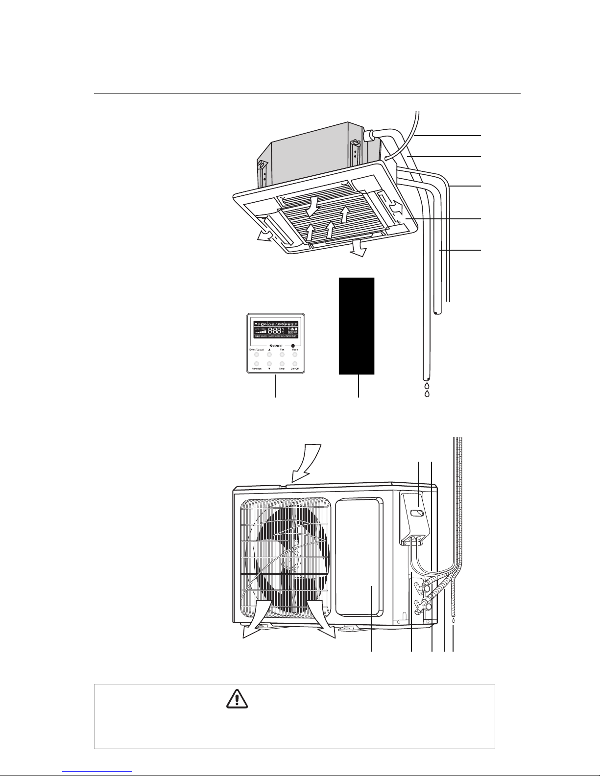
SYSTEM PARTS
Indoor unit
Part Name
1. Indoor Power Supply
2. Drain Pipe
3. Communication Cable
4. Decorative Discharge Air
Grille (sold separately)
5. Refrigeration Pipes
6. Wired Tether Controller
(sold separately)
7. Remote Controller
8. Service Cover
9. Communication Cable
10. Front Panel
11. Outdoor Power Supply
12. Liquid Pipe
13. Gas Pipe
14. Drain Hose
Outdoor Unit
Air outlet
Air inlet
1
2
5
4
3
67
6
Air outlet
Air inlet
14
12
1110
The refrigerant pipe, drain pipe and electrical wiring for this unit should be installed by a
qualified HVAC professional only.
CAUTION
98
13
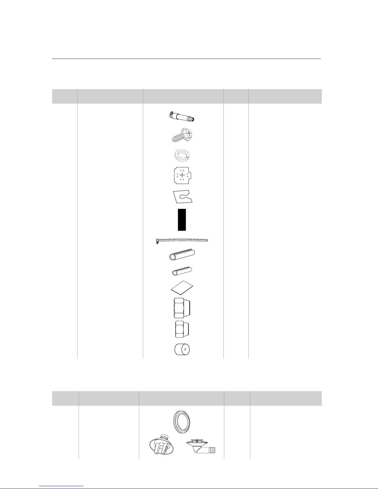
STANDARD PARTS
Indoor Unit Accessories
Outdoor Unit Accessories
No. Name Appearance Qty Usage
1 Drain Hose 1 Connects with field
supplied drain pipe
2 Screw with Washer 4 Secures the hook on the
cabinet of the unit
3 Washer 10 Used together with the hanger
bolt for installing the unit
4 Installation Template 1 Used for ceiling drilling
5 Gasket Mounting Board 4 Prevents gasket from
falling off
6 Remote Controller 1 Remotely controls the
indoor unit
7 Cable Clamp 4 Fastens the insulation to pipe
8 Pipe Insulation 1 Insulates the gas pipe
9 Pipe Insulation 1 Insulates the liquid pipe
10 Insulation 4
Insulates the drain pipe
11 Flare Nut 1 Connects the gas pipe
12 Flare Nut 1 Connects the liquid pipe
13 Service Valve Cap 2 Protects service port
7
No. Name Appearance Qty Usage
1 Drain Plug 2 or 3 Plugs the unused drain hole
2 Drainage Connecter
or
1
Connects with the hard
PVC drain pipe

INSTALLATION SITE INSTRUCTIONS
Indoor Unit
The unit must be installed in a location which can withstand four times the weight of the unit.
Inadequate support may result in serious property damage and injuries.
Select a site that allows for the following:
•
Ensure the installation complies with the installation minimum dimensions and meets the
minimum and maximum connecting piping length and maximum change in elevation.
• Air inlet and outlet should be clear of obstructions, ensuring proper airflow throughout the room.
• Condensate can be easily and safely drained.
• All connections can be easily made to outdoor unit.
• Indoor unit is out of reach of children.
• A structure strong enough to withstand four (4) times the full weight and vibration of the unit.
• Filter can be easily accessed for cleaning.
• Leave enough free space to allow access for routine maintenance.
• Do not install in a laundry room or by a swimming pool due to chemicals corroding cassette coil.
8
WARNING
Minimum Indoor Clearances
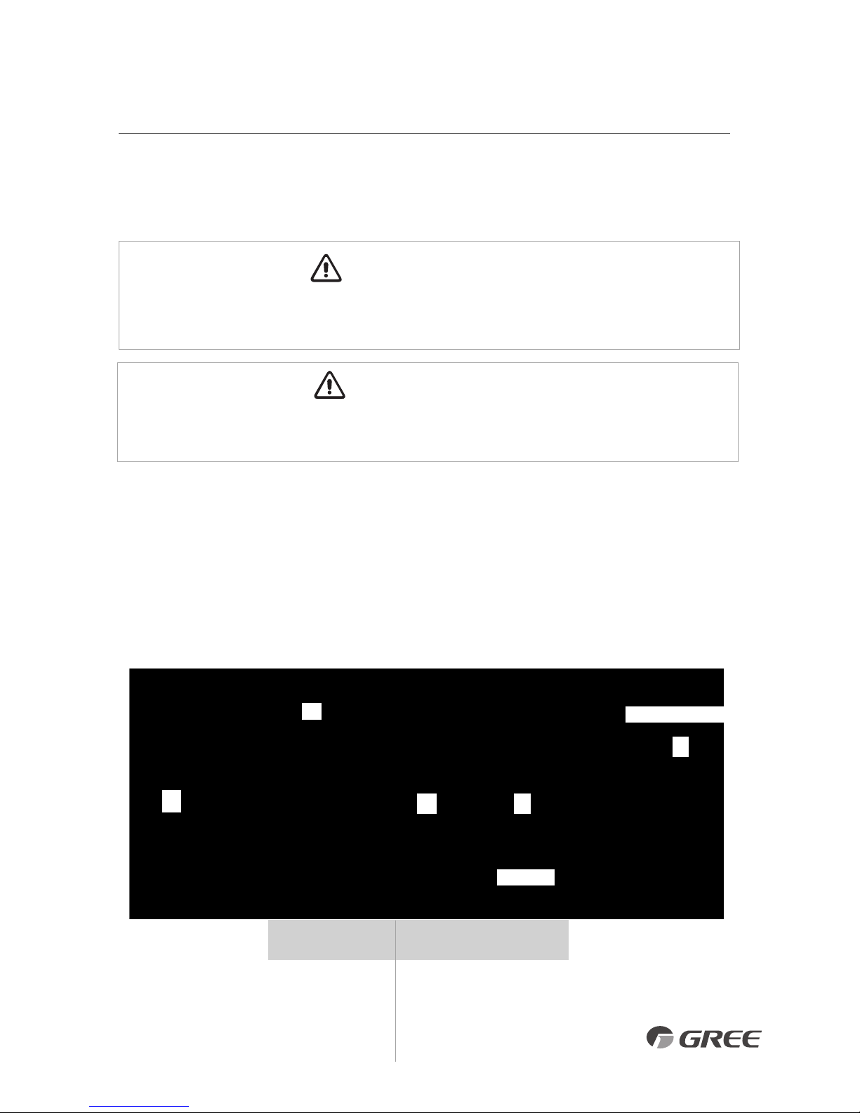
INSTALLATION SITE INSTRUCTIONS
Outdoor Unit
9
Do not install the unit at a location where the distance exceeds the maximum pipe length indicated
in
the table. The maximum length of the connection pipe is listed in the System Requirements section.
CAUTION
WARNING
Outdoor Unit
Minimum Distances
in (mm)
A 20 (500)
B 20 (500)
C 24 (610)
D 12 (305)
E 12 (305)
Air inlet
Air outlet
A
B
C D
E
The unit should be installed level on a pad that can support twice the weight of the unit.
If the outdoor unit will be exposed to strong winds, it must be adequately secured.
1. I
nstall the outdoor unit at a location that is capable of withstanding twice the weight of the unit.
2. Install the outdoor unit where it is convenient to connect refrigerant lines to the indoor unit.
3. I nstall the outdoor unit where the condensate water can be drained unobstructed during the
heating mode to a safe location.
4. Do not locate the unit where the noise may be objectionable to neighbors.
5. Provide the space shown below, so that the air flow is not blocked and future service and
maintenance can be performed.
Select a site that allows the following:
Minimum Outdoor Clearances
Model AB CDE F GH I
UMAT24HP230V1AC
37-3/8 32-3/4 30-3/4 26-3/4 6-1/4 9-1/2 36-1/8 8-1/2 39-1/8
(949) (832) (781) (679) (159) (241) (918) (216) (994)
UMAT30HP230V1AC
37-3/8 32-3/4 30-3/4 26-3/4 6-1/4 9-1/2 36-1/8 8-1/2 39-1/8
(949) (832) (781) (679) (159) (241) (918) (216) (994)
UMAT36HP230V1AC
37-3/8 32-3/4 30-3/4 26-3/4 6-1/4 9-1/2 36-1/8 8-1/2 39-1/8
(949) (832) (781) (679) (159) (241) (918) (216) (994)
UMAT42HP230V1AC
37-3/8 32-3/4 30-3/4 26-3/4 6-1/4 9-1/2 36-1/8 8-1/2 39-1/8
(949) (832) (781) (679) (159) (241) (918) (216) (994)
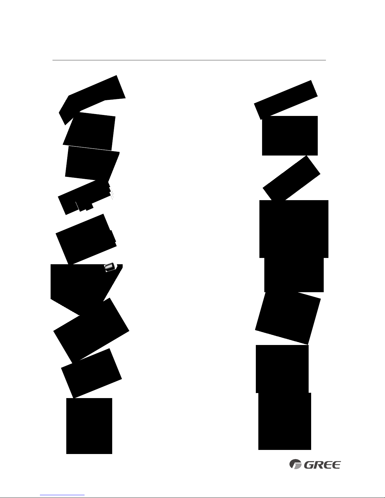
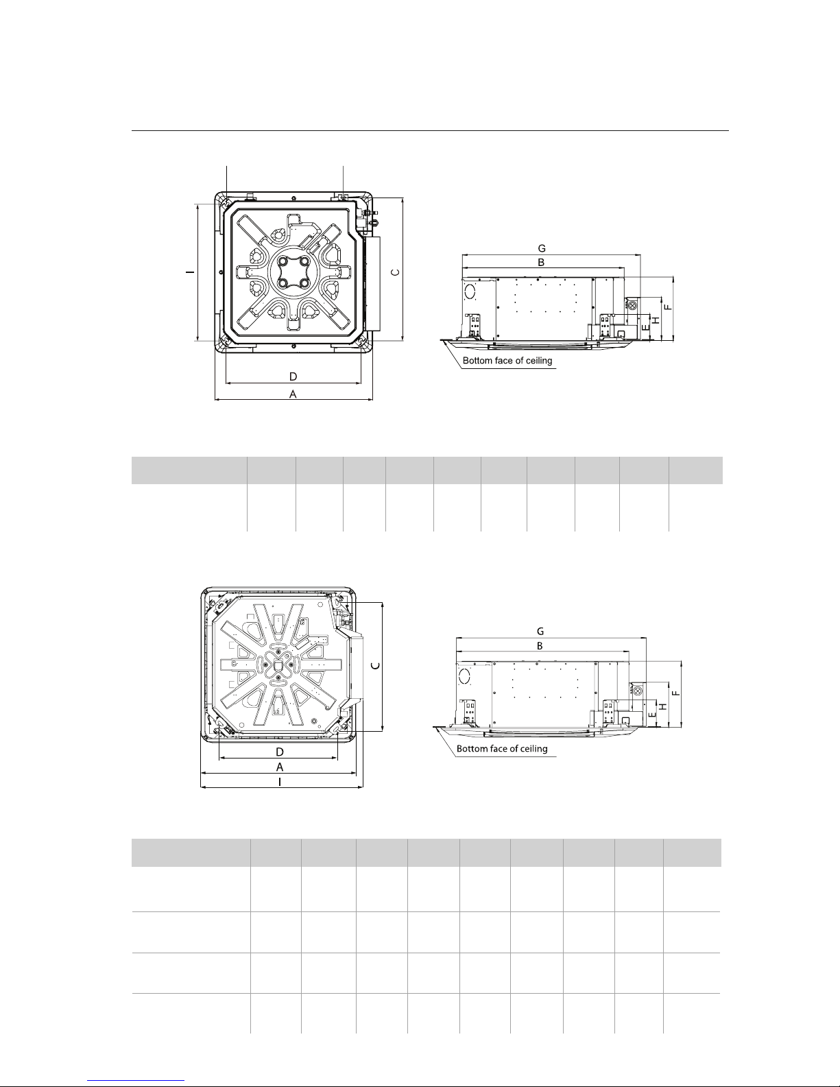
INDOOR UNIT DIMENSIONS in (mm)
10
INDOOR UNIT DIMENSIONS
Model ABCD E FGH I J
UMAT18HP230V1AC
26-3/8 23-1/2 23-1/4 22-5/8 5-3/4 9-1/2 26-1/8 9-1/4 22-5/8 19-7/8
(670) (597) (591) (575) (146) (241) (664) (235) (575) (505)
INDOOR UNIT DIMENSIONS in (mm)
18K Indoor Unit Dimensions
24K-42K Indoor Unit Dimensions
 Loading...