

Gree GRS-CQ12Pd/NaEK, GRS-CQ14Pd/NaEK, GRS-CQ14Pd/NaEM, GRS-CQ16Pd/NaEM, SXVD200LCJ/A-K Service Manual
...
Air-to-water Heat Pump Split Versati
Commercial AC R&D Department
Ⅰ
March , 2016

Contents
Product ........................................................................................................................................ 1
1. Product Data ........................................................................................................................... 1
1.1 Lineup ............................................................................................................................ 1
1.1.1 Main Unit .............................................................................................................. 1
1.1.2 Water Tank ........................................................................................................... 2
1.2 Nomenclature ................................................................................................................. 2
1.2.1 Main Unit .............................................................................................................. 2
1.2.2 Water Tank ........................................................................................................... 2
1.3 Product Features ............................................................................................................ 3
1.3.1 General ................................................................................................................ 3
1.3.2 Features ............................................................................................................... 3
1.4 Operating Principle ......................................................................................................... 4
1.4.1 Schematic Diagram .............................................................................................. 4
1.5 Technical Data ............................................................................................................... 5
1.5.1 Parameter List ...................................................................................................... 5
1.5.2 Nominal Working Conditions ................................................................................ 9
1.5.3 Operation Range .................................................................................................. 9
1.5.4 Electric Data ................................................................................................ ......... 9
1.5.5 Capacity Correction ............................................................................................ 10
2 Outline Dimensions ................................................................................................................ 11
2.1 Outline dimensions of outdoor unit ............................................................................... 11
2.2 Outline dimensions of indoor unit ................................................................................. 13
3 Explosive Views and Part Lists ............................................................................................... 14
4 Supply Scope ......................................................................................................................... 24
Design and Selection ................................................................................................................ 26
1 Installation Example ............................................................................................................... 26
2 Model Selection ...................................................................................................................... 28
2.1 Speculations of Power Supply ...................................................................................... 28
2.2 Operation Conditions .................................................................................................... 28
2.3 Flowchart of Model Selection........................................................................................ 29
2.4 Design Principle ........................................................................................................... 29
3 Selection of the Underfloor Coils ............................................................................................ 29
3.1 Calculation of Unit Load for Floor Heating .................................................................... 29
3.2 Selection of Tube Spacing of the Underfloor Coils ........................................................ 30
3.3 Selection of Loop Quantity of Coils for Each Room ...................................................... 30
3.3.1 Type of Underfloor Coils ..................................................................................... 30
3.3.2 Selection of Loop Quantity for Each Room ......................................................... 31
4 Quantity and Location of the Water Traps and Collectors ....................................................... 31
4.1 Design Requirements on Loop Quantity for Circulation Water ...................................... 31
4.2 Requirements on Installation of the Water Trap (Collector) .......................................... 33
5 Section of FCU ....................................................................................................................... 33
5.1 FCU Type Selection ..................................................................................................... 33
5.2 Matching of Capacity ................................................................ .................................... 33
6 Selection of the Water Tank ................................................................................................... 34

6.1 Specifications of the Water Tank .................................................................................. 34
6.2 Volume Selection of the Water Tank ............................................................................ 34
6.2.1 Selection Based on Water Consumption Per Capita ........................................... 34
6.2.2 Selection Based on Sanitary Utensils ................................................................. 35
6. 2.3 Selection of the Water Tank .............................................................................. 35
7 Examples for Model Selection ................................................................................................ 35
7.1 General Introduction to the Example Project ................................................................ 35
7.2 Heat Load Calculation ................................................................ .................................. 35
7.2.1 Load Calculation of a Single Floor ...................................................................... 35
7.2.2 Arrangement Design of the Underfloor System for A Single Floor ...................... 36
7.2.3 Arrangement Design of the Underfloor System for the Bath Room ..................... 36
7.2.4 Arrangement Design of the Underfloor System for the Master and Bath Rooms. 36
7.2.5 Check ................................................................................................................. 36
7.3 Model Selection ............................................................................................................ 37
Unit Control ............................................................................................................................... 38
1 Integral Control Concept ......................................................................................................... 38
1.1 Control Principle Diagram ............................................................................................. 38
1.2 Control Flowchart ......................................................................................................... 41
2 Main Control Logics ................................................................................................................ 41
2.1 Cooling ......................................................................................................................... 41
2.1.1 Control to the Compressor ................................................................................. 41
2.1.2 Freeze Protection ............................................................................................... 42
2.2 Heating ......................................................................................................................... 42
2.2.1 Control to the Compressor ................................................................................. 42
2.2.2 Over-temperature Protection .............................................................................. 42
2.2.3 Control to the Auxiliary Electric Heater ............................................................... 42
2.3 Water Heating .............................................................................................................. 42
2.3.1 Water Heating by the Main Unit .......................................................................... 42
2.3.2 Water Heating by the Solar System .................................................................... 43
2.4 Shutdown ..................................................................................................................... 43
2.5 Control to the Compressor ........................................................................................... 43
2.6 Control to the Fan ......................................................................................................... 43
2.7 Control to the 4-way Valve ........................................................................................... 44
2.8 Control to the Water Pump ........................................................................................... 44
2.9 Control the Electrostatic Expansion Valve .................................................................... 44
2.10 Protection Control ....................................................................................................... 44
3 Controller ............................................................................................................................... 45
3.1 External View ............................................................................................................... 45
3.1.1 Keys & Indicating LEDs ...................................................................................... 45
3.1.2 Standby Page and Homepage ............................................................................ 46
3.2 Operation Instructions .................................................................................................. 47
3. 2.1 On/Off ............................................................................................................... 47
3.2.2 Function Setting ................................................................................................. 48
3.2.3 Parameter Setting (Parameter Set) .................................................................... 68
3. 2.4 View .................................................................................................................. 71
3. 2.5 General Setting ................................................................................................. 76

3. 2.6 Key Lock ........................................................................................................... 77
Unit Installation .......................................................................................................................... 79
1. Installation Guides ................................................................................................................. 79
1.1 Installation Positions of the outdoor unit ....................................................................... 80
1.2 Installation Positions of the indoor unit ......................................................................... 80
1.3 Matters Need Attention ................................................................................................. 80
2 Filed Supplied Pipes and Valves ............................................................................................ 80
3 Service Tools ......................................................................................................................... 82
4 Instalaltion Instructions ........................................................................................................... 83
4.1 Installation Examples ................................................................................................... 83
4.2 Pre-Installation ............................................................................................................. 84
4.3 Selection of Installation Location .................................................................................. 84
4.4 Outline Dimension of Outdoor Unit ............................................................................... 85
4.5 Installation Clearance Data .......................................................................................... 87
4.6 Outline Dimension of Indoor Unit .................................................................................. 87
4.7 Installation Clearance Data .......................................................................................... 88
4.8 Installation of Water Tank ............................................................................................. 88
4.9 Electric Wiring .............................................................................................................. 91
4.10 Wiring of the Terminal Board ...................................................................................... 94
4.11 Wiring of the 2-Way Valve .......................................................................................... 96
4.12 Wiring of the3-Way Valve ........................................................................................... 97
4.13 Wiring of Other Auxiliary Heat Sources ...................................................................... 98
4.14 Wiring of the Gate-Controller ...................................................................................... 98
4.15 Wiring of the Remote Air Temperature Sensor ........................................................... 99
4.16 Wiring of the Thermostat .......................................................................................... 100
4.17 Wiring of the Control ................................................................................................. 102
5 Commissioning and Trial Run............................................................................................... 104
5.1 Check before startup .................................................................................................. 104
5.2 Test run ...................................................................................................................... 105
Test Operation & Troubleshooting & Maintenance .................................................................. 107
1 Trial Run .............................................................................................................................. 107
1.1 Check for Wiring ......................................................................................................... 107
1.2 Check for the Water System ....................................................................................... 107
1.3 Check for the Communication System ........................................................................ 107
1.4 Trial Run .................................................................................................................... 108
2 Error Code List ................................ ..................................................................................... 108
3 Flow Chart Of Troubleshooting ............................................................................................. 110
3.1 Comp High-pressure Protection E1 .......................................................................... 110
3.2 Comp Low- pressure Protection E3 ......................................................................... 111
3.3 Comp Discharge Temp Protection E4 ........................................................................ 112
3.4 Overload Protection of Compressor or Driver Error .................................................... 113
3.5 DC Fan Error EF ........................................................................................................ 114
3.6 Temperature Sensor Error .......................................................................................... 114
3.7 Communication Malfunction E6 .................................................................................. 115
3.8 Capacity Switch Error (Code:"C5") ............................................................................. 116
4 Diagnosis of Driving ............................................................................................................. 116

4.1 Diagnosis Flowchart of Driving of Single-phase Unit and Three-phase Unit ............... 116
5 Daily Maintenance and Repair.............................................................................................. 121
5.1 Daily Maintenance ...................................................................................................... 121
5.2 Troubleshooting.......................................................................................................... 122
5.3 Repair ........................................................................................................................ 122
5.3.1 Key Components .............................................................................................. 122
5.3.2 Charging and Discharging of Refrigerant .......................................................... 124
Product
1
Product
1. Product Data
1.1 Lineup
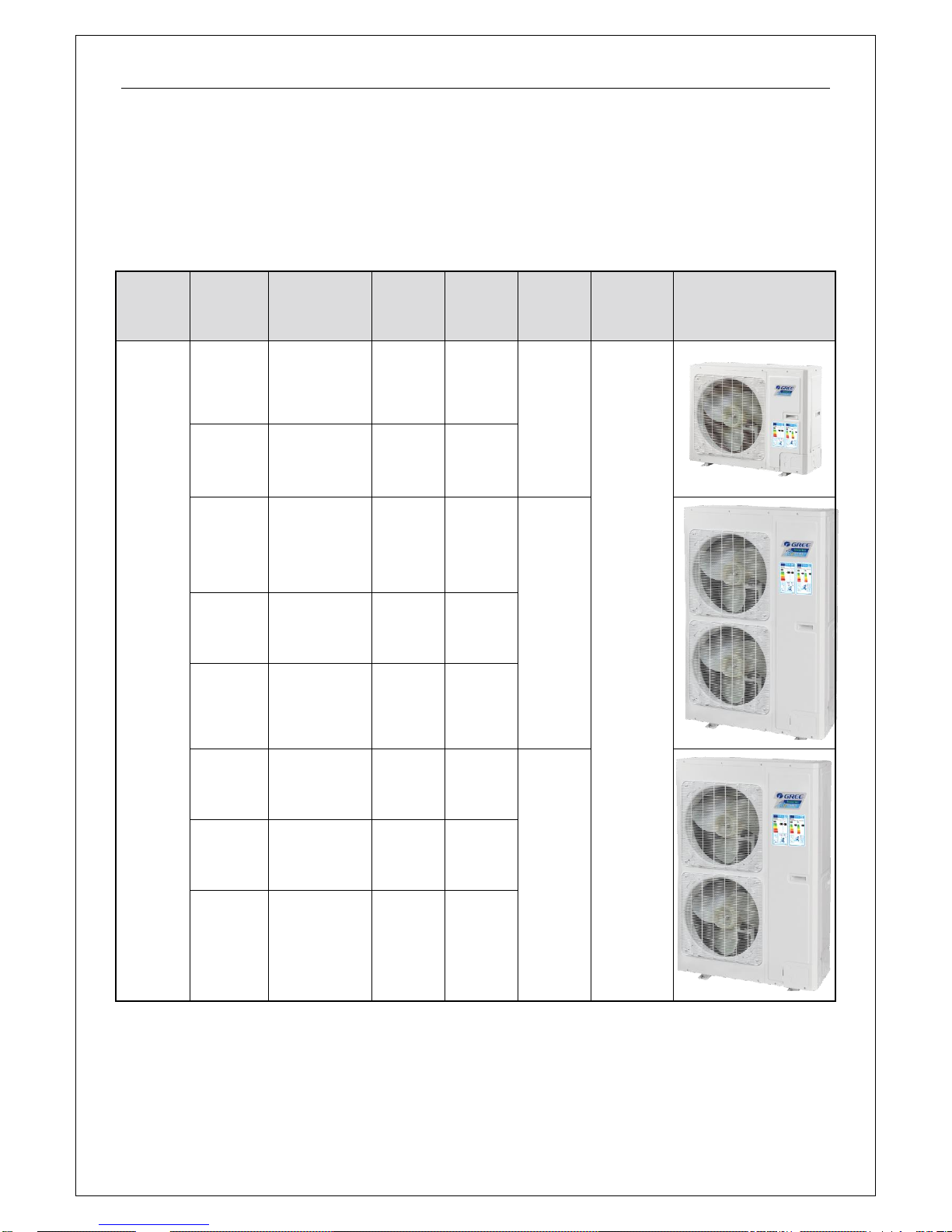
1.1.1 Main Unit
Series
Model
Product Code
Cooling
Capacity
(kW)
Heating
Capacity
(kW)
Power
Supply
Refrigerant
Appearance
VERSATI
Ⅱ
GRS-CQ8
.0Pd/NaE-
K
ER01001300
7.8
8
220-240V
,~,50Hz
R410A
GRS-CQ1
0Pd/NaE-
K
ER01001290
8.2
10
GRS-CQ1
2Pd/NaE-
K
ER01001280
12.5
12
220-240V
,~,50Hz
GRS-CQ1
4Pd/NaE-
K
ER01001270
13.5
14
GRS-CQ1
6Pd/NaE-
K
ER01001260
14.5
15.5
GRS-CQ1
2Pd/NaE-
M
ER01001250
13.5
12
380-415V,3
N~,50Hz
GRS-CQ1
4Pd/NaE-
M
ER01001240
14.5
14
GRS-CQ1
6Pd/NaE-
M
ER01001230
15
15.5
Product
2
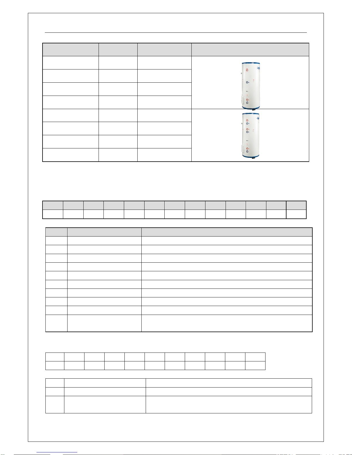
1.1.2 Water Tank
Model
Product Code
Nominal Cubage(L)
Appearance
SXVD200LCJ/A-K
ER20000160
200
SXVD200LCJ/A-M
ER20000240
200
SXVD300LCJ/A-K
ER20000180
300
SXVD300LCJ/A-M
ER20000250
300
SXVD200LCJ2/A-K
ER20000170
200
SXVD200LCJ2/A-M
ER20000260
200
SXVD300LCJ2/A-K
ER20000190
300
SXVD300LCJ2/A-M
ER20000270
300
1.2 Nomenclature
1.2.1 Main Unit
G
RS - C Q 16
Pd / Na E - M (O) 1 2 3 4 5 6 7 8 9
10 NO.
Description
Options
1
GREE
G-GREE Air to water heat pump
2
Heat Pump Water Heater
RS 3 Heating Mode
S= Static; C=Circulating
4
Function
Q=Multi-function; Omit=Single-function
5
Nominal Heating Capacity
6.0=6.0kW; 8.0=8.0kW;10=10kW; 12=12kW; 14=14kW; 16=16kW
6
Compressor Style
Pd=DC Inverter; Omit=On/Off
7
Refrigerant
Na=R410A
8
Design Serial Number
B,C,D...... 9 Power Supply
K=220-240V,~,50Hz; M=380-415V,3N~,50Hz;H=380V,3N~,60Hz
10
Indoor and Outdoor Unit
Code
I=Indoor unit; O=Outdoor unit
1.2.2 Water Tank
SX V D
200 L C
J2 / A - K 1 2 3 4 5 6 7 8
9 NO.
Description
Options
1
Symbol of Heat Pump Water Tank
SX
2
Tank Type
Default-Common heat pump water tank;
V-Heat pump water tank for multi VRF system
Product
3
3
Function Code
Default-No electric heating function;
D-Electric heating function available
4
Nominal Water Tank Volume
200=200L,300=300L
5
Structure Type
B-Wall mounted type; L-Floor standing type
6
Bearing
Default-Non-bearing water tank;
C-Bearing water tank
7
Type of Heat Exchange Tube
Default-No heat exchanger;
J-Inner coil static heating(J-Single coil; J2-Double coils);
JW-Outer coil static heating
8
Serial Number
A,B,C……
9
Power Supply
K=220-240V,~,50Hz; M=380-415V,3N~,50Hz; H=380V,3N~,60Hz
1.3 Product Features
1.3.1 General
GREE air to water heat pump is a completely flexible, energy efficient home heating system that
extracts the heat from the outside air, raises this heat to a higher temperature and then distribute
swarmth around the home using under-floor heating, radiators or fan convector heat emitters.
1.3.2 Features
Wide Operation Range
Heating: -22~35°C; Cooling: 10~48°C; Water Heating: -22~45°C.
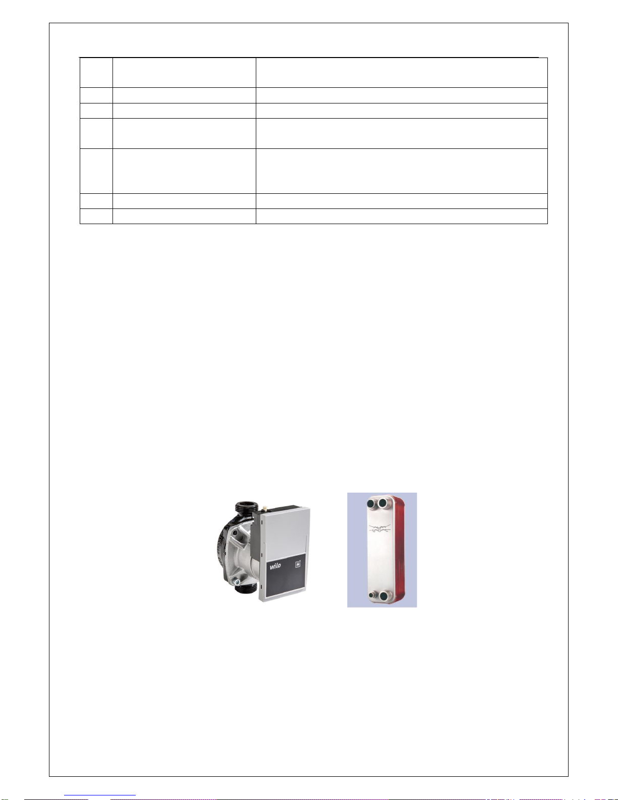
High-efficiency Component(Inverter pump, Inverter fan, Plate heat exchanger)
1. The A-class high-efficiency inverter water pump which complies with the European Erp directive,
can control the running frequency based on the actual load. Therefore, it can enhance the operation
effcieicy and control the water temperature more accurately.
2. The DC inverter fan can control the air volume accuratately and make the system run more stably
and save more energy.
3. The high-efficiency plate heat exchanger will improve the unit’s performance largely at a low price.
All-in-one Design
1. The unit can integrate with terminal units, like the radiator, floor heating device, FCU, water
heating device, solar kit, gas furnace and swimming pool etc. Versatile functions can meet various kinds
of demands from different users and enhance applicability of this product.
2. The all-in-one structure design can save more installation cost, reduce risks of refrigerant leak,
and improve safety and reliability of the system.
Brand-new Controller
1. White appearance, exquisite design, and the wall-mounted design will facilitate installation.
Product
4
2. The dot-matrix display can show in both English and Chinese to show information in a more direct
and convenient way.
3. The six-lattice display pattern will accommodate more information.
4. The 12V JACK interface can supply power to the control separately and lengthen the
communication distance.
5. The remote monitoring interface can monitor the unit through the Mobus interface and be
integrated into the BMS system.
Smart Control, Powerful Function
1. The running mode can be switched freely. Furthermore, based on different demands, the holiday
mode, environment-dependent mode, quite timer, temperature timer and floor commissioning can
activated.
2. Multiple protections can make this product much safer. The added electric heater will prevent the
plate heat exchanger from being frostbitten owing to too low water temperature and resultantly extend
the service life of the product and enhance its safety and reliability.
3. The newly developed smart defrosting control program, “do defrost when necessary; do not
defrost when unnecessary; defrost more when it frosts heavily; defrost less when it frosts lightly”, can
bring more comfortability, avoid inadequacy of heat supply and ensure sustainable heat supply for the
users.
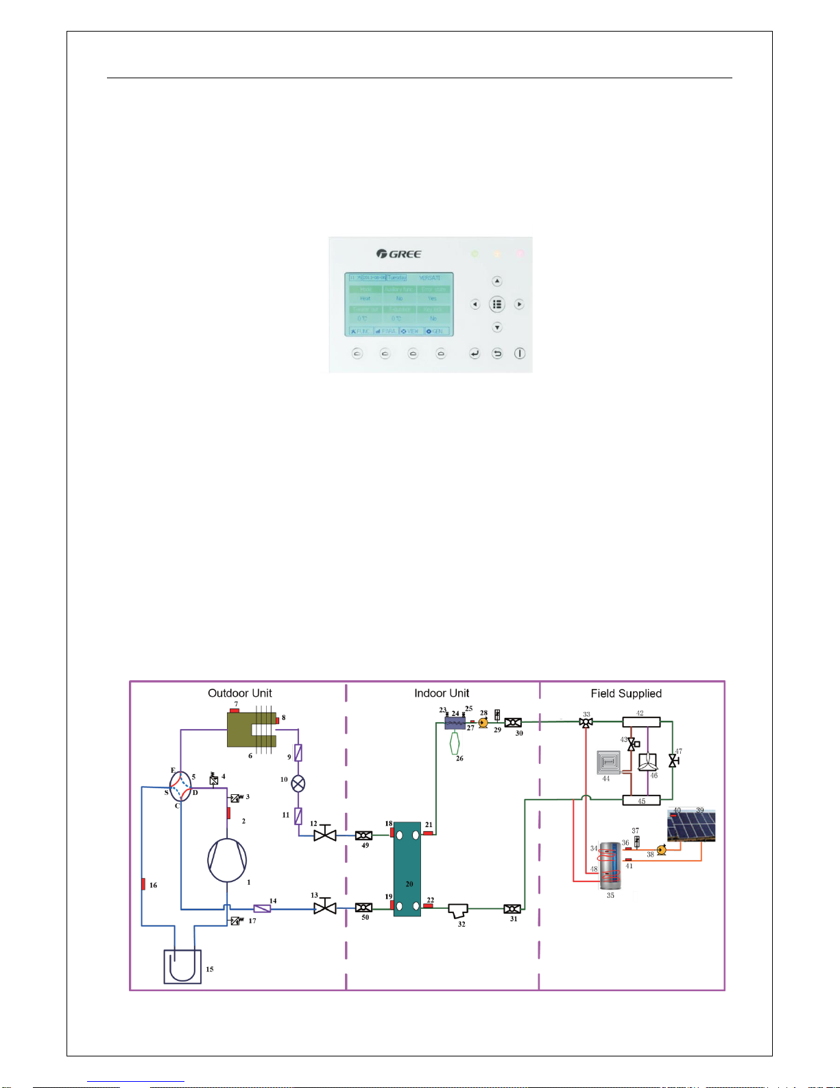
1.4 Operating Principle
1.4.1 Schematic Diagram

Product
5
No.
Name
No.
Name
No.
Name
1
Compressor
18
Liquid Temperature
Sensor of the PHE
35
Water Tank
2
Discharge Temperature
Sensor
19
Gas Temperature Sensor
of the PHE
36
Leaving Water Temperature
Sensor of the Solar System
3
High Pressure Switch
20
Plate-type Exchanger
37
Flow Switch for the Solar
System
4
Pressure Sensor
21
Leaving Water
Temperature
of the PHE
38
Water Pump for the Solar
System
5
4-way Valve
22
Entering Water
Temperature
of the PHE
39
Solar Panel
6
Finned Exchanger
23
Automatic Exhaust Valve
40
Solar Panel Temperature Sensor
7
Environment Temperature
Sensor
24
Electric Heater
41
Entering Water Temperature
for the Solar System
8
Defrosting Temperature
Sensor
25
Safety Valve
42
Water Knockout Vessel
9
Filter
26
Expansion Tank
43
Electric 2-way Valve 1
10
Electrostatic Expansion
Valve
27
Leaving Water
Temperature
of the Electric Heate
44
Floor Radiator
11
Filter
28
Water Pump
45
Water Collector
12
Liquid Valve
29
Flow Switch
46
FCU
13
Gas Valve
30
Leaving Water Pipe
Connector
47
Pressure Differential Bypass
Valve
14
Filter
31
Entering Water Pipe
Connector
48
Water Tank Temperature
Sensor 2
15
Vapor-liquid Separator
32
Water Filter
49
Liquid Valve Connector
16
Suction Temperature Sensor
33
Electric 3-way Valve 2
50
Gas Valve Connector
17
Pressure Sensor
34
Water Tank Temperature
Sensor 1
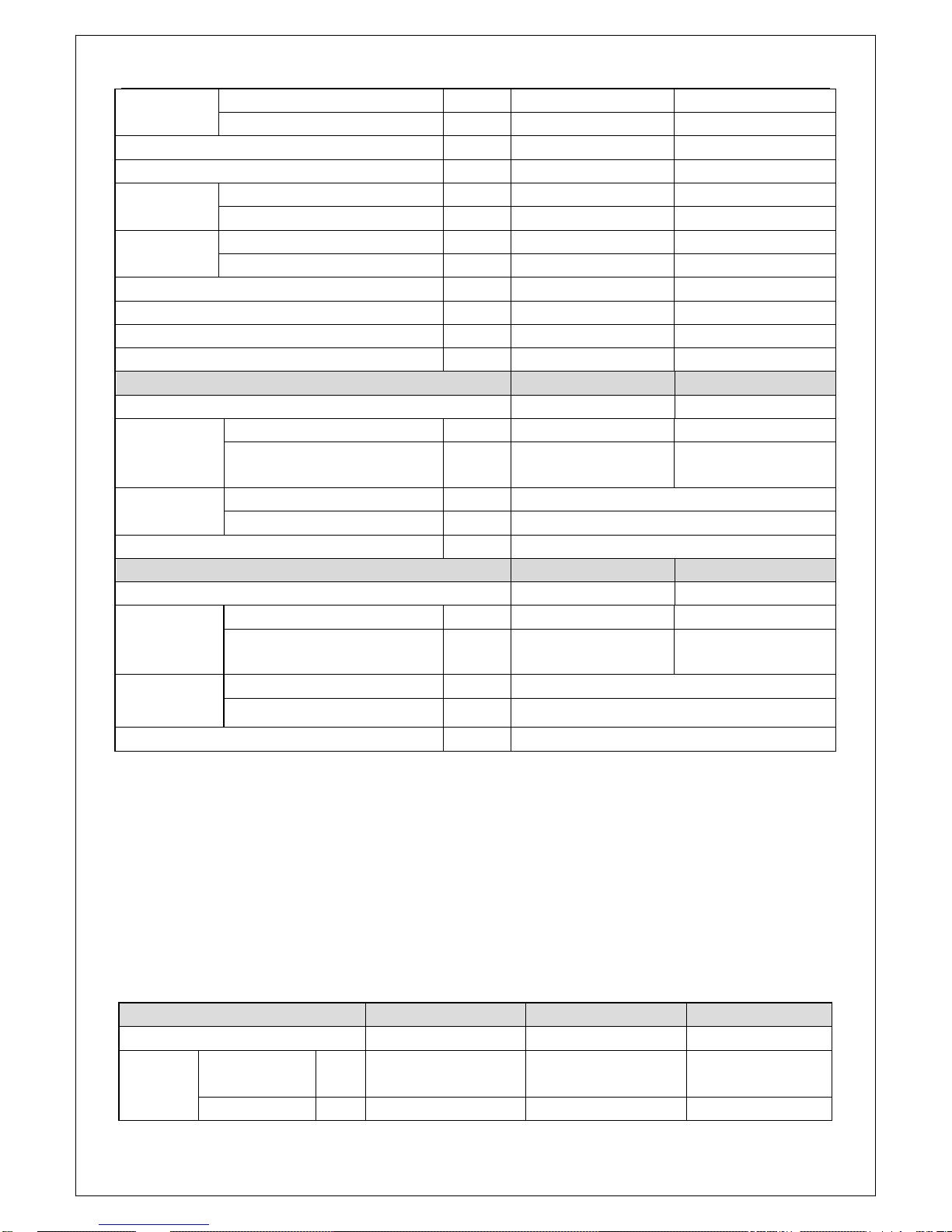
1.5 Technical Data
1.5.1 Parameter List
Model
GRS-CQ8.0Pd/NaE-K
GRS-CQ10Pd/NaE-K
Product Code
ER01001300
ER01001290
Capacity*1
Cooling(floor cooling)
kW
7.8
8.2
Heating(floor heating)
kW 8 10
Product
6
Power Input*1
Cooling(floor cooling)
kW
1.95
2.1
Heating(floor heating)
kW
1.778
2.273
EER*1(floor cooling)
W/W
3.9
4.0
COP*1(floor heating)
W/W
4.4
4.5
Capacity*2
Cooling(for Fan coil)
kW
6.3
7.2
Heating(Fan coil or Radiator)
kW
7.6
9.5
Power Input*2
Cooling(for Fan coil)
kW
2.33
2.77
Heating(Fan coil or Radiator)
kW
2.24
2.88
EER*2(for Fan coil)
W/W
2.6
2.7
COP*2(Fan coil or Radiator)
W/W
3.3
3.4
Refrigerant charge volume
kg
2.3
2.3
Sanitary water Temperature
℃
40~80
40~80
Outdoor Unit Model
GRS-CQ8.0Pd/NaE-K(O)
GRS-CQ10Pd/NaE-K(O)
Outdoor Unit Product Code
ER010W1300
ER010W1290
Sound
Pressure
Level
cooling
dB(A)
54
54
heating
dB(A)
56
56
Dimensions
(W×D×H)
Outline
mm
980×427×788
Packaged
mm
1097×862×477
Net weight/Gross weight
kg
80/85
Indoor Unit Model
GRS-CQ8.0Pd/NaE-K(I)
GRS-CQ10Pd/NaE-K(I)
Indoor Unit Product Code
ER010N1300
ER010N1290
Sound
Pressure
Level
cooling
dB(A)
31
31
heating
dB(A)
31
31
Dimensions
(W×D×H)
Outline
mm
981×324×500
Packaged
mm
1043×395×608
Net weight/Gross weight
kg
56/65
Notes
“*1” indicates the capacity and power input are tested based on the conditions below:
① Cooling
Indoor Water Temperature: 23°C/18°C; Outdoor Temperature: 35°CDB/24°CWB
② Heating
Indoor Water Temperature: 30°C/35°C; Outdoor Temperature: 7°CDB/6°CWB
“*2” indicates the capacity and power input are tested based on the conditions below:
① Cooling
Indoor Water Temperature: 12°C/7°C; Outdoor Temperature: 35°CDB/24°CWB
② Heating
Indoor Water Temperature: 40°C/45°C; Outdoor Temperature: 7°CDB/6°CWB
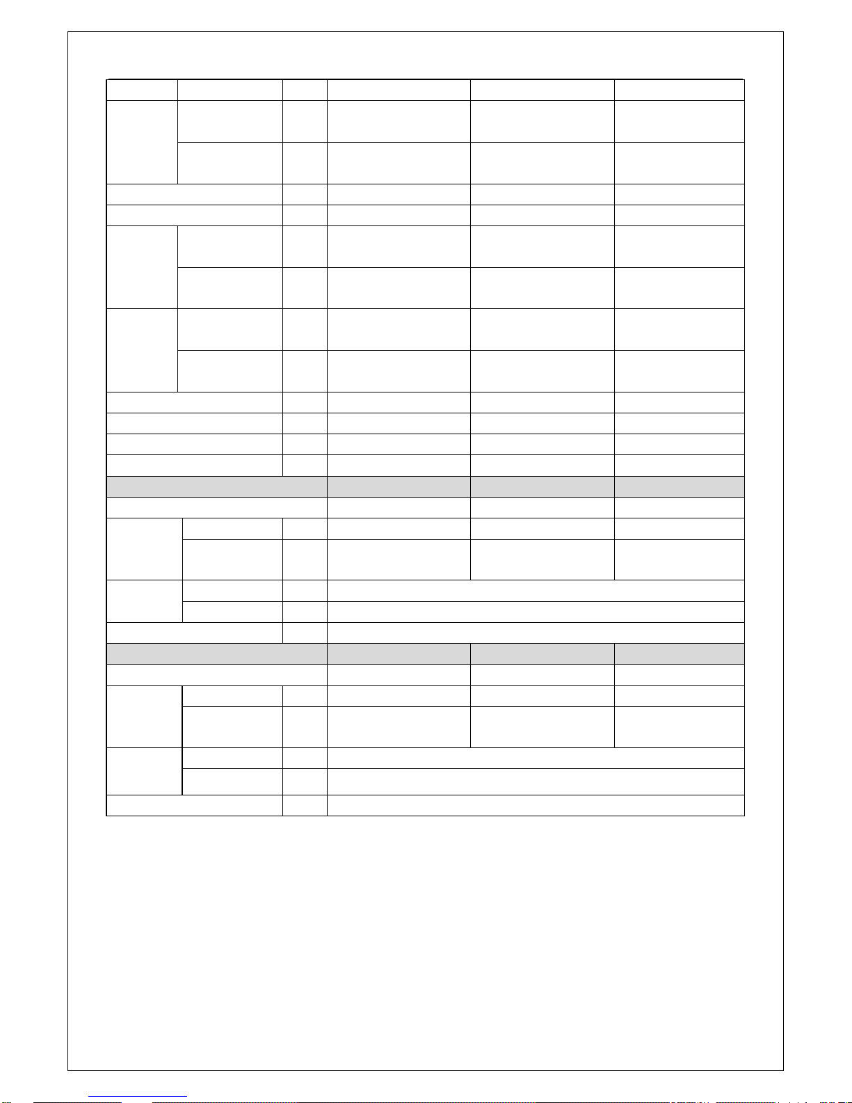
Model
GRS-CQ12Pd/NaE-K
GRS-CQ14Pd/NaE-K
GRS-CQ16Pd/NaE-K
Product Code
ER01001280
ER01001270
ER01001260
Capacity*1
Cooling(floor
cooling)
kW
12.5
13.5
14.5
Heating(floor
kW
12
14
15.5
Product
7
heating)
Power
Input*1
Cooling(floor
cooling)
kW
3
3.4
3.8
Heating(floor
heating)
kW
2.8
3.3
3.75
EER*1(floor cooling)
W/W
4.2 4 3.8
COP*1(floor heating)
W/W
4.3
4.2
4.1
Capacity*2
Cooling(for Fan
coil)
kW
8.5
9
9.5
Heating(Fan coil
or Radiator)
kW
11.5
12.5
14.5
Power
Input*2
Cooling(for Fan
coil)
kW
2.7
3
3.3
Heating(Fan coil
or Radiator)
kW
3.4
3.8
4.5
EER*2(for Fan coil)
W/W
3.1 3 2.9
COP*2(Fan coil or Radiator)
W/W
3.35
3.3
3.2
Refrigerant charge volume
Kg
3.6
3.6
3.6
Sanitary water Temperature
℃
40~80
40~80
40~80
Outdoor Unit Model
GRS-CQ12Pd/NaE-K(O)
GRS-CQ14Pd/NaE-K(O)
GRS-CQ16Pd/NaE-K(O)
Outdoor Unit Product Code
ER010W1280
ER010W1270
ER010W1260
Sound
Pressure
Level
cooling
dB(A)
56
56
56
heating
dB(A)
58
58
58
Dimensions
(W×D×H)
Outline
mm
900×412×1345
Packaged
mm
998×458×1515
Net weight/Gross weight
kg
107/117
Indoor Unit Model
GRS-CQ12Pd/NaE-K(I)
GRS-CQ14Pd/NaE- K(I)
GRS-CQ16Pd/NaE- K(I)
Indoor Unit Product Code
ER010N1280
ER010N1270
ER010N1260
Sound
Pressure
Level
cooling
dB(A)
31
31
31
heating
dB(A)
31
31
31
Dimensions
(W×D×H)
Outline
mm
981×324×500
Packaged
mm
1043×395×608
Net weight/Gross weight
kg
57/66
Notes
“*1” indicates the capacity and power input are tested based on the conditions below:
① Cooling
Indoor Water Temperature: 23°C/18°C; Outdoor Temperature: 35°CDB/24°CWB
② Heating
Indoor Water Temperature: 30°C/35°C; Outdoor Temperature: 7°CDB/6°CWB
“*2” indicates the capacity and power input are tested based on the conditions below:
① Cooling
Indoor Water Temperature: 12°C/7°C; Outdoor Temperature: 35°CDB/24°CWB
Product
8
② Heating
Indoor Water Temperature: 40°C/45°C; Outdoor Temperature: 7°CDB/6°CWB
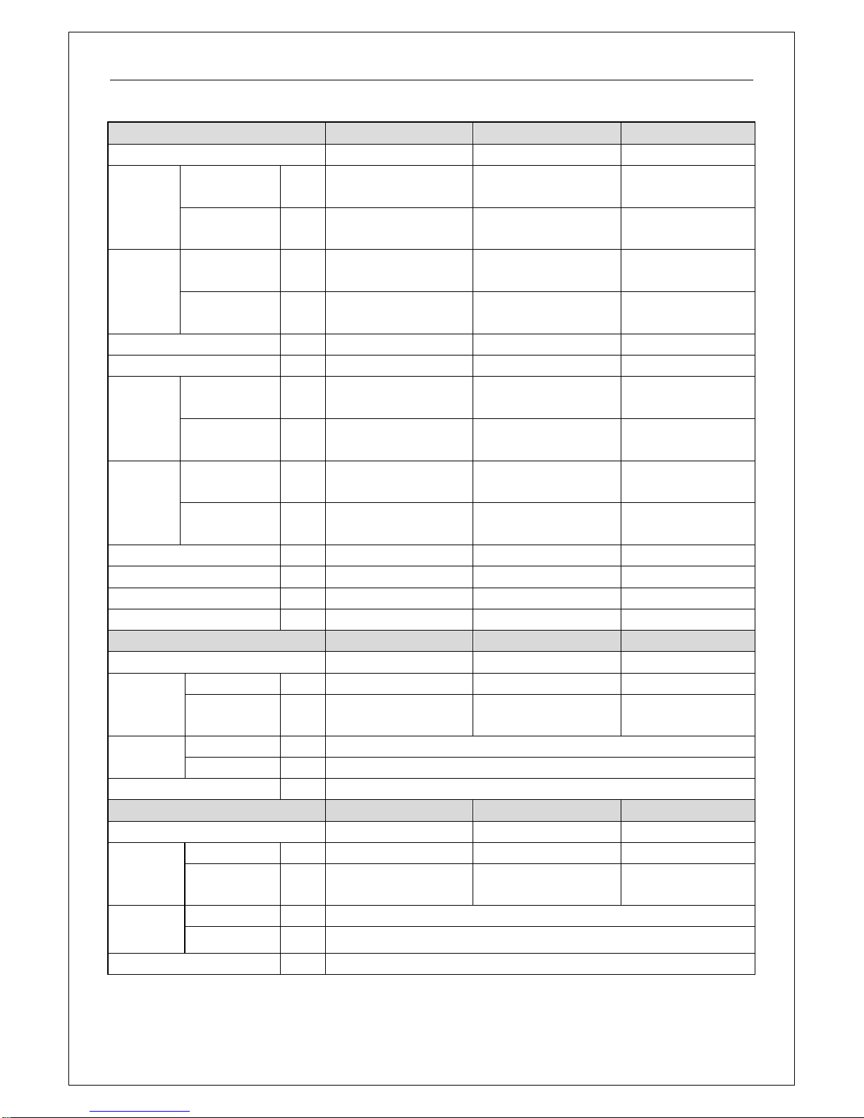
Model
GRS-CQ12Pd/NaE-M
GRS-CQ14Pd/NaE-M
GRS-CQ16Pd/NaE-M
Product Code
ER01001250
ER01001240
ER01001230
Capacity*1
Cooling(floor
cooling)
kW
13.5
14.5
15
Heating(floor
heating)
kW
12
14
15.5
Power
Input*1
Cooling(floor
cooling)
kW
3.55
3.95
4.2
Heating(floor
heating)
kW
2.8
3.35
3.85
EER*1(floor cooling)
W/W
3.8
3.7
3.6
COP*1(floor heating)
W/W
4.3
4.2
4.05
Capacity*2
Cooling(for Fan
coil)
kW
10
10.5
11
Heating(Fan
coil or Radiator)
kW
12
13.5
14
Power
Input*2
Cooling(for Fan
coil)
kW
3.35
3.6
3.8
Heating(Fan
coil or Radiator)
kW
3.55
4.05
4.25
EER*2(for Fan coil)
W/W 3 2.95
2.9
COP*2(Fan coil or Radiator)
W/W
3.4
3.35
3.3
Refrigerant charge volume
Kg
3.6
3.6
3.6
Sanitary water Temperature
℃
40~80
40~80
40~80
Outdoor Unit Model
GRS-CQ12Pd/NaE-M(O)
GRS-CQ14Pd/NaE-M(O)
GRS-CQ16Pd/NaE-M(O)
Outdoor Unit Product Code
ER01001250
ER01001240
ER01001230
Sound
Pressure
Level
cooling
dB(A)
55
55
55
heating
dB(A)
57
57
57
Dimensions
(W×D×H)
Outline
mm
900×1345×412
Packaged
mm
998×1515×458
Net weight/Gross weight
kg
114/124
Indoor Unit Model
GRS-CQ12Pd/NaE-M(I)
GRS-CQ14Pd/NaE- M(I)
GRS-CQ16Pd/NaE- M(I)
Indoor Unit Product Code
ER01001250
ER01001240
ER01001230
Sound
Pressure
Level
cooling
dB(A)
31
31
31
heating
dB(A)
31
31
31
Dimensions
(W×D×H)
Outline
mm
981×324×500
Packaged
mm
1043×395×608
Net weight/Gross weight
kg
58/67
Notes
“*1” indicates the capacity and power input are tested based on the conditions below:
Product
9
① Cooling
Indoor Water Temperature: 23°C/18°C; Outdoor Temperature: 35°CDB/24°CWB
② Heating
Indoor Water Temperature: 30°C/35°C; Outdoor Temperature: 7°CDB/6°CWB
“*2” indicates the capacity and power input are tested based on the conditions below:
① Cooling
Indoor Water Temperature: 12°C/7°C; Outdoor Temperature: 35°CDB/24°CWB
② Heating
Indoor Water Temperature: 40°C/45°C; Outdoor Temperature: 7°CDB/6°CWB
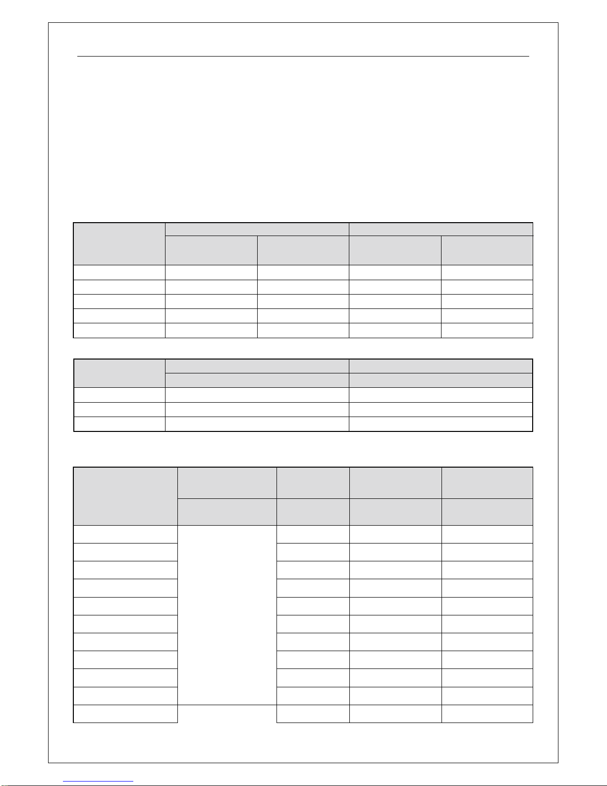
1.5.2 Nominal Working Conditions
Item
Water Side
Air side
Entering Water Temp
(°C)
Leaving Water
Temperature (°C)
Dry Bulb
Temperature (°C)
Wet Bulb
Temperature (°C)
Floor Heating
30
35 7 6
FCU Heating
40
45 7 6
Floor Cooling
23
18
35
—
FCU Cooling
12 7 35
—
Water Heating
10
50 7 6
1.5.3 Operation Range
Item
Water Side
Air side
Leaving Water Temperature (°C)
Environment Dry Bulb Temperature (°C)
Cooling
7~25
10~48
Heating
25~55
-22~35
Water Heating
40~80 (Water Tank Temperature)
-22~45
Note: when operating conditions are out of the range listed above, please contact GREE.
1.5.4 Electric Data
Model
Power Supply
Leakage Switch
Minimum Sectional
Area of Earth Wire
Minimum Sectional
Area of Power
V,Ph,Hz
(A)
(mm2)
(mm2)
GRS-CQ8.0Pd/NaE-K(O
220-240V,~,50Hz
25
3.3
2×3.3
GRS-CQ10Pd/NaE-K(O)
25
3.3
2×3.3
GRS-CQ8.0Pd/NaE-K(I)
50
13.3
2×13.3
GRS-CQ10Pd/NaE-K(I)
50
13.3
2×13.3
GRS-CQ12Pd/NaE-K(O)
35
8.4
2×8.4
GRS-CQ14Pd/NaE-K(O)
35
8.4
2×8.4
GRS-CQ16Pd/NaE-K(O)
35
8.4
2×8.4
GRS-CQ12Pd/NaE-K(I)
50
13.3
2×13.3
GRS-CQ14Pd/NaE-K(I)
50
13.3
2×13.3
GRS-CQ16Pd/NaE-K(I)
50
13.3
2×13.3
GRS-CQ12Pd/NaE-M(O)
380-415V,3N~,50Hz
25
3.3
4×3.3
Product
10
GRS-CQ14Pd/NaE-M(O)
25
3.3
4×3.3
GRS-CQ16Pd/NaE-M(O)
25
3.3
4×3.3
GRS-CQ12Pd/NaE-M(I)
20
3.3
4×3.3
GRS-CQ14Pd/NaE-M(I)
20
3.3
4×3.3
GRS-CQ16Pd/NaE-M(I)
20
3.3
4×3.3
Notes
① L
eakage Switch is necessary for additional installation. If circuit breakers with leakage
protection are in use, action response time must be less than 0.1 second, leakage circuit must
be 30mA.
②
The above selected power cable diameters are determined based on assumption of distance
from the distribution cabinet to the unit less than 75m. If cables are laid out in a distance of 75m
to 150m, diameter of power cable must be increased to a further grade.
③
The power supply must be of rated voltage of the unit and special electrical line for
air-conditioning.
④
All electrical installation shall be carried out by professional technicians in accordance with the
local laws and regulations.
⑤
Ensure safe grounding and the grounding wire shall be connected with the special grounding
equipment of the building and must be installed by professional technicians.
⑥
The specifications of the breaker and power cable listed in the table above are determined
based on the maximum power (maximum amps) of the unit.
⑦
The specifications of the power cable listed in the table above are applied to the
conduit-guarded multi-wire copper cable (like, YJV XLPE insulated power cable) used at 40°C
and resistible to 90°C(see IEC 60364-5-52). If the working condition changes, they should be
modified according to the related national standard.
⑧
The specifications of the breaker listed in the table above are applied to the breaker with the
working temperature at 40°C. If the working condition changes, they should be modified
according to the related national standard.
1.5.5 Capacity Correction
Cooling Capacity Correction
GRS-CQ8.0Pd/NaE-K,GRS-CQ10Pd/NaE-K,GRS-CQ12Pd/NaE-K,GRS-CQ14Pd/NaE-K,
GRS-CQ16Pd/NaE-K,GRS-CQ12Pd/NaE-M,GRS-CQ14Pd/NaE-M,GRS-CQ16Pd/NaE-M.
Performance correction
Leaving Chilled Water ℃(℉)
Ambient Temperature ℃(℉)
25(77)
30(86)
35(95)
40(104)
45(113)
5(41.0)
0.995
0.955
0.905
0.855
0.805
6(42.8)
1.045
1.005
0.955
0.905
0.855
7(44.6)
1.090
1.050
1.000
0.950
0.900
8(46.4)
1.145
1.102
1.052
1.000
0.950
9(48.2)
1.190
1.150
1.100
1.050
1.002
10(50.0)
1.245
1.200
1.150
1.100
1.050
11(51.8)
1.290
1.250
1.202
1.152
1.102
12(53.6)
1.340
1.300
1.252
1.200
1.152
13(55.4)
1.390
1.350
1.302
1.252
1.202

Product
11
14(57.2)
1.442
1.402
1.350
1.302
1.252
15(59.0)
1.490
1.450
1.400
1.350
1.302
18(64.4)
1.539
1.502
1.451
1.402
1.350
Computer of actual cooling capacity: actual cooling capacity = nominal cooling capacity x cooling
capacity correction coefficient.
Heating Capacity Correction
GRS-CQ8.0Pd/NaE-K,GRS-CQ10Pd/NaE-K,GRS-CQ12Pd/NaE-K,GRS-CQ14Pd/NaE-K,
GRS-CQ16Pd/NaE-K,GRS-CQ12Pd/NaE-M,GRS-CQ14Pd/NaE-M,GRS-CQ16Pd/NaE-M.
Performance Correction
Outflow
Heated
Water ℃(℉)
Ambient Temperature ℃(℉)
-15(5)
-10(14)
-5(23)
0(32)
5(41.0)
10(50)
15(59.0)
20(68.0)
25(77.4)
30(86)
0.81
0.91
1.00
1.10
1.18
1.26
1.35
1.41
1.45
35(95)
0.74
0.84
0.93
1.03
1.11
1.19
1.28
1.36
1.41
40(104)
0.67
0.77
0.87
0.96
1.04
1.12
1.20
1.25
1.31
45(113)
0.60
0.70
0.80
0.89
0.97
1.05
1.13
1.19
1.25
50(122)
0.53
0.63
0.73
0.82
0.90
0.98
1.06
1.11
1.18
55(131)
0.46
0.56
0.66
0.74
0.83
0.90
0.98
1.05
1.10
Computer of actual heating capacity: actual heating capacity = nominal heating capacity x heating
capacity correction coefficient.
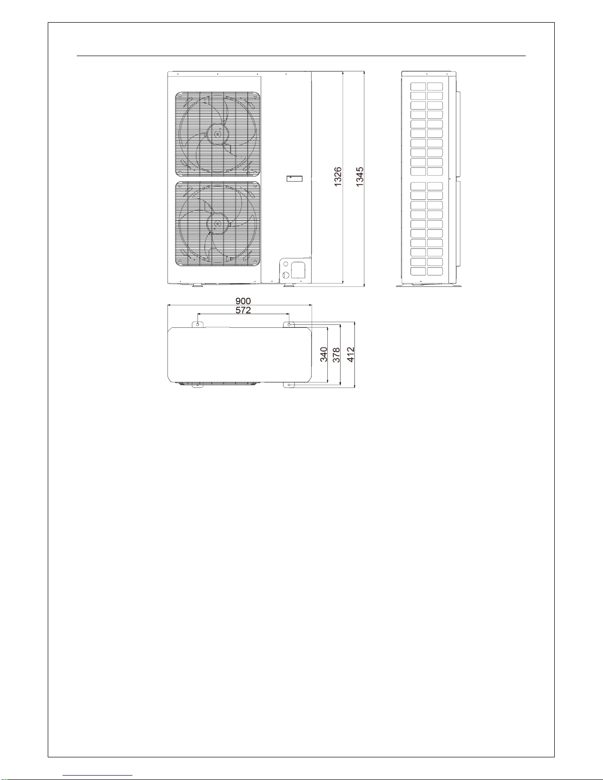
2 Outline Dimensions
2.1 Outline dimensions of outdoor unit
GRS-CQ8.0Pd/NaE-K(O), GRS-CQ10Pd/NaE-K(O)
Product
12
GRS-CQ12Pd/NaE-K(O), GRS-CQ14Pd/NaE-K(O) , GRS-CQ16Pd/NaE-K(O)
GRS-CQ12Pd/NaE-M(O), GRS-CQ14Pd/NaE-M(O) , GRS-CQ16Pd/NaE-M(O)
Product
13
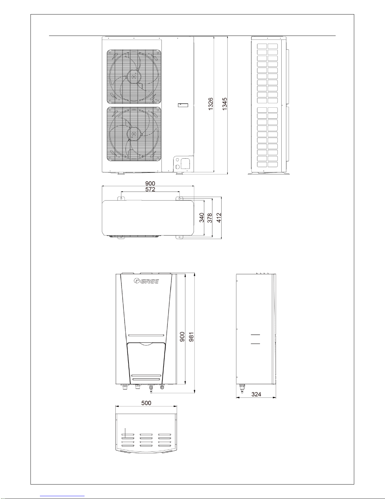
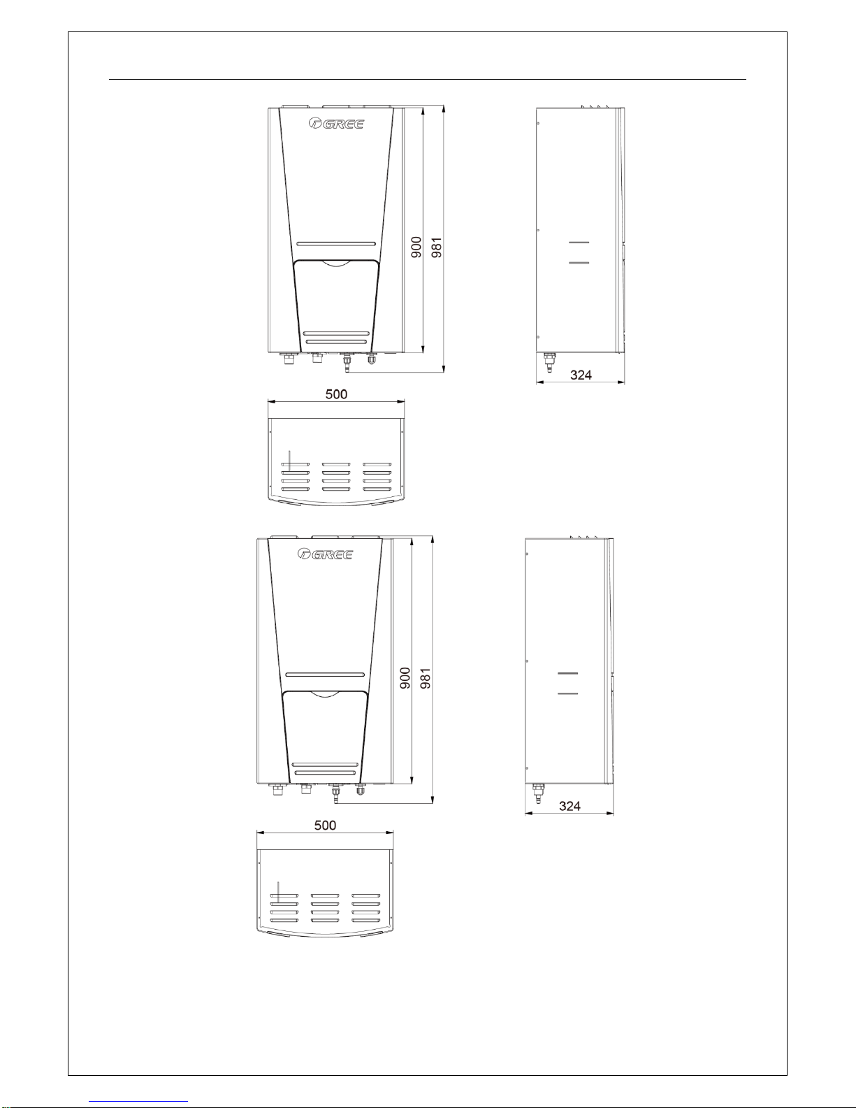
2.2 Outline dimensions of indoor unit
GRS-CQ8.0Pd/NaE-K(I), GRS-CQ10Pd/NaE-K(I)
Product
14
GRS-CQ12Pd/NaE-K(I), GRS-CQ14Pd/NaE-K(I) , GRS-CQ16Pd/NaE-K(I)
GRS-CQ12Pd/NaE-M(I), GRS-CQ14Pd/NaE-M(I) , GRS-CQ16Pd/NaE-M(I)
3 Explosive Views and Part Lists
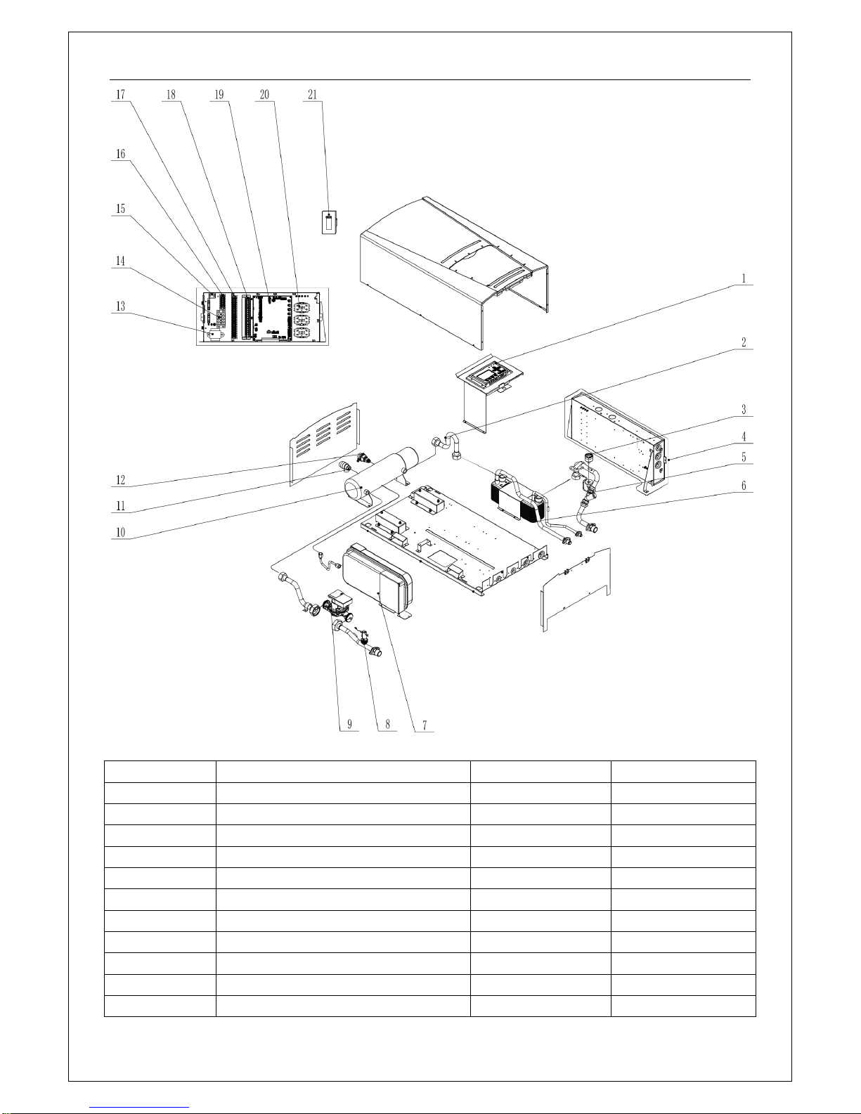
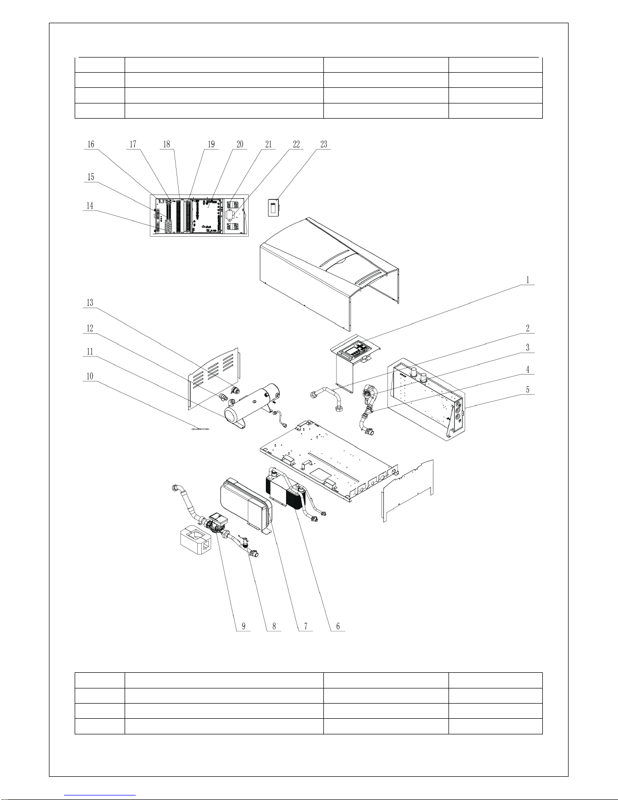
(1) GRS-CQ8.0Pd/NaE-K(I), GRS-CQ10Pd/NaE-K(I)
Product
15
Parts List of GRS-CQ8.0Pd/NaE-K(I) for ER010N1300, GRS-CQ10Pd/NaE-K(I)for ER010N1290.
No.
Name of part
Part Code
Quantity 1 Display Board
30292000047
1 2 Temp Sensor Sleeving
05212423
5 3 Water Pressure Gauge
49028009
1 4 Electric Box Assy
100002000198
1
5
Strainer
07412808
1 6 Plate-type Heat Exchanger
00902812
1 7 Expansion Drum
07422800004
1
8
Steam current Switch sub- Assy
45028062
1 9 Water Pump
812007000002
1
10
Electric Heater
32112800005
1
11
Relief Valve
07382814
1
Product
16
12
Auto Air Outlet Valve
07108208
1
13
Transformer
4311027001
1
14
Terminal Board
42011051
1
15
Thermostat
4504800201
1
16
Terminal Board
42011255
1
17
Terminal Board
42010249
1
18
Terminal Board
42011254
1
19
Main Board
30223000120
1
20
Bipolar AC Contactor
44010221
3
21
Receiver Board
30261014
1
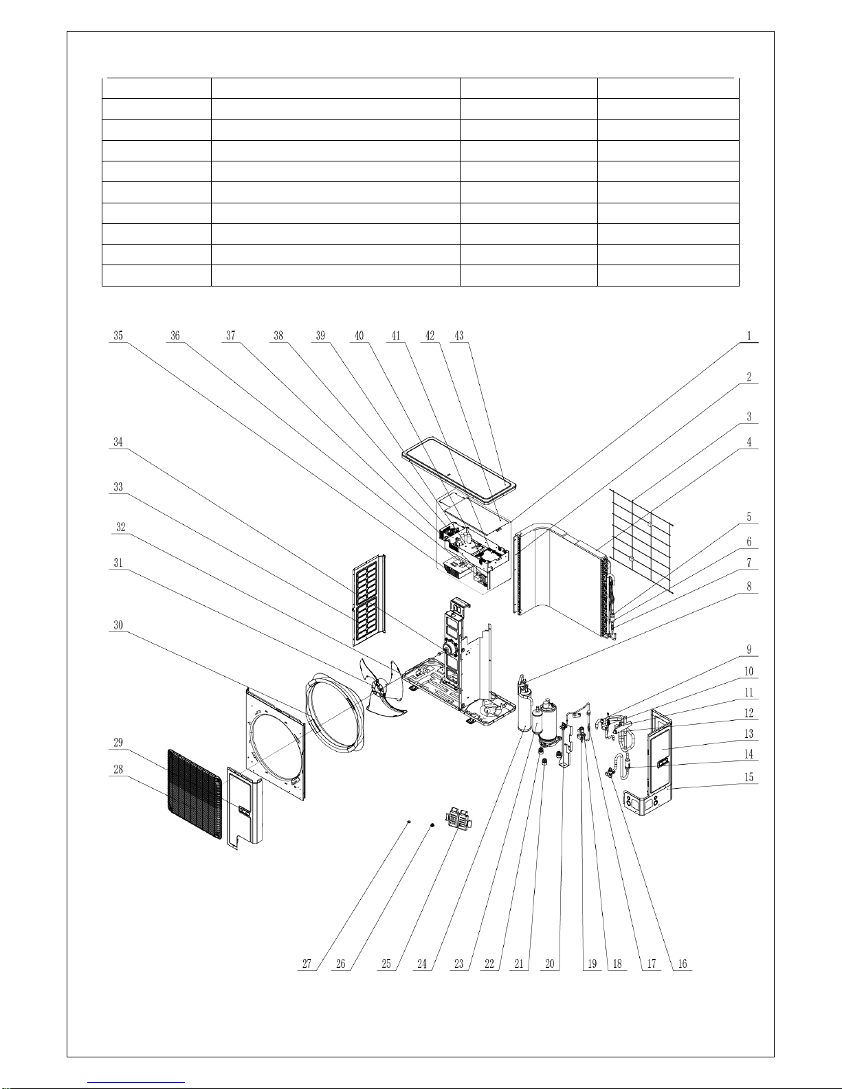
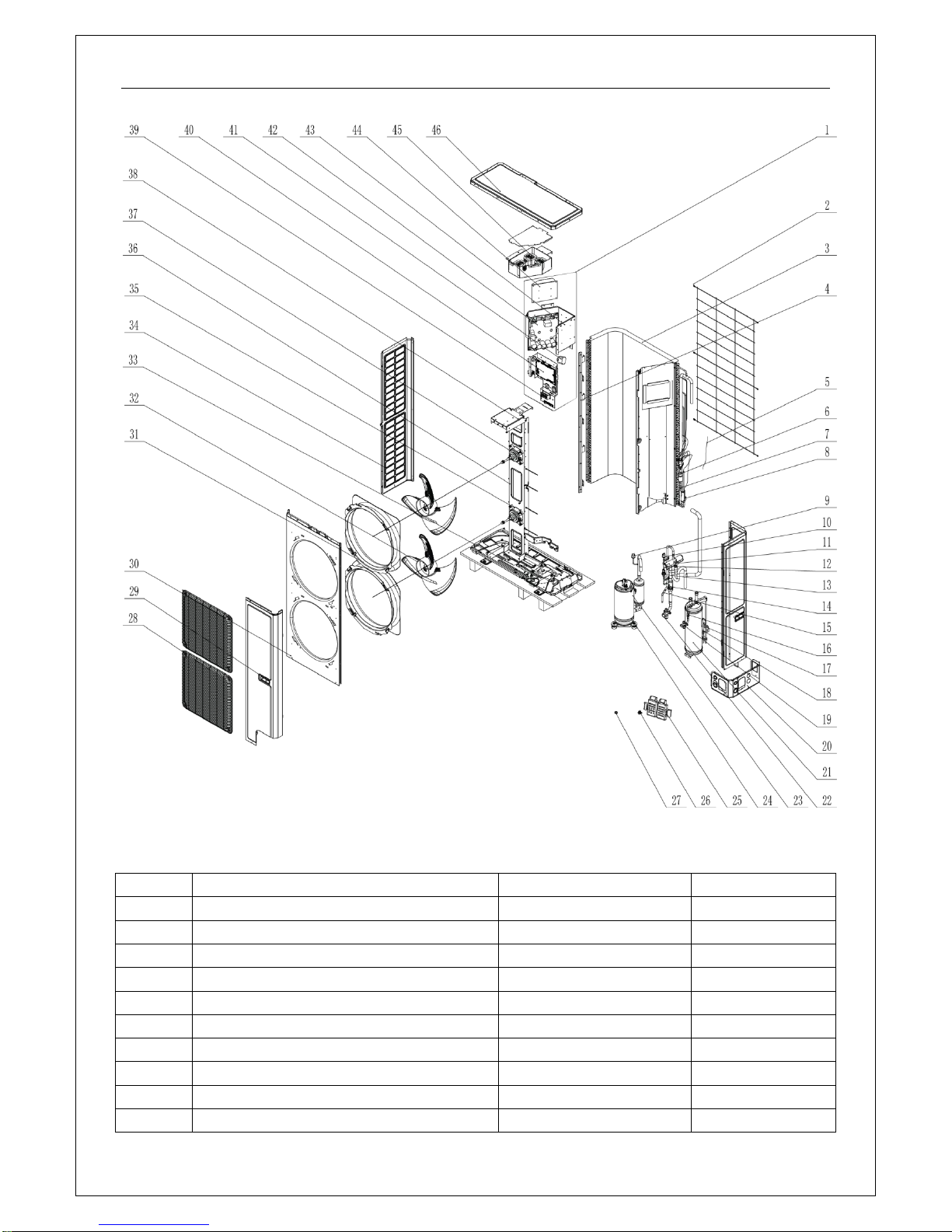
(2) GRS-CQ8.0Pd/NaE-K(O), GRS-CQ10Pd/NaE-K(O)
Parts List of GRS-CQ8.0Pd/NaE-K(I) for ER010N1300, GRS-CQ10Pd/NaE-K(I)for ER010N1290.

Product
17
No.
Name of part
Part Code
Quantity 1 Electric Box Assy
100002000095
1 2 Supporting Strip(Condenser)
01894100053
1
3
Rear Grill
01574100010
1 4 Condenser Assy
01122800082
1
5
Silencer
07245012
1 6 Temp Sensor Sleeving
05212423
2
7
Strainer
0721212101
1 8 Pressure Protect Switch
46020007
1 9 Pressure Protect Switch
46020006
1
10
Sensor (High Pressure)
322101032
1
11
Magnet Coil
4300040032
1
12
4-Way Valve
43040000002
1
13
Rear Side Plate
01314100045P
1
14
Strainer
07210032
1
15
Right Side Plate Sub-Assy
01314100109
1
16
Cut off Valve
07334100016
1
17
Strainer
0721200102
1
18
Electric Expand Valve Fitting
4300034402
1
19
Electronic Expansion Valve
07135176
1
20
Cut off Valve
07330000002
1
21
Compressor Gasket
76713066
3
22
Electrical Heater(Compressor)
7651873209
1
23
Compressor and Fittings
00205200003
1
24
Gas-liquid Separator
07422809
1
25
Sensor Support
26905202
1
26
Drainage Connecter
06123401
1
27
Drainage hole Cap
06813401
3
28
Front Grill
01572800003
1
29
Handle
26235253
2
30
Diversion Circle
10474100003
1
31
Axial Flow Fan
10335014
1
32
Electrical Heater
765100047
1
33
Left Side Plate
01314100043P
1
34
Brushless DC Motor
15702800004
1
35
Radiator
430034000006
1
36
Filter Board
30226000065
1
37
Terminal Board
42011242
1
38
Inductance
43120011
1
39
Main Board
30221000003
1
40
Filter Board
300020000004
1
41
Main Board
30227000038
1
42
Insulated Board (Cover of Electric Box)
20113003
1
43
Coping
01264100027P
1
Product
18
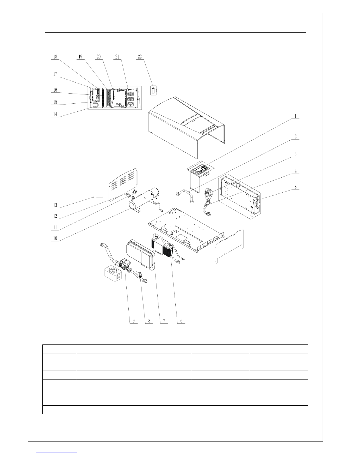
(3) GRS-CQ12Pd/NaE-K(I), GRS-CQ14Pd/NaE-K(I) , GRS-CQ16Pd/NaE-K(I).
Parts List of GRS-CQ12Pd/NaE-K(I) for ER010N1280, GRS-CQ14Pd/NaE-K(I) for ER010N1270,
GRS-CQ16Pd/NaE-K(I) for ER010N1260.
No.
Name of part
Part Code
Quantity
1
Display Board
30292000047
1 2 Temp Sensor Sleeving
05212423
5 3 Water Pressure Gauge
49028009
1
4
Strainer
07412808
1 5 Electric Box Assy
100002000198
1
6
Plate-type Heat Exchanger
00902800030
1 7 Expansion Drum
07422800004
1
Product
19
8
Steam current Switch sub- Assy
45028062
1
9
Water Pump
812007000002
1
10
Electric heater
32102802
1
11
Auto Air Outlet Valve
07108208
1
12
Relief Valve
07382814
1
13
Temperature Sensor
3900028316G
1
14
Transformer
4311027001
1
15
Terminal Board
42011051
1
16
Terminal Board
42010249
1
17
Thermostat
4504800201
1
18
Terminal Board
42011255
1
19
Terminal Board
42011254
1
20
Main Board
30223000120
1
21
Bipolar AC Contactor
44010221
3
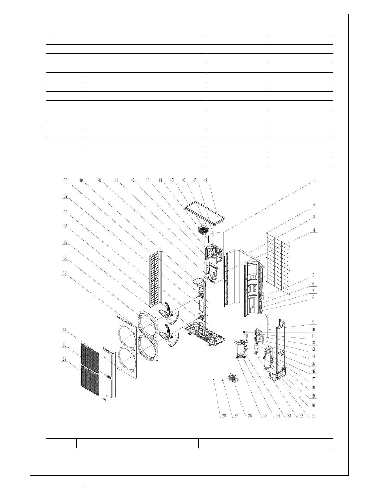
(4) GRS-CQ12Pd/NaE-K(O),GRS-CQ14Pd/NaE-K(O) ,GRS-CQ16Pd/NaE-K(O).
Parts List of GRS-CQ12Pd/NaE-K(O) for ER010W1280, GRS-CQ14Pd/NaE-K(O) for
ER010W1270, GRS-CQ16Pd/NaE-K(O) for ER010W1260.
No.
Name of part
Part Code
Quantity

Product
20
1
Electric Box Assy
01392800230
1
2
Rear Grill
01574100004
1 3 Condenser Sub-Assy
0115410000802
1 4 Supporting Strip(Condenser)
01894100026
1
5
Capillary tube
81020167
4
6
Silencer
07245012
1
7
Strainer
0721212101
1 8 Temp Sensor Sleeving
05212423
2 9 Pressure Protect Switch
46020006
1
10
Pressure Protect Switch
46020007
1
11
Magnet Coil
4300040032
1
12
4-Way Valve
43040000002
1
13
Sensor (High Pressure)
322101032
1
14
Strainer
07210037
1
15
Temp Sensor Sleeving
05210001
1
16
Strainer
0721200102
1
17
Electric Expand Valve Fitting
4304413221
1
18
Electronic Expansion Valve
43044100172
1
19
Cut off Valve
07330000002
1
20
Gas-liquid Separator
07424100014
1
21
Right Connection Board
01344100003P
1
22
Cut off Valve
07334100016
1
23
Compressor and Fittings
00204100001
1
24
Electrical Heater(Compressor)
7651521216
1
25
Compressor Gasket
76710247
3
26
Sensor Support
26905202
1
27
Drainage Connecter
06123401
1
28
Drainage hole Cap
06813401
3
29
Front Grill
01574100009
2
30
Handle
26235253
2
31
Cabinet
01514100002P
1
32
Diversion Circle
10474100001
2
33
Axial Flow Fan
10338731
2
34
Left Side Plate
01314100013P
1
35
Electrical Heater
765100047
1
36
Brushless DC Motor
15704100013
1
37
Motor Support
01805200243
1
38
Brushless DC Motor
1570410001301
1
39
Motor Support Sub-Assy
01805200244
1
40
Terminal Board
42011242
1
41
Main Board
30227000038
1
42
Filter Board
30226000065
1
43
Main Board
300027000068
1
44
Filter Board
300020000003
1
Product
21
45
Inductance
43120122
1
46
Inductance Assy
01394100050
1
47
Radiator
49018000013
1
48
Coping
01264100008P
1
(5) GRS-CQ12Pd/NaE-M(I),GRS-CQ14Pd/NaE-M(I) ,GRS-CQ16Pd/NaE-M(I).
Parts List of GRS-CQ12Pd/NaE-M(I) for ER010N1250, GRS-CQ14Pd/NaE-M(I) for ER010N1240,
GRS-CQ16Pd/NaE-M(I) for ER010N1230.
No.
Name of part
Part Code
Quantity 1 Display Board
30292000047
1
2
Temp Sensor Sleeving
05212423
5 3 Water Pressure Gauge
49028009
1

Product
22
4
Strainer
07412808
1 5 Electric Box Assy
100002000197
1 6 Plate-type Heat Exchanger
00902800030
1 7 Expansion Drum
07422800004
1 8 Steam current Switch sub- Assy
45028062
1
9
Water Pump
812007000002
1
10
Temperature Sensor
3900028316G
1
11
Electric Heater
32000004
1
12
Relief Valve
07382814
1
13
Auto Air Outlet Valve
07108208
1
14
Terminal Board
42011051
1
15
Terminal Board
42011135
1
16
Thermostat
4504800201
1
17
Terminal Board
42011103
1
18
Terminal Board
42010249
1
19
Terminal Board
42011254
1
20
Main Board
30223000120
1
21
AC Contactor
44010232
2
22
Transformer
4311027001
1
23
Receiver Board
30261014
1
1
Display Board
30292000047
1 2 Temp Sensor Sleeving
05212423
5 3 Water Pressure Gauge
49028009
1
4
Strainer
07412808
1 5 Electric Box Assy
100002000197
1 6 Plate-type Heat Exchanger
00902800030
1 7 Expansion Drum
07422800004
1 8 Steam current Switch sub- Assy
45028062
1
9
Water Pump
812007000002
1
10
Temperature Sensor
3900028316G
1
11
Electric Heater
32000004
1
12
Relief Valve
07382814
1
13
Auto Air Outlet Valve
07108208
1
14
Terminal Board
42011051
1
15
Terminal Board
42011135
1
16
Thermostat
4504800201
1
17
Terminal Board
42011103
1
18
Terminal Board
42010249
1
19
Terminal Board
42011254
1
20
Main Board
30223000120
1
21
AC Contactor
'44010232
2
22
Transformer
4311027001
1
23
Receiver Board
30261014
1
Product
23
(6) GRS-CQ12Pd/NaE-M(O),GRS-CQ14Pd/NaE-M(O) ,GRS-CQ16Pd/NaE-M(O).
Parts List of GRS-CQ12Pd/NaEM(O) for ER010W1250, GRS-CQ14Pd/NaE-M(O) for
ER010W1240, GRS-CQ16Pd/NaE-M(O) for ER010W1230.
No.
Name of part
Part Code
Quantity 1 Electric Box Assy
100002000085
1
2
Rear Grill
01574100004
1
3
Condenser Assy
000100000009
1
4
Supporting Strip(Condenser)
01894100026
1
5
Capillary tube
81020167
4
6
Silencer
07245012
1
7
Strainer
0721212101
1
8
Temp Sensor Sleeving
05212423
2
9
Pressure Protect Switch
46020007
1
10
Pressure Protect Switch
46020006
1
Product
24
11
Magnet Coil
4300040032
1
12
4-Way Valve
43040000002
1
13
Pressure Sensor(High Pressure)
322101038
1
14
Strainer
07210037
1
15
Temp Sensor Sleeving
05210001
1
16
Strainer
0721200102
1
17
Electric Expand Valve Fitting
4304413221
1
18
Electronic Expansion Valve
43044100172
1
19
Cut off Valve
07330000002
1
20
Right Connection Board
01344100003P
1
21
Gas-liquid Separator
07424100014
1
22
Cut off Valve
07334100016
1
23
Compressor and Fittings
00204100018
1
24
Electrical Heater(Compressor)
7651521216
1
25
Sensor Support
26905202
1
26
Drainage Connecter
06123401
1
27
Drainage hole Cap
06813401
3
28
Front Grill
01574100009
2
29
Handle
26235253
2
30
Cabinet
01514100002P
1
31
Diversion Circle
10474100001
2
32
Axial Flow Fan
10338731
2
33
Electrical Heater
765100047
1
34
Left Side Plate
01314100013P
1
35
Brushless DC Motor
15704100013
1
36
Motor Support
01805200243
1
37
Brushless DC Motor
1570410001301
1
38
Motor Support Sub-Assy
01805200244
1
39
Terminal Board
42011221
1
40
Main Board
30227000038
1
41
Inductance
43128000014
1
42
Main Board
30223000038
1
43
Filter Board
30223000044
1
44
Radiator
49018000087
1
45
Reactor
43130192
3
46
Coping
01264100008P
1
4 Supply Scope
S= Standard O= Optional F= Field Supplied
Name
Standard
Optional
Field Supplied
Owner's Manual for the Main Unit
√ / /
Owner’s Manual for the Control
√ / /
Product
25
2-way Valve
/ / √
3-way Valve
/
/
√
Remote Temperature Sensor
√ / /
Wired Controller
√ / /
Communication Cable
√ / /
Water Tank Temperature Sensor
√ / /
Expansion Bolt
√ / /
Solar System Water Pump
/
√ / Solar System Flow Switch
/
√
/
 Loading...