

Gree RVA-135R Owner's Manual, RVA-135RHP, RVA-150R, RVA-150RHP Operation & Installation

Change for Life
Recreational Vehicle
Owner's Manual
Operation & Installation
Thank you for choosing
Recreational Vehicle
manual carefully before operation and keep it for future reference.
Air Conditioner
Air Conditioner,Please read this owner’s
RVA-135R
RVA-135RHP
RVA-150R
RVA-150RHP
Models:
V.121210

CONTENTS
1. A FEW WORDS ABOUT YOUR NEW AIR CONDITIONING UNIT .................................1
5. OPERATION OF WIRELESS REMOTE CONTROL .......................................................5
6. CONTROL PANEL ...........................................................................................................9
...................................................................179. NORMAL MAINTENANCE PROCEDURES
......................................................................................................22. ELECTRIC DIAGRAM
7. INSTALLATION INSTRUCTION.....................................................................................10
.................................................................................................14
STEP 3-ELECTRICAL WIRING
................................................................................15
STEP 4-COMPLETING THE INSTALLATION
............................................................................13
STEP 2-INSTALLING THE CEILING ASSEMBLY
......10
STEP 1-SELECTING AN INSTALLATION LOCATION & INSTALLING THE ROOF TOP AIR CONDITIONER
.......................................................................................168. TROUBLESHOOTING GUIDE
.................................................................................................................33. PACKING LIST
............................................................................................................44. SPECIFICATIONS

A FEW WORDS ABOUT YOUR NEW
AIR CONDITIONING UNIT
ELECTRICAL
DATA
1.
All wiring must be complied with local and national electrical codes. All wiring
must be installed by qualified electricians. If you have
any questions about the
following instructions, contact a qualified
electrician.
2.
Check the available power supply and resolve any wiring problems BEFORE installing
and operating this unit.
3.
This air conditioner is designed to operate from a 115V AC, 60Hz, 1 Phase power
supply.
4.
The wiring diagrams are located on the cover of the control box. The assembly unit
wire diagrams are located on the ceiling panel.
- 1 -
Thank you for choosing the GREE Recreational Vehicle Air Conditioner.
This manual will supply you with all the information for installation, operation and maintenance.
Take a few minutes to discover how to get the most in cooling comfort and economic operation
from your new air conditioner.
Please keep this manual well for future reference.
Ceiling Assembly
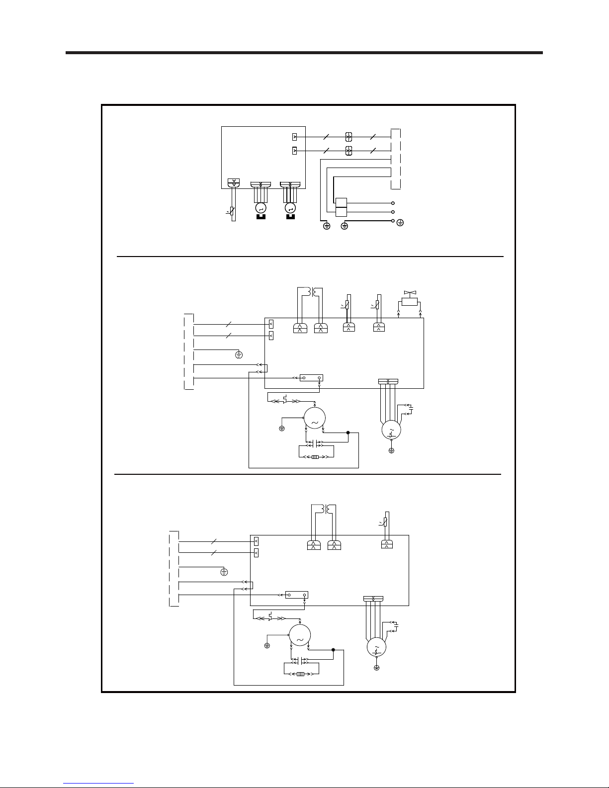
ELECTRIC DIAGRAM
Roof Top Air Conditioner(heat pump)
Roof Top Air Conditioner(cooling only)
- 2 -
BU
CN6
K101
RD
SAT
BU
YE
PTC
YEGN
WH
BK
G
TUBE SENSOR
RT1
AC-L
TUBE
FAN
C2
M1
FAN
G
YEGN
COMP.
R
C1
C(T)
S
YEGN
G
RD
BU
YE
BU
COMP
N7
INDOOR UNIT
CN5
MOTOR
I
II
TC
TR-IN
TRANSFORMER
TR-OUT
AP1 PRINTED CIRCUIT BOARD
OVERLOAD
PROTECTOR
CAP.
CAP.
J1
0
Notice: Use Copper Conductors Only.
CONNECTOR
MOTOR
STEPPING
YEGN(GN)
BN(BK)
BU(WH)
POWER
AP1
OUTDOOR UNIT
M1 M2
STEPPING
MOTOR
BK
WH
YEGN
L
N
G
SENSOR
ROOM TEMP.
TERMINAL
BLOCK
PRINTED CIRCUIT BOARD
CN6
SWING1 SWING2
CN5
0
RT1
ROOM
L
N
J1
CAP.
CAP.
PROTECTOR
OVERLOAD
AP1 PRINTED CIRCUIT BOARD
TR-OUT
TRANSFORMER
TR-IN
TC
II
I
MOTOR
CN5
INDOOR UNIT
N7
COMP
BU
YE
BU
RD
G
YEGN
S
C(T)
C1
R
COMP.
YEGN
G
FAN
M1
C2
FAN
TUBE
AC-L
RT1
SENSOR
G
BK
WH
YEGN
PTC
YE
BU
SAT
RD
K101
CN6
BU
TUBE
OUT TUBE
SENSOR
OUT TUBE
RT2
4YV
4-WAY
VALVE
4V N4
0
0
- 3 -
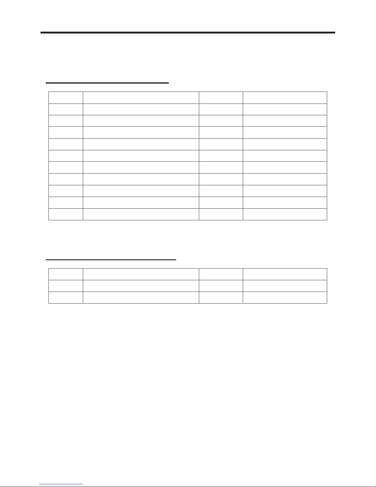
PACKING LIST
No. Name Quantity Remark
Sponge 1
Rubber gasket
Gasket1 1
42
Packing List of Outdoor Unit
Packing List of Indoor Unit
1
2
3
4
5
7
8
6
9
10
No. Name Quantity Remark
Ow ner' s Ma nu al
Bolt sub -assy M8X1 9 0
Spong e (air du ct)
Pla t e of a ir ve nt
Rem o te con trol YS1FAF
Dou ble -sid ed g u mm ed paper
Rem o te con trol holde r
AAA1 .5V batt eries
Tapp in g screw ST 4.2 X9 .5 TA
Sunk screw (remote control holder)
1
4
1
2
1
1
1
2
8
2
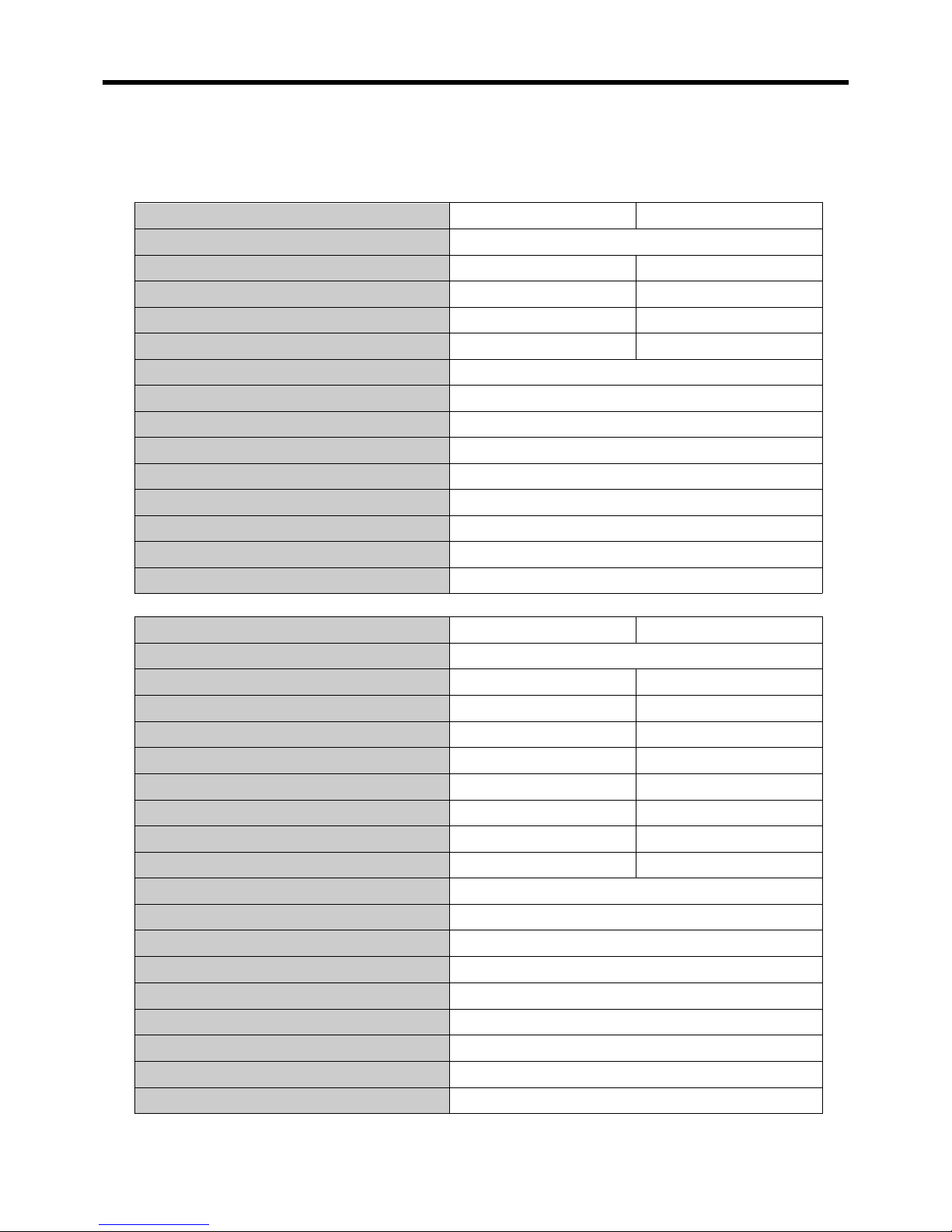
SPECIFICATIONS
- 4 -
● These specifications are for reference only. For actual data, please refer to the nameplate
on the back of the unit.
Power Supply (Ph/V/Hz)
Rated Cooling Capacity (BTU/h)
Cooling Power Input (Watts)
Rated Current Cooling (Amperage)
EER
Noise Level dB(A) (H/M/L)
CFM H/M/L
Product Dimensions (W” x H” x D”) (Indoor)
Package Dimensions (W” x H” x D”) (Indoor)
Product Dimensions (W” x H” x D”) (Outdoor)
Package Dimensions (W” x H” x D”) (Outdoor)
Net/Gross Weight (Lbs) (Indoor)
Net/Gross Weight (Lbs) (Outdoor)
Refrigerant Type
Model RVA-135R RVA-150R
1/115/60
13500 15000
15301350
12
10 (Btu/h)/W
353/306/259
26.26x19.57x3.78
28.94x22.64x5.91
40.79x22.56x14.72
45.39x27.87x18.31
11/14.3
95/122
R410A
13.6
9.8 (Btu/h)/W
/
Power Supply (Ph/V/Hz)
Rated Cooling Capacity (BTU/h)
Cooling Power Input (Watts)
Rated Current Cooling (Amperage)
EER
Rated Heating Capacity (BTU/h)
Heating Power Input (Watts)
Rated Current Heating (Amperage)
COP
Noise Level dB(A) (H/M/L)
CFM H/M/L
Product Dimensions (W” x H” x D”) (Indoor)
Package Dimensions (W” x H” x D”) (Indoor)
Product Dimensions (W” x H” x D”) (Outdoor)
Package Dimensions (W” x H” x D”) (Outdoor)
Net/Gross Weight (Lbs) (Indoor)
Net/Gross Weight (Lbs) (Outdoor)
Refrigerant Type
Model RVA-135RHP RVA-150RHP
1/115/60
13500 15000
1350 1530
13.612
9.8 (Btu/h)/W10 (Btu/h)/W
13500
10.6
353/306/259
26.26x19.57x3.78
28.94x22.64x5.91
40.79x22.56x14.72
45.39x27.87x18.31
11/14.3
95/122
R410A
15000
1200 1380
12.2
11.2 (Btu/h)/W 10.9 (Btu/h)/W
/
 Loading...