

Page 1
Change for Life
Recreational Vehicle
Owner's Manual
Operation & Installation
Thank you for choosing
Recreational Vehicle
manual carefully before operation and keep it for future reference.
Air Conditioner
Air Conditioner,Please read this owner’s
RVA-135R
RVA-135RHP
RVA-150R
RVA-150RHP
Models:
V.121210
Page 2

CONTENTS
1. A FEW WORDS ABOUT YOUR NEW AIR CONDITIONING UNIT .................................1
5. OPERATION OF WIRELESS REMOTE CONTROL .......................................................5
6. CONTROL PANEL ...........................................................................................................9
...................................................................179. NORMAL MAINTENANCE PROCEDURES
......................................................................................................22. ELECTRIC DIAGRAM
7. INSTALLATION INSTRUCTION.....................................................................................10
.................................................................................................14
STEP 3-ELECTRICAL WIRING
................................................................................15
STEP 4-COMPLETING THE INSTALLATION
............................................................................13
STEP 2-INSTALLING THE CEILING ASSEMBLY
......10
STEP 1-SELECTING AN INSTALLATION LOCATION & INSTALLING THE ROOF TOP AIR CONDITIONER
.......................................................................................168. TROUBLESHOOTING GUIDE
.................................................................................................................33. PACKING LIST
............................................................................................................44. SPECIFICATIONS
Page 3

A FEW WORDS ABOUT YOUR NEW
AIR CONDITIONING UNIT
ELECTRICAL
DATA
1.
All wiring must be complied with local and national electrical codes. All wiring
must be installed by qualified electricians. If you have
any questions about the
following instructions, contact a qualified
electrician.
2.
Check the available power supply and resolve any wiring problems BEFORE installing
and operating this unit.
3.
This air conditioner is designed to operate from a 115V AC, 60Hz, 1 Phase power
supply.
4.
The wiring diagrams are located on the cover of the control box. The assembly unit
wire diagrams are located on the ceiling panel.
- 1 -
Thank you for choosing the GREE Recreational Vehicle Air Conditioner.
This manual will supply you with all the information for installation, operation and maintenance.
Take a few minutes to discover how to get the most in cooling comfort and economic operation
from your new air conditioner.
Please keep this manual well for future reference.
Page 4
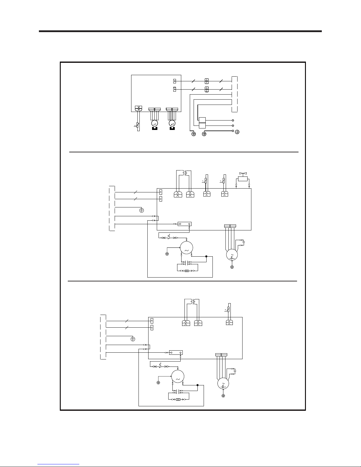
Ceiling Assembly
ELECTRIC DIAGRAM
Roof Top Air Conditioner(heat pump)
Roof Top Air Conditioner(cooling only)
- 2 -
BU
CN6
K101
RD
SAT
BU
YE
PTC
YEGN
WH
BK
G
TUBE SENSOR
RT1
AC-L
TUBE
FAN
C2
M1
FAN
G
YEGN
COMP.
R
C1
C(T)
S
YEGN
G
RD
BU
YE
BU
COMP
N7
INDOOR UNIT
CN5
MOTOR
I
II
TC
TR-IN
TRANSFORMER
TR-OUT
AP1 PRINTED CIRCUIT BOARD
OVERLOAD
PROTECTOR
CAP.
CAP.
J1
0
Notice: Use Copper Conductors Only.
CONNECTOR
MOTOR
STEPPING
YEGN(GN)
BN(BK)
BU(WH)
POWER
AP1
OUTDOOR UNIT
M1 M2
STEPPING
MOTOR
BK
WH
YEGN
L
N
G
SENSOR
ROOM TEMP.
TERMINAL
BLOCK
PRINTED CIRCUIT BOARD
CN6
SWING1 SWING2
CN5
0
RT1
ROOM
L
N
J1
CAP.
CAP.
PROTECTOR
OVERLOAD
AP1 PRINTED CIRCUIT BOARD
TR-OUT
TRANSFORMER
TR-IN
TC
II
I
MOTOR
CN5
INDOOR UNIT
N7
COMP
BU
YE
BU
RD
G
YEGN
S
C(T)
C1
R
COMP.
YEGN
G
FAN
M1
C2
FAN
TUBE
AC-L
RT1
SENSOR
G
BK
WH
YEGN
PTC
YE
BU
SAT
RD
K101
CN6
BU
TUBE
OUT TUBE
SENSOR
OUT TUBE
RT2
4YV
4-WAY
VALVE
4V N4
0
0
Page 5
- 3 -
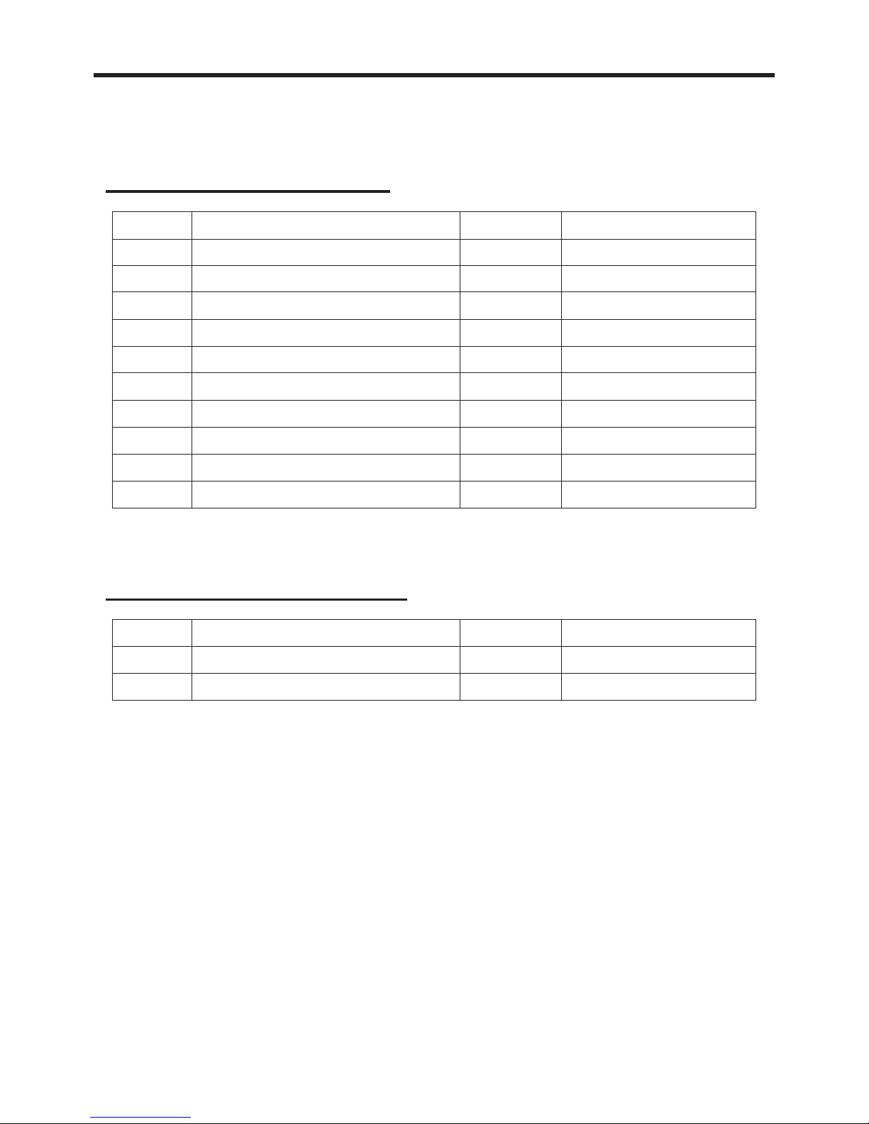
PACKING LIST
No. Name Quantity Remark
Sponge 1
Rubber gasket
Gasket1 1
42
Packing List of Outdoor Unit
Packing List of Indoor Unit
1
2
3
4
5
7
8
6
9
10
No. Name Quantity Remark
Ow ner' s Ma nu al
Bolt sub -assy M8X1 9 0
Spong e (air du ct)
Pla t e of a ir ve nt
Rem o te con trol YS1FAF
Dou ble -sid ed g u mm ed paper
Rem o te con trol holde r
AAA1 .5V batt eries
Tapp in g screw ST 4.2 X9 .5 TA
Sunk screw (remote control holder)
1
4
1
2
1
1
1
2
8
2
Page 6
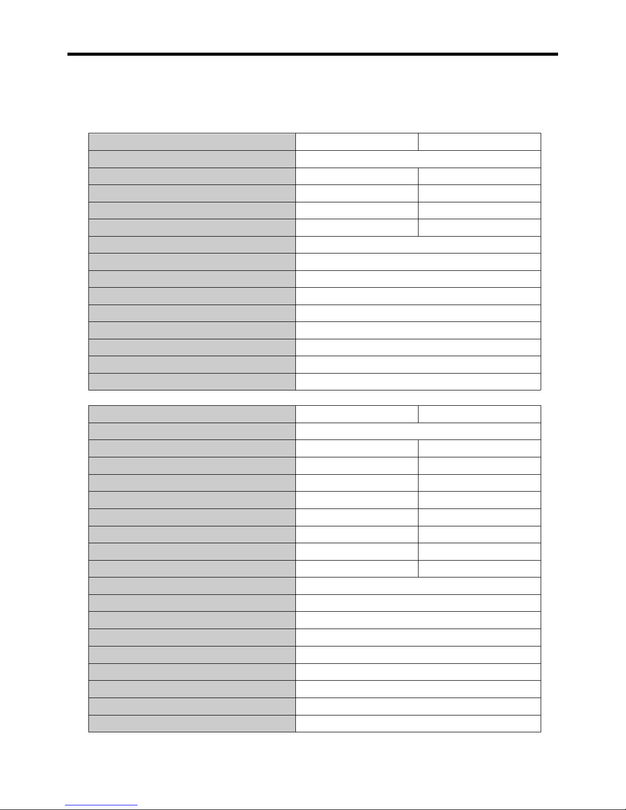
SPECIFICATIONS
- 4 -
● These specifications are for reference only. For actual data, please refer to the nameplate
on the back of the unit.
Power Supply (Ph/V/Hz)
Rated Cooling Capacity (BTU/h)
Cooling Power Input (Watts)
Rated Current Cooling (Amperage)
EER
Noise Level dB(A) (H/M/L)
CFM H/M/L
Product Dimensions (W” x H” x D”) (Indoor)
Package Dimensions (W” x H” x D”) (Indoor)
Product Dimensions (W” x H” x D”) (Outdoor)
Package Dimensions (W” x H” x D”) (Outdoor)
Net/Gross Weight (Lbs) (Indoor)
Net/Gross Weight (Lbs) (Outdoor)
Refrigerant Type
Model RVA-135R RVA-150R
1/115/60
13500 15000
15301350
12
10 (Btu/h)/W
353/306/259
26.26x19.57x3.78
28.94x22.64x5.91
40.79x22.56x14.72
45.39x27.87x18.31
11/14.3
95/122
R410A
13.6
9.8 (Btu/h)/W
/
Power Supply (Ph/V/Hz)
Rated Cooling Capacity (BTU/h)
Cooling Power Input (Watts)
Rated Current Cooling (Amperage)
EER
Rated Heating Capacity (BTU/h)
Heating Power Input (Watts)
Rated Current Heating (Amperage)
COP
Noise Level dB(A) (H/M/L)
CFM H/M/L
Product Dimensions (W” x H” x D”) (Indoor)
Package Dimensions (W” x H” x D”) (Indoor)
Product Dimensions (W” x H” x D”) (Outdoor)
Package Dimensions (W” x H” x D”) (Outdoor)
Net/Gross Weight (Lbs) (Indoor)
Net/Gross Weight (Lbs) (Outdoor)
Refrigerant Type
Model RVA-135RHP RVA-150RHP
1/115/60
13500 15000
1350 1530
13.612
9.8 (Btu/h)/W10 (Btu/h)/W
13500
10.6
353/306/259
26.26x19.57x3.78
28.94x22.64x5.91
40.79x22.56x14.72
45.39x27.87x18.31
11/14.3
95/122
R410A
15000
1200 1380
12.2
11.2 (Btu/h)/W 10.9 (Btu/h)/W
/
Page 7
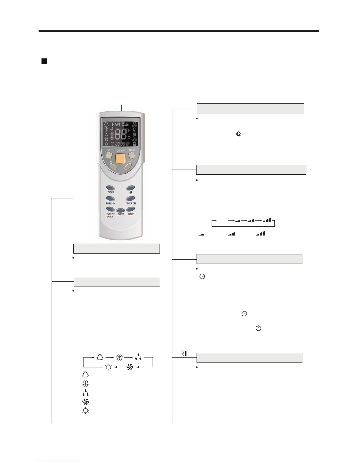
Signal Transmitter
OPERATION OF WIRELESS REMOTE CONTROL
Name and Function of Wireless Remote Control
Note: This wireless remote control is universal,and it could be used for many other
models. The buttons that are not relevant to this unit will not be described below.
ON/OFF button
ON/OFF
Remote Control
AUTO
COOL
DRY
FAN
Press this button to turn on the unit,
press it again to turn off the unit.
(Only available for heating unit)
HEAT
under other modes.
MED
Press this button, AUTO, COOL,
DRY, FAN, HEAT mode can be
selected circularly. It is defaulted
AUTO mode after powering on the
unit while the setting temperature
will not be displayed. The initial
MODE button
MODE
Press SLEEP button to select sleep on
or sleep off. It is defaulted sleep off after
powering on. will be displayed once
sleep function is set on. The sleep function
is not available under FAN or AUTO mode.
SLEEP button
SLEEP
Press this button, AUTO,LOW,MED,HIGH
speed can be circularly selected. After
FAN button
FAN
powering on the unit, auto fan speed is
defaulted.Under DRY mode, only low fan
speed can be set up.
LOW HIGH
Press this button, the clock can be set up,
blinks and displays.Within 5 seconds,
CLOCK button
SWING button
CLOCK
the value can be adjusted by pressing +
or - button,if consecutively press this
under HEAT mode, 25℃(77 F)
o
setting temperature is 28℃(82 F)
o
AUTO
button for more than 2 seconds, the value
during blinking, will be displayed and
the clock setting is done. It is defaulted
displaying 12:00 and after powering
be displayed.
on. Either clock time or timer time could
When it is pressed,the louvers start to
rotate automatically and stop when
repressed.
- 5 -
will be fast increasing. Press CLOCK again
Page 8
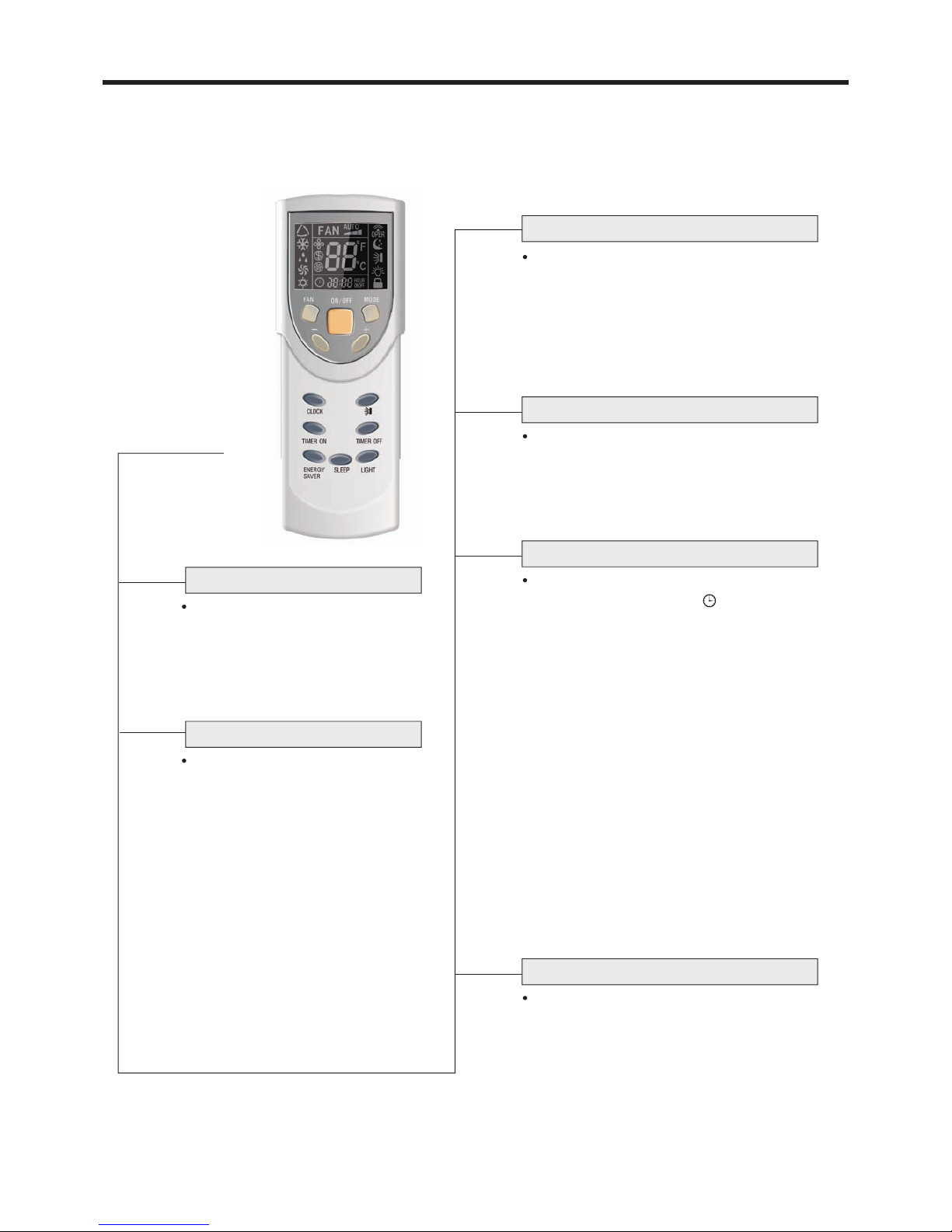
Remote Control
ENERGY SAVER button
LIGHT button
+
+ button
Press this button to increase setting
temperature, hold for more than 2 seconds
to rapidly increase setting temperature.In
AUTO mode, setting temperature is not
adjustable.Setting temperature Range of
- button
-
TIMER ON button
At unit off, press TIMER ON button,HOUR
At unit on, press TIMER OFF button to enter
into TIMER OFF setting.The method of setting
up is the same as TIMER ON.
ON will blink and display, will be
concealed in the TIMER ON setting. During
adjusted by pressing + or - button,every
press of this button, 0.5hour will be increased
or decreased, by continuous pressing the +
or - button, 2 seconds later,the value will be
changed quickly, 0.5hour will be changed in
every 0.25second automatically by the
remote control. During blinking,press the
TIMER ON button to confirm the time.After
TIMER ON set up, with repressing the TIMER
ON button, the TIMER ON setting will be
canceled. After powered on,no timer is
defaulted, HOUR ON(OFF) will not display,
and only the clock is displayed.After the timer
reached the setting time, HOUR ON(OFF)
will conceal.Before setting the timer,please
adjust the clock to the current actual time.
TIMER
ON
TIMER OFF button
TIMER
OFF
5 seconds blinking,the value can be
Press this button to decrease setting
temperature, hold for more than 2 seconds
to rapidly decrease setting temperature.
ENERGY
In AUTO mode, setting temperature is
not adjustable.
SAVER
Under the COOL and DRY mode,
press this button once, the unit will
enter ENERGY SAVER mode.Press
this button again, the unit will exit
ENERGY SAVER mode.
LIGHT
Press this button to turn ON or OFF
the light or display on the unit.
The light or display is defaulted on
after powering on the unit.
Celsius degree: 16-30 ℃, Fahrenheit degree:
61-86 F.
o
Note: This wireless remote control is universal,and it could be used for many
other models.
The buttons that are not relevant to this unit will not be described below.
- 6 -
Page 9
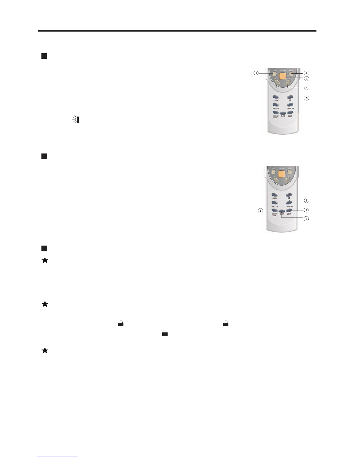
Guide for Operation - General Operation
1. After powering on,press ON/OFF button,the unit will start to run.(Note:When
it is powered on,the guide louver of indoor unit will close automatically.)
2. Press MODE button to select desired running mode.
3. Pressing + or - button, to set the desired temperature.
4. Press FAN button to set AUTO,LOW,MED or HIGH fan speed.
Guide for Operation - Optional Operation
1. Press SLEEP button, to set sleep.
2. Press TIMER ON and TIMER OFF button,to set the scheduled timer on
or timer off.
3. Press LIGHT button, to control the on and off of the light or display
on the unit.
4. Press ENERGY SAVER button to activate the function.
Introduction for Special Function
About AUTO mode
When AUTO mode is selected,the setting temperature will not be displayed on the
remote control,the unit will be in accordance with the room temperature,and automatically
select the suitable running method to make ambient comfortable.
About Lock
Press + and - buttons simultaneously to lock or unlock the keyboard of the remote control.
About Switch Between Fahrenheit and Centigrade
At unit off,press MODE and - button simultaneously to switch between ℃ and ℉.
If the keyboard is locked, will be displayed on it,press any button, will blink
three times. If the keyboard is unlocked, the will not display.
- 7 -
5. Pressing button, to select the swing.
Page 10
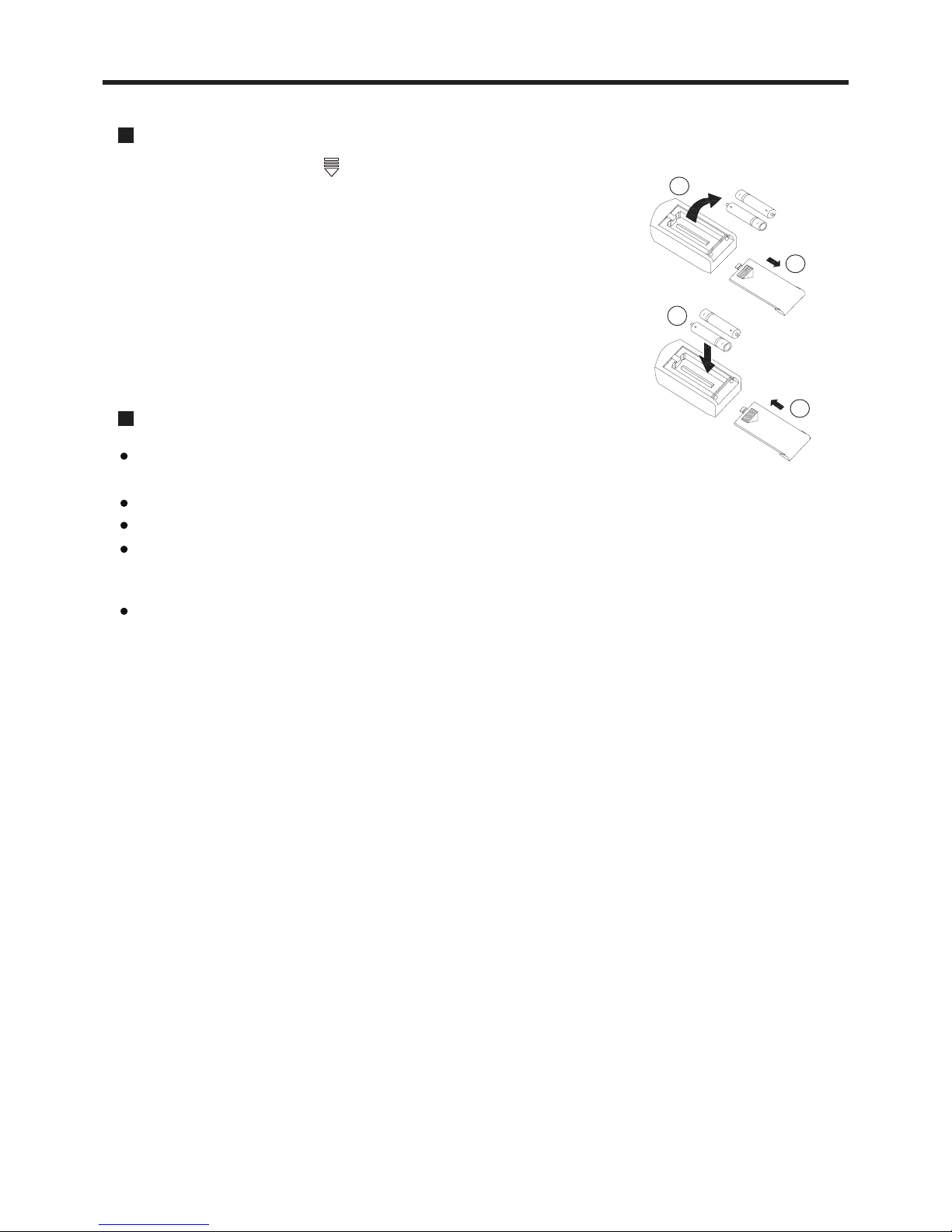
Changing Batteries
1. Slightly press the place with , and push the cover along the arrow.
2. Take out the used batteries. (As show in figure)
3. Insert two new AAA1.5V batteries, and pay attention to the polarity.
(As show in figure)
4. Push the back cover of remote control. (As show inf figure)
NOTE:
When changing the batteries, do not mix used and new batteries,
do not mix different batteries, otherwise, it can cause the malfunction
of the remote control.
If the remote control will not be used for a long time,please take out
batteries to prevent any damage from liquid leakage.
The operation should be in its receiving range.
It should be placed 1m away from the TV or stereo sound sets.
If the remote control can not work normally, please take out the
batteries, then reinsert 30S after, if it does not run normally, change
the batteries.
Sketch map for
changing batteries
2
1
3
4
Notices
Be sure that there are no obstructions between receiver and remote
control, Don't drop or throw the remote control, Don't let any liquid get
into the remote control or put the remote control directly under the
sunlight or any place where is very hot.
- 8 -
Page 11
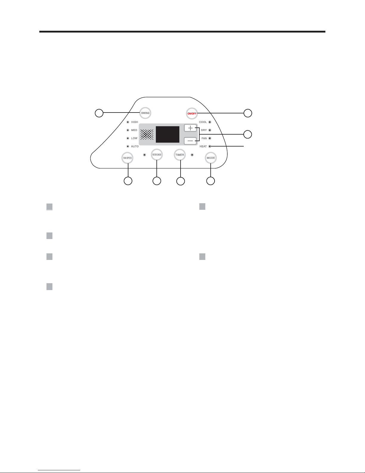
CONTROL PANEL
Note: If the remote control is missing , operate on the control panel.
3 46
2
1
4
5
Not available for cooling
only model
1
ON/OFF button
Operation starts when pressing this button, and
stops when pressing this button again.
2
SWING button
Activate the automatic air swing function.
3
FAN SPEED button
Select the fan speed AUTO, LOW, MED and HIGH
in sequence.
6
FILTER CHECK button
This feature is a reminder of cleaning the air
filter(normal maintenance) for more efficient
operation. The light will turn on automatically
after the fan works more than 250 hours.
If the light is on, turn off and power off the
unit, take the air filter out and clean it, then
re-install the air filter, power on and turn
on the unit, the light will still be on, press
FILTER CHECK button,the light will
turn off.
4
(+/-) / TIMER button
Press the + button to increase the set(operating)
temperature of the unit,and press the - button to
decrease the set(operating) temperature of the
unit. the temperature setting range is from 16~30℃
Press TIMER button,then press +/- to increase
and decrease the time setting.If the time setting
is no more than 10 hours,the increment/decrement
is 0.5 hour by each press,if more than 10 hours,
the increment/decrement is 1 hour by each press.
The time setting range is 0.5~24 hours.
o
(61~86 F).
- 9 -
5
MODE button
Select the operation mode, AUTO, COOL,
DRY, FAN, HEAT(for heating model) or
AUTO, COOL, DRY, FAN(for cooling only
model).
Page 12
INSTALLA TION INSTRUCTION
BEFORE INSTALLATION
T
estrun the unit with proper power supply. Refer to the
operation instruction section in the Owner’s Manual
Operation & Installation. Make sure all the controls
operate correctly then disconnect the power supply
of the unit.
WARNING
!
Moving parts may cause personal injury. Be careful when test the unit. Do not operate the unit
with exterior cover removed.
STEP 1-SELECTING AN INSTALLATION LOCATION &
INSTALLING THE ROOF TOP AIR CONDITIONER
Your air conditioner has been designed for use in recreational vehicles.
Check the roof of the vehicle to determine if it can support both the roof top unit and the ceiling
assembly without additional support. Make sure the interior ceiling mounting area will not
interfere with existing structures.
Once the location for your air conditioner has been determined.A reinforced and framed roof
hole opening must be cut (if there is no hole) or you may use existing vent holes.
CASE A.
If a roof vent is already present in the desired mounting location for the air conditioner, the
following steps must be performed:
1.
Remove all screws which secure the roof vent to the vehicle.Remove the vent and any
additional trim. Carefully remove all chalking from around the opening so the surface is
clear.
2.
It may be necessary to seal some of the old roof vent mounting screw holes which may
fall outside of the air conditioner basepan gasket.
3.
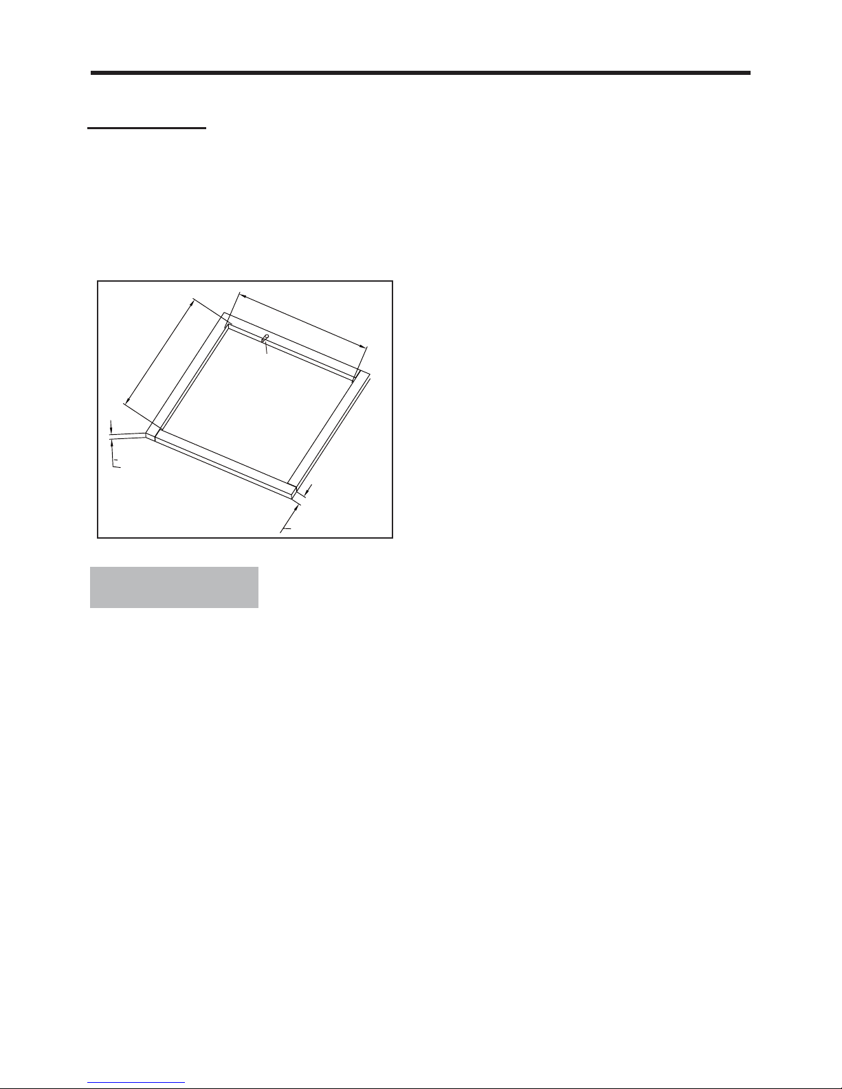
Examine the roof opening size, if the opening is small than 14’’x14’’, the opening must
be enlarged. If the opening exceeds 14’’x14’’, a mounting plate (frame) must be fabricated
to reduce the opening size (See Figure 1).
- 10 -
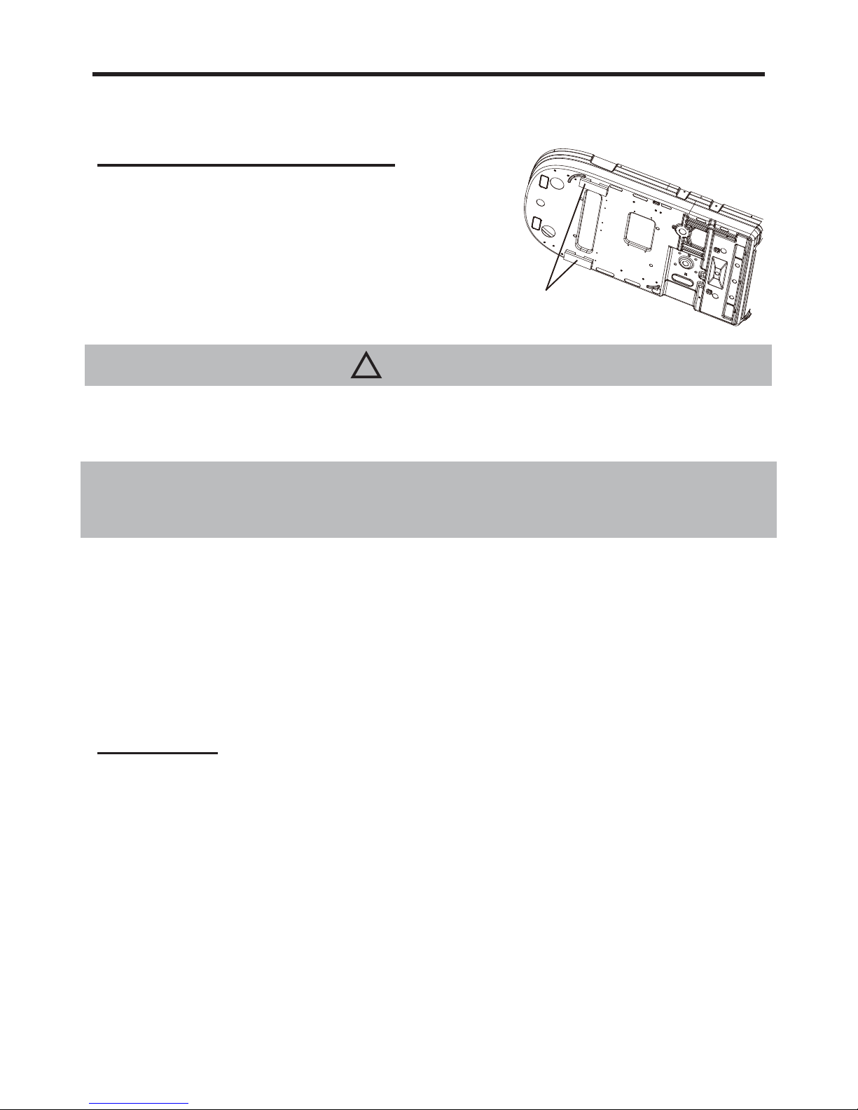
● Before installation, please do remove the auxiliary
sponge.
Before installation, please
do remove these auxiliary
sponges
Page 13
14''
14''
3
4
''
1''
Figure 1
If a roof vent opening is not used,a new opening(see figure 1)will be cut into the vehicl roof.
A matching opening will also have to be cut into the interior vehicle ceiling,be careful when
cutting the ceiling opening because if the ceiling opening is carpeted,snagging could occur. After
the opening in the roof and interior ceiling are the correct size,a framed support structure must
be placed between the exterior roof top and interior ceiling.The reinforced framed structure must
follow the follwing guidelines:
1. It must be capable of supporting both the
weight of the roof top air conditioner and
the interior ceiling assembly.
3.
There must be an opening through the
frame for the power supply wiring.Route
the supply wiring through the frame at the
same time the support frame is being
installed.
2.
It must be capable of holding the roof outer
surface and interior ceiling apart and
supporting them, so that when the roof top
air conditioner and ceiling assembly are
bolted together,no collapsing occurs. A
typical support frame is shown in Figure 1.
CAUTION
2. The roof top air conditioner must be mounted on a level plane from front to rear and side to
side when the vehicle is parked on a level plane. Figure 3 shows maximum allowable degrees
that the unit can be mounted above or below level.
3. If the roof of the vehicle is sloped (not level) such that the roof top air conditioner cannot be
mounted within the maximum allowable degree specifications, an exterior leveling shim will
need to be added to make the unit level. A typical leveling shim is shown in Figure 4.
4.
Once the roof top air conditioner has been leveled, some additional shimming may be required
above the interior ceiling assembly. The roof top air conditioner and the interior ceiling assembly
must be square with each other before they are secured together.
5. After the mounting hole area is properly prepared, remove the carton and shipping pads from
around the roof top air conditioner. Carefully lift the unit on top of the vehicle. Do not use the outer
plastic shroud for lifting. Place the roof top air conditioner over the prepared mounting hole.
6. The point end (nose) of the shroud must face toward the front of the vehicle.
1.
Gasket is standard accessory which should be properly sticked before installation of the roof
top air conditioner (See Figure 2).
Hole for
Wires
CASE B.
- 11 -
Page 14

14''
14''
NOTE AIR CONDITIONER DIMENSIONS (ROOF OF UNIT)
Above or Below
Level 10° Max
Level
Level
Level
Above Level 10° Max
Below Level 0° Max
Figure 3
Level
Height Varies to Make Unit Level
Figure 4
39.3''
14''
3.3''
20.9''
16.1''
14''x14
''
9.2''
OPENING
3.3''
14''
Gasket
Location for
Location for
Rubber Locator
Stick
Figure 2
Location for
Rubber Locator
- 12 -
Page 15
STEP 2-INSTALLING THE CEILING ASSEMBLY
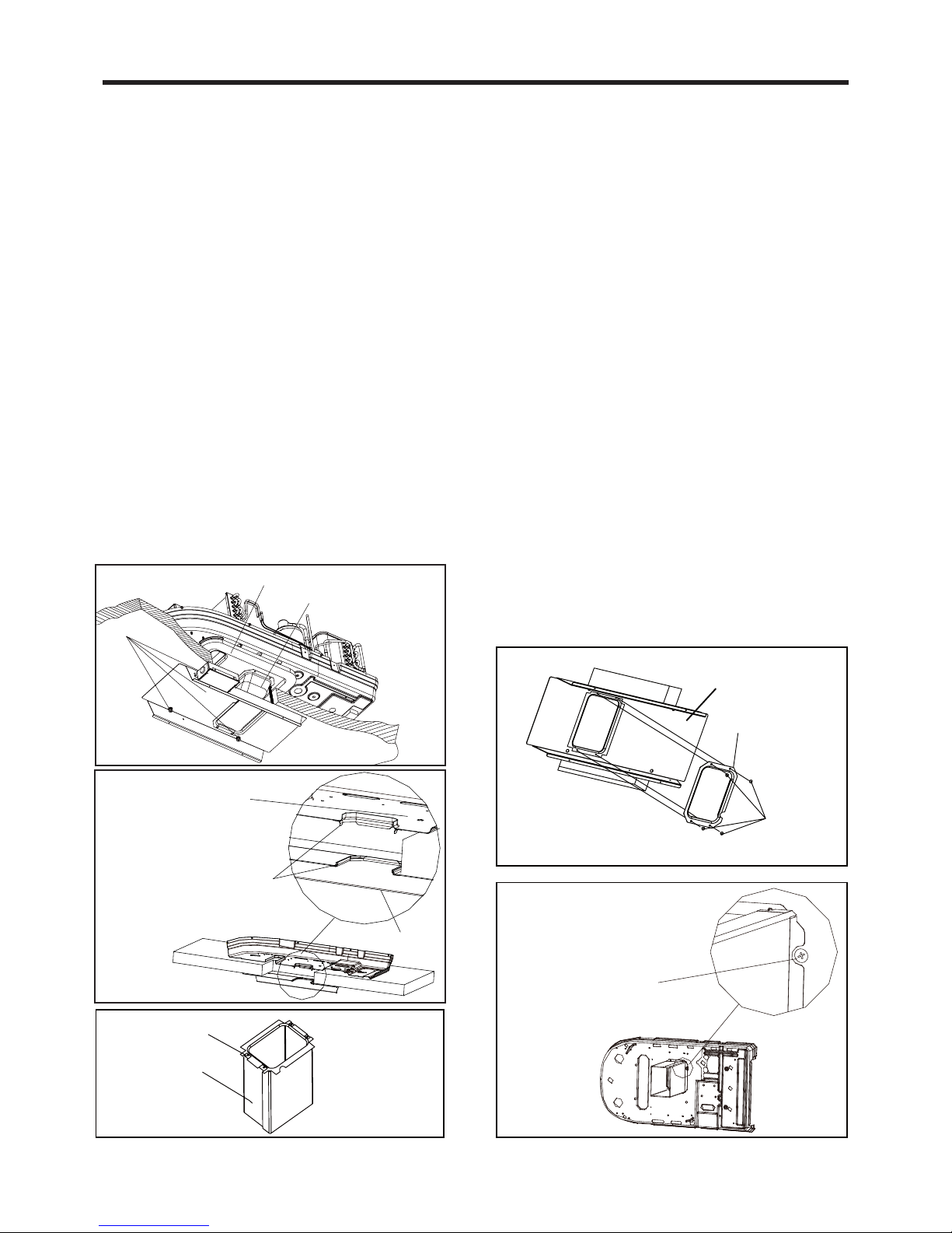
Make sure that you have properly matched the roof top air conditioner and interior ceiling
assembly.The following step by step instructions must be performed in the following sequence
to ensure proper installation.
2.
Remove the ceiling grille from the ceiling
assembly.
4.
Before lifting the ceiling assembly, pull
the fabric duct collar so it hangs out of
the way and does not get caught under
the ceiling assembly frame.
1.
Carefully take the ceiling assembly out
with the ceiling assembly).
of the carton (The remote control packed
3.
mounted to the roof top air conditioner,
plate (see Figure 5 and Figure 5-1 and
Figure 5-2).
Before the ceiling assembly can be
to the basepan of the roof top air
the fabric duct collar must be fastened
conditioner with 4 screws by upper duct
5.
Secure the ceiling assembly frame to the
gasket has been evenly compressed.
roof top air conditioner with the mounting
bolts(see Figure 5).You must start (thread)
themounting bolts by hand to avoid
cross-threading. DO NOT START THE
MOUNTING BOLTS WITH AN AIR GUN.
The mounting bolts should be tightened,
process is completed when the basepan
6.
opening (see Figure 5 and Figure 5-1).
Pull the fabric duct collar through the
the four corners to extend below the duct
ceiling assembly frame opening and pull
7.
6).Trim any excess fabric that may extend
beyond edge of bottom duct plate.
Fasten each side of the fabric duct with
fitting the bottom duct plate to the ceiling
assembly frame with 4 screws (see Figure
4 Screws
Figure 6
Frame
Bottom Duct
Plate
Figure 6-1
Please pay attention to
match the gap with the
riveted nut during installation
Upper Duct Plate
Fabric Duct
Figure 5-2
Figure 5-1
This Should Be
Assembled.
Installation Way of
Ventilation Opening Clamp
Indoor Unit
Outdoor Unit
4 Bolts
Figure 5
Gasket
Fabric Duct Collar
- 13 -
Page 16

STEP 3-ELECTRICAL WIRING
ROUTING 115V AC WIRING
!
WARNING
Make sure that all power supply to the unit is disconnected before performing any work on the
unit to avoid the possibility of shock or injury and/or damage to the equipment. After the interior
ceiling assembly frame is properly secured to the roof top air conditioner, the following electrical
connections must be performed.
Figure 7
2 Screws
Come From Roof
Power Cord
Ground Wire
(Green Wire)
Top Air
Power Supply
Cord
Conditioner
Strain
Relief
(Clamp)
Strain
Relief
(Clamp)
Black Wire
White Wire
Figure 8
Control Line Comes
From Roof Top Air
Conditioner
Display Box
of Ceiling
Assembly
Connector
Clamp
Figure 9
1.
Route a copper ,with ground, supply wiring
with minimum #12AWG for both 13.5KBtu/h
and 15KBtu/h unit, the wiring from its power
source to the junction box. Do not attach
them at this time.
2. Take the roof top air conditioner power cord
to connect to the side of the junction box.
3. Remove the junction box cover (2 screws).
Take the power cord and make it get into the
box through the strain relief that is provided
(see Figure 7).
4. Connect the power cord to the black,white
and ground wires found in the junction box
with a terminal board. CAUTION Connect black
wire to black wire,white wire to white wire
and the ground wire to earth.(see Figure 8).
5. Tighten the strain relief clamp to secure the
supply power cord.DO NOT OVERTIGHTEN.
Reinstall the junction box cover.
Frame
Junction Box
Cover
6. Connect the two connector and secure the
clamp (see Figure 9 and Figure 9-1).
Clamp
Two connector
(white to white,black to black)
Figure 9-1
- 14 -
Page 17

Make sure the guide louver and the filters are properly positioned in the ceiling grille.
2.
Secure the ceiling grille to the ceiling assembly frame with 4 screws.(see Figure 10).
3.
Switch on the power supply and check the unit work or not.
4.
Check the thermostat position. Make sure the thermostat is routed through the holding guide
and is not touching any metal surface.
1.
STEP 4-COMPLETING THE INSTALLATION
To complete the installation and system checkout requirements, the following steps must be
performed.
Frame
Ceiling Grille
4 Screws
Figure 10
- 15 -
Page 18
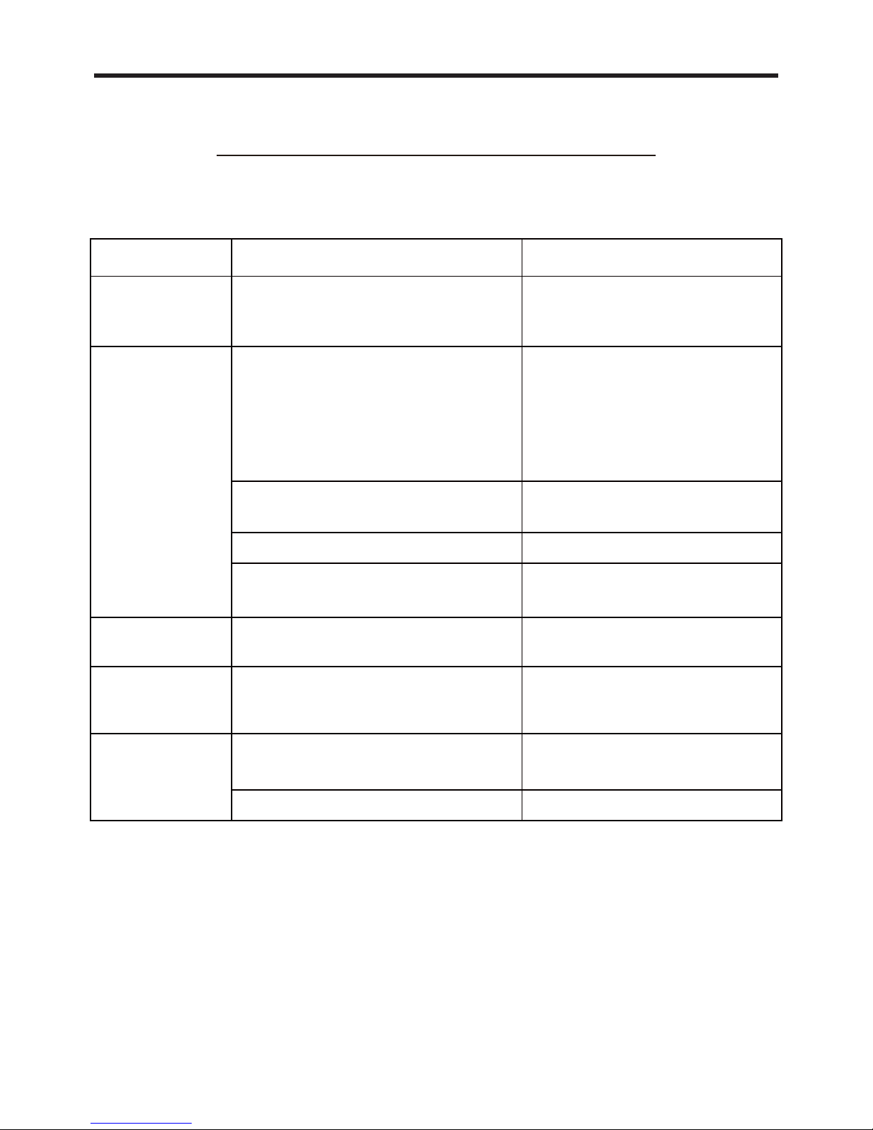
TROUBLESHOOTING GUIDE
If you have problems with your recreational vehicle air conditioner, check this guide before
contacting your service representative.
TROUBLE SOLUTIONPOSSIBLE CAUSE
The unit can
not start
The unit may not be connected to the
power supply correctly.
Check the power supply of the
vehicle and make sure it is
provided correctly.
The unit can not
cool the room
The roof top air conditioner is not
level.
The temperature setting is too high.
The air filter is dirty.
Mount the roof top air conditioner
as level as possible from front to
rear and side to side when the
vehicle is parked.Make sure that
the mounting of the air conditioner
is correct and level.
Reset the remote control to a lower
temperature setting.
Remove and clean the filter.
Allow a sufficient amount of time for
unit to cool the room.
Mounting bolts should be tightened
evenly by compressing the basepan
gasket.
The filter is dirty.
Remove and clean the filter.
The unit is making
The room was already very hot before
The unit is click and gurgle.
The basepan gasket has not been
evenly compressed.
The temperature is low inside.
the unit was turned on.
noise
The unit has water
dripping inside
The unit has ice
or frost on the
coils
Select FAN mode at HIGH fan
These noise are normal during the
operation of the unit.
speed.
- 16 -
Page 19
NORMAL MAINTENANCE PROCEDURES
ACTIVETY
FREQUENCY
Twice a year.Remove the cover and wash the condenser coil
Clean the filter
(More frequent cleaning may be necessary light on.
depending on the air quality)
When the air conditioner FILTER CHECK
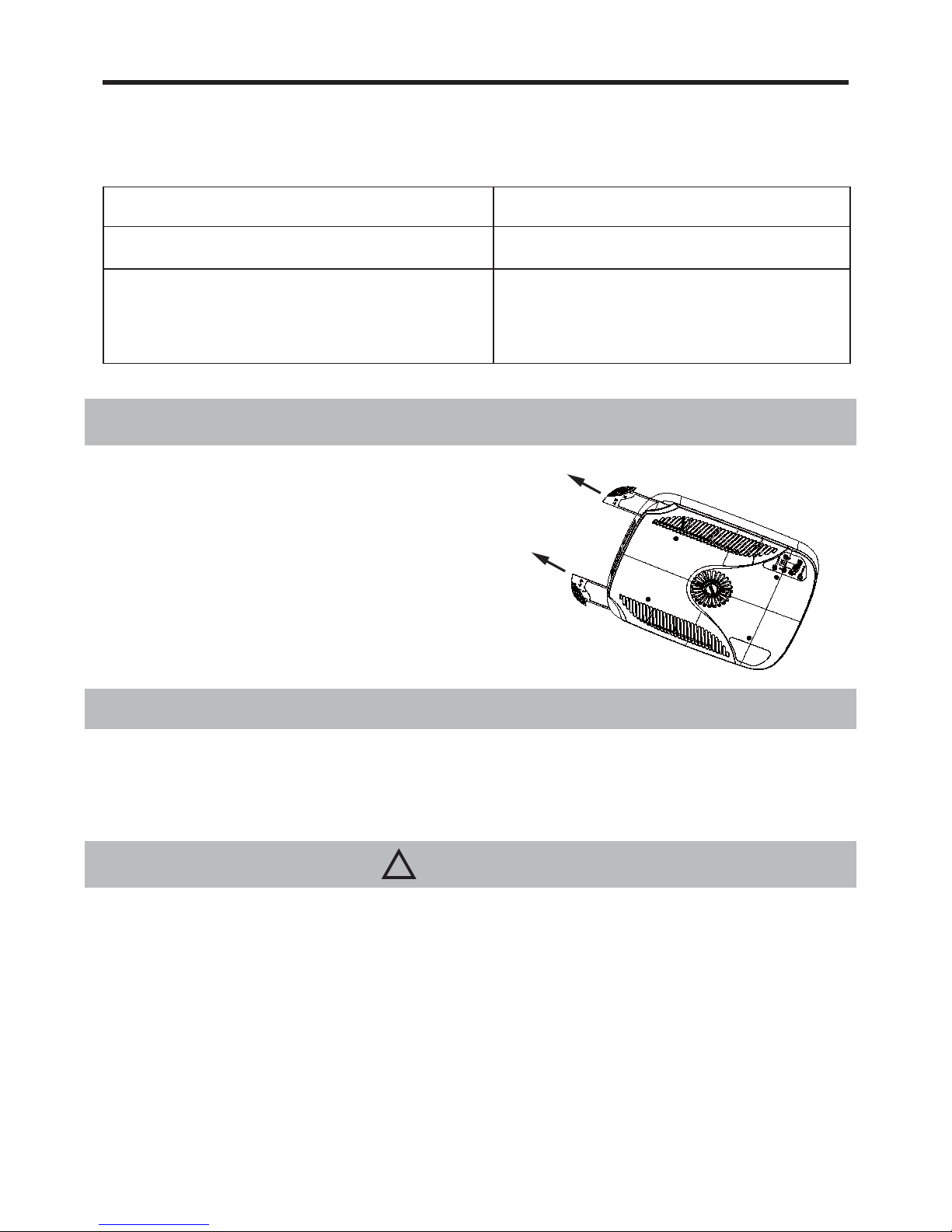
HOW TO REMOVE THE AIR FILTER
Remove the air filters by pulling them as illustrated below.
HOW TO CLEAN THE AIR FILTER
WARNING
!
FAILURE TO FOLLOWING INSTRUCTIONS COULD RESULT IN SERIOUS PERSONAL INJURY
2.
Be careful when you maintain the refrigeration system, which has the high internal pressure.
1. Don’t touch the capacitor terminals without the electric discharge ,the capacitor still may have
the high voltage even though the power supply is turned off.
Wash away dust from the air filters with clean water or vacuum the filter with an electric household
vacuum cleaner.
- 17 -
Page 20

 Loading...