

Gree VIR12HP115V1A, VIR18HP230V1A, VIR12HP230V1A, VIR09HP230V1A, VIR24HP230V1A Installation Manual
...
Models:
VIR09HP115V1A
VIR12HP115V1A
VIR09HP230V1A
VIR12HP230V1A
VIR18HP230V1A
VIR24HP230V1A
VIR30HP230V1A
VIR36HP230V1A
HIGH-WALL DUCTLESS
AIR CONDITIONING & HEATING SYSTEM
INSTALLATION MANUAL

Table of Contents
Safety Precautions . . . . . . . . . . . . . . . . . . . . . . . . . . . . . . . . . . . . . . . . . . . 2-3
Nomenclature . . . . . . . . . . . . . . . . . . . . . . . . . . . . . . . . . . . . . . . . . . . . . . . . 4
System Requirements . . . . . . . . . . . . . . . . . . . . . . . . . . . . . . . . . . . . . . . . . . 5
Suggested Tools . . . . . . . . . . . . . . . . . . . . . . . . . . . . . . . . . . . . . . . . . . . . . . 6
Part Names . . . . . . . . . . . . . . . . . . . . . . . . . . . . . . . . . . . . . . . . . . . . . . . . . . 7
Installation Site Instructions . . . . . . . . . . . . . . . . . . . . . . . . . . . . . . . . . . . 8 -9
Indoor Unit Installation . . . . . . . . . . . . . . . . . . . . . . . . . . . . . . . . . . . . . 10-11
Outdoor Unit Installation . . . . . . . . . . . . . . . . . . . . . . . . . . . . . . . . . . . 12-13
Piping Installation . . . . . . . . . . . . . . . . . . . . . . . . . . . . . . . . . . . . . . . . . 14 -17
Power and Wiring Installation . . . . . . . . . . . . . . . . . . . . . . . . . . . . . . . 18 -20
Testing and Inspection . . . . . . . . . . . . . . . . . . . . . . . . . . . . . . . . . . . . . 21-23
Troubleshooting . . . . . . . . . . . . . . . . . . . . . . . . . . . . . . . . . . . . . . . . . . . 24-25
Diagnostic Codes . . . . . . . . . . . . . . . . . . . . . . . . . . . . . . . . . . . . . . . . . . 26-28
Care and Cleaning . . . . . . . . . . . . . . . . . . . . . . . . . . . . . . . . . . . . . . . . . . . 29
Thank you for choosing a Vireo Heat Pump
for your customer.
Please read this installation manual carefully before installing and starting up the
Vireo System. Take a moment to fill out the product and installation form on the
back cover. Retain both the manual and installation record for future reference.
2
SAFETY PRECAUTIONS
Please read the following before operation.
Recognize safety information. This is the safety-alert symbol. When you see this
symbol on the unit and in instructions or manuals, be alert to the potential for personal
injury. Understand these signal words: DANGER, WARNING, and CAUTION. These
words are used with the safety-alert symbol.
DANGER identifies the most serious hazards which will result in severe personal injury
or death.
WARNING signifies hazards which could result in personal injury or death.
CAUTION is used to identify unsafe practices which may result in minor personal
injury or product and property damage.
NOTE is used to highlight suggestions which will result in enhanced installation,
reliability, or operation.
This appliance is not intended for use by children without responsible adult supervision.
Proper care should be taken to ensure safety.
Heat pumps, air conditioners & heating equipment should be installed, started up, and
serviced only by qualified installers and service technicians. Air conditioning, heat pumps
and refrigeration systems are hazardous due to high voltage electrical components,
high refrigerant pressures, and moving parts.
N
O
T
E
:
Y
o
u
r
a
c
t
u
a
l
a
i
r
c
o
n
d
i
t
i
o
n
i
n
g
&
h
e
a
t
i
n
g
s
y
s
t
e
m
a
n
d
r
e
l
a
t
e
d
d
e
v
i
c
e
s
m
a
y
d
i
f
f
e
r
f
r
o
m
t
h
e
i
m
a
g
e
s
s
h
o
w
n
i
n
t
h
i
s
m
a
n
u
a
l
.
W
A
R
N
I
N
G
W
A
R
N
I
N
G
SAFETY PRECAUTIONS
• The unit should be installed and serviced only by trained, qualified installers and service
technicians. Untrained personnel can perform basic maintenance functions such as
cleaning coils. All other operations should be performed by trained service personnel.
• Owner should be cautioned that children should not play with the appliance.
ELECTRICAL SHOCK HAZARD
Failure to follow this warning could result in personal injury or death.
• Before installing, servicing or modifying the system, the main electrical disconnect
switch must be in the OFF position. There may be more than one disconnect switch.
Lock out and tag all switches with a warning label.
General Safety Precautions
• A dedicated power supply circuit should be used in accordance with local electrical
safety regulations and National Electrical Codes (NEC).
• Ensure that the entire system is properly grounded.
• Use a properly sized circuit breaker to protect equipment against short circuit and
overload conditions.
• The system must be positioned at least 5 feet from combustible surfaces.
• Observe all local codes and regulations.
Installation Site Instructions
A proper installation site is vital for correct and reliable operation of the system.
Avoid the following installation locations :
• High heat sources, vapors, flammable gas or volatile liquids.
• High-frequency electro-magnetic waves, generated by radio equipment, welders
or medical equipment.
3
WARNING
CAUTION

4
NOMENCLATURE
Cooling Capacity
09 - 9,000 BTUH
12 - 12,000 BTUH
18 - 18,000 BTUH
24 - 24,000 BTUH
30 - 30,000 BTUH
36 - 36,000 BTUH
Series Designation
Revision Level
Style/Color Designation
Product Type
S - System
O - Outdoor units
H - Indoor High Wall
D - Indoor Duct
C - Indoor Cassette
F - Indoor Floor/Ceiling
Electrical Rating
230V - 208/230V 60Hz 1PH
Model Type
AC - Cooling Only
HP - Heat Pump
HC - Heat/Cool
115V - 115V 60Hz 1PH
Example: VIR24HP230V1AH
HVIR 24 HP 230V 1A
CROWN
RIO
TERRA
VIREO
5
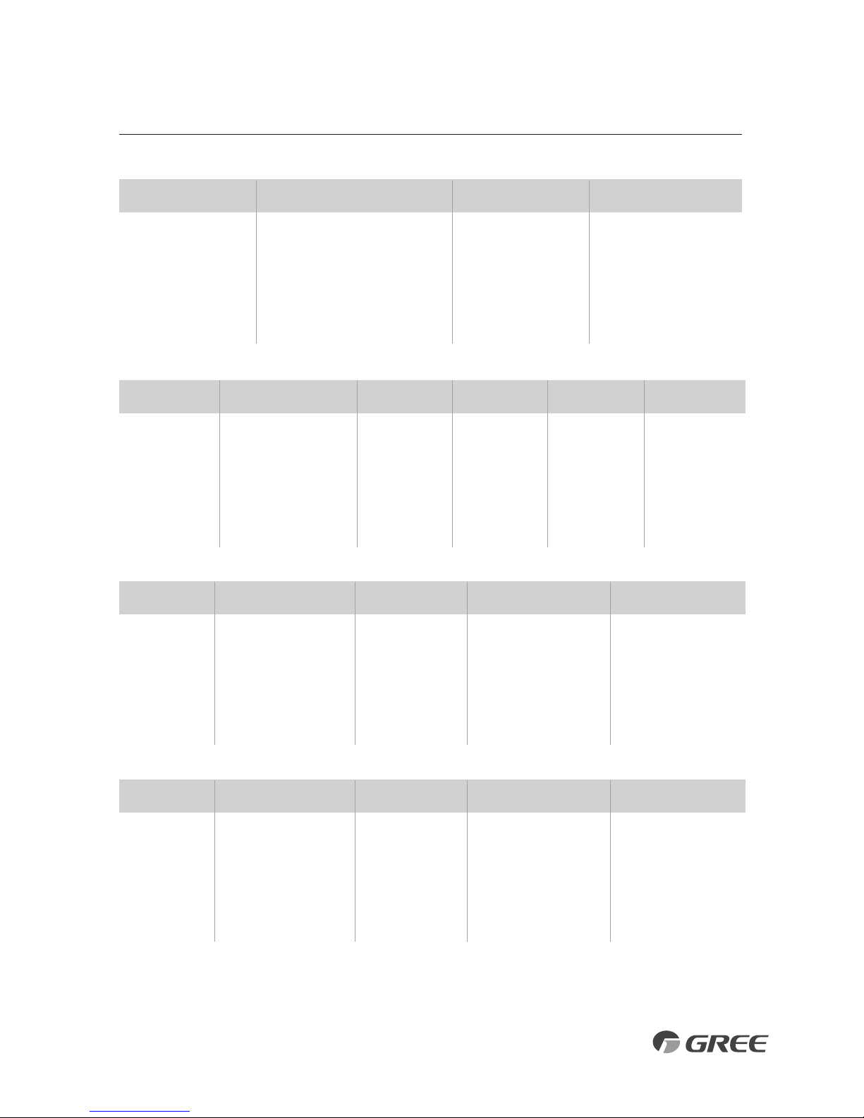
SYSTEM REQUIREMENTS
REFRIGERANT CHARGE
ELECTRICAL REQUIREMENTS
PIPE SIZE in (mm)
Notes: 1) System must be on a single dedicated circuit.
2) Main power is supplied to the outdoor unit.
3) Use table above to size over current protection.
4) Follow all local building codes and NEC (National Electrical Code) regulations.
Interconnecting Cable: Recommended cable - 14/4 AWG stranded bare copper conductors THHN 600V unshielded wire
Note: Use shield cable if installation is in close proximity of RF and EMI transmitting devices.
Condensate Drain Size: 5/8-in OD 7/16-in ID
U
nit Size
Voltage
L
iquid Line Suction/Gas Line
(BtuH)
9
,000 115v - 1ph 60hz 1/4 (6)
1
2,000 115v - 1ph 60hz 1/4 (6)
9,000 208/230v - 1ph 60hz 1/4 (6)
12,000 208/230v - 1ph 60hz 1/4 (6)
18,000 208/230v - 1ph 60hz 1/4 (6)
24,000 208/230v - 1ph 60hz 1/4 (6)
30,000 208/230v - 1ph 60hz 1/4 (6)
36,000 208/230v - 1ph 60hz 1/4 (6)
3/8 (9.5)
1/2 (12)
3/8 (9.5)
1
/2 (12)
1
/2 (12)
5/8 (16)
5/8 (16)
5/8 (16)
Unit Size
Voltage
Min Line Max Line Max
(BtuH) Length Length
Elevation
9,000 115v - 1ph 60hz 10 (3) 50 (15)
12,000 115v - 1ph 60hz 10 (3) 50 (15)
9,000 208/230v - 1ph 60hz 10 (3) 50 (15)
12,000 208/230v - 1ph 60hz 10 (3) 66 (20)
18,000 208/230v - 1ph 60hz 10 (3) 82 (25)
24,000 208/230v - 1ph 60hz 10 (3) 82 (25)
30,000 208/230v - 1ph 60hz 10 (3) 100 (30)
36,000 208/230v - 1ph 60hz 10 (3) 100 (30)
Unit Size
Voltage
Refrigerant Factory System Additional
(BtuH) Type Charge oz (kg) Charge oz/ft (g/m)
9,000 115v - 1ph 60hz R410A
12,000 115v - 1ph 60hz R410A
9,000 208/230v - 1ph 60hz R410A
12,000 208/230v - 1ph 60hz R410A
18,000 208/230v - 1ph 60hz R410A
24,000 208/230v - 1ph 60hz R410A
30,000 208/230v - 1ph 60hz R410A
36,000 208/230v - 1ph 60hz R410A
Unit Size
Voltage
Min Circuit Max Overcurrent Main Power
(BtuH) Amps (MCA) Protection (MOP) Wire Size (AWG)*
9,000 115v - 1ph 60hz
12,000 115v - 1ph 60hz
9,000 208/230v - 1ph 60hz
12,000 208/230v - 1ph 60hz
18,000 208/230v - 1ph 60hz
24,000 208/230v - 1ph 60hz
30,000 208/230v - 1ph 60hz
36,000 208/230v - 1ph 60hz
*Main power wire from electrical panel to outdoor unit.
REFRIGERANT LINE LENGTHS ft (m)
50 (15)
66 (20)
50 (15)
66 (20)
82 (25)
82 (25)
98 (30)
98 (30)
25 (7.5)
25 (7.5)
25 (7.5)
25 (7.5)
25 (7.5)
25 (7.5)
25 (7.5)
25 (7.5)
42.3 (1.2)
47.6 (1.35)
45.9 (1.3)
47.6 (1.35)
56.4 (1.6)
77.6 (2.2)
84.7 (2.4)
91.7 (2.6)
0.21 (20)
0.21 (20)
0.21 (20)
0.21 (20)
0.21 (20)
0.54 (50)
0.54 (50)
0.54 (50)
12
15
9
9
16
20
20
26
20
25
15
15
25
30
30
40
12
10
14
14
10
10
10
8
Pre-Charge
Line Length
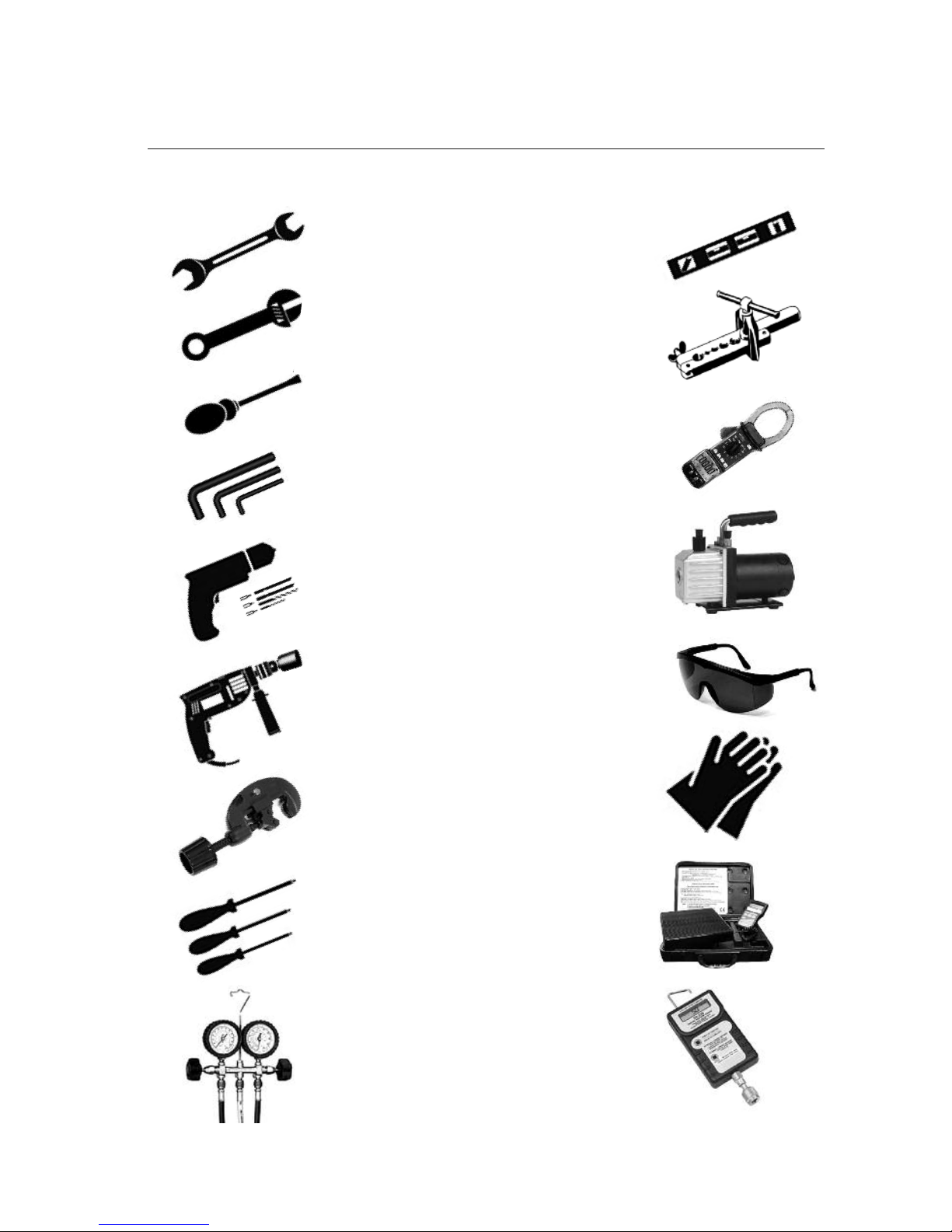
• Standard Wrench
• Adjustable/Crescent Wrench
• Torque Wrench
• Hex Keys or Allen Wrenches
• Drill & Drill Bits
• Hole Saw
• Pipe Cutter
• Screw drivers (Phillips & Flat blade)
• Manifold and Gauges
• Level
• R410A Flaring Tool
• Clamp on Amp Meter
• Vacuum Pump
• Safety Glasses
• Work Gloves
• Refrigerant Scale
• Micron Gauge
SUGGESTED TOOLS
6
7
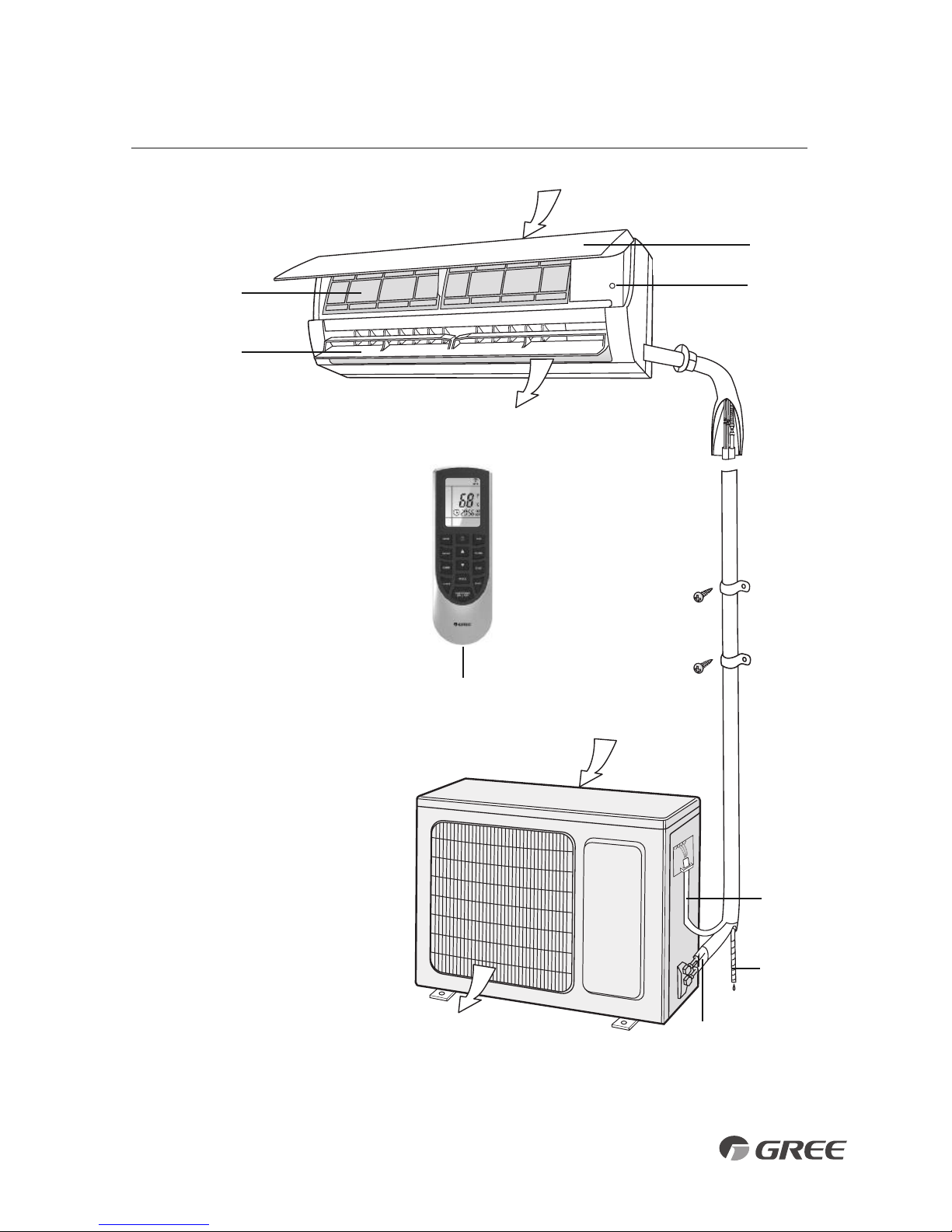
PART NAMES
Indoor unit
Part Name
1. Front Panel
2. Aux. Button
3. Filter
4. Horizontal Louver
5. Remote Controller
6. Inter-Connection Wire
7. Drain Hose
8. Refrigerant Lines
Outdoor unit
5
Air outlet
Air inlet
Air inlet
Air outlet
3
4
1
2
6
7
8
8
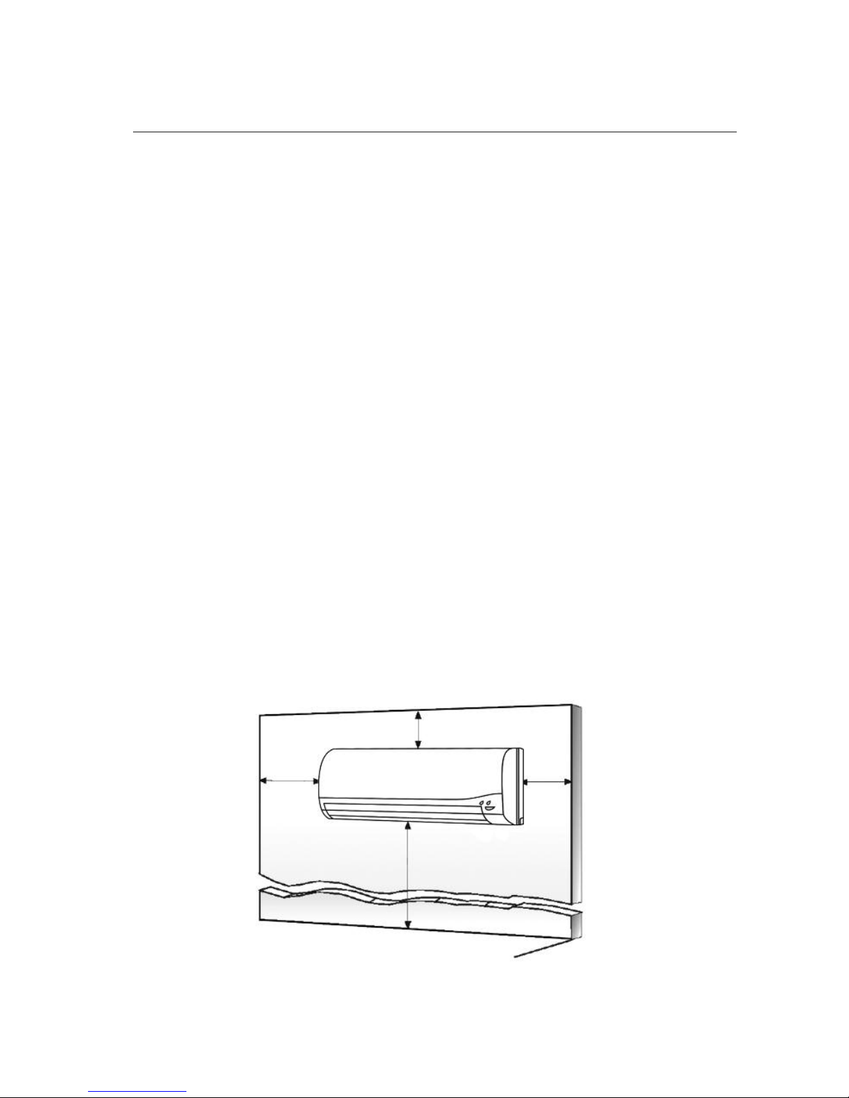
INSTALLATION SITE INSTRUCTIONS
Indoor Unit
Select a site that allows for the following:
1. Ensure the installation complies with the installation minimum dimensions (defined below)
and meets the minimum and maximum connecting piping length and maximum change in
elevation as defined in the System Requirements section.
2.
Air inlet and outlet will be clear of obstructions, ensuring proper airflow throughout the room.
3. Condensate can be easily and safely drained.
4. All connections can be easily made to outdoor unit.
5. Indoor unit is out of reach of children.
6.
A mounting wall strong enough to withstand four times the full weight and vibration of the unit.
7. Filter can be easily accessed for cleaning.
8. Leave enough free space to allow access for routine maintenance.
9. Install at least 10 ft. (3 m) away from the antenna of TV set or radio. Operation of the air
conditioner may interfere with radio or TV reception in areas where reception is weak.
An amplifier may be required for the affected device.
10. Do not install in a laundry room or by a swimming pool due to the corrosive environment.
Minimum Indoor clearances
6 in
(0.15m)
6 in
(0.15m)
6 ft (1.8m)
6 in (0.15m)
Ceiling
Floor
9
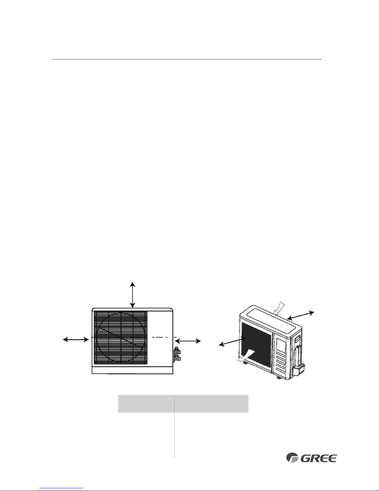
Outdoor Unit
Minimum Distances
in (mm)
A 20 (500)
B 12 (305)
C 20 (500)
D 24 (610)
E 12 (305)
Air inlet
Air outlet
INSTALLATION SITE INSTRUCTIONS
Outdoor Unit
Select a site that allows for the following:
1.
Outdoor location meets all minimum installation clearances defined below.
2.
Sound from outdoor unit will not annoy neighbors.
3.
All connections can be easily made to indoor unit.
4.
Air inlet and outlet will be clear of obstructions to ensure proper airflow.
5.
Wall or roof is strong enough to withstand the full weight and vibration of the outdoor
unit (for wall or roof installation only).
6.
Outdoor unit is out of reach of children and does not obstruct walkways.
7.
Outdoor unit is not exposed to direct sunlight, excessive dust or strong wind.
8. Condensate water can drain freely during heating
9.
Maintenance and repairs can be easily performed on the outdoor unit.
10.
Ensure the installation complies with the minimum and maximum connecting piping
length and maximum change in elevation as defined in the System Requirements section.
Minimum Outdoor Clearances
A
B
C D
E
 Loading...