

Gree GWH09MA-K3NNA3F, GWH09MA-K3NNA3E, GWH09MA-K3NNC5A, GWH09MA-K3NNC8A, (Refrigerant R410A) Service Manual

GREE ELECTRIC APPLIANCES INC.OF ZHUHAI
Service Manual
MODEL:
GWH09MA-K3NNA3F
GWH09MA-K3NNA3E
GWH09MA-K3NNC5A
GWH09MA-K3NNC8A
(Refrigera nt R410A)

Table of Contents
Summary and features..................................................................................
Part 1 Safety Precautions
..........................................................................................
Part 2 Specifications.....................................................................................................
2.1 Unit Specifications..................................................................................................
2.2 Capacity Variation Ratio According toTemperature..............................................
2.3 Operation Data....................................................................................................
Part 3 Construction Views
3.1 Indoor Unit ..........................................................................................................
3.2 Outdoor Unit .......................................................................................................
....................................................................................
Part 4 Refrigerant System Diagram
..................................................................
...
...
....
...
...
...
1
2
3
3
9
9
10
10
10
11
Part 5 Schematic Diagram.....................................................................................
5.1
5.1 Electrical Data
5.2 Electrical Wiring...........................................................................................
5.2 Printed Circuit Board...........................................................................................
Part 6 Function and Control
6.1 Remote Control Operations.................................................................................
6.2 Description of Each Control Operation................................................................
Part 7 Installation Manual
7.1 Notices for installation.........................................................................................
7.2 Installation diagram............................................................................
7.3 Install indoor unit.................................................................................................
7.4 Install Outdoor Unit..............................................................................................
7.5 Install of Quick Connector...................................................................................
7.6 Check after Installation and Operation Test........................................................
7.7 Installation and Maintenance of Healthy Filter....................................................
.................................................................................................
...........
..................................................................................
.......................................................................................
....................
...
...
...
...
...
..
...
...
...
...
...
...
12
12
12
16
18
18
24
28
28
30
31
33
35
37
38

Part 9 Troubleshooting..........................................................................................
...
9.1 ..............................................................................................
...
Part 8 Exploded Views and Parts List
.........................................................
...
8.1 Indoor Unit.......................................................................................................
...
Part10 Removal Procedure..................................................................................
...
Table of Contents
39
39
47
53
53
54
58
70
58
66
10.1 Removal Procedure of Indoor Unit...................................................................
10.2 Removal Procedure of Outdoor Unit................................................................
10.3 Removal Procedure of Outdoor Unit(Quick Connector)...................................
9.2 How to Check simply the main part.................................................................
...
8.2 Outdoor Unit....................................................................................................
...
Mlafunction Code
1
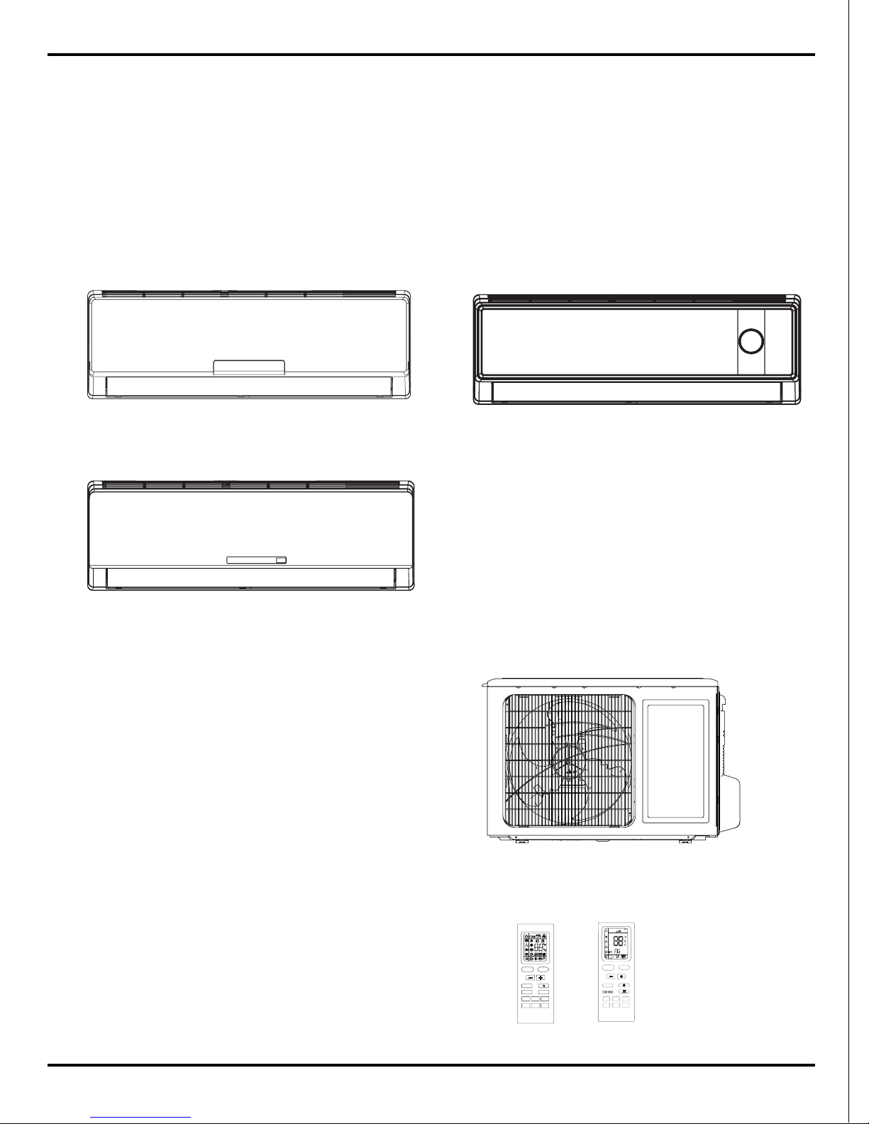
Summary and features
Summary and features
GWH09MA-K3NNA3F/I
GWH09MA-K3NNA3E/I
Indoor Unit
GWH09MA-K3NNC5A/I
Outdoor Unit
GWH09MA-K3NNA3A/O
GWH09MA-K3NNA3E/O
GWH09MA-K3NNA3F/O
GWH09MA-K3NNC8A/I
ONOFF/
MODE
FAN
CLOCK TIMERON
X-FAN TEMP
TIMEROFF
TURBO SLEEP LIGHT
FAN
AUTO
OPER
HEALTH
AIR
FILTER
TURBO
ON/OFF
X-FAN
HOUR
HUMIDITY
ON/OFF
MODE
FAN
X-FAN
TURBO
TEMP
TIMER
SLEEP
LIGHT
Remote control window
YB1FA
YB1F4
2
1.Safety Precautions
Safety Precautions
Caution
Warning
Warning
Caution
could result in
personal injury
or death.
Incorrect handling
result in
injury, or damage to product
or property.
Incorrect handling
may
minor
Recognize the following safety information:
Installing, starting up, and servicing air conditioner can be
hazardous due to system pressure, electrical components, and
equipment location, etc.
Only trained, qualified installers and service personnel are
allowed to install, start-up, and service this equipment.
Untrained personnel can perform basic maintenance functions
such as cleaning coils. All other operations should be
performed by trained service personnel.
When handling the equipment, observe precautions in the
manual and on tags, stickers, and labels attached to the
equipment. Follow all safety codes. Wear safety glasses and
work gloves. Keep quenching cloth and fire extinguisher nearby
when brazing.
Read the instructions thoroughly and follow all warnings or
cautions in literature and attached to the unit. Consult local
building codes and current editions of national as well as local
electrical codes.
All electric work must be performed by a licensed technician
according to local regulations and the instructions given in this
manual.
Never supply power to the unit unless all wiring and tubing
are completed, reconnected and checked.
This system adopts highly dangerous electrical voltage.
Incorrect connection or inadequate grounding can cause
personal injury or death. Stick to the wiring diagram and all
the instructions when wiring.
Have the unit adequately grounded in accordance with
local electrical codes.
Have all wiring connected tightly. Loose connection may
lead to overheating and a possible fire hazard.
All installation or repair work shall be performed by your dealer
or a specialized subcontractor as there is the risk of fire, electric
shock, explosion or injury.
Make sure the ceiling/wall is strong enough to bear the
weight of the unit.
Make sure the noise of the outdoor unit does not disturb
neighbors.
Properly insulate any tubing running inside the room to
prevent the water from damaging the wall.
Make sure the outdoor unit is installed on a stable, level
surface with no accumulation of snow, leaves, or trash
beside.
Follow all the installation instructions to minimize the risk
of damage from earthquakes, typhoons or strong winds.
Avoid contact between refrigerant and fire as it generates
poisonous gas.
Apply specified refrigerant only. Never have it mixed with
any other refrigerant. Never have air remain in the
refrigerant line as it may lead to rupture and other hazards.
Make sure no refrigerant gas is leaking out when
installation is completed.
Should there be refrigerant leakage, the density of
refrigerant in the air shall in no way exceed its limited
value, or it may lead to explosion.
Before installing, modifying, or servicing system, main
electrical disconnect switch must be in the OFF position.
There may be more than 1 disconnect switch. Lock out and
tag switch with a suitable warning label.
Keep your fingers and clothing away from any moving
parts.
Clear the site after installation. Make sure no foreign
objects are left in the unit.
Always ensure effective grounding for the unit.
Never install the unit in a place where a combustible gas
might leak, or it may lead to fire or explosion.
Make a proper provision against noise when the unit is
installed at a telecommunication center or hospital.
Provide an electric leak breaker when it is installed in a
watery place.
Never wash the unit with water.
Handle unit transportation with care. The unit should not be
carried by only one person if it is more than 20kg.
Never touch the heat exchanger fins with bare hands.
Never touch the compressor or refrigerant piping without
wearing glove.
Do not have the unit operate without air filter.
Should any emergency occur, stop the unit and disconnect
the power immediately.
3
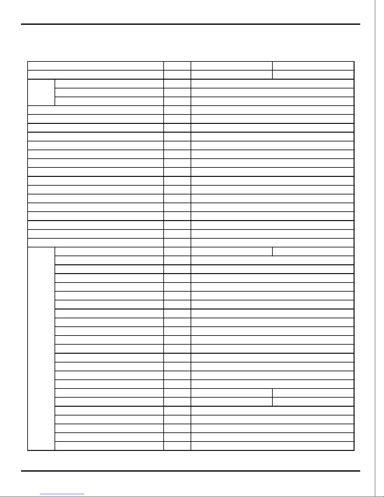
2.Specifications
2.1 Unit Specifications
Specifications
GWH09MA-K3NNC8A GWH09MA-K3NNC5A
CA19200010 CA17900040
Rated Voltage
V
~
Rated Frequency Hz
Phases
W
W
W
W
A
A
W
A
m
3
/h
L/h
W/W
W/W
W/W
W/W
m
2
Model of indoor unit GWH09MA-K3NNC8A/I GWH09MA-K3NNC5A/I
Fan Type
Diameter Length(DXL) mm
Fan Motor Cooling Speed(SH/H/M/L/SL) r/min
Fan Motor Heating Speed(SH/H/M/L/SL) r/min
Output of Fan Motor W
Fan Motor RLA A
Fan Motor Capacitor μF
Input of Heater W
Evaporator Form
Pipe Diameter mm
Row-fin Gap mm
Coil Length (LXDXW) mm
Swing Motor Model
Output of Swing Motor W
Fuse A
Sound Pressure Level (SH/H/M/L/SL) dB (A) 39/36/33/30/- 39/36/33/30/-
Sound Power Level (SH/H/M/L/SL) dB (A) 50/48/45/42/- 50/48/45/42/-
Dimension (WXHXD) mm
Dimension of Carton Box (L/W/H) mm
Dimension of Package(L/W/H) mm
Net Weight kg
Gross Weight kg
Model
Product Code
Power
Supply
Power Supply Mode
Cooling Capacity
Heating Capacity
Cooling Power Input
Heating Power Input
Cooling Power Current
Heating Power Current
Rated Input
Rated Current
Air Flow Volume(SH/H/M/L/SL)
Dehumidifying Volume
EER
Indoor
Unit
COP
SEER
HSPF
Application Area
220-240
50
1
Indoor
2600
2800
809
775
3.7
3.5
1120/1020
5/4.5
500/-/-/-
0.8
3.21
3.61
/
/
12-18
Cross-flow
Φ85X596
1260/1050/920/730/-
1320/1200/1100/950/-
10
0.1
1
/
Aluminum Fin-copper Tube
Φ7
2-1.5
581X25.4X264
MP24AA
870X248X355
9
12
1.5
PCB 3.15A
790X265X177
867X245X340
4
The above data is subject to change without notice. Please refer to the nameplate of the unit.
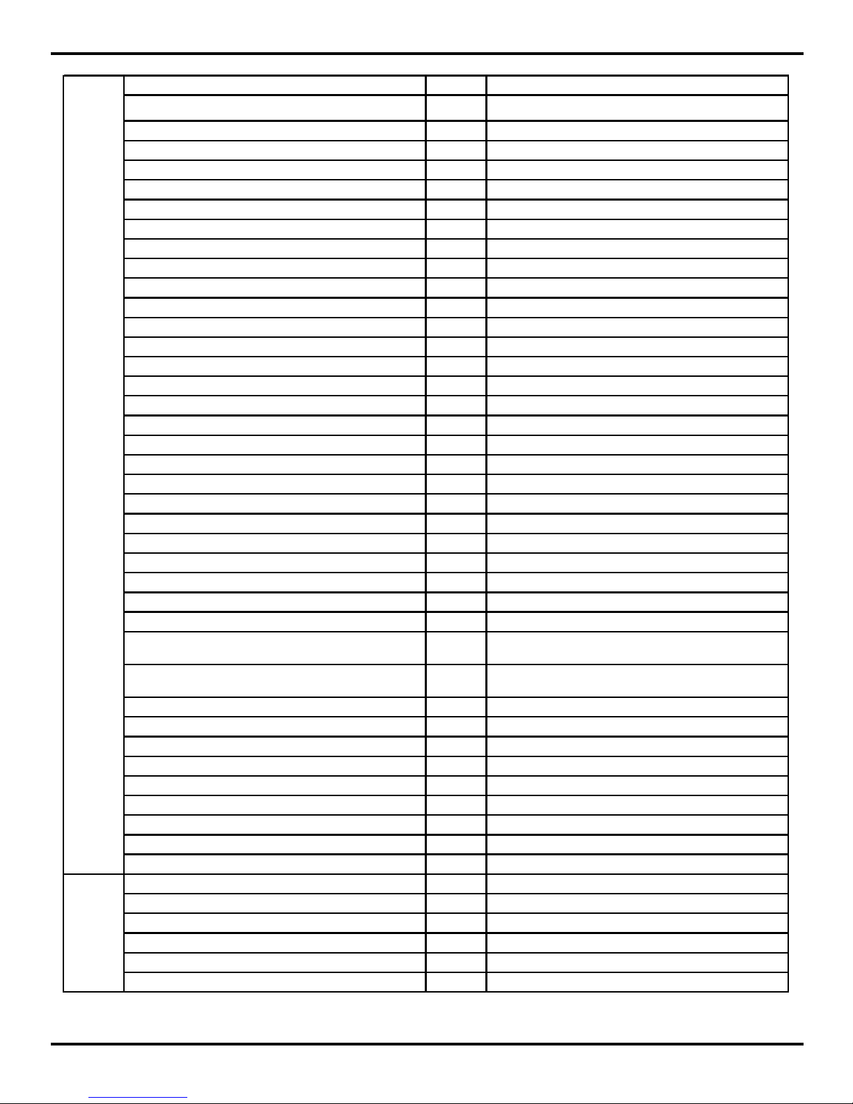
Specifications
Model of Outdoor Unit GWH09MA-K3NNA3A/O
Compressor Manufacturer/Trademark ZHUHAI LANDA COMPRESSOR CO. LTD. /GREE
Compressor Model QXA-B102uC130
Compressor Oil PVE(DN HERMITIC FVC 68D)
Compressor Type Rotary
L.R.A. A 18
Compressor RLA A 3.9
Compressor Power Input W 858
Overload Protector B210-150-241H
Throttling Method Capillary
Operation Temp
℃
16~30
Ambient Temp (Cooling)
℃
18~43
Ambient Temp (Heating)
℃
-7~24
Condenser Form Aluminum Fin-copper Tube
Pipe Diameter mm Φ7
Rows-fin Gap mm
1-1.4
Coil Length (LXDXW) mm 741X495.3X12.7
Fan Motor Speed rpm 850
Output of Fan Motor W 30
Fan Motor RLA A 0.23
Fan Motor Capacitor μF2
Air Flow Volume of Outdoor Unit
m
3
/h
1800
Fan Type Axial-flow
Fan Diameter mm Φ400
Defrosting Method Automatic Defrosting
Climate Type T1
Isolation I
Moisture Protection IP24
Permissible Excessive Operating Pressure for the
Discharge Side
MPa 3.8
Permissible Excessive Operating Pressure for the
Suction Side
MPa 1.2
Sound Pressure Level (H/M/L) dB (A) 50/-/-
Sound Power Level (H/M/L) dB (A) 60/-/-
Dimension (WXHXD) mm 848X540X320
Dimension of Carton Box (L/W /H) mm 875X357X565
Dimension of Package(L/W/H) mm 878X360X580
Net Weight kg 26
Gross Weight kg 30
Refrigerant R410A
Refrigerant Charge kg 0.75
Length m 4
Gas Additional Charge g/m 20
Outer Diameter Liquid Pipe mm Φ6
Outer Diameter Gas Pipe mm Φ9.52
Max Distance Height m 10
Max Distance Length m 20
Outdoor
Unit
Connectio
n Pipe
5
Specifications
GWH09MA-K3NNA3F
CA17100680
Rated Voltage
V
~
220-240
Rated Frequency Hz 50
Phases 1
Indoor
W 2600
W 2800
W 809
W 775
A3.59
A3.44
W 1120
A4.97
m
3
/h
500/-/-/-/-
L/h 0.8
W/W 3.21
W/W 3.61
W/W /
W/W /
m
2
12-18
Model of indoor unit GWH09MA-K3NNA3F/I
Fan Type Cross-flow
Diameter Length(DXL) mm Φ85X596
Fan Motor Cooling Speed(SH/H/M/L/SL) r/min 1260/1050/920/730/-
Fan Motor Heating Speed(SH/H/M/L/SL) r/min 1320/1200/1100/950/-
Output of Fan Motor W 10
Fan Motor RLA A 0.13
Fan Motor Capacitor μF 1
Input of Heater W /
Evaporator Form Aluminum Fin-copper Tube
Pipe Diameter mm Φ7
Row-fin Gap mm 2-1.5
Coil Length (LXDXW) mm 589X25.4X266.7
Swing Motor Model MP24AA
Output of Swing Motor W 1.5W
Fuse A PCB 3.15A
Sound Pressure Level (SH/H/M/L/SL) dB (A) 40/37/35/32/-
Sound Power Level (SH/H/M/L/SL) dB (A) 49/47/45/42/-
Dimension (WXHXD) mm 790X265X170
Dimension of Carton Box (L/W/H) mm 870X248X355
Dimension of Package(L/W/H) mm 873X251X370
Net Weight kg 9
Gross Weight kg 12
Model
Product Code
Power
Supply
Power Supply Mode
Cooling Capacity
Heating Capacity
Cooling Power Input
Heating Power Input
Cooling Power Current
Heating Power Current
Rated Input
Rated Current
Air Flow Volume(SH/H/M/L/SL)
Dehumidifying Volume
EER
Indoor
Unit
COP
SEER
HSPF
Application Area
6
Specifications
Model of Outdoor Unit GWH09MA-K3NNA3F/O
Compressor Manufacturer/Trademark GREE
Compressor Model QXA-B102uC130
Compressor Oil PVE(DN HERMITIC FVC 68D)
Compressor Type Rotary
L.R.A. A 18
Compressor RLA A 4±5%
Compressor Power Input W 858±5%
Overload Protector B210-150-241H
Throttling Method Capillary
Operation Temp
℃
16~30
Ambient Temp (Cooling)
℃
18~43
Ambient Temp (Heating)
℃
-7~24
Condenser Form Aluminum Fin-copper Tube
Pipe Diameter mm Φ7
Rows-fin Gap mm 1-1.4
Coil Length (LXDXW) mm 780.45X12.7X495.3
Fan Motor Speed rpm 800
Output of Fan Motor W 30
Fan Motor RLA A 0.37
Fan Motor Capacitor μF 2
Air Flow Volume of Outdoor Unit
m
3
/h
1800
Fan Type Cross-flow
Fan Diameter mm 400
Defrosting Method Automatic Defrosting
Climate Type T1
Isolation I
Moisture Protection IP24
Permissible Excessive Operating Pressure for the
Discharge Side
MPa 3.8
Permissible Excessive Operating Pressure for the
Suction Side
MPa 1.2
Sound Pressure Level (H/M/L) dB (A) 50
Sound Power Level (H/M/L) dB (A) 60
Dimension (WXHXD) mm 848X540X320
Dimension of Carton Box (L/W/H) mm 878X360X580
Dimension of Package(L/W/H) mm 881X363X605
Net Weight kg 29
Gross Weight kg 33
Refrigerant R410A
Refrigerant Charge kg 0.75
Length m 4
Gas Additional Charge g/m 20
Outer Diameter Liquid Pipe mm Φ6
Outer Diameter Gas Pipe mm Φ9.52
Max Distance Height m 10
Max Distance Length m 15
Outdoor
Unit
Connectio
n Pipe
The above data is subject to change without notice. Please refer to the nameplate of the unit.
7
Specifications
GWH09MA-K3NNA3E
CA17100800
Rated Voltage
V
~
220-240
Rated Frequency Hz 50
Phases 1
Indoor
W 2680
W 2880
W 834
W 797
A3.70
A3.54
W 1120
A4.97
m
3
/h
500 /-/-/-/-
L/h 0.8
W/W 3.21
W/W 3.61
W/W /
W/W /
m
2
12-18
Model of indoor unit GWH09MA-K3NNA3E/I
Fan Type Cross-flow
Diameter Length(DXL) mm Φ85X596
Fan Motor Cooling Speed(SH/H/M/L/SL) r/min 1260/1050/920/730/-
Fan Motor Heating Speed(SH/H/M/L/SL) r/min 1320/1200/1100/950/-
Output of Fan Motor W 10
Fan Motor RLA A 0.13
Fan Motor Capacitor μF 1
Input of Heater W /
Evaporator Form Aluminum Fin-copper Tube
Pipe Diameter mm Φ7
Row-fin Gap mm 2-1.5
Coil Length (LXDXW) mm 589X25.4X266.7
Swing Motor Model MP24AA
Output of Swing Motor W 1.5W
Fuse A PCB 3.15A Transformer 0.2A
Sound Pressure Level(SH/H/M/L/SL) dB (A) 39/37/35/32/-
Sound Power Level(SH/H/M/L/SL) dB (A) 49/47/45/42/-
Dimension (WXHXD) mm 790X265X170
Dimension of Carton Box (L/W/H) mm 1017X325X352
Dimension of Package(L/W/H) mm 1020X328X367
Net Weight kg 13.5
Gross Weight kg 18
Model
Product Code
Power
Supply
Power Supply Mode
Cooling Capacity
Heating Capacity
Cooling Power Input
Heating Power Input
Cooling Power Current
Heating Power Current
Rated Input
Rated Current
Air Flow Volume(SH/H/M/L/SL)
Dehumidifying Volume
EER
Indoor
Unit
COP
SEER
HSPF
Application Area
8
Specifications
The above data is subject to change without notice. Please refer to the nameplate of the unit.
Model of Outdoor Unit GWH09MA-K3NNA3E/O
Compressor Manufacturer/Trademark ZHUHAI LANDA COMPRESSOR CO. LTD. /GREE
Compressor Model QXA-B102uC130
Compres sor Oil PVE(DN HERMITIC FVC 68D)
Compressor Type Rotary
L.R.A. A 18
Compres sor RLA A 4±5%
Compressor Power Input W 858±5%
Overload Protector B210-150-241H
Throttling Method Capillary
Operation Temp
℃
16~30
Ambient Temp (Cooling)
℃
18~43
Ambient Temp (Heating)
℃
-7~24
Condenser Form Aluminum Fin-copper Tube
Pipe Diameter mm Φ7
Rows -fin Gap m m 1-1.4
Coil Length (LXDXW) mm 780.45X12.7X495.3
Fan Motor Speed rpm 800
Output of Fan Motor W 30
Fan Motor RLA A 0.37
Fan Motor Capacitor μF 2
Air Flow Volume of Outdoor Unit
m
3
/h
1800
Fan Type Cross -flow
Fan Diameter mm 400
Defrosting Method Automatic Defrosting
Climate Type T1
Isolation I
Moisture Protection IP24
Permissible Excessive Operating Pressure for the
Discharge Side
MPa 3 .8
Permissible Excessive Operating Pressure for the
Suction Side
MPa 1 .2
Sound Pressure Level (H/M/L) dB (A) 50
Sound Power Level (H/M/L) dB (A) 60
Dimension (WXHXD) mm 848X540X320
Dimension of Carton Box (L/W/H) mm 878X360X580
Dimension of Package(L/W/H) mm 881X363X595
Net Weight kg 29
Gross Weight kg 33
Refrigerant R410A
Refrigerant Charge kg 0.70
Length m 5
Gas Additional Charge g/m /
Outer Diameter Liquid Pipe mm /
Outer Diameter Gas Pipe mm /
Max Distance Height m /
Max Distance Length m /
Outdoo r
Unit
Connecti
on Pipe
9
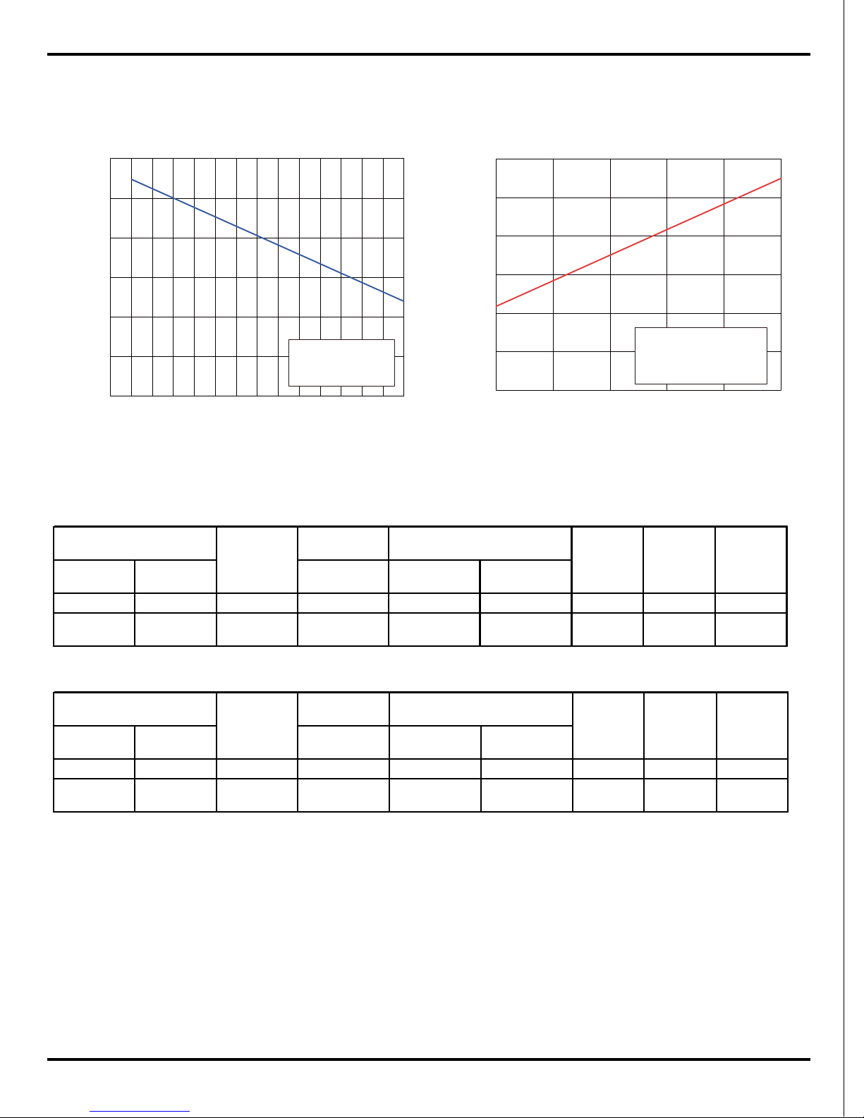
2.2 Capacity Variation Ratio According to Temperature
Specifications
HeatingCooling
50
70
60
80
90
100
110
32
34
36
38
40
42
44
46
Capacity ratio(%)
0
20
40
60
80
100
120
-15
-10
-5
0
5
10
Capacity ratio(%)
Outdoor temp.(℃)Outdoor temp.(℃)
Condition Cooling
Indoor:DB27℃ WB19℃
ndoor air flow: Super High
Pipe length:5m or 4m
Condition Heating
Indoor:DB20℃
Indoor air flow: Super High
Pipe length:5m or 4m
Cooling
Heating
NOTES :
(1) Measure surface temperature of heat exchanger pipe around center of heat exchanger path U
bent. (Thermistor themometer)
(2) Connecting piping condition : 5 m or 4m
2.3 Operation Dat
Standard
pressure
Indoor Outdoor P (MPa) T1 (°C) T2 (°C)
27/19 35/24
9K 0.99~1.19 10.2 to 13.4 79.6 to 37.9
1260
830±20 /
27/19 35/24 12K 0.48~0.56
in:8 to 11
out:11 to 14
in:75 to 85
out:37 to 43
1260 850 /
Compresso
r revolution
(rps)
Model name
Temperature condition (℃)
Heat exchanger pipe temp
Indoor fan
mode
Outdoor fan
mode
Standard
pressure
Indoor Outdoor P (MPa) T1 (°C) T2 (°C)
20/- 7/6
9K 2.38~2.58 80.1 to 35.5 7.5 to 5.3
1320
830±20 /
20/- 7/6 12K 1.55~1.75
in:75 to 85
out:37 to 43
in:1 to 3
out:2 to 5
1280 850 /
Compresso
r revolution
(rps)
Model name
Temperature condition (℃)
Heat exchanger pipe temp
Indoor fan
mode
Outdoor fan
mode
P: gas valve outlet pressure
T1: outlet tube temperature of evaporator
T2: outlet tube temperature of condenser
a
10
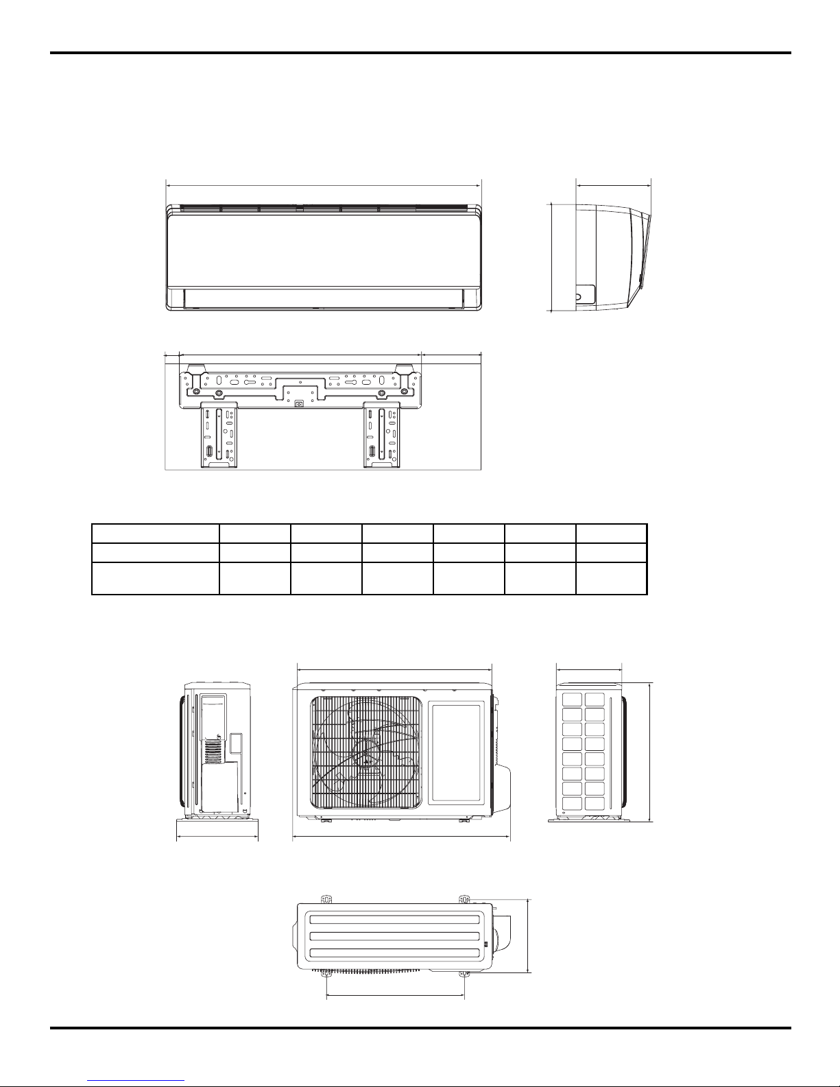
3. Construction Views
3.1 Indoor Unit
Constrction views
W
H
D
RQ
3.2 Outdoor Unit
848
540
320
762
286
257
540
Unit:mm
S
Model W H D Q R S
09K 790 265 177 35 605 150
GWH09MA-K3NNA3F
GWH09MA-K3NNA3E
790 265 170 35 605 150
11
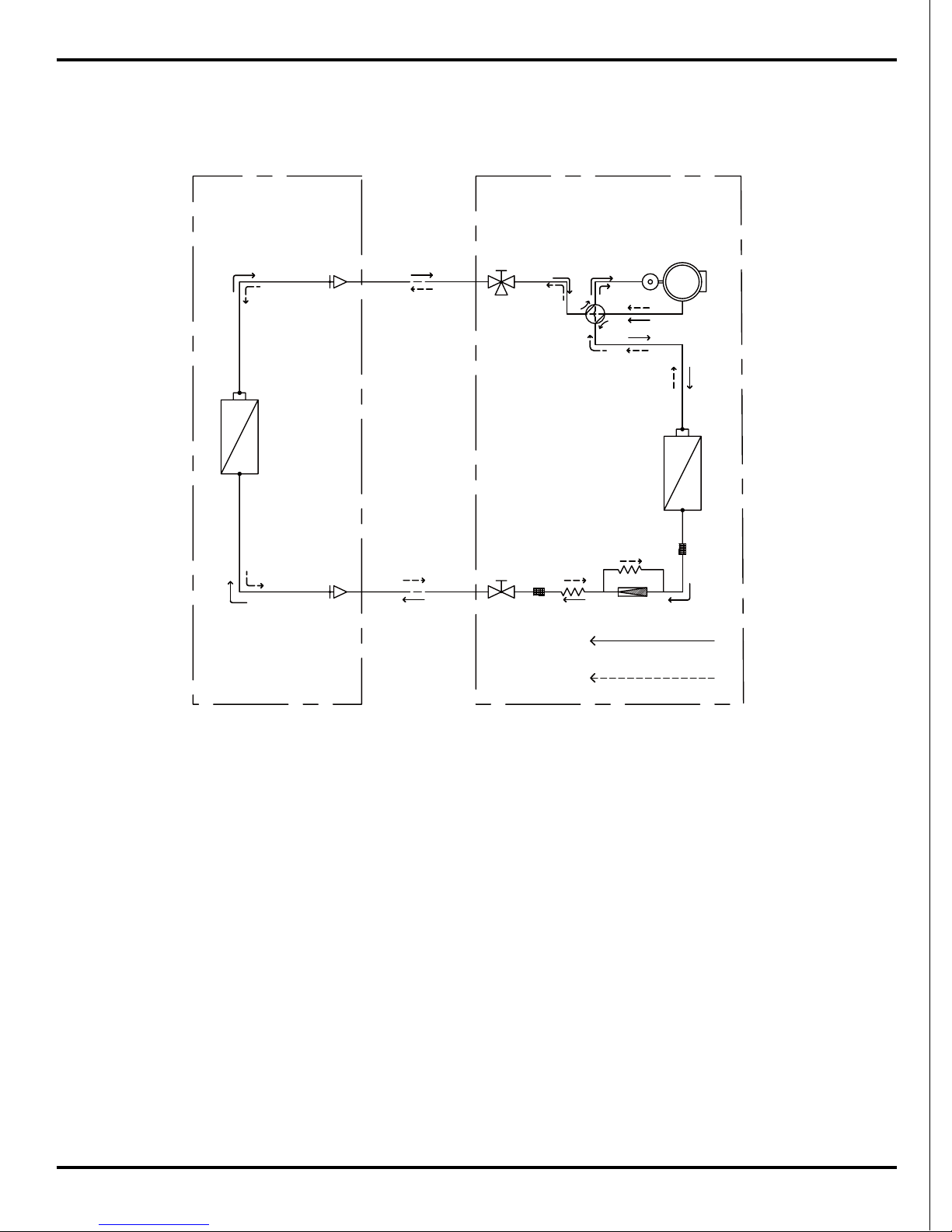
4. Refrigerant System Diagram
Refrigerant System Diagram
Refrigerant pipe diameter
Liquid : 1/4" (6 mm)
Gas : 3/8" (9.52 mm)
Cooling cycle
Indoor unit
Outdoor unit
Narrow tube
Wide tube
Capillary
tube
Heat exchanger
Heat exchanger
Compressor
䯔
Capillary
tube
Heating cycle
4-way valve
Accumlator
Strainer
Strainer
Wide tube
service
valve
Narrow
tube
service
valve
12
5. Schematic Diagram
5.1 Electrical Dat
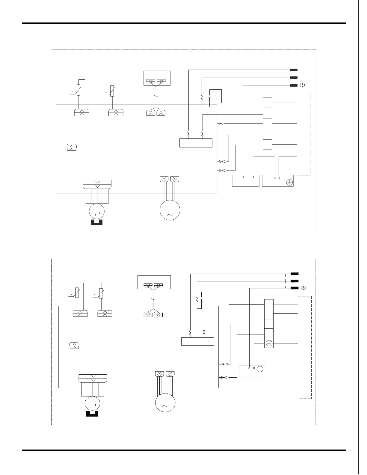
5.2 Electrical wiring
Indoor Unit
Schematic Diagram
GWH09MA-K3NNC5A/I GWH09MA-K3NNC8A/I
TR_IN
TR_OUT
TC
MOTOR
STEPPING
M2
SWING-UD
PGF
PG
M1
N
2
XT1
YEGN(GN)
BN(BK)
BU(WH)
BU
BK
POWER
CONN WIRE
4
OUTDOOR UNIT
N1
W2BK
W1BU
ROOM
DISP1
AP1
ROOM
DISPLAY
FAN MOTOR
OFAN
EVAPORATOR
W5OG
W4VT
AP2
PRINTED CIRCUIT BOARD
TUBE
RT2
PIPE
TEM.SENSOR
RT1
TEM.SENSOR
TRANSFORMER
YEGN
5
4V
VT
OG
YEGN
W3
DISP2
K1
AC-L
COMP
CAP
JUMP
0
0
II
N
L
I
Symbol Color symbol Symbol Color symbol
WH WHITE BN BROWN
YE YELLOW BU BLUE
RD RED BK BLACK
YEGN YELLOW GREEN VT VIOLET
OG ORANGE PROTECTIVE EARTH
SAT OVERLOAD COMP COMPRESSOR
GN GREEN
a
13
GWH09MA-K3NNA3F/I
GWH09MA-K3NNA3E/I
Schematic Diagram
MOTOR
STEPPING
M2
SWING-UD
PGF
PG
M1
N
2
XT1
YEGN(GN)
BN(BK)
BU(WH)
BU
BK
POWER
CONN WIRE
4
OUTDOOR UNIT
N1
W2BK
W1BU
ROOM
DISP1
AP1
ROOM
DISPLAY
FAN MOTOR
OFAN
EVAPORATOR
W5OG
W4VT
AP2
PRINTED CIRCUIT BOARD
TUBE
RT2
PIPE
TEM.SENSOR
RT1
TEM.SENSOR
YEGN
5
4V
VT
OG
YEGN
W3
DISP2
K1
AC-L
COMP
CAP
JUMP
0
0
N
L
L
N
DISP1
AP1
DISPLAY
DISP2
BN
BN
3
YEGN
EARTH-PLATE
YEGN
JUMP
CAP
COMP
AC-L
K1
OG
VT
4V
5
TEM.SENSOR
RT1
TEM.SENSOR
PIPE
RT2
TUBE
PRINTED CIRCUIT BOARD
AP2
VT
OG
EVAPORATOR
OFAN
ROOM
ROOM
BU
BK
N1
OUTDOOR UNIT
4
CONN WIRE
POWER
BK
BU
BU(WH)
BN(BK)
YEGN(GN)
XT1
2
N(1)
SWING-UD
M2
STEPPING
MOTOR
M1
FAN MOTOR
PGF
PG
L1
0
0
14
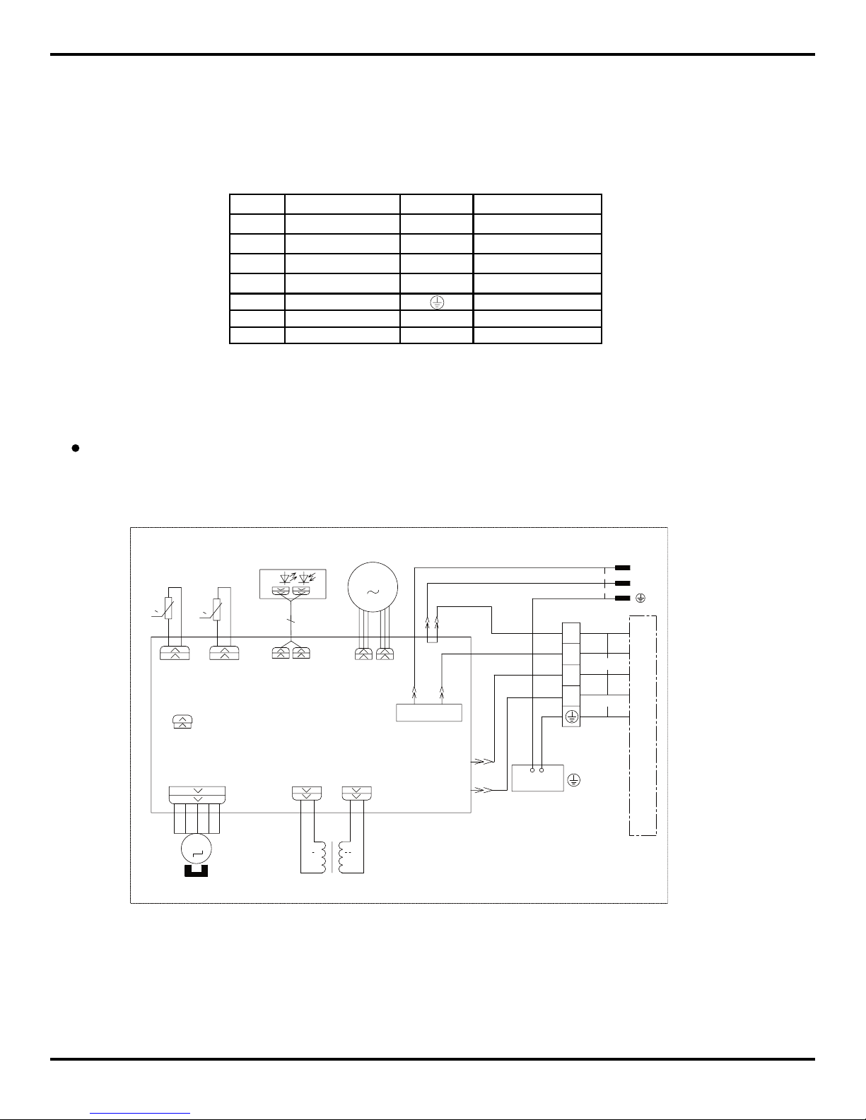
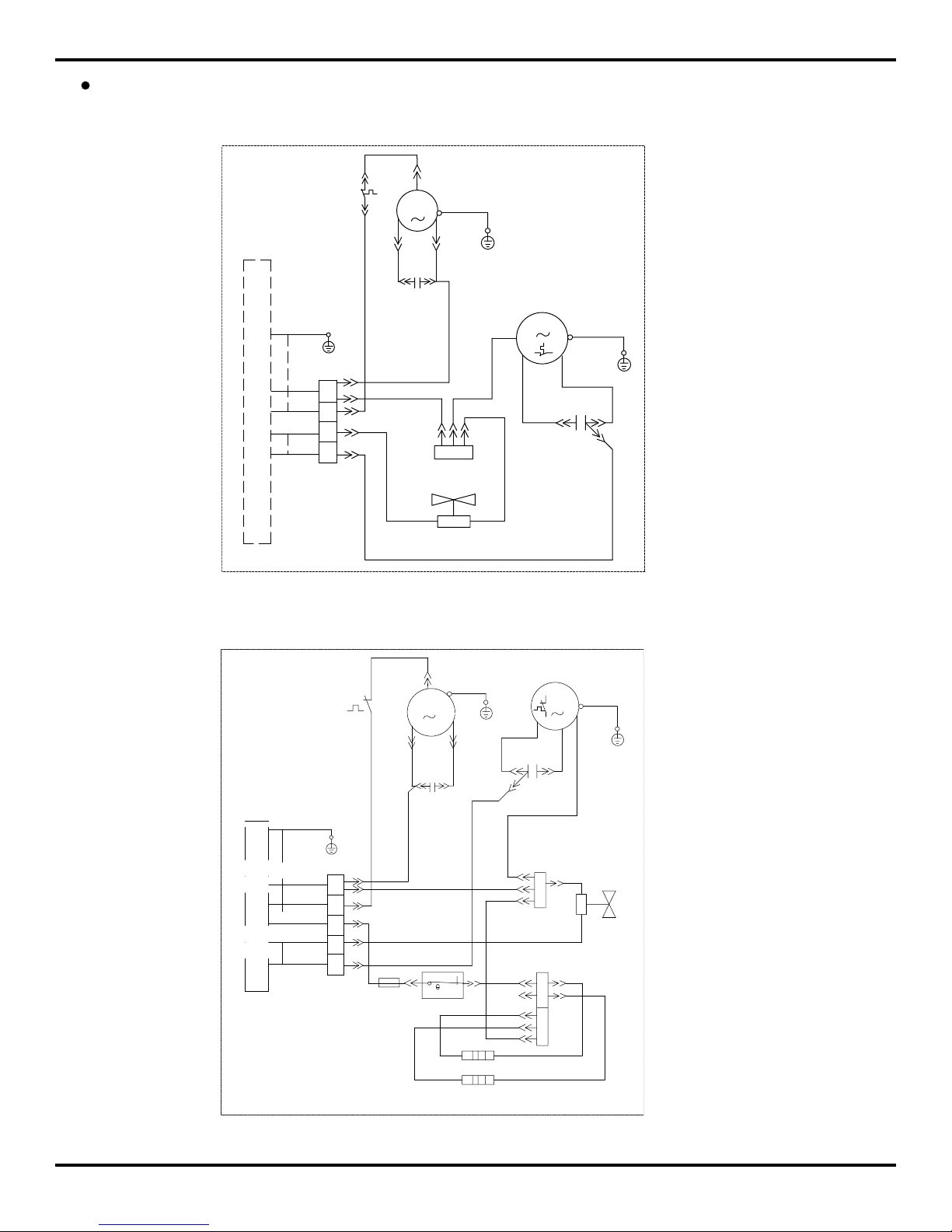
Outdoor Unit
Schematic Diagram
GWH09MA-K3NNA3A/O
GWH09MA-K3NNA3F/O
YEGN
BU
BN
RD
OG
INDOOR UNIT
BU
BU
OG
VT
BK
BU
YEGN
BK YE BU
YEGN
2
E
C2
E
E
E
R(M,V)
E
C1
SAT
4
5
C(T,U)
S(W,X)
COMP.
MOTOR
XT1
XT2
N(1)
YV
M1
COMP
MOTOR
FAN
INDOOR UNIT
BK
BN
RD
COMP.
C(T,U)
YE
BU
C1
S(W,X)
R(M,V)
C2
YEGN
BU
BK
OG
BU
BU
BK
VT
OG
BN
BN
C
H
L
BU
EH1
EH2
BN
GNYE
E
YEGN
E
E
BASE HEATER
COMP. HEATER
BOARD
TERMINAL
SAT
XT1
XT2
XT3
FUT
YV
FAN
MOTOR
M2
M1
1
2
ST1
5
N(1)
4
2
3
15
BK
BU
VT
OG
INDOOR
UNIT
~
~
X1
YEGN
E
E
YEGN
W7BU
C1
R<M>
W6BU
E
M1
M2
FAN
MOTOR
E
C
W2BK
RD
BN
BK
W5YE
S
12
W8YEGN
COMP.
XT
2
W4OG
1
C2
W3VT
1
2
W1BU
4-WAY VALVE
YV
E
SAT
W9
4
1
2
4
2
1
5
5
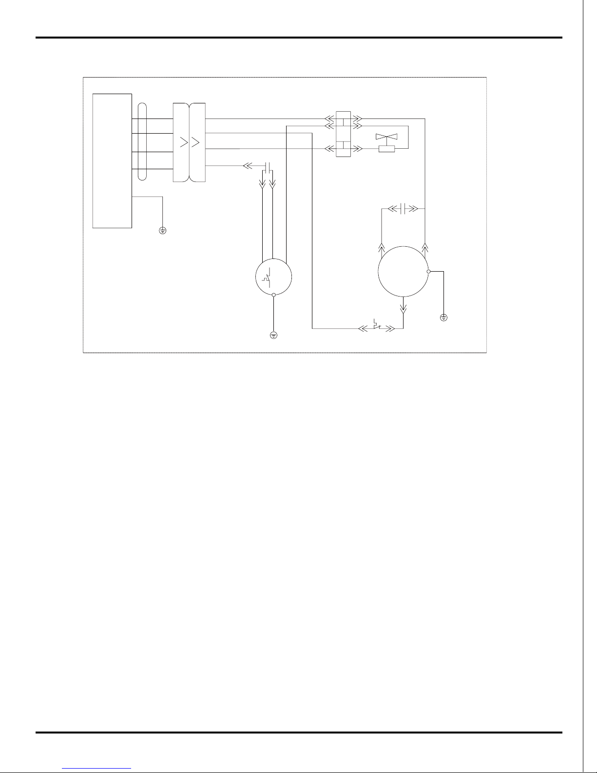
Schematic Diagram
GWH09MA-K3NNA3E/O
These circuit diagrams are subject to change without notice, please refer to the one supplied with the unit.
16
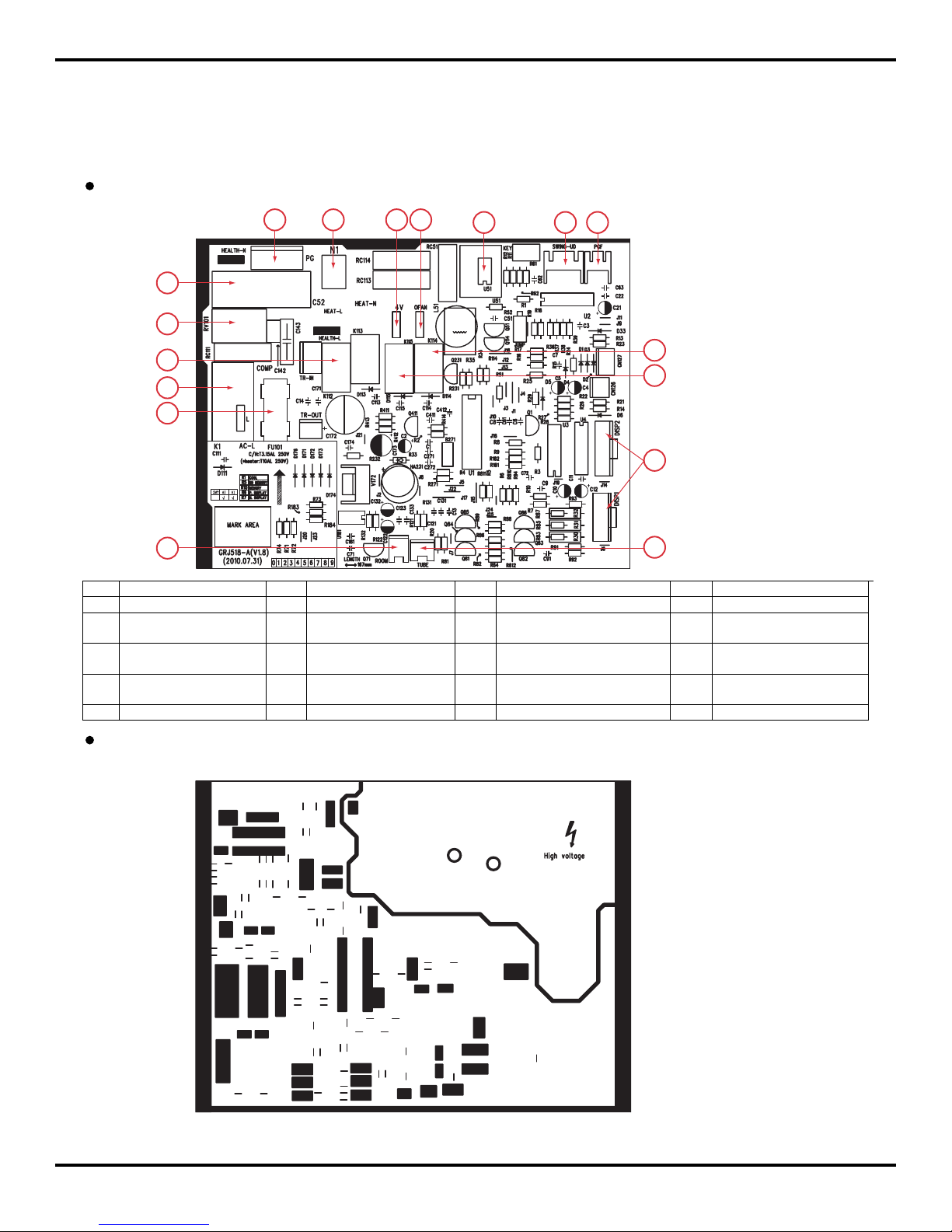
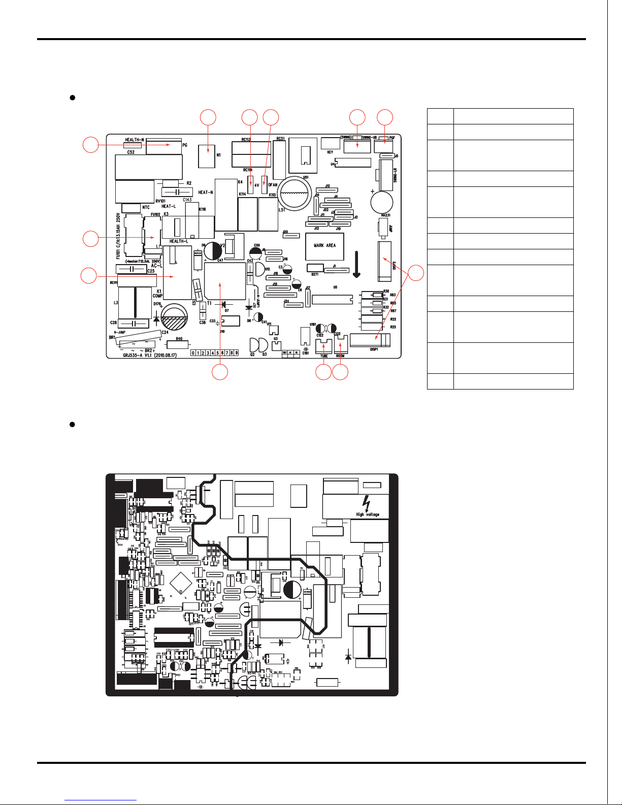
5.3 Printed Circuit Board
GWH09MA-K3NNC5A GWH09MA-K3NNC8A
TOP VIEW
BOTTOM VIEW
Schematic Diagram
2
3
4
5
6
7
8
9
10
11
12
13
14
15
16
17
1
NO. Name NO. Name NO. Name NO. Name
1 PG motor connector 2 Insert of neutral wire 3 Insert of 4-way valve 4 Insert of outdoor fan
5 Solid-state relay 6 Up & down swing
connector
7 PG motor feedback connector 8 Relay controlling fan
9 Relay for controlling
4-way valve
10 Connect dispaly1 & 2 11 Indoor tube temperature sensor
connector
12 Indoor ambient temperature
sensor connector
13 Protective tube 14 Compressor relay and live
wire connector
15 Relay controlling cold plasma 16 Piezoresistor
17 Fan capacitor
17
Schematic Diagram
TOP VIEW
BOTTOM VIEW
1
2
3
4
5
6
7
8
12
11
10
9
GWH09MA-K3NNA3E GWH09MA-K3NNA3F
NO. Name
1 Compressor connector
2 Live wire connector of
power supply
3 Indoor fan connector
4 Neutral wire connector of
power supply
5 4-way valve connector
6 Outdoor fan connector
7 Left & right swing connector
8 Indoor fan state feedback
connector
9 Display connector
10 Ambient temperature
sensor connector
11 Tube temperature sensor
connector
12 High frequency transformer
18
6. Function and Control
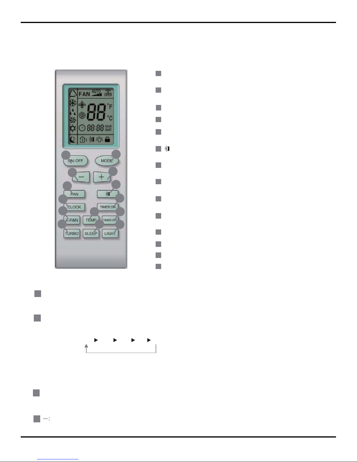
6.1 Remote Control Operations
Function and Control
2
8
9
10
3
4
11
12
7
6
13
14
5
1
Press it to start or stop operation
ON/OFF
1
MODE
Press it to select operation mode(AUTO/COOL/DRY/FAN/HEAT)
2
+
: Press it to increase temperature setting
3
-
:
Press it to decrease temperature setting
4
FAN
Press it to set fan speed
5
Press it to set swing angle
6
TIMER ON
Press it to set auto-on timer
7
TIMER OFF
Press it to set auto-off timer
8
CLOCK
Press it to set clock
9
10
TEMP
11
TURBO
12
SLEEP
13
Press it to turn on/off the light.
LIGHT
14
Press this button to start the unit operation .Press this button again to stop the unit operation.
ON/OFF :
MODE :
Each time you press this button,a mode is selected in a sequence that goes from AUTO,COOL,DRY, FAN,and HEAT
as the following:
AUTO
COO L
DRY
FAN HEAT
*
*Note:Only for models with heating
function.
+
:
Press this button to increase set temperature.Holding it down above 2 seconds
rapidly increases set temperature. In AUTO
Press this button to decrease
set temperature.Holding it down above 2 seconds rapidly decreases set temperature. In AUTO
.
1
2
3
4
After energization, AUTO mode is defaulted. In AUTO mode, the set temperature will not be displayed on the LCD, and
the unit will automatically select the suitable operation mode in accordance with the room temp erature to make indoor
room comfortable.
*
,
mode,set temperature is not adjustable.
X-FAN(
X-FAN is the alternative expression of BLOW for the purpose of
understanding.)
YB1FA
19
Function and Control
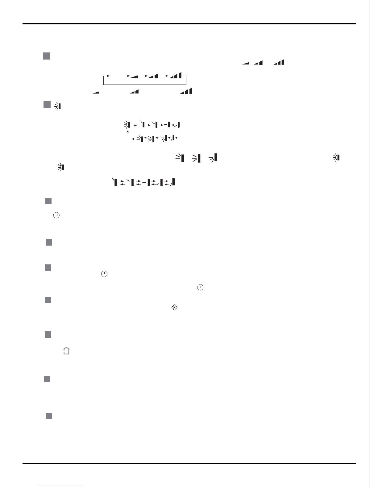
FAN
:
This button is used for setting fan speed in the sequence that goes from AUTO,
,
to
then back to Auto.
,
,
Aut o
Low speed
Medium speed
High speed
:
Press this button to set up &down swing angle, which circularly changes as below:
OFF
5
6
8
This remote controller is universal . If any command , or is sent out,the unit will carry out the command as
indicates the guide louver swings as:
mode, set temperature is not adjustable.
Pressing X-FAN button in COOL or DRY mode,the icon is displayed and the indoor fan will continue operation for 10 min utes in
order to dry the indoor unit even though you have turned off the unit.After energization, X-FAN OFF is defaulted. X-FAN is not available
X-FAN:
10
Press CLOCK button, blinking. Within 5 seconds , pressing + or - button adjusts the present time.Holding down either button above 2
CLOCK :
setting , press CLOCK button again to confirm the setting,and then
9
TIMER OFF:
Press this button to initiate the auto-off timer. To cancel the auto-timer program,simply press the button again.TIMER OFF setting is the
8
TIMER ON:
Press this button to initiate the auto-ON timer. To cancel the auto-timer program,simply press this button again.After press of this button,
7
button changes the time setting by 1 minute. Holding down either button rapidly changes the time setting by 1
10 minutes. Within 5 seonds after setting, press TIMER ON button to confirm.
disappears and "ON "blinks
.0
0:00 is displayed for ON time setting. Within 5 seconds, press + or - button to adjust the time value.
will be constantly displayed.
Every press of either
minute and then
same as TIMER ON.
seconds increases or decreases the time by 1 minute every 0.5 second and then by 10 minutes every 0.5 second. During blinking after
in AUTO,FAN or HEAT mode.
11
TEMP:
TURBO:
Press this button to activate / deactivate the Turbo function which enables the unit to reach the preset temperature in shortest time. In
COOL mode, the unit will blow strong cooling air at super high fan speed. In HEAT mode, the unit will blow strong heating air at super
12
high fan speed. (This function is not applicable for some models)
SLEEP:
Press this button to go into the SLEEP operation mode. Press it again to cancel. This function is available in COOL , HEAT (Only for
13
models with heating function) or DRY mode to maintain the most comfortable temperature for you.
Press this button to select displaying set temperature or ambient temperature. When the
temperature display is changed from other state
to “
”, the ambient temperature is
changed. When other signal is received, the set temperature will be displayed. If the user
does not set temperature display state, it will display set temperature.

20
Function and Control
Press "++" and "--" buttons simultaneously
to lock or unlock the keypad. If the remote controller is locked, is displayed.
At unit OFF, press "MODE
"
and
" - "
buttons simultaneously to switch between and .
ć
About switch between fahrenheit and cenrigrade
ƾ
●
●
●
●
●
1.Remove the battery cover plate from the rear of the remote controller.(As shown in the figure)
2.Take out the old batteries.
3.Insert two new AAA1.5V dry batteries, and pay attention to the polarity.
4. Close the battery cover plate.
When replacing the batteries, do not use old or different types of batteries. Otherwise, it may
If the remote controller will not be used for a long time, please remove batteries to prevent
batteries from leaking.
The operation should be performed in its receiving range.
It should be kept 1m away from the TV set or stereo sound sets.
If the remote controller does not operate normally, please take the batteries out and replace
them after 30 seconds. If still not operating properly, replace the batteries.
Sketch map for
replacing batteries
Notes:
3
4
and About lock
2
4
and
Press LIGHT button to turn on the display's light and press this button again to turn off the display 's light. If the light is
LIGHT:
14
In this case,
pressing any button, blinks three times.
tunrned on , is displayed. If the light is tunrned off disappears.
cause malfunction.
Replacement of Batteries
21
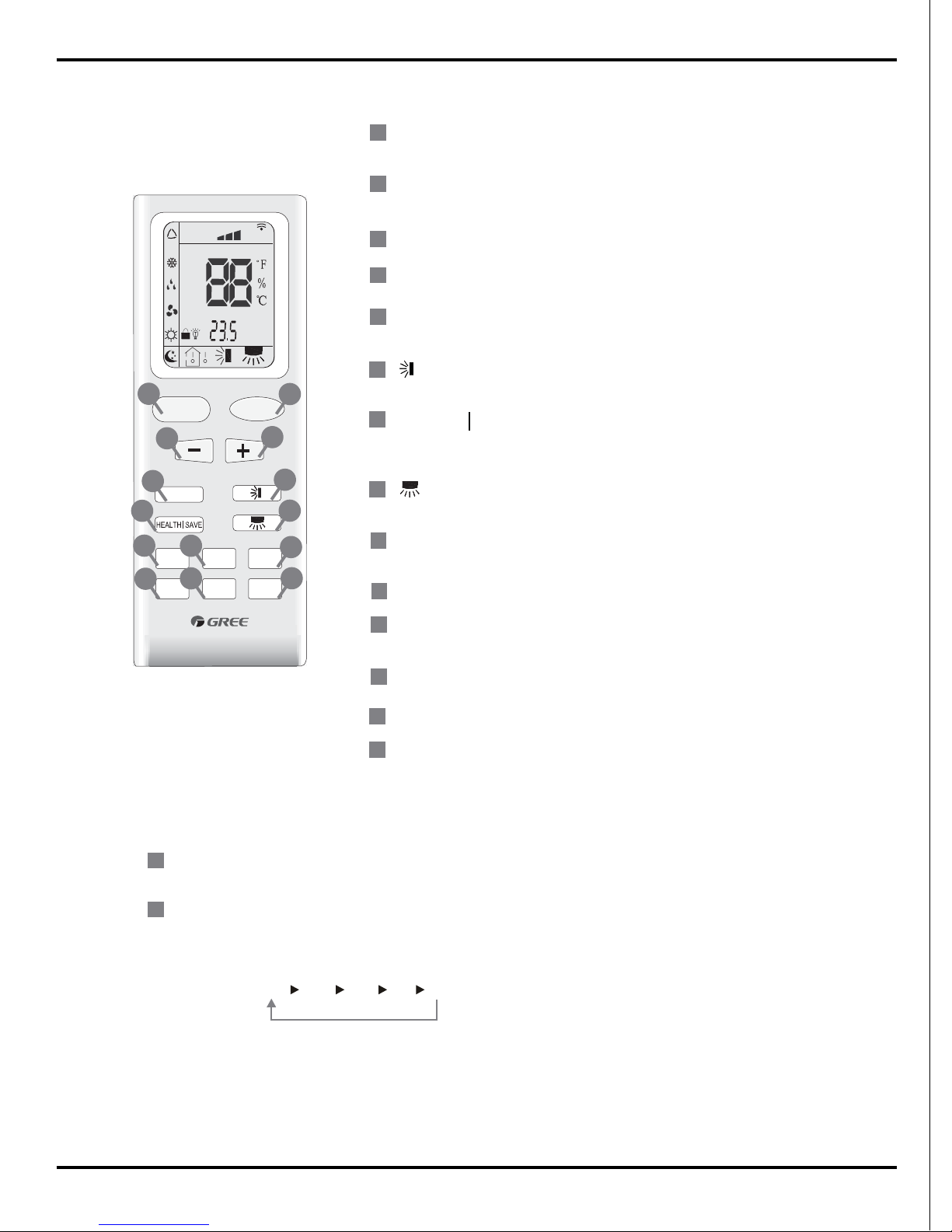
Function and Control
Press this button to start or stop operation.
ON/OFF
MODE
+
-
Press it to select operation mode
(AUTO/COOL/DRY/FAN/HEAT).
: Press it to increase temperature setting.
: Press it to decrease temperature setting.
FA
HEALTH SAVE
N
Press it to set up &down swing angle.
TIMER
X-FAN
(X-FAN is the alternative expression of BLOW for the
purpose of understanding.)
Press it to select health mode on or off.
TEMP
TURBO
SLEEP
LIGHT
Press it to set fan speed.
Press it set auto-on timer/auto-off timer.
1
2
7
4
3
5
6
Press it to set left & right swing angle.
8
11
9
10
12
13
14
FAN
AUTO
OPER
HEALTH
AIR
FILTER
TURBO
ON/OFF
X-FAN
HOUR
HUMIDITY
ON/OFF
MODE
FAN
X-FAN
TURBO
TEMP
TIMER
SLEEP
LIGHT
2
11
7
10
13
9
43
12
8
6
14
5
1
Press it to turn on/off the light.
Remote controller description
ON/OFF :
MODE :
1
2
Press this button to start the unit operation .Press this button again to stop the unit operation.
Each time you press this button,a mode is selected in a sequence that goes from AUTO, COOL,DRY, FAN,
and HEAT
*,
as the following:
AUTO
COOL
DRY
FAN HEAT
*
*Note:Only for models with heating
function.
After energization, AUTO mode is defaulted. In AUTO mode, the set temperature will not be displayed on the
mode in accordance with the room temp
erature to make indoor room comfortable.
LCD, and the unit will automatically select the suitable operation
YB1F4
 Loading...