

Gree NCHS1B(U), NCHS2B(U), NCHS4B(U), NCHS8B(U) Owner's Manual
Owner's Manual
Original Instructions
Commercial Air Conditioners
GMV5 HR Heat Recovery Cooling and Heating Mode
Exchanger
Models:
NCHS1B(U) NCHS2B(U)
NCHS4B(U) NCHS8B(U)
Preface
For correct installation and operation, please read this manual carefully. Before reading the
manual, please note that:
This is the safety alert symbol. It is used to alert you to potential personal injury
hazards. Obey all safety messages that follow this symbol to avoid possible
injury or death.
This mark indicates procedures which, if improperly performed, might lead to the
death or serious injury of the user.
This mark indicates procedures which, if improperly performed, might possibly
result in personal harm to the user, or damage to propert y.
NOTICE is used to address practices not related to personal injury.
(1) The design standard of multi VRF system comforms to related standard of sales countries.
(2) To ensure safety when operating this system, please strictly follow the instructions in this manual.
(3) The total capacity of running indoor units must not exceed that of the outdoor units. Otherwise, the cooling
(heating) effect of each IDU would be poor.
(4) Make sure that this manual is kept by direct operators and maintainers.
(5) In case of malfunction, please examine the following items and contact our authorized service centers as soon
as possible.
1) Air conditioner’s nameplate (model, cooling capacity, product code, ex-factory date)
2) Malfunction status (detail description of conditions before and after malfunction occurs)
(6) All units have been strictly tested and proved to be qualified before ex-factory. To avoid damage or operation
failure which may be caused by improper disassembly, please do not disassemble units by yourself. If
disassembly is needed, please contact our authorized service centers.
(7) All graphics and information in this manual are only for reference. Manufacturer reserves the right for changes
in terms of sales or production at any time and without prior notice.
(8) Under the standby status, the unit will consume a little power for ensuring reliability of the complete unit,
maintaining normal communication and preheating refrigerant. When the unit won’t be used for a long time,
please cut off the power of the complete unit. However, please preheat it when operating the unit next time.
This appliance can be used by children aged from 8 years and above and persons with
reduced physical, sensory or mental capabilities or lack of experience and knowledge if they have
been given supervision or instruction concerning use of the appliance in a safe way and understand
the hazards involved. Children shall not play with the appliance. Cleaning and user maintenance
shall not be made by children without supervision.
DISPOSAL: Do not dispose this product as unsorted municipal waste. Collection of
such waste separately for special treatment is necessary.

Contents
1 Safety Precautions ............................................................................................................................. 1
2 Product Introduction ......................................................................................................................... 2
2.1 Names of Main Parts ........................................................................................................................... 2
2.2 Parameter table .................................................................................................................................... 3
3 Preparation before installation ......................................................................................................... 3
3.1 Standard Accessory ............................................................................................................................. 3
3.2 Installation Site ...................................................................................................................................... 4
3.3 Selection Requirement for Communication Wire ............................................................................ 5
3.4 Wiring Requirment................................................................................................................................ 7
4 Installation Instruction ...................................................................................................................... 7
4.1 Installation of Cooling and Heating Mode Exchanger ..................................................................... 7
4.1.1 Dimension of Outdoor Unit and Mounting Hole Position ......................................................................... 7
4.1.2 Suspend the mode exchanger ................................................................................................................... 11
4.2 Pipe Connection ................................................................................................................................. 13
4.2.1 Installation instruction for silencer ............................................................................................................. 13
4.2.2 Notices for welding ...................................................................................................................................... 15
4.2.3 Precautions for the Installation of Connection Pipe ................................................................................ 16
4.2.4 Selection of Y-type branch .......................................................................................................................... 17
4.2.5 Thermal insulation for pipeline ................................................................................................................... 17
4.2.6 Support and protection of pipeline ............................................................................................................ 19
4.2.7 Size requirement for branch pipe and piping ........................................................................................... 21
4.3 Installation and Test for Drainage Hose .......................................................................................... 23
4.3.1 Precaustions for the Installation of Drainage Hose................................................................................. 23
4.3.2 Installation of Drainage Hose ..................................................................................................................... 24
5 Cable Connection ............................................................................................................................ 25
5.1 Connection of Cable and Terminal of Wiring Board ...................................................................... 26
5.2 Connect Power Cord...........................................................................................................................27
5.3 Conenct Communication Wire of Indoor Unit and Outdoor Unit ................................................. 29
6 Routine Maintenance ...................................................................................................................... 30
6.1 Notice before Seasonal Use ............................................................................................................. 30
6.2 Maintenance after Seasonal Use ..................................................................................................... 31
7 Troubleshooting .............................................................................................................................. 31
GMV5 HR Heat Recovery Cooling and Heating Mode Exchanger
1
1 Safety Precautions
(1) Follow this instruction to complete the installation work. Please carefully read this manual before unit
startup and service.
(2) Wire size of power cord should be large enough. The damaged power cord and connection wire should
be replaced by exclusive cable.
(3) After connecting the power cord, please fix the electric box cover properly in order to avoid accident.
(4) Never fail to comply with the nitrigen charge requirements. Charge nitrogen when welding pipes.
(5) Never short-circiut or cancel the pressure switch to prevent unit damage.
(6) Please firstly connect the wired controller before energization, otherwise wired controller cannot be
used.
(7) Before using the unit, please check if the piping and wiring are correct to avoid water leakage, refrigerant
leakage, electric shock, or fire etc.
(8) Do not insert fingers or objects into air outlet/inlet grille.
(9) Open the door and window and keep good ventilation in the roo m to avoid oxygen deficit when the
gas/oil supplied heating equipment is used.
(10) Never start up or shut off the air conditioner by means of directly plug or unplug the power cord.
(11) Turn off the unit after it runs at least five minutes; otherwise it will inf luence oil return of the compressor.
(12) Do not allow children operate this unit.
(13) Do not operate this unit with wet hands.
(14) Turn off the unit or cut off the power supply before cleaning the unit, otherwise electric shock or injury
may happen.
(15) Never spray or flush water towards unit, otherwise malfunction or electric shock may happen.
(16) Do not expose the unit to the moist or corrosive circumstances.
(17) Under cooling mode, please don't set the room temperature too low and keep the temperature difference
between indoor and outdoor unit within 5ºC(41ºF).
(18) User is not allowed to repair the unit. Fault service may cause electric shock or fire accidents. Please
contact Gree appointed service center for help.
(19) Before installation, please check if the power supply is in accordance with the requirements specified on
the nameplate. And also take care of the power safety.
(20) Installation should be conducted by dealer or qualified personnel. Please do not attempt to install the
unit by yourself. Improper handling may result in water leakage, electric shock or fire disaster etc.
(21) Be sure to use the exclusive accessory and part to prevent the water leakage, electric shock and fire
accidents.
(22) Make sure the unit can be earthed properly and soundly after plugging into the sock et so as to avoid
electric shock. Please do not connect the ground wire to gas pipe, water pipe, lightning rod or telephone
line.
(23) Electrify the unit 8 hours before operation. Please switch on for 8 hours before operation. Do not cut off
the power when 24 hours short-time halting (to protect the compressor).
(24) If refrigerant leakage happens during installation, please ventilate immediately. Poisonous gas will
emerge if the refrigerant gas meets fire.
(25) Volatile liquid, such as diluent or gas will damage the unit appearance. Only use soft cloth with a little
neutral detergent to clean the outer casing of unit.
(26) If anything abnormal happens (such as burning smell), please power off the unit and cut off the main
power supply, and then immediately contact Gree appointed service center. If abnormality keeps going,
the unit might be damaged and lead to electric shock or fire.
GMV5 HR Heat Recovery Cooling and Heating Mode Exchanger
2
Gree Electric Appliances, Inc. of Zhuhai will not assume responsibility for any personal injury or
property loss caused by improper installation, improper test running, and unnecessary repair or not
following the instructions of this manual.
2 Product Introduction
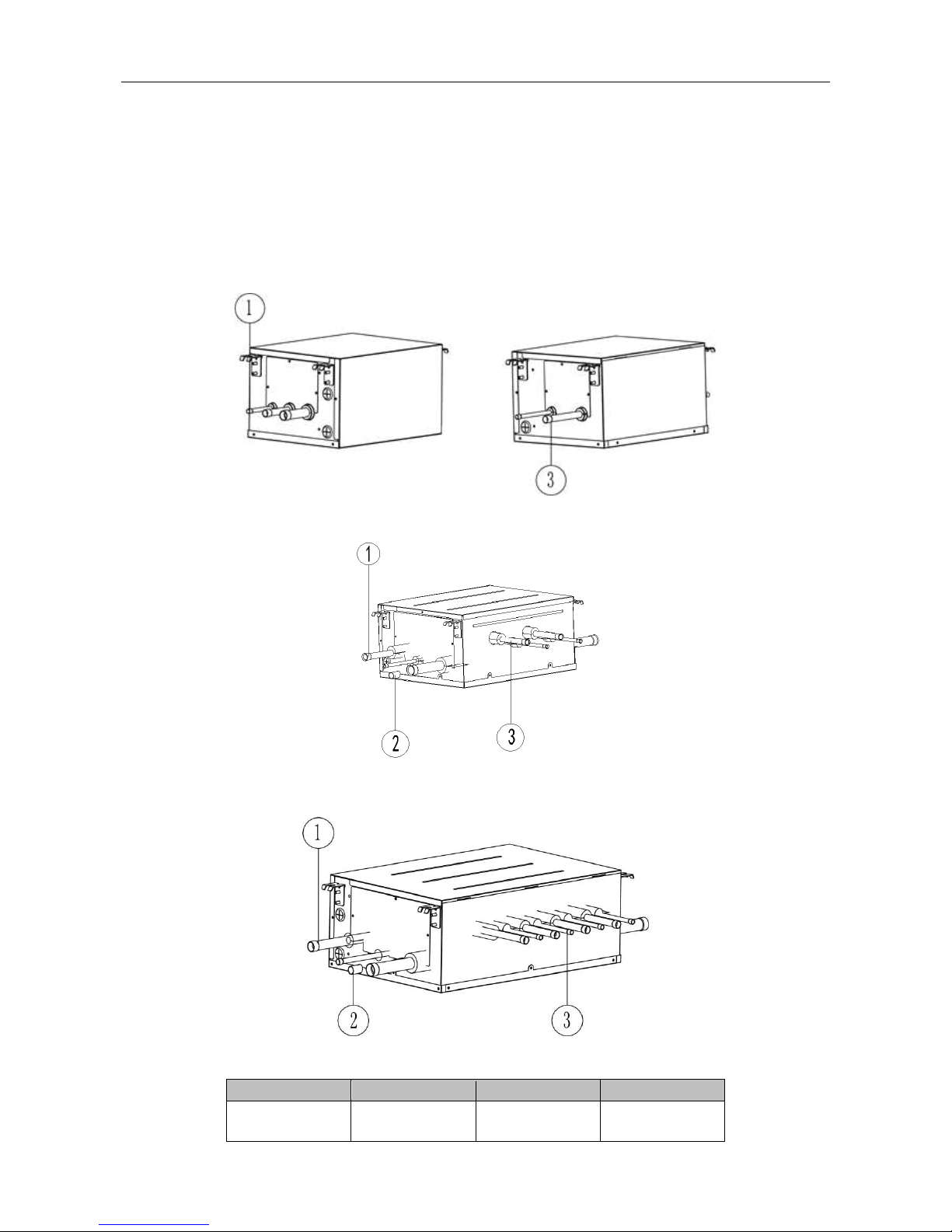
2.1 Names of Main Parts
One-to-one Cooling and Heating Mode Exchanger
Fig. 2.1.1
One-to-two Cooling and Heating Mode Exchanger
Fig. 2.1.2
One-to-more Cooling and Heating Mode Exchanger
Fig. 2.1.3
No.
①
② ③
Name
Connection pipe of
outdoor unit
Drainage pipe
Connection pipe of
indoor unit
GMV5 HR Heat Recovery Cooling and Heating Mode Exchanger
3
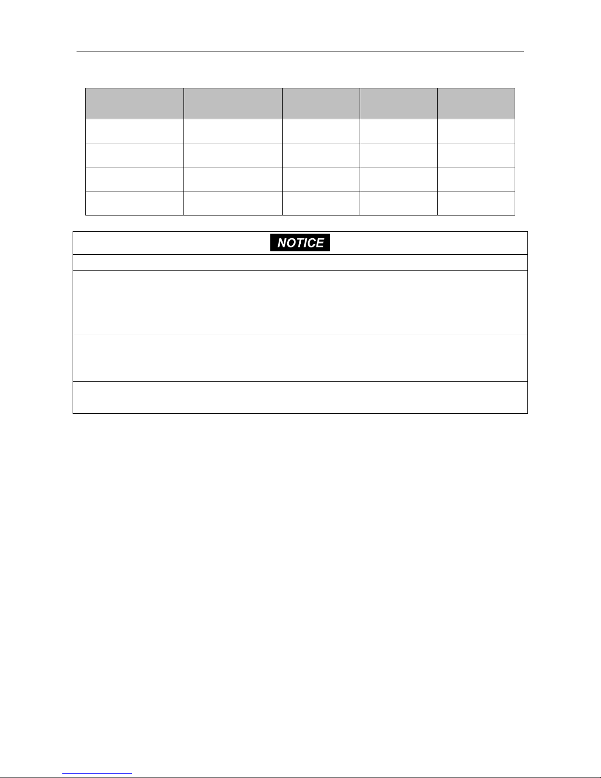
2.2 Parameter table
Model
Unit
NCHS1B(U)
NCHS2B(U)
NCHS4B(U)
NCHS8B(U)
Rated voltage
V
208/230V
208/230V
208/230V
208/230V
Max. quantity of connecting indoo r
unit
- 8 16
32
64
Max. branch quantity of
connecting indoor unit
- 1 2 4 8
Max. quantity of connecting indoor
unit for each branch
- 8 8
8
8
Max. total capacity of connecting
indoor unit for each branch
Btu/h
48500
48500
48500
48500
Total capacity of connecting
indoor unit for mode convertor
Btu/h
48500
96000
154000
232000
Size of high pressure pipe (mode
convertor connects outdoor unit)
mm(in.)
15.9(5/8)
19.05(3/4)
22.2(7/8)
22.2(7/8)
Size of low pressure gas pipe
(mode convertor connects outdoor
unit)
mm(in.)
22.2(7/8)
22.2(7/8)
28.6(1-1/8)
28.6(1-1/8)
Size of liquid pipe (mode
convertor connects outdoor unit)
mm(in.)
9.52(3/8)
9.52(3/8)
12.7(1/2)
15.9(5/8)
Size of gas pipe (mode convertor
connects indoor unit)
mm(in.)
15.9(5/8)
15.9(5/8)
15.9(5/8)
15.9(5/8)
Size of liquid pipe (mode
convertor connects indoor unit)
mm(in.)
9.52(3/8)
9.52(3/8)
9.52(3/8)
9.52(3/8)
3 Preparation before installation
NOTICE
!
The product photos are only for reference. The unit for size is mm(in.), except otherwise
stated.
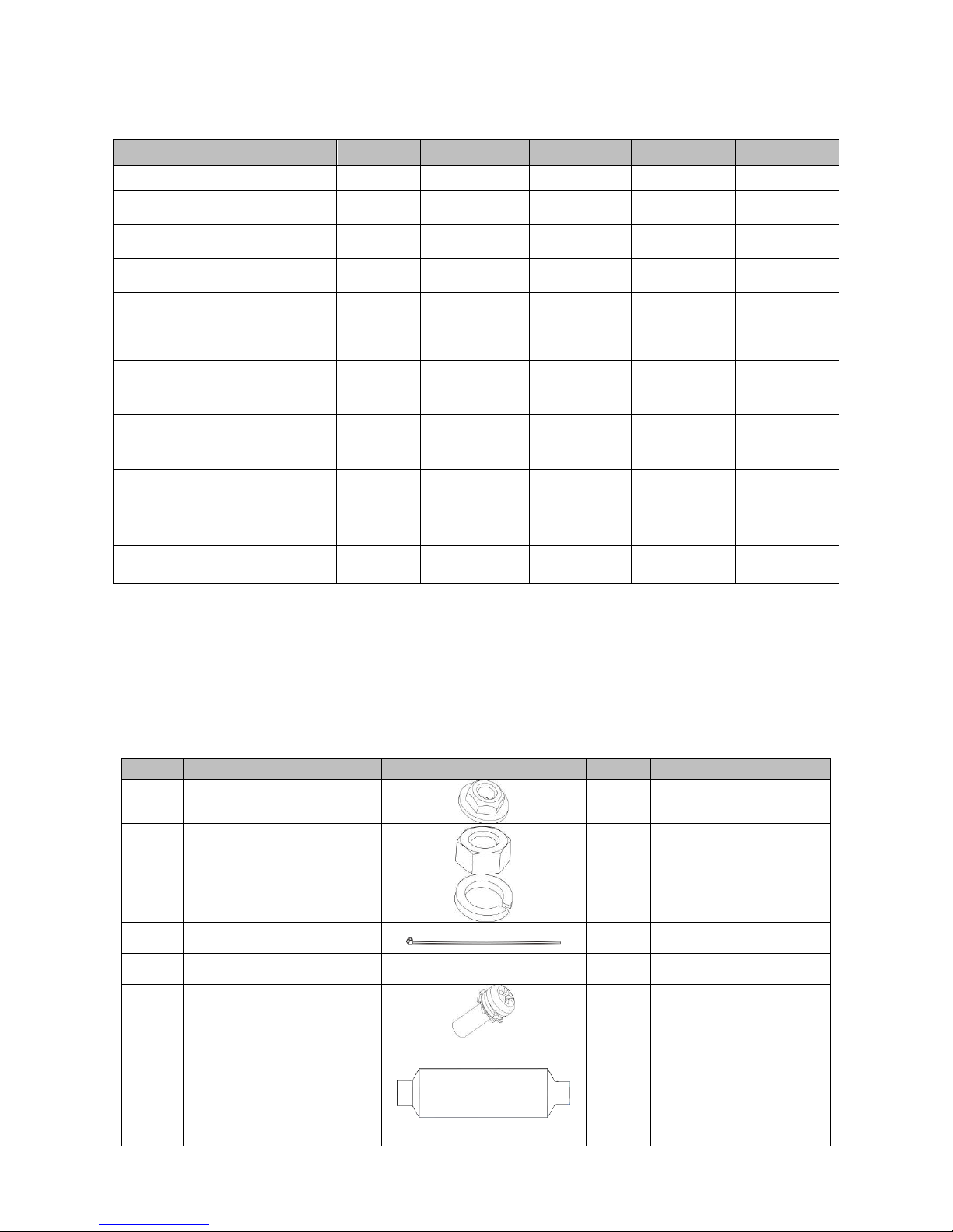
3.1 Standard Accessory
Please use below provided standard parts according to requirement.
No.
Name
Photo
Quantity
Purpose
1
M10X8
Nut with washer M10X8
4
Used for hanging mode
exchanger
2
Nut M10
(hesagon nut M10X8.4)
4
Used for hanging mode
exchanger
3
Washer 10
(spring washer M10X2.6)
4
Used for hanging mode
exchanger
4
High-tenperature tieline
8
Wrap sponges at the
connection position
5
Installation template
/
1
Used for drilling holes at the
ceiling
6
M4X12
(green bonding screw M4X12)
1
Used for connecting the
earthing cord
7
silencer 1
1
The sizes of both nozzles
are IDΦ19.3 (3/4)and
ODΦ19(3/4),nozzle
ODΦ19(3/4) is used for
connecting the high
pressure gas pipe of
NCHS2B(U).
GMV5 HR Heat Recovery Cooling and Heating Mode Exchanger
4
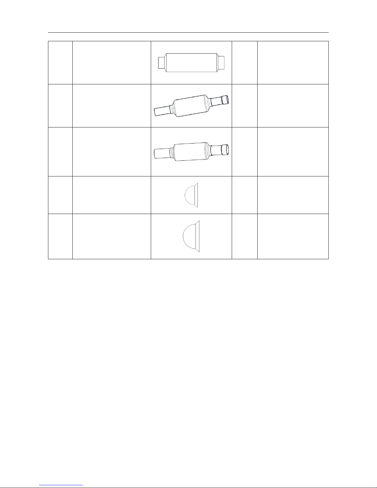
8
silencer 2
1
The sizes of both nozzles
are IDΦ22.3(7/8) and
ODΦ28(1-1/8),nozzle
OdΦ28(1-1/8) is used for
connecting the high
pressure gas pipe of
NCHS2B(U).
9
silencer 1
1
The sizes of both nozzles
are IDΦ22.3(7/8) and
Φ22(7/8),nozzle Φ22(7/8)
is used for connecting the
high pressure gas pipe of
NCHS4B(U) and
NCHS8B(U).
10
silencer 2
1
The sizes of both nozzles
are IDΦ28.3(1-1/8) and
Φ28(1-1/8),nozzle
Φ28(1-1/8) is used for
connecting the low
pressure gas pipe of
NCHS4B(U) and
NCHS8B(U).
11
sealing cap 1
1
Used for blocking the liquid
pipe nozzle
12
sealing cap 2
1
Used for blocking the high
pressure gas pipe nozzle of
NCHS2B(U), or used for
blocking the low pressure
gas pipe nozzle of
NCHS4B(U) and
NCHS8B(U).
The packed attachments should be subject to actual objects. If there are any alterations, there will
be no further notice.
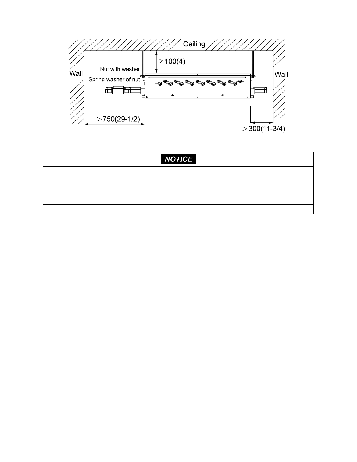
3.2 Installation Site
(1) Make sure the hanging parts can hold the weight of unit.
(2) Water can be drained out from the drainage hose conveniently.
(3) No obstacles at outlet and inlets. Keep the air ventilation in good condition.
(4) Connect either left or right side of converter to outdoor unit for piping according to installation
space, as shown in the fig.3.1, the space used for maintenance should be ensured.
(5) Please keep the unit away from those positions where there’s thermal sournce, inflammable gas
and smog.
(6) The unit is the cassette type (concealed type).
(7) Indoor unit, outdoor unit, mode exchanger power cord and connection cord should be kept 1m
(39-3/8in.) above away from TV and radio for preventing graphic interference and noise. (Even
the distance is 1m (39-3/8in.), if there’s strong electric wave, there’s still noise).
Unit:mm(in.)
GMV5 HR Heat Recovery Cooling and Heating Mode Exchanger
5
Fig. 3.1
① The installation of the unit must comp ly with national and local safety regulations.
② Users can’t install the unit by theirselves, because the intallation quality will affect the operation directionly.
After purchasing the unit, please contact with dealer. The unit must be installed and debugged by
professional installer.
③ The unit can be put through power only after all installation work is finished.
3.3 Selection Requirement for Communication Wire
NOTICE
!
If the unit is installed at the place where there’s strong electromagnetic interference, the
communication wire between indoor unit and wired controller must adopt shield wire, and the
communication wire between indoor unit and indoor unit (outdoor unit) must adopt twisted wire with
shielding function.
Comunicaton Wire between mode exchanger and indoor unit, outdoor unit:
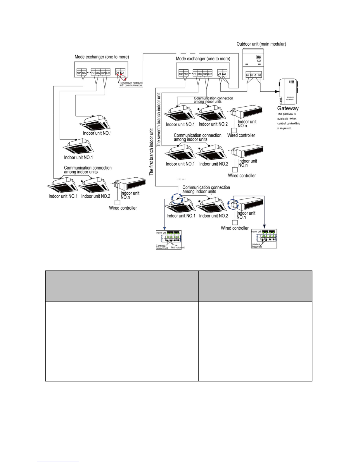
GMV5 HR Heat Recovery Cooling and Heating Mode Exchanger
6
Fig.3.2
Type of wire
Total length of
communication wire between
mode exchanger
and
another indoor/outdoor unit:
L/m(in.)
Wire size
Remarks
Light/Ordinary
polyvinyl chloride
sheathed cord
L≤1000(3280-5/6)
AWG16~AWG18
①
If the wire diameter is enlarged to 2 ×AWG16,
the total communication length can reach
1500m (4921-1/4ft.).
②
The cord shall be Circular cord (the cores
shall be twisted together).
③
If unit is installed in places with intense
magnetic field or strong interference, it is
necessary to use shielded wire.
GMV5 HR Heat Recovery Cooling and Heating Mode Exchanger
7
3.4 Wiring Requirment
Model
Power
Fuse Capacity(A)
Minimum Circuit
Ampacity(A)
Maximum
Overcurrent
Protection(A)
NCHS1B(U)
208/230V 1Ph 60Hz
15
10
15
NCHS2B(U)
208/230V 1Ph 60Hz
15
10
15
NCHS4B(U)
208/230V 1Ph 60Hz
15
10
15
NCHS8B(U)
208/230V 1Ph 60Hz
15
10
15
①
Above circuit breaker and power cord specition are selected according to the max power (max currrect).
②
Specification of power cord is based on the working c ondition where ambient temperature is 40℃(104℉)
and multi-core copper cable (working temperature is 90℃(194℉), e.g. power cable with YJV cross-linked
copper, insulated PE and PVC sheath) is lying on the surface of slot. If working condition changes, please
adjust the specification according to national standard.
③
Specification of circuit breaker is based on the working condition where ambient temperature of circuit
breaker is 40℃(104℉). If working condition changes, please adjust the specification according to national
standard.
④
When installating the cut-off device next to the unit, the min space between every two levels of cut -off
device should be 3mm (1/8in.) (for indoor unit and outdoor unit).
4 Installation Instruction
4.1 Installation of Cooling and Heating Mode Exchanger
4.1.1 Dimension of Outdoor Unit and Mounting Hole Position
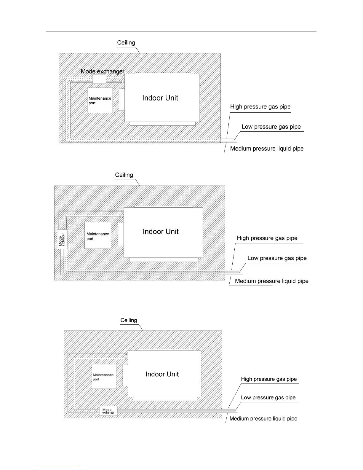
After the unit is installed, a maintenance port should be reserved at the electric box side of unit for
maintenance. The position of maintenance port should be lower than the lower size of unit.
The mode exchanger shall be installed near the maintenance port or air return of indoor unit. (Note:
if it is installed near the air return, please make sure not to affect air return and maintenance).
The following pictures detailedly describe the installation of maintenance port and mode exchanger:
GMV5 HR Heat Recovery Cooling and Heating Mode Exchanger
8
Fig. 4.1
Fig. 4.2
Fig. 4.3
 Loading...