

Page 1

Technical Product Guide
+Multi Zone Inverter
Heat Pump Systems
World Class Comfort
Page 2

Table of Contents
+Multi Product Overview............................ 2
+Multi Outdoor Units ............................... 6
+Multi Neo Wall Mount Units ....................... 35
+Multi Ceiling Cassettes ...........................43
+Multi Slim Concealed Ducts .......................54
+Multi Universal Floor/Ceiling ......................69
+Multi Mini-Floor Consoles ......................... 78
+Multi Wired Tether Controller......................86
Refer to individual listings within each of the above sections, for specific page references for:
Product Nomenclature, Features and Benefits, Product Performance Data, Dimensional Specifications,
Clearance Specifications, Electrical Wiring, Condensate Removal, Indoor Unit Combinations.
Page 3

PRODUCT OVERVIEW
SUPERIOR DESIGNS PROVIDE EASY SOLUTIONS TO COMPLEX PROBLEMS
GREE Ductless Multi Zone systems provide quiet comfort and energy ecient heating and cooling in up to
five dierent rooms – without ductwork. For most residential and light commercial applications, this is the ideal
solution to balance comfort, eciency and ease of installation. This Inverter-driven system oers Seasonal
Energy Eciency Ratings (SEER) up to 16. With individual room control and variable speed compressor
operation, comfort is boosted throughout your home or oce, while utility bills are held in check.
Gree’s exclusive G-10 Inverter technology powers the twin rotary compressor inside the Multi Zone
outdoor compressor section. The G-10 Inverter constantly adjusts the compressor speed to maintain
a comfortable room temperature. This saves energy, reduces outdoor noise and maintains a steady
room temperature by eliminating the harsh starts and stops of conventional systems.
When laying out a new project, you’ll appreciate the flexibility of Gree’s Multi Zone Systems. A single outdoor unit
can simultaneously power up to five indoor units while eliminating expensive ductwork. Without those ducts, your
installation is simpler, faster and more cost-eective. And the flexibility doesn’t stop there, as you can also mix
and match your choice of Wall Mount, Ceiling Cassette, Concealed Duct, Universal Floor/Ceiling and Mini Floor
Console indoor units to create a unique heating and cooling system to perfectly fit any project.
No pipe sweating
No sweating is needed for the pipe connection
between the indoor and outdoor units. All
piping connections are flared to simplify and
ease the piping installation.
Simple Wiring
No special or hard-to-find communication
wire is needed between the indoor and
outdoor units. The system uses common
14-4 AWG stranded copper THHN 600V
wire. The system’s communication is ready
as soon as the electrical wiring between the
indoor and outdoor units is complete.
High Lift Design
Gree’s High Lift design allows for extended
piping length, up to 262 feet total, as well as
50 feet of vertical lift from the condensing
units. This allows for greater flexibility in the
layout of the system.
Outdoor Unit
Power
Supply
1st Branching
Section
Indoor Unit
Transmission System
From Outdoor Unit to
the Indoor Unit:
82ft
82ft
Between Indoor Units:
Height Dierence
50ft
and Outdoor Unit:
50ft
Between Indoor Unit
Height Dierence
Allows up to 262 feet of pipe length
Energy Saving
Multi Zone systems allow each room to be individually controlled. Only those rooms requiring air
conditioning (or heating) are cooled (or heated), and all of it is accomplished without ductwork.
In addition, Gree’s G-10 inverter technology reduces energy waste, maximizes eciency and
achieves up to 16 SEER.
2
Page 4

PRODUCT OVERVIEW
Self-Diagnostics System
Each indoor and outdoor unit continuously runs
a series of multi-point diagnostic tests on the
system, to automatically scan for unacceptable
operating conditions or malfunctions. If such
conditions occur, the system takes corrective
action or stops. The fault code will be shown
on the indoor, outdoor and wired controller displays.
Problems and system status are displayed with
comprehensive diagnostic codes to simplify system
troubleshooting and shorten repair times.
Flexible Design
Gree’s Multi Zone systems have many advantages
for both the property owner and the installer.
Up to five indoor units, powered by a single
outdoor unit, results in flexible zoning solutions
for almost any application. Various styles of
indoor units may be mixed and matched in any
combination to create a unique, multiple zone
heating and cooling system. Choose from Wall
Mount, Ceiling Cassette, Slim Duct, Universal
Floor/Ceiling and Mini Floor Console indoor units.
All are lightweight and compact enough to be
installed on the wall or in any ceiling space.
Diagnostic
Code
E1
E2
E3
E4
E5
E6
E7
E9
F4
Malfunction
Compressor High Pressure Protection
Indoor Coil Anti-Freeze Protection
Low Pressure Protection
High Discharge Temperature Protection
Compressor High Temperature Protection
Indoor/Outdoor Communication Failure
Heating & Cooling Modes Conflict
Condensate Water Too High
Outdoor Coil Sensor Failure
One outdoor unit
can power up to
5 indoor units.
Intelligent Control
Gree’s Multi Zone components use state-of-the
art intelligent controls to generate the ultimate
in room comfort. G-10 Inverter technology
delivers the exact level of required capacity (from
10% to 100%) to maintain room temperature and
humidity in the comfort range. The optimized PID
controls maintain the room temperature within
less than ±1.0°F of the room setpoint temperature.
The result is a virtually constant room temperature
without the typical fluctuations that occur with a
conventional fixed speed ON/OFF system.
Ductless Saves Money
Realize energy savings by eliminating heat loss
from inecient and leaky ductwork. The average
ducted air distribution system could reduce
overall system eciency by up to 30 percent.
Eliminating ductwork allows you to downsize
equipment while upsizing performance.
Cooling
Gree Inverter Control System
Conventional Fixed Speed System
Room temp.
3
Page 5

MULTI OUTDOOR UNITS
Models:
MULTI18HP230V1AO
MULTI24HP230V1AO
MULTI30HP230V1AO
MULTI36HP230V1AO
MULTI42HP230V1AO
Page 6

+Multi Outdoor Units
Table of Contents
Features and Benefits ..............................6-7
Product Nomenclature/AHRI Certification .............. 8
Product Performance Data .........................9-13
Dimensional Specifications........................14-16
Clearance Specifications.............................17
Electrical Wiring.................................18-19
Condensate Removal................................19
Indoor Unit Combinations........................ 20-28
Extended Performance Ratings ................... 29-33
Page 7

+Multi Outdoor Units
Each +Multi heat pump is powered by Gree’s energy ecient G-10 Inverter and a variable speed compressor. These units can
heat and cool up to five zones without distribution boxes, and all oer the G-10 advantages of energy savings, noise reduction
and room temperature consistency. Each outdoor coil also features a corrosion-resistant Gold Fin coating to withstand corrosive
environments and to further promote energy eciency.
FEATURES AND BENEFITS
High Eciency G-10 Inverter
The G-10 Inverter uses a broad range of variable frequencies to drive the compressor, marking the
highest level of inverter control technology available today. Unlike conventional technology that
generally regulates room temperature by running at maximum capacity and then shutting o
completely, G-10 Inverter technology eliminates these harsh starts/stops. This cutting edge functionality
results in quicker arrival at desired temperatures and superior maintenance of consistent comfort
levels. Higher eciency and significant energy savings? Yes, it yields those too.
Heat Pump Advantage
Multi Zone heat pumps, powered by the G-10 Inverter, provide the same heating capacity as electric
heat, while using as little as 1/3 the electricity.
Intelligent Defrost
The Intelligent Defrost function increases room comfort and saves energy by eliminating unnecessary
defrost cycles. In heating mode, the control system monitors the outdoor coil for frost buildup,
and the system switches to defrost mode only when frost buildup is actually detected. This avoids
unnecessary and wasteful defrosts.
Time Guard
Among the system’s many safeties is a Time Guard function to prevent rapid cycling of the compressor.
A protective three-minute time delay restricts compressor restarts after shuto.
Gold Fin Condenser
The system’s corrosion-resistant Gold Fin condenser coating (1500hr salt spray rating) is made with
a gold-colored anti-corrosion epoxy. This technology maintains excellent heat transfer properties
while extending coil life against damage from salt air and salt water in seacoast installations.
6
Page 8

FEATURES AND BENEFITS
Low Voltage Start Up
Having stable electrical power is not always an option. The Gree Multi Zone units will operate from
170v to 265v which is suitable for unstable power supply areas.
Self-Diagnosis
With an on-board computer using real-time diagnostics, the Gree Multi Zone system helps to
prolong its own life. The automatic diagnosis feature continuously scans for unacceptable operating
conditions or malfunctions. If such conditions occur, the system takes corrective action or stops.
Fault codes are shown on the unit display to facilitate easy troubleshooting and repair.
Agency Listings
All systems are listed with AHRI (Air conditioning, Heating, and Refrigeration Institute) and are
ETL Certified per standards.
7/5 Year Limited Warranty
Enjoy one of the most comprehensive warranties in the industry. Seven (7) years
on compressor and Five (5) years on all parts.
7
Page 9

+Multi Outdoor Units
NOMENCLATURE
Series Designation
MULTI - Multi Zone
Cooling Capacity
18 - 18,000 BtuH
24 - 24,000 BtuH
30 - 30,000 BtuH
36 - 36,000 BtuH
42 - 42,000 BtuH
Model Type
AC - Cooling Only
HP - Heat Pump
HC - Heat/Cool
MULTI 42 1 A O
HP 230V
Product Type
S - System
O - Outdoor Units
H - Indoor High Wall
D - Indoor Duct
C - Indoor Cassette
F - Indoor Floor/Ceiling
Revision Level
Style/Color Designation
Electrical Rating
230V - 208/230V 60Hz 1PH
115V - 115V 60Hz 1PH
AHRI CERTIFICATION
MODEL NUMBER BRAND AHRI CERTIFICATION
MULTI18HP230V1AO GREE 7084754
MULTI24HP230V1AO GREE 7084908
MULTI30HP230V1AO GREE 7084759
MULTI36HP230V1AO GREE 7084898
MULTI42HP230V1AO GREE 7084899
MULTI48HP230V1AO GREE 7117354
MULTI56HP230V1AO GREE 7117355
8
Page 10

PERFORMANCE SPECIFICATIONS
Cooling
COOLING CAPACITY
MODEL NUMBER SEER EER
MULTI18HP230V1A 16 10.2 18,000 (7,000-21,000) 23 °F 118 °F
MULTI24HP230V1A 16 8.2 26,000 (7,500-33,000) 23 °F 118 °F
MULTI30HP230V1A 16 7.3 29,000 (7,500-34,000) 23 °F 118 °F
MULTI36HP230V1A 16 8.0 34,000 (8,530-34,120) 23 °F 118 °F
MULTI42HP230V1A 16 9.3
RATED
(BtuH) MIN
,000
40
RANGE
(BtuH)
(8,530-46,403) 23 °F 118 °F
OUTDOOR TEMP
OPERATING RANGE
MAX
Heating
HEATING CAPACITY
MODEL NUMBER HSPF
MULTI18HP230V1A 8.2 19,000 (8,530-22,600) 5 °F 80 °F
MULTI24HP230V1A 8.2 29,000 (7,500-35,000) 5 °F 80 °F
RATED
(BtuH) MIN
RANGE
(BtuH)
OUTDOOR TEMP
OPERATING RANGE
MAX
MULTI30HP230V1A 8.2
MULTI36HP230V1A 8.2 35,800 (10,663-40,944) 5 °F 80 °F
MULTI42HP230V1A 8.2 44,500 (10,663-47,768) 5 °F 80 °F
Notes:
1.
Ratings are based on: Cooling Standard: 80°F (26.7°C) db, 67°F (19.4°C) wb air entering indoor unit and 95°F (35°C) db air entering
outdoor unit. Heating Standard: 70°F (21.1°C) db air entering indoor unit and 47°F (8.3°C) db, 43°F (6.1°C) wb air entering outdoor unit.
2. Ratings are based on 25 ft. (7.62 m) of interconnecting refrigerant lines.
3. All system ratings are based on fan coil units operating at high fan speed. Consult Physical Data tables for air flows at selected fan speeds.
Legend:
EER - Energy Eciency Ratio
HSPF - Heating Seasonal Performance Ratio
SEER - Seasonal Energy Eciency Ratio
30
,400
(7,500-36,000) 5 °F 80 °F
NUMBER OF PORTS
MODEL NUMBER BRAND
MULTI18HP230V1AO EXV 2
MULTI24HP230V1AO EXV 3
MULTI30HP230V1AO EXV 4
MULTI36HP230V1AO EXV 4
FOR INDOOR UNITS
MULTI42HP230V1AO EXV 5
9
Page 11

+Multi Outdoor Units
AIR FLOW DATA
Outdoor Unit
MODEL NUMBER
MULTI18HP230V1A 1,530
MULTI24HP230V1A 1,530
MULTI30HP230V1A 1,530
MULTI36HP230V1A 2,177
MULTI42HP230V1A 3,237
SOUND DATA
Outdoor Unit
MODEL NUMBER SOUND POWER SOUND PRESSURE
MULTI18HP230V1A 66 dBA 56 dBA
MULTI24HP230V1A 66 dBA 56 dBA
MULTI30HP230V1A 66 dBA 56 dBA
MULTI36HP230V1A 69 dBA 59 dBA
AIR FLOW (CFM)
MULTI42HP230V1A 68 dBA 58 dBA
Note:
1. Sound pressure ratings are estimated sound pressure measurements, 3 feet from unit.
2. Sound power ratings are per AHRI 270 and AHRI 350.
PRODUCT WEIGHT
MODEL NUMBER
MULTI18HP230V1A 95 lbs. 106 lbs.
MULTI24HP230V1A 135 lbs. 146 lbs.
MULTI30HP230V1A 153 lbs. 165 lbs.
MULTI36HP230V1A 161 lbs. 172 lbs
MULTI42HP230V1A 225 lbs. 247 lbs.
PRODUCT WEIGHT
NET OPERATING GROSS SHIPPING
10
Page 12

REFRIGERATION SPECIFICATIONS & DATA
Refrigerant Charge
MODEL NUMBER
MULTI18HP230V1A R-410A 48 oz. 33 ft. 0.2 oz./ft.
MULTI24HP230V1A R-410A 78 oz. 98 ft. 0.2 oz./ft.
MULTI30HP230V1A R-410A 78 oz. 131 ft. 0.2 oz./ft.
MULTI36HP230V1A R-410A 102 oz. 131 ft. 0.2 oz./ft.
MULTI42HP230V1A R-410A 169 oz. 164 ft. 0.2 oz./ft.
TYPE
REFRIGERANT
FACTORY
SYSTEM
CHARGE
MAX TOTAL PIPE
LENGTH W/O ADDING
REFRIGERANT
ADDITIONAL
CHARGE
LEVEL
PIPING LENGTH REQUIREMENTS
L = L1
L2
+ + +
L
S
L
=L1 + L2 + ......L
TOTAL
n
...Ln
Refrigerant Piping Lengths
IN PIPE LENGTH
M
MODEL NUMBER
PER INDOOR
UNIT (Ln)
MULTI18HP230V1A 10 ft. 33 ft. 66 ft.
MULTI24HP230V1A 10 ft. 66 ft. 230 ft.
MULTI30HP230V1A 10 ft. 66 ft. 230 ft.
MULTI36HP230V1A 10 ft. 82 ft. 230 ft.
MULTI42HP230V1A 10 ft. 82 ft. 262 ft.
MAX PIPE
LENGTH PER
INDOOR UNIT (L
)
n
MAX TOTAL PIPE
LENGTH PER
INDOOR UNIT (L
TOTAL
)
11
Page 13

+Multi Outdoor Units
PIPING HEIGHT REQUIREMENTS
H2
H1
L1
L2
L3
Refrigerant Piping Height
MAX ELEVATION
MODEL NUMBER
MULTI18HP230V1A 33 ft. 16 ft.
MULTI24HP230V1A 66 ft. 25 ft.
MULTI30HP230V1A 66 ft. 25 ft.
MULTI36HP230V1A 82 ft. 25 ft.
MULTI42HP230V1A 82 ft. 25 ft.
BETWEEN OUTDOOR &
INDOOR UNITS (H1)
MAX ELEVATION
BETWEEN
INDOOR UNITS (H1)
...Ln
12
Page 14

ELECTRICAL DATA
Outdoor Unit
RATED POWER
MODEL NUMBER
SUPPLY
(volt-phase-hz)
MULTI18HP230V1A 208/230v-1ph-60hz 187-253 1.7 1.6
MULTI24HP230V1A 208/230v-1ph-60hz 187-253 3.1 2.8
MULTI30HP230V1A 208/230v-1ph-60hz 187-253 3.5 2.9
MULTI36HP230V1A 208/230v-1ph-60hz 187-253 4.3 3.6
MULTI42HP230V1A 208/230v-1ph-60hz 187-253 4.4 4.6
VOLTAGE
RANGE
(volts)
RATED INPUT POWER
(KW)
COOLING HEATING
Outdoor Unit
MODEL NUMBER
MULTI18HP230V1A 7.6 7.5 13 20
MULTI24HP230V1A 13.5 12.4 20 30
MULTI30HP230V1A 15.3 12.6 26 45
COOLING HEATING
RATED INPUT CURRENT (amps)
MIN CIRCUIT
AMP (MCA)
MAX FUSE
SIZE (amps)
MULTI36HP230V1A 19.2 15.8 28 45
MULTI42HP230V1A 19.5 20.5 29 50
Outdoor Unit
MODEL NUMBER
MULTI18HP230V1A 9.6 27 0.5 1/12 60
MULTI24HP230V1A 14.7 45 0.6 1/12 60
MULTI30HP230V1A 19.6 45 0.6 1/12 60
MULTI36HP230V1A 21.0 45 0.7 1/8 120
MULTI42HP230V1A 21.5 67 1.1 1/6 140
Legend: RLA – Rated Load Amps HP – Horse Power
RLA (amps) LRA (amps)
RLA (amps) HP INPUT POWER
COMPRESSOR
OUTDOOR FAN
(watts)
13
Page 15

+Multi Outdoor Units
DIMENSIONAL SPECIFICATIONS
Model No: MULTI18HP230V1A 18,000 BtuH
Suction/Gas Line Port Size
Port A 3/8-in OD Flared
Port B 3/8-in OD Flared
Liquid Line Port Size
Port A 1/4-in OD Flared
Port B 1/4-in OD Flared
Model No: MULTI24HP230V1A 24,000 BtuH
Suction/Gas Line Port Size
Port A 3/8-in OD Flared
Port B 3/8-in OD Flared
Port C 3/8-in OD Flared
Liquid Line Port Size
Port A 1/4-in OD Flared
Port B 1/4-in OD Flared
Port C 1/4-in OD Flared
14
Page 16

DIMENSIONAL SPECIFICATIONS
Model No: MULTI30HP230V1A 30,000 BtuH
Suction/Gas Line Port Size
Port A 3/8-in OD Flared
Port B 3/8-in OD Flared
Port C 3/8-in OD Flared
Port D 3/8-in OD Flared
Liquid Line Port Size
Port A 1/4-in OD Flared
Port B 1/4-in OD Flared
Port C 1/4-in OD Flared
Port D 1/4-in OD Flared
Model No: MULTI36HP230V1A 36,000 BtuH
Suction/Gas Line Port Size
Port A 3/8-in OD Flared
Port B 3/8-in OD Flared
Port C 1/2-in OD Flared
Port D 5/8-in OD Flared
Liquid Line Port Size
Port A 1/4-in OD Flared
Port B 1/4-in OD Flared
Port C 1/4-in OD Flared
Port D
3/8-in OD Flared
15
Page 17

+Multi Outdoor Units
DIMENSIONAL SPECIFICATIONS
Model No: MULTI42HP230V1A 42,000 BtuH
Suction/Gas Line Port Size
Port A 3/8-in OD Flared
Port B 3/8-in OD Flared
Port C 1/2-in OD Flared
Port D 1/2-in OD Flared
Port E 5/8-in OD Flared
Liquid Line Port Size
Port A 1/4-in OD Flared
Port B 1/4-in OD Flared
Port C 1/4-in OD Flared
Port D 1/4-in OD Flared
Port E
3/8-in OD Flared
16
Page 18

MINIMUM OUTDOOR CLEARANCE SPECIFICATIONS
The unit installation must meet or exceed the following minimum clearances for proper operation.
A
BD
C
Air Outlet
Outdoor Unit Minimum Distance
A 20 in
B 24 in
C 78 in
D 12 in
E 20 in
Air Inlet
E
17
Page 19

+Multi Outdoor Units
ELECTRICAL WIRING
The main power is supplied to the outdoor unit. System must be on a single dedicated circuit. Use appropriate
wire size and circuit breaker (or fuse) size for proper system overcurrent protection. Follow all local building
codes and NEC (National Electrical Code) regulations.
Interconnecting Cable Wiring Diagram
The indoor units are powered by the outdoor unit. The interconnecting cable between the outdoor and indoor
units must be a 14/4 AWG stranded copper conductors THHN 600V unshielded wire. The interconnecting cable
should not be buried underground and must be recognized by UL or ETL and CSA certified.
Note: Use shield cable if installation is in close proximity of RF and EMI transmitting devices.
18
Page 20

ELECTRICAL WIRING
Local codes may require a disconnect switch within sight of the indoor unit. For these installations, use
a DFS Disconnect Switch Accessory Kit (Part No: DFS-SWITCH-A) to break wires going to the N(1), 2, 3,
terminals on the indoor unit, as shown in the wiring diagram below:
Interconnecting Cable with Disconnect Switch Wiring Diagram
CONDENSATE REMOVAL
Install condensate drain to bottom of outdoor unit to safely and eectively route condensate water to a
safe location. Use a flexible condensate drain hose to fit over the factory 5/8-inch (16mm) drainage port.
The high wall indoor units have an internal condensate trap. Adding an external trap is not required.
All condensate drains must meet local codes and regulations. If adequate gravity drainage cannot be
provided, a field-installed condensate pump must be used. Refer to manufacturer’s installation instructions,
specifications and operating details supplied with condensate pump.
19
Page 21

+Multi Outdoor Units
INDOOR UNIT COMBINATIONS
SELECTION CRITERIA
When selecting a variable speed system, match the system capacity to the calculated load of the building.
Since a variable speed system can accommodate a wide range of loads, it is important to understand the
percentage of time that the system will be required to run at both maximum and minimum load points.
Generally there will be more load diversification in residential applications (shifting from low load to high
load). Commercial applications tend to be more steady during normal daytime hours, and go to low load
levels after hours. The tables below are guidelines for selecting the proper size.
Model No: MULTI18HP230V1A 18,000 BtuH
Cooling Capacity (BtuH)
INDOOR UNITS
COMBINATIONS
9K 9,000 5,118~11,940 9,000
12K 12,000 6,824~15,000 12,000
9K+9K 18,000 7,000~21,000 9,000 9,000
9K+12K 21,000 7,100~22,000 9,000 12,000
12K+12K 24,000 7,200~22,000 12,000 12,000
RATED SYSTEM
CAPACITY
(BtuH)
CAPACITY RATING
(MIN – MAX)
(BtuH)
INDOOR
UNIT A
(BtuH)
INDOOR
UNIT B
(BtuH)
Heating Capacity (BtuH)
INDOOR UNITS
COMBINATIONS
9K 9,500 5,460~15,360 9,500
12K 13,000 6,150~16,400 13,000
9K+9K 19,000 8,530~22,600 9,500 9,500
9K+12K 22,500 8,530~22,600 9,500 13,000
RATED SYSTEM
CAPACITY
(BtuH)
CAPACITY RATING
(MIN – MAX)
(BtuH)
INDOOR
UNIT A
(BtuH)
INDOOR
UNIT B
(BtuH)
12K+12K 26,000 8,530~22,600 13,000 13,000
Note: It is critical to size the outdoor unit for the entire building load and each indoor unit for its individual zone load.
Capacity data is based on the following conditions:
Cooling Nominal Test Conditions Heating Normal Test Conditions
Indoor: 80°F DB/67°F WB Indoor: 70°F DB/60°F WB
Outdoor: 95°F DB/75°F WB Outdoor: 47°F DB/43°F W
20
Page 22

INDOOR UNIT COMBINATIONS
Model No: MULTI24HP230V1A 24,000 BtuH
Cooling Capacity (BtuH)
INDOOR UNITS
COMBINATIONS
9K+9K 18,000 6,824~26,600 9,000 9,000
9K+12K 21,000 7,165~27,300 9,000 12,000
12K+12K 24,000 7,200~30,000 12,000 12,000
9K+18K 25,000 7,300~32,000 8,400 16,600
12K+18K 25,000 7,400~32,500 10,000 15,000
18K+18K 25,500 7,500~32,500 12,750 12,750
9K+9K+9K 26,000 7,500~34,000 8,667 8,667 8,667
9K+9K+12K 26,000 7,500~34,000 8,000 8,000 10,000
9K+12K+12K 26,000 7,500~34,000 6,000 10,000 10,000
9K+9K+18K 26,000 7,500~34,000 7,000 7,000 12,000
12K+12K+12K 26,000 7,500~34,000 8,667 8,667 8,667
RATED SYSTEM
CAPACITY
(BtuH)
CAPACITY RATING
(MIN – MAX)
(BtuH)
INDOOR
UNIT A
(BtuH)
INDOOR
UNIT B
(BtuH)
INDOOR
UNIT C
(BtuH)
Heating Capacity (BtuH)
INDOOR UNITS
COMBINATIONS
RATED SYSTEM
CAPACITY
(BtuH)
CAPACITY RATING
(MIN – MAX)
(BtuH)
INDOOR
UNIT A
(BtuH)
INDOOR
UNIT B
(BtuH)
INDOOR
UNIT C
(BtuH)
9K+9K 19,000 71,00~33,000 9,500 9,500
9K+12K 22,500 7,100~33,500 9,500 13,000
12K+12K 26,000 7,200~34,000 13,000 13,000
9K+18K 27,000 7,300~34,000 9,000 18,000
12K+18K 28,000 7,400~34,000 11,200 16,800
18K+18K 28,500 7,400~34,400 14,250 14,250
9K+9K+9K 29,000 7,500~35,000 9,667 9,667 9,667
9K+9K+12K 29,000 7,600~35,000 9,000 9,000 11,000
9K+12K+12K 29,000 7,600~35,000 6,000 11,500 11,500
9K+9K+18K 29,000 7,600~35,000 6,000 6,000 17,000
12K+12K+12K 29,000 7,600~35,000 9,667 9,667 9,667
Note: It is critical to size the outdoor unit for the entire building load and each indoor unit for its individual zone load.
Capacity data is based on the following conditions:
Cooling Nominal Test Conditions Heating Normal Test Conditions
Indoor: 80°F DB/67°F WB Indoor: 70°F DB/60°F WB
Outdoor: 95°F DB/75°F WB Outdoor: 47°F DB/43°F W
21
Page 23

+Multi Outdoor Units
INDOOR UNIT COMBINATIONS
Model No: MULTI30HP230V1A 30,000 BtuH
Cooling Capacity (BtuH)
RATED
INDOOR UNITS
COMBINATIONS
9K+9K 18,000 6,824~26,600 9,000 9,000
9K+12K 21,000 7,165~27,300 9,000 12,000
12K+12K 24,000 7,200~30,000 12,000 12,000
9K+18K 25,000 7,300~32,000 8,400 16,600
12K+18K 25,500 7,400~32,500 10,000 15,000
18K+18K 26,000 7,500~32,500 12,750 12,750
9K+9K+9K 26,000 7,500~34,000 8,667 8,667 8,667
9K+9K+12K 26,000 7,500~34,000 8,000 8,000 10,000
9K+12K+12K 26,000 7,500~34,000 6,000 10,000 10,000
9K+9K+18K 26,000 7,500~34,000 7,000 7,000 12,000
12K+12K+12K 26,000 7,500~34,000 8,667 8,667 8,667
9K+12K+18K 27,000 7,500~34,000 6,800 7,200 13,000
12K+12K+18K 28,000 7,500~34,000 6,500 6,500 15,000
9K+9K+9K+9K 29,000 7,500~34,000 7,250 7,250 7,250 7,250
9K+9K+9K+12K 29,000 7,500~34,000 7,000 7,000 7,000 8,000
9K+9K+12K+12K 29,000 7,500~34,000 6,800 6,800 7,700 7,700
SYSTEM
CAPACITY
(BtuH)
CAPACITY
RATING
(MIN – MAX)
(BtuH)
INDOOR
UNIT A
(BtuH)
INDOOR
UNIT B
(BtuH)
INDOOR
UNIT C
(BtuH)
INDOOR
UNIT D
(BtuH)
Heating Capacity (BtuH)
RATED
INDOOR UNITS
COMBINATIONS
9K+9K 19,000 7,100~33,000 9,500 9,500
9K+12K 22,500 7,100~33,500 9,500 13,000
12K+12K 26,000 7,200~34,000 13,000 13,000
9K+18K 27,000 7,300~34,000 9,000 18,000
12K+18K 28,000 7,400~34,000 11,200 16,800
18K+18K 28,500 7,400~34,400 14,250 14,250
9K+9K+9K 29,000 7,500~35,000 9,667 9,667 9,667
9K+9K+12K 29,000 7,600~35,000 9,000 9,000 11,000
9K+12K+12K 29,000 7,600~35,000 6,000 11,500 11,500
9K+9K+18K 29,000 7,600~35,000 6,000 6,000 17,000
12K+12K+12K 29,000 7,600~35,000 9,667 9,667 9,667
SYSTEM
CAPACITY
(BtuH)
CAPACITY
RATING
(MIN – MAX)
(BtuH)
INDOOR
UNIT A
(BtuH)
22
INDOOR
UNIT B
(BtuH)
INDOOR
UNIT C
(BtuH)
INDOOR
UNIT D
(BtuH)
Page 24

INDOOR UNIT COMBINATIONS
Model No: MULTI30HP230V1A 30,000 BtuH (cont.)
Heating Capacity (BtuH)
RATED
INDOOR UNITS
COMBINATIONS
9K+12K+18K 29,000 7,600~35,000 6,802 9,309 12,888
12K+12K+18K 29,000 7,600~35,000 8,567 8,567 11,862
9K+9K+9K+9K 30,500 7,600~36,000 7,625 7,625 7,625 7,625
9K+9K+9K+12K 30,500 7,600~36,000 7,100 7,100 7,100 9,200
9K+9K+12K+12K 31,000 7,600~36,000 6,500 6,500 9,000 9,000
Note: It is critical to size the outdoor unit for the entire building load and each indoor unit for its individual zone load.
Capacity data is based on the following conditions:
Cooling Nominal Test Conditions Heating Normal Test Conditions
Indoor: 80°F DB/67°F WB Indoor: 70°F DB/60°F WB
Outdoor: 95°F DB/75°F WB Outdoor: 47°F DB/43°F W
SYSTEM
CAPACITY
(BtuH)
CAPACITY
RATING
(MIN – MAX)
(BtuH)
INDOOR
UNIT A
(BtuH)
INDOOR
UNIT B
(BtuH)
INDOOR
UNIT C
(BtuH)
INDOOR
UNIT D
(BtuH)
Model No: MULTI36HP230V1A 36,000 BtuH
Cooling Capacity (BtuH)
INDOOR UNITS
COMBINATIONS
RATED
SYSTEM
CAPACITY
(BtuH)
CAPACITY
RATING
(MIN – MAX)
(BtuH)
INDOOR
UNIT A
(BtuH)
INDOOR
UNIT B
(BtuH)
INDOOR
UNIT C
(BtuH)
INDOOR
UNIT D
(BtuH)
9K+9K 17,060 10,236~26,614 8,530 8,530
9K+12K 20,472 10,236~27,297 8,530 12,283
9K+18K 24,226 10,236~31,391 7,506 16,719
9K+24K (2) 27,297 10,236~31,391 6,824 20,472
12K+12K 20,472 10,236~31,391 10,236 10,236
12K+18K 27,297 10,236~32,415 10,577 13,648
12K+24K (2) 27,297 10,236~32,415 10,236 17,060
18K+18K 27,297 10,236~32,415 13,648 13,648
18K+24K (2) 27,297 10,236~32,415 12,283 15,354
24K +24K (2) 27,297 10,236~32,415 13,648 13,648
9K+9K+9K 24,567 10,236~30,709 8,189 8,189 8,189
9K+9K+12K 24,567 10,236~30,709 6,994 7,336 10,236
9K+9K+18K 29,685 10,236~32,756 7,165 7,165 15,354
9K+9K+24K (2) 29,685 10,236~32,756 6,312 6,312 17,060
9K+12K+12K 29,685 10,236~32,756 7,506 11,089 11,089
9K+12K+18K 29,685 10,236~32,756 6,141 10,065 13,477
9K+12K+24K (2) 29,685 10,236~32,756 5,459 8,018 16,207
9K+18K+18K 29,685 10,236~32,756 5,971 11,771 11,771
9K+18K+24K (2) 29,685 10,236~32,756 5,459 9,042 15,184
23
Page 25

+Multi Outdoor Units
INDOOR UNIT COMBINATIONS
Model No: MULTI36HP230V1A 36,000 BtuH (cont.)
Cooling Capacity (BtuH)
RATED
INDOOR UNITS
COMBINATIONS
12K+12K+12K 29,685 10,236~32,756 9,895 9,895 9,895
12K+12K+18K 29,685 10,236~32,756 8,530 8,530 12,624
12K+12K+24K (2) 29,685 10,236~32,756 7,506 7,506 14,672
12K+18K+18K 29,685 10,236~32,756 9,212 12,283 12,283
18K+18K+18K 29,685 10,236~32,756 9,895 9,895 9,895
9K+9K+9K+9K 33,438 10,236~34,121 8,359 8,359 8,359 8,359
9K+9K+9K+12K 33,438 10,236~34,121 7,506 7,506 7,506 10,918
9K+9K+9K+18K 33,438 10,236~34,121 6,824 6,824 6,824 12,283
9K+9K+9K+24K (2) 33,438 10,236~34,121 6,141 6,141 6,141 15,013
9K+9K+12K+12K 33,438 10,236~34,121 6,824 6,824 9,895 9,895
9K+9K+12K+18K 33,438 10,236~34,121 6,312 6,312 8,871 12,283
9K+9K+18K+18K 33,438 10,236~34,121 5,459 5,459 11,260 11,260
9K+12K+12K+12K 33,438 10,236~34,121 7,847 8,530 8,530 8,530
9K+12K+12K+18K 33,438 10,236~34,121 6,141 7,506 7,506 12,283
12K+12K+12K+12K 33,438 10,236~34,121 8,359 8,359 8,359 8,359
SYSTEM
CAPACITY
(BtuH)
CAPACITY
RATING
(MIN – MAX)
(BtuH)
INDOOR
UNIT A
(BtuH)
INDOOR
UNIT B
(BtuH)
INDOOR
UNIT C
(BtuH)
INDOOR
UNIT D
(BtuH)
Heating Capacity (BtuH)
RATED
INDOOR UNITS
COMBINATIONS
9K+9K 22,178 15,354~29,003 11,089 11,089
9K+12K 26,614 15,354~32,756 11,089 15,968
9K+18K 31,494 15,354~33,780 9,758 21,735
9K+24K (2) 32,756 15,354~33,780 8,189 24,567
12K+12K 26,614 15,354~33,780 13,307 13,307
12K+18K 32,756 15,354~33,780 12,693 16,378
12K+24K (2) 32,756 15,354~33,780 12,283 20,472
18K+18K 32,756 15,354~33,780 16,378 16,378
18K+24K (2) 32,756 15,354~33,780 14,740 18,425
24K +24K (2) 32,756 15,354~33,780 16,378 16,378
9K+9K+9K 27,024 15,354~33,780 9,008 9,008 9,008
SYSTEM
CAPACITY
(BtuH)
CAPACITY
RATING
(MIN – MAX)
(BtuH)
INDOOR
UNIT A
(BtuH)
24
INDOOR
UNIT B
(BtuH)
INDOOR
UNIT C
(BtuH)
INDOOR
UNIT D
(BtuH)
Page 26

INDOOR UNIT COMBINATIONS
Model No: MULTI36HP230V1A 36,000 BtuH (cont.)
Heating Capacity (BtuH)
RATED
INDOOR UNITS
COMBINATIONS
9K+9K+12K 27,024 15,354~33,780 7,694 8,069 11,260
9K+9K+18K 35,622 15,354~37,533 8,598 8,598 18,425
9K+9K+24K (2) 35,622 15,354~37,533 7,574 7,574 20,472
9K+12K+12K 35,622 15,354~37,533 9,008 13,307 13,307
9K+12K+18K 35,622 15,354~37,533 7,370 12,078 16,173
9K+12K+24K (2) 35,622 15,354~37,533 6,551 9,622 19,449
9K+18K+18K 35,622 15,354~37,533 7,165 14,126 14,126
9K+18K+24K (2) 35,622 15,354~37,533 6,551 10,850 18,220
12K+12K+12K 35,622 15,354~37,533 11,874 11,874 11,874
12K+12K+18K 35,622 15,354~37,533 10,236 10,236 15,149
12K+12K+24K (2) 35,622 15,354~37,533 9,008 9,008 17,606
12K+18K+18K 35,622 15,354~37,533 11,055 14,740 14,740
18K+18K+18K 35,622 15,354~37,533 11,874 11,874 11,874
9K+9K+9K+9K 40,126 15,354~40,945 10,031 10,031 10,031 10,031
9K+9K+9K+12K 40,126 15,354~40,945 9,008 9,008 9,008 13,102
9K+9K+9K+18K 40,126 15,354~40,945 8,189 8,189 8,189 14,740
9K+9K+9K+24K (2) 40,126 15,354~40,945 7,370 7,370 7,370 18,016
9K+9K+12K+12K 40,126 15,354~40,945 8,189 8,189 11,874 11,874
9K+9K+12K+18K 40,126 15,354~40,945 7,574 7,574 10,645 14,740
9K+9K+18K+18K 40,126 15,354~40,945 6,551 6,551 13,512 13,512
9K+12K+12K+12K 40,126 15,354~40,945 9,417 10,236 10,236 10,236
9K+12K+12K+18K 40,126 15,354~40,945 7,370 9,008 9,008 14,740
12K+12K+12K+12K 40,126 15,354~40,945 10,031 10,031 10,031 10,031
SYSTEM
CAPACITY
(BtuH)
CAPACITY
RATING
(MIN – MAX)
(BtuH)
INDOOR
UNIT A
(BtuH)
INDOOR
UNIT B
(BtuH)
INDOOR
UNIT C
(BtuH)
INDOOR
UNIT D
(BtuH)
Notes: 1) It is critical to size the outdoor unit for the entire building load and each indoor unit for its individual zone load.
2) 24K size is reserved for Ceiling Cassettes, Concealed Ducts, and Floor/Ceilings units only. Not Wall Mount units.
Capacity data is based on the following conditions:
Cooling Nominal Test Conditions: Heating Normal Test Conditions
Indoor: 80°F DB/67°F WB Indoor: 70°F DB/60°F WB
Outdoor: 95°F DB/75°F WB Outdoor: 47°F DB/43°F W
25
Page 27

+Multi Outdoor Units
INDOOR UNIT COMBINATIONS
Model No: MULTI42HP230V1A 42,000 BtuH
Cooling Capacity (BtuH)
RATED
INDOOR UNITS
COMBINATIONS
9K+9K 20,472 11,942~30,709 8,530 8,530
9K+12K 20,472 11,942~30,709 8,530 11,942
9K+18K 24,226 11,942~30,709 7,506 16,719
9K+24K (2) 27,297 11,942~30,709 6,824 20,472
12K+12K 20,472 11,942~27,297 10,236 10,236
12K+18K 27,297 11,942~30,709 10,577 16,719
12K+24K (2) 32,415 11,942~37,533 10,236 22,178
18K+18K 32,415 11,942~37,533 16,207 16,207
18K+24K (2) 32,415 11,942~37,533 13,989 18,766
24K +24K (2) 32,415 11,942~37,533 16,207 16,207
9K+9K+9K 24,567 11,942~30,709 8,189 8,189 8,189
9K+9K+12K 24,567 11,942~30,709 6,994 7,336 10,236
9K+9K+18K 32,415 11,942~37,533 8,018 8,018 16,378
9K+9K+24K (2) 35,486 11,942~41,628 8,189 8,189 19,107
9K+12K+12K 29,685 11,942~32,756 8,530 10,577 10,577
9K+12K+18K 35,486 11,942~41,628 8,530 10,918 16,037
9K+12K+24K (2) 39,580 11,942~46,405 7,847 9,553 22,178
9K+18K+18K 39,580 11,942~46,405 7,165 15,013 15,013
9K+18K+24K (2) 39,580 11,942~46,405 6,824 13,648 19,107
9K+24K+24K (2) 39,580 11,942~46,405 5,800 16,890 16,890
12K+12K+12K 35,486 11,942~41,628 11,771 11,771 11,942
12K+12K+18K 35,486 11,942~41,628 10,918 10,918 13,648
12K+12K+24K (2) 39,580 11,942~46,405 10,065 10,065 19,449
12K+18K+18K 39,580 11,942~46,405 9,553 15,013 15,013
12K+18K+24K (2) 39,580 11,942~46,405 9,042 14,160 16,378
12K+24K+24K (2) 39,580 11,942~46,405 8,530 15,525 15,525
18K+18K+18K 39,580 11,942~46,405 13,136 13,136 13,307
18K+18K+24K (2) 39,580 11,942~46,405 12,283 12,283 15,013
9K+9K+9K+9K 35,486 11,942~41,628 8,871 8,871 8,871 8,871
9K+9K+9K+12K 35,486 11,942~41,628 8,189 8,189 8,189 10,918
9K+9K+9K+18K 39,580 11,942~46,405 7,847 7,847 7,847 16,037
9K+9K+9K+24K (2) 39,580 11,942~46,405 6,824 6,824 6,824 19,107
9K+9K+12K+12K 35,486 11,942~41,628 7,165 7,165 10,577 10,577
9K+9K+12K+18K 39,580 11,942~46,405 6,824 6,824 10,577 15,354
9K+9K+12K+24K (2) 39,580 11,942~46,405 6,312 6,312 9,553 17,572
9K+9K+18K+18K 39,580 11,942~46,405 6,483 6,483 13,307 13,307
9K+9K+18K+24K (2) 39,580 11,942~46,405 6,141 6,141 10,407 16,890
9K+12K+12K+12K 39,580 11,942~46,405 7,847 10,577 10,577 10,577
9K+12K+12K+18K 39,580 11,942~46,405 7,165 8,700 8,700 15,013
9K+12K+12K+24K (2) 39,580 11,942~46,405 6,483 7,933 7,933 17,231
9K+12K+18K+18K 39,580 11,942~46,405 6,483 8,189 12,454 12,454
SYSTEM
CAPACITY
(BtuH)
CAPACITY
RATING
(MIN – MAX)
(BtuH)
INDOOR
UNIT A
(BtuH)
INDOOR
UNIT B
(BtuH)
INDOOR
UNIT C
(BtuH)
INDOOR
UNIT D
(BtuH)
INDOOR
UNIT E
(BtuH)
26
Page 28

INDOOR UNIT COMBINATIONS
Model No: MULTI42HP230V1A 42,000 BtuH (cont.)
Cooling Capacity (BtuH)
RATED
INDOOR UNITS
COMBINATIONS
9K+18K+18K+18K 39,580 11,942~46,405 5,800 11,260 11,260 11,260
12K+12K+12K+12K 39,580 11,942~46,405 9,895 9,895 9,895 9,895
12K+12K+12K+18K 39,580 11,942~46,405 8,359 8,359 8,359 14,501
12K+12K+12K+24K (2) 39,580 11,942~46,405 7,506 7,506 7,506 17,060
12K+12K+18K+18K 39,580 11,942~46,405 7,847 7,847 11,942 11,942
9K+9K+9K+9K+9K 39,580 11,942~46,405 7,916 7,916 7,916 7,916 7,916
9K+9K+9K+9K+12K 39,580 11,942~46,405 7,421 7,421 7,421 7,421 9,895
9K+9K+9K+9K+18K 39,580 11,942~46,405 6,824 6,824 6,824 6,824 12,283
9K+9K+9K+9K+24K (2)
9K+9K+9K+12K+12K 39,580 11,942~46,405 7,165 7,165 7,165 9,042 9,042
9K+9K+9K+12K+18K 39,580 11,942~46,405 6,483 6,483 6,483 8,274 11,857
9K+9K+9K+18K+18K 39,580 11,942~46,405 6,483 6,483 6,483 10,065 10,065
9K+9K+12K+12K+12K 39,580 11,942~46,405 6,483 6,483 8,871 8,871 8,871
9K+9K+12K+12K+18K 39,580 11,942~46,405 5,971 5,971 8,018 8,018 11,601
9K+12K+12K+12K+12K 39,580 11,942~46,405 6,483 8,274 8,274 8,274 8,274
9K+12K+12K+12K+18K 39,580 11,942~46,405 6,141 7,592 7,592 7,592 10,662
12K+12K+12K+12K+12K 39,580 11,942~46,405 7,916 7,916 7,916 7,916 7,916
SYSTEM
CAPACITY
(BtuH)
39,580 11,942~46,405 6,483 6,483 6,483 6,483 13,648
CAPACITY
RATING
(MIN – MAX)
(BtuH)
INDOOR
UNIT A
(BtuH)
INDOOR
UNIT B
(BtuH)
INDOOR
UNIT C
(BtuH)
INDOOR
UNIT D
(BtuH)
INDOOR
UNIT E
(BtuH)
Heating Capacity (BtuH)
RATED
INDOOR UNITS
COMBINATIONS
9K+9K 25,591 15,354~33,780 10,662 14,928
9K+12K 25,591 15,354~33,780 10,662 14,928
9K+18K 30,282 15,354~33,780 9,383 20,899
9K+24K (2) 34,121 15,354~33,533 8,530 25,591
12K+12K 25,591 15,354~30,026 12,795 12,795
12K+18K 34,121 15,354~37,533 13,222 20,899
12K+24K (2) 40,519 15,354~42,651 12,795 27,723
18K+18K 40,519 15,354~42,651 20,261 20,261
18K+24K (2) 40,519 15,354~42,651 17,487 23,458
24K+24K (2) 40,519 15,354~42,651 20,261 20,261
9K+9K+9K 30,709 15,354~40,945 10,236 10,236 10,236
9K+9K+12K 30,709 15,354~40,945 8,745 9,171 12,795
9K+9K+18K 40,519 15,354~42,651 10,024 10,024 20,472
9K+9K+24K (2) 44,357 15,354~45,040 10,236 10,236 23,884
9K+12K+12K 37,107 15,354~40,945 10,662 13,222 13,222
9K+12K+18K 44,357 15,354~45,040 10,662 13,648 20,046
9K+12K+24K (2) 45,040 15,354~47,769 8,929 10,871 25,239
9K+18K+18K 45,040 15,354~47,769 8,155 17,084 17,084
9K+18K+24K (2) 45,040 15,354~47,769 7,766 15,532 21,742
9K+24K+24K (2) 45,040 15,354~47,769 6,599 19,220 19,220
12K+12K+12K 44,357 15,354~45,040 14,716 14,716 14,928
SYSTEM
CAPACITY
(BtuH)
CAPACITY
RATING
(MIN – MAX)
(BtuH)
INDOOR
UNIT A
(BtuH)
INDOOR
UNIT B
(BtuH)
INDOOR
UNIT C
(BtuH)
INDOOR
UNIT D
(BtuH)
INDOOR
UNIT E
(BtuH)
27
Page 29

+Multi Outdoor Units
INDOOR UNIT COMBINATIONS
Model No: MULTI42HP230V1A 42,000 BtuH (cont.)
Heating Capacity (BtuH)
RATED
INDOOR UNITS
COMBINATIONS
12K+12K+18K 44,357 15,354~45,040 13,648 13,648 17,060
12K+12K+24K (2) 45,040 15,354~47,769 11,454 11,454 22,131
12K+18K+18K 45,040 15,354~47,769 10,871 17,084 17,084
12K+18K+24K (2) 45,040 15,354~47,769 10,291 16,112 18,637
12K+24K+24K (2) 45,040 15,354~47,769 9,707 17,668 17,668
18K+18K+18K 45,040 15,354~47,769 14,948 14,948 15,143
18K+18K+24K (2) 45,040 15,354~47,769 13,979 13,979 17,084
9K+9K+9K+9K 44,357 15,354~47,769 11,089 11,089 11,089 11,089
9K+9K+9K+12K 44,357 15,354~47,769 10,236 10,236 10,236 13,648
9K+9K+9K+18K 45,040 15,354~47,769 8,929 8,929 8,929 18,248
9K+9K+9K+24K (2) 45,040 15,354~47,769 7,766 7,766 7,766 21,742
9K+9K+12K+12K 44,357 15,354~47,769 8,956 8,956 13,222 13,222
9K+9K+12K+18K 45,040 15,354~47,769 7,766 7,766 12,038 17,473
9K+9K+12K+24K (2) 45,040 15,354~47,769 7,182 7,182 10,871 19,995
9K+9K+18K+18K 45,040 15,354~47,769 7,377 7,377 15,143 15,143
9K+9K+18K+24K (2) 45,040 15,354~47,769 6,988 6,988 11,843 19,220
9K+12K+12K+12K 45,040 15,354~47,769 8,929 12,038 12,038 12,038
9K+12K+12K+18K 45,040 15,354~47,769 8,155 9,902 9,902 17,084
9K+12K+12K+24K (2) 45,040 15,354~47,769 7,377 9,028 9,028 19,609
9K+12K+18K+18K 45,040 15,354~47,769 7,377 9,318 14,170 14,170
9K+18K+18K+18K 45,040 15,354~47,769 6,599 12,812 12,812 12,812
12K+12K+12K+12K 45,040 15,354~47,769 11,260 11,260 11,260 11,260
12K+12K+12K+18K 45,040 15,354~47,769 9,513 9,513 9,513 16,501
12K+12K+12K+24K (2) 45,040 15,354~47,769 8,540 8,540 8,540 19,415
12K+12K+18K+18K 45,040 15,354~47,769 8,929 8,929 13,590 13,590
9K+9K+9K+9K+9K 45,040 15,354~47,769 9,008 9,008 9,008 9,008 9,008
9K+9K+9K+9K+12K 45,040 15,354~47,769 8,445 8,445 8,445 8,445 11,260
9K+9K+9K+9K+18K 45,040 15,354~47,769 7,766 7,766 7,766 7,766 13,979
9K+9K+9K+9K+24K (2) 45,040 15,354~47,769 7,377 7,377 7,377 7,377 15,532
9K+9K+9K+12K+12K 45,040 15,354~47,769 8,155 8,155 8,155 10,291 10,291
9K+9K+9K+12K+18K 45,040 15,354~47,769 7,377 7,377 7,377 9,414 13,491
9K+9K+9K+18K+18K 45,040 15,354~47,769 7,377 7,377 7,377 11,454 11,454
9K+9K+12K+12K+12K 45,040 15,354~47,769 7,377 7,377 10,096 10,096 10,096
9K+9K+12K+12K+18K 45,040 15,354~47,769 6,793 6,793 9,124 9,124 13,201
9K+12K+12K+12K+12K 45,040 15,354~47,769 7,377 9,414 9,414 9,414 9,414
9K+12K+12K+12K+18K 45,040 15,354~47,769 6,988 8,639 8,639 8,639 12,133
12K+12K+12K+12K+12K 45,040 15,354~47,769 9,008 9,008 9,008 9,008 9,008
SYSTEM
CAPACITY
(BtuH)
CAPACITY
RATING
(MIN – MAX)
(BtuH)
INDOOR
UNIT A
(BtuH)
INDOOR
UNIT B
(BtuH)
INDOOR
UNIT C
(BtuH)
INDOOR
UNIT D
(BtuH)
INDOOR
UNIT E
(BtuH)
Notes: 1) It is critical to size the outdoor unit for the entire building load and each indoor unit for its individual zone load.
2) 24K size is reserved for Ceiling Cassettes, Concealed Ducts, and Floor/Ceilings units only. Not Wall Mount units.
Capacity data is based on the following conditions:
Cooling Nominal Test Conditions: Heating Normal Test Conditions
Indoor: 80°F DB/67°F WB Indoor: 70°F DB/60°F WB
Outdoor: 95°F DB/75°F WB Outdoor: 47°F DB/43°F W
28
Page 30

EXTENDED PERFORMANCE RATINGS
Model No: MULT18HP230V1A 18,000 BtuH
Cooling Performance
INDOOR ENTERING AIR TEMPERATURES (DB) 50% RH
OUTDOOR AMBIENT
OUTDOOR AMBIENT
TEMPERATURE (DB)
TEMPERATURE (DB)
25°F 22,145 16,443 23,936 17,330 25,587 18,422
35°F 21,641 16,423 23,047 16,825 24,167 17,473
45°F 20,572 15,799 22,000 16,324 23,571 17,089
55°F 19,805 15,329 2 1,1 19 15,839 22,640 16,528
65°F 19,130 14,864 21,049 15,977 22,320 16,316
75°F 18,378 14,371 19,800 15,226 21,296 15,716
85°F 17,640 14,006 18,900 14,591 20,520 15,329
95°F 16,740 13,375 18,000 14,382 19,692 14,789
TC SHC
TC SHC
INDOOR ENTERING AIR TEMPERATURES (DB) 50% RH
62°F
62°F
TC SHC
TC SHC
67 F
67°F
72 F
72°F
TC SHC
TC SHC
105°F 15,840 12,862 17,060 13,614 18,540 14,239
115°F 14,939 12,309 15,839 12,829 16,919 13,248
Heating Performance
OUTDOOR AMBIENT
TEMPERATURE (DB)
(80% RH)
5°F 15,608 15,608 14,731 14,731 14,370 14,370
15°F 16,684 16,684 15,221 15,221 15,130 15,130
25°F 17,702 17,702 16,802 16,802 15,846 15,846
35°F 18,691 18,691 17,300 17,300 16,574 16,574
45°F 19,667 19,667 19,000 19,000 17,849 17,849
55°F 19,693 19,693 19,124 19,124 18,287 18,287
65°F 19,600 19,600 19,314 19,314 18,719 18,719
TC- Total Capacity (BtuH) SHC- Sensible Capacity (BtuH)
Capacity data is based on the following conditions:
Cooling Nominal Test Conditions Heating Normal Test Conditions
Indoor: 80°F DB/67°F WB Indoor: 70°F DB/60°F WB
Outdoor: 95°F DB/75°F WB Outdoor: 47°F DB/43°F W
TC SHC
INDOOR ENTERING AIR TEMPERATURES (DB)
65°F
70°F
TC SHC
75°F
TC SHC
29
Page 31

+Multi Outdoor Units
EXTENDED PERFORMANCE RATINGS
Model No: MULT24HP230V1A 24,000 BtuH
Cooling Performance
OUTDOOR AMBIENT
TEMPERATURE (DB)
25°F 31,988 23,751 34,575 25,032 36,959 26,610
35°F 31,260 23,723 33,291 24,302 34,907 25,238
45°F 29,716 22,821 31,777 23,579 34,047 24,684
55°F 28,608 22,142 30,506 22,879 32,703 23,873
65°F 27,633 21,471 30,405 23,077 32,240 23,567
75°F 26,546 20,759 28,600 21,994 30,760 22,701
85°F 25,480 20,231 27,300 21,075 29,640 22,141
95°F 24,180 19,320 26,000 20,774 28,444 21,361
105°F 22,880 18,579 24,643 19,665 26,780 20,567
115°F 21,578 17,780 22,878 18,531 24,438 19,135
TC SHC
INDOOR ENTERING AIR TEMPERATURES (DB) 50% RH
62°F
TC SHC
67°F
72°F
TC SHC
Heating Performance
OUTDOOR AMBIENT
TEMPERATURE (DB)
(80% RH)
65°F
TC SHC
INDOOR ENTERING AIR TEMPERATURES (DB)
70°F
TC SHC
TC SHC
75°F
5°F 23,823 23,823 22,484 22,484 21,933 21,933
15°F 25,465 25,465 23,232 23,232 23,092 23,092
25°F 27,019 27,019 25,645 25,645 24,186 24,186
35°F 28,528 28,528 26,405 26,405 25,297 25,297
45°F 30,018 30,018 29,000 29,000 27,243 27,243
55°F 30,058 30,058 29,189 29,189 27,912 27,912
65°F 29,916 29,916 29,479 29,479 28,571 28,571
TC- Total Capacity (BtuH) SHC- Sensible Capacity (BtuH)
Capacity data is based on the following conditions:
Cooling Nominal Test Conditions Heating Normal Test Conditions
Indoor: 80°F DB/67°F WB Indoor: 70°F DB/60°F WB
Outdoor: 95°F DB/75°F WB Outdoor: 47°F DB/43°F W
30
Page 32

EXTENDED PERFORMANCE RATINGS
Model No: MULTI30HP230V1A 30,000 BtuH
Cooling Performance
OUTDOOR AMBIENT
INDOOR ENTERING AIR TEMPERATURES (DB) 50% RH
TEMPERATURE (DB)
25°F 35,679 26,492 38,564 27,920 41,224 29,681
35°F 34,867 26,460 37,132 27,106 38,935 28,150
45°F 33,144 25,454 35,444 26,300 37,976 27,532
55°F 31,909 24,697 34,026 25,519 36,476 26,628
65°F 30,821 23,948 33,913 25,740 35,960 26,287
75°F 29,609 23,154 31,900 24,531 34,310 25,320
85°F 28,420 22,565 30,450 23,507 33,060 24,696
95°F 26,970 21,549 29,000 23,171 31,726 23,826
105°F 25,520 20,722 27,486 21,934 29,870 22,940
115°F 24,068 19,832 25,518 20,669 27,258 21,343
TC SHC
62°F
TC SHC
67°F
72°F
TC SHC
Heating Performance
OUTDOOR AMBIENT
TEMPERATURE (DB)
(80% RH)
TC SHC
INDOOR ENTERING AIR TEMPERATURES (DB)
65°F
70°F
TC SHC
75°F
TC SHC
5°F 24,974 24,974 23,570 23,570 22,992 22,992
15°F 26,694 26,694 24,354 24,354 24,207 24,207
25°F 28,324 28,324 26,883 26,883 25,353 25,353
35°F 29,905 29,905 27,679 27,679 26,518 26,518
45°F 31,467 31,467 30,400 30,400 28,558 28,558
55°F 31,509 31,509 30,598 30,598 29,260 29,260
65°F 31,360 31,360 30,902 30,902 29,950 29,950
TC- Total Capacity (BtuH) SHC- Sensible Capacity (BtuH)
Capacity data is based on the following conditions:
Cooling Nominal Test Conditions Heating Normal Test Conditions
Indoor: 80°F DB/67°F WB Indoor: 70°F DB/60°F WB
Outdoor: 95°F DB/75°F WB Outdoor: 47°F DB/43°F W
31
Page 33

+Multi Outdoor Units
EXTENDED PERFORMANCE RATINGS
Model No: MULTI36HP230V1A 36,000 BtuH
Cooling Performance
OUTDOOR AMBIENT
TEMPERATURE (DB)
25°F 41,830 31,059 45,213 32,734 48,331 34,798
35°F 40,878 31,022 43,534 31,780 45,648 33,004
45°F 38,859 29,843 41,555 30,834 44,523 32,279
55°F 37,410 28,955 39,892 29,919 42,765 31,219
65°F 36,135 28,077 39,760 30,178 42,160 30,819
75°F 34,714 27,146 37,400 28,761 40,225 29,686
85°F 33,320 26,456 35,700 27,560 38,760 28,954
95°F 31,620 25,264 34,000 27,166 37,196 27,934
105°F 29,920 24,295 32,225 25,716 35,020 26,895
115°F 28,220 23,253 29,920 24,235 31,960 25,025
TC SHC
INDOOR ENTERING AIR TEMPERATURES (DB) 50% RH
62°F
TC SHC
67°F
72°F
TC SHC
Heating Performance
OUTDOOR AMBIENT
TEMPERATURE (DB)
(80% RH)
TC SHC
INDOOR ENTERING AIR TEMPERATURES (DB)
65°F
TC SHC
70°F
75°F
TC SHC
5°F 26,628 26,628 25,131 25,131 24,515 24,515
15°F 28,463 28,463 25,967 25,967 25,811 25,811
25°F 30,200 30,200 28,664 28,664 27,033 27,033
35°F 31,886 31,886 29,513 29,513 28,275 28,275
45°F 33,552 33,552 32,414 32,414 30,450 30,450
55°F 33,597 33,597 32,414 32,414 31,198 31,198
65°F 33,438 33,438 32,949 32,949 31,934 31,934
TC- Total Capacity (BtuH) SHC- Sensible Capacity (BtuH)
Capacity data is based on the following conditions:
Cooling Nominal Test Conditions Heating Normal Test Conditions
Indoor: 80°F DB/67°F WB Indoor: 70°F DB/60°F WB
Outdoor: 95°F DB/75°F WB Outdoor: 47°F DB/43°F W
32
Page 34

EXTENDED PERFORMANCE RATINGS
Model No: MULTI42HP230V1A 42,000 BtuH
Cooling Performance
OUTDOOR AMBIENT
INDOOR ENTERING AIR TEMPERATURES (DB) 50% RH
TEMPERATURE (DB)
25°F 49,212 36,540 53,192 38,511 56,860 40,939
35°F 48,092 36,497 51,216 37,388 53,704 38,828
45°F 45,716 35,110 48,888 36,275 52,380 37,976
55°F 44,012 34,065 46,932 35,199 50,312 36,728
65°F 42,512 33,032 46,776 35,503 49,600 36,258
75°F 40,840 31,937 44,000 33,836 47,324 34,925
85°F 39,200 31,125 42,000 32,424 45,600 34,063
95°F 37,200 29,723 40,000 31,960 43,760 32,864
105°F 35,200 28,582 37,912 30,254 41,200 31,642
115°F 33,200 27,357 35,200 28,512 37,600 29,441
TC SHC
62°F
TC SHC
67°F
72°F
TC SHC
Heating Performance
OUTDOOR AMBIENT
TEMPERATURE (DB)
(80% RH)
TC SHC
INDOOR ENTERING AIR TEMPERATURES (DB)
65°F
70°F
TC SHC
75°F
TC SHC
5°F 34,729 34,729 32,776 32,776 31,973 31,973
15°F 37,122 37,122 33,867 33,867 33,664 33,664
25°F 39,388 39,388 37,384 37,384 35,257 35,257
35°F 41,586 41,586 38,491 38,491 36,876 36,876
45°F 43,759 43,759 42,275 42,275 39,713 39,713
55°F 43,818 43,818 42,275 42,275 40,690 40,690
65°F 43,611 43,611 42,973 42,973 41,649 41,649
TC- Total Capacity (BtuH) SHC- Sensible Capacity (BtuH)
Capacity data is based on the following conditions:
Cooling Nominal Test Conditions Heating Normal Test Conditions
Indoor: 80°F DB/67°F WB Indoor: 70°F DB/60°F WB
Outdoor: 95°F DB/75°F WB Outdoor: 47°F DB/43°F W
33
Page 35

MULTI WALL MOUNT UNITS
Models:
NEO09HP230V1AH
NEO12HP230V1AH
NEO18HP230V1AH
Page 36

+Multi Wall Mount Units
Table of Contents
Features and Benefits .........................36-37
Product Nomenclature ...........................38
Clearance Specifications..........................38
Product Performance Data .................... 39-40
Dimensional Specifications........................41
Page 37

+Multi Wall Mount Units
When it comes to fighting the heat, you need the NEO +Multi Wall Mount at your side. Don’t be
fooled by its compact design. Our +Multi Wall Mount is energy ecient, yet powerful for year round
comfort. Gree’s whisper quiet fan technology silences distracting noise. Its attractive compact design
mounts in a small wall space near the ceiling, and fits seamlessly into any decor. The fully featured
+Multi Wall Mount can be operated by an infrared remote controller or tether controller, allowing you
to easily manage a variety of useful features to further enhance room comfort.
FEATURES AND BENEFITS
Whisper Quiet
Gree systems are both energy ecient and quiet. Wall mounted units operate with sound levels
starting as low as 32 dB(A).
Subtle Appearance
Designed for a comfortable fit in virtually any living space. This slim compact cabinet sits
inconspicuously on the wall, and blends into most interior designs.
Multi-Speed Fan
The indoor fan can run at up to four dierent speeds (Low, Medium, High or Turbo) for either
COOLING or HEATING mode for maximum comfort and quiet operation.
Time Guard
Among the system’s many safeties is a Time Guard function to prevent rapid cycling of the compressor.
A protective five-minute time delay restricts compressor restarts after shuto.
Power Failure Mode
Power interruptions are no problem. User selections and system parameters are stored in non-volatile
memory. These parameters are retained during a power failure. When power is returned, the system
will automatically return to the last operating mode.
Controller
The unit comes with a factory supplied wired Tether Controller or Wireless Remote Controller.
Note: the controllers are mutually exclusive. They cannot be used at the same time.
IR Wireless Remote Controller
The Gree multi-functional infrared hand held wireless controller is sleek, ergonomically
designed, easy to use and has a large backlit LCD display.
Tether Controller (Optional)
The Gree tether controller mounts to the wall up to 25 feet from the unit. It provides complete
control over operation mode, desired temperature, fan speed, airflow direction and more.
Mode Button
The units can be set to five dierent operating modes: HEAT, COOL, DRY, FAN ONLY and AUTO.
Note: AUTO MODE has fixed setpoints of 68° F heating and 78° F cooling, which are not changeable.
The system will automatically select heating or cooling to maintain room temperature within this band.
36
Page 38

FEATURES AND BENEFITS
Intelligent Pre-Heating
The Multi Zone system guards against the annoying COLD BLOW in heating mode, and constantly
monitors the discharge air temperature. It will delay the indoor fan until the indoor coil has warmed
up to prevent blowing uncomfortable cool air into the room.
Timer Mode
The unit can be programmed to turn ON or OFF after a specific amount time. The time period is
adjustable between one half and 24 hours.
I Feel Mode
The unit will sense room temperature at the remote controller instead of at the indoor unit. It then adjusts
airflow and temperature accordingly for the ultimate in personal comfort control and energy savings.
Swing Louver
The unit has adjustable swing louvers which can be controlled from the wired tether or wireless
controllers. Vertical swing louver allows five dierent vertical (up & down) air discharge directions
including Continuous Sweep. Maximize comfort by adjusting the direction of airflow in the room by
moving the louvers up or down.
Privacy Lock Mode
Both wired tether and wireless controllers have a Privacy Lock to avert unauthorized access and stop
tampering with system settings.
Sleep Mode
The unit will automatically adjust room temperature during sleep time. This slight change in
temperature will not aect your comfort level due to the natural eects that sleeping has on the
body, but it will save on energy consumption and will lower electric bills.
Fahrenheit °F / Celsius °C
The wired tether and wireless controllers can be set to display in either °F or °C.
Polymeric Air Filters
Two-piece removable polymeric air filters easily slide in and out from the front of the indoor unit and
are interchangeable. The front panel does not need to be removed to access or change the filters.
The filters are washable and permanent.
Self-Diagnosis
With an on-board computer using real-time diagnostics, the Gree Multi Zone system helps to
prolong its own life. The automatic diagnosis feature continuously scans for unacceptable operating
conditions or malfunctions. If such conditions occur, the system takes corrective action or stops.
Fault codes are shown on the unit display to facilitate easy troubleshooting and repair.
Agency Listings
All systems are listed with AHRI (Air conditioning, Heating, and Refrigeration Institute) and are
ETL Certified per UL Standards.
7/5 Year Limited Warranty
Enjoy one of the most comprehensive warranties in the industry. Seven (7) years on compressor
and Five (5) years on all parts.
37
Page 39

+Multi Wall Mount Units
NOMENCLATURE
NEO 12 1 A H
Series Designation
NEO - Neo Indoor High Wall
MULTI - Multiple Port Outdoor Unit
DUCT - Slim Duct Indoor Unit
CAS - Ceiling Cassette
FLR - Floor/Ceiling Unit
CONS - Mini Console
Cooling Capacity
9- 9,000 BtuH
12 - 12,000 BtuH
18 - 18,000 BtuH
Model Type
AC - Cooling Only
HP - Heat Pump
HC - Heat/Cool
HP 230V
Product Type
S - System
O - Outdoor Units
H - Indoor High Wall
D - Indoor Duct
C - Indoor Cassette
F - Indoor Floor/Ceiling
Revision Level
Style/Color Designation
Electrical Rating
230V - 208/230V 60Hz 1PH
115V - 115V 60Hz 1PH
MINIMUM INDOOR CLEARANCE SPECIFICATIONS
The unit installation must meet or exceed the following minimum clearances for proper operation.
Ceiling
6 in (0.15m)
6 in
(0.15m)
6 ft (1.8m)
Floor
6 in
(0.15m)
38
Page 40

PERFORMANCE SPECIFICATIONS & DATA
Indoor High Wall Units
MODEL NUMBER
NEO09HP230V1AH 9,000 9,800 2.5
NEO12HP230V1AH 12,000 13,000 3.0
NEO18HP230V1AH 18,000 19,800 3.8
COOLING CAPACITY
(BtuH)
HEATING CAPACITY
(BtuH)
DEHUMIDIFICATION
(Pts./hr.)
Indoor High Wall Units
MODEL NUMBER
NEO09HP230V1AH Polymeric Mesh 4-way Crossflow
NEO12HP230V1AH Polymeric Mesh 4-way Crossflow
NEO18HP230V1AH Polymeric Mesh 4-way Crossflow
AIR FILTER TYPE
AIR FLOW
FAN TYPE
Indoor High Wall Units
COOLING (CFM)
MODEL NUMBER
NEO09HP230V1AH 218 253 277 306
LOW FAN
MEDIUM FAN
HIGH FAN
TURBO FAN
NEO12HP230V1AH 217 253 277 335
NEO18HP230V1AH 324 383 459 500
Indoor High Wall Units
HEATING (CFM)
MODEL NUMBER
NEO09HP230V1AH 218 253 277 306
NEO12HP230V1AH 217 253 277 335
NEO18HP230V1AH 324 383 459 500
LOW FAN
MEDIUM FAN
HIGH FAN
TURBO FAN
AIR THROW DATA
Indoor High Wall Units
APPROXIMATE AIR THROW
MODEL NUMBER
LOW
MEDIUM
HIGH
TURBO
NEO09HP230V1AH 18 ft. 21 ft. 24 ft. 28 ft.
NEO12HP230V1AH 18 ft. 21 ft. 24 ft. 30 ft.
NEO18HP230V1AH 22 ft. 27 ft. 33 ft. 39 ft.
39
Page 41

+Multi Wall Mount Units
SOUND DATA
Indoor High Wall Units
LOW FAN
MODEL NUMBER
NEO09HP230V1AH 42 dBA 32 dBA 45 dBA 35 dBA 48 dBA 38 dBA 52 dBA 42 dBA
NEO12HP230V1AH 43 dBA 33 dBA 46 dBA 36 dBA 49 dBA 39 dBA 54 dBA 44 dBA
NEO18HP230V1AH 45 dBA 35 dBA 50 dBA 40 dBA 54 dBA 44 dBA 59 dBA 49 dBA
Note: 1. Sound pressure ratings are estimated sound pressure measurements, 3 feet from unit.
2. Sound power ratings are per AHRI 270 and AHRI 350
SOUND
POWER
SOUND
PRESSURE
MEDIUM FAN
SOUND
POWER
SOUND
PRESSURE
HIGH FAN
SOUND
POWER
SOUND
PRESSURE
TURBO FAN
SOUND
POWER
SOUND
PRESSURE
ELECTRICAL DATA
Indoor High Wall Units
MODEL NUMBER
NEO09HP230V1AH 208/230v-1ph-60hz 187-253 0.2 20.0
NEO12HP230V1AH 208/230v-1ph-60hz 187-253 0.2 20.0
RATED POWER SUPPLY
(volt-phase-hz)
VOLTAGE RANGE
(volts)
RLA (amps)
INDOOR FAN
POWER (watts)
NEO18HP230V1AH 208/230v-1ph-60hz 187-253 0.3 20.0
Legend: RLA – Rated Load Amps
PRODUCT WEIGHT
Indoor High Wall Units
PRODUCT WEIGHT
MODEL NUMBER
NEO09HP230V1AH 22 lbs. 29 lbs.
NEO12HP230V1AH 22 lbs. 29 lbs.
NEO18HP230V1AH 24 lbs. 31 lbs.
NET OPERATING GROSS SHIPPING
40
Page 42

DIMENSIONAL SPECIFICATIONS
Model No: NEO09HP230V1AH 9,000 BtuH
Model No: NEO12HP230V1AH 12,000 BtuH
7.1 (180)
10.8
(275)
Suction/Gas Line Port Size
Port 1 3/8-in OD Flared
Liquid Line Port Size
Port 1 1/4-in OD Flared
Model No: NEO18HP230V1AH 18,000 BtuH
Drain Connector
Drain Line 0.625-in OD
7.9 (200)
11.7
(298)
Suction/Gas Line Port Size
Port 1 1/2-in OD Flared
Liquid Line Port Size
Port 1 1/4-in OD Flared
41
Drain Connector
Drain Line 0.625-in OD
Page 43
MULTI CEILING CASSETTES
Models:
CAS12HP230V1AC
CAS18HP230V1AC
CAS24HP230V1AC
Page 44

+Multi Ceiling Cassettes
Table of Contents
Features and Benefits ........................ 44-46
Product Nomenclature .......................... 46
Product Performance Data .....................47-48
Dimensional Specifications.................... 49-50
Clearance Specifications..........................51
Installation of Mounting Hangers...................52
Condensate Drain Designs ........................53
Page 45

+Multi Ceiling Cassettes
Gree’s +Multi Ceiling Cassette will inconspicuously provide quiet performance through innovative design. The +Multi Ceiling Cassette
is extremely suitable for any room, and can be easy installed in suspended ceilings with only a discreet decorative discharge grille
visible. Gree’s fan technology quietly and evenly distributes conditioned air throughout the room, and an internal condensate lift pump
reliably disposes condensate water to a safe location. The +Multi Ceiling Cassette is ideal for light commercial applications which
require comfort control in large, open spaces. Each +Multi Ceiling Cassette can be operated by an infrared remote control or wired
tether controller, allowing maximum flexibility for any application.
FEATURES AND BENEFITS
Whisper Quiet
Gree systems are both energy ecient and quiet. Wall mounted units operate with sound levels
starting as low as 35 dB(A).
Subtle Appearance
This flexible ceiling mount unit conveniently disappears above the surface of any room’s hard or
drop ceiling.
Convenient Size (12K and 18K only)
The Gree ceiling cassettes can be easily mounted in a hard ceiling (with an access panel for servicing
or in 2’x2’ drop ceiling. They provide great air distribution, quiet operating and a less obtrusive style.
Multi-Speed Fan
The indoor fan can run at up to three dierent speeds (Low, Medium, or High) for either COOLING
or HEATING mode for maximum comfort and quiet operation.
4-Way Discharge Air
The Gree ceiling cassette is designed to bring return air in through the center and quietly discharge
the air out along each of the four exterior sides.
Decorative Discharge Air Grille (sold separately)
The cassette Decorative Grille is made of strong resilient polymer. It’s designed to fit attractively in any interior
décor. The Decorative Grille is sold separately and is required to complete installation of the systems.
Built-In Condensate Lift Pump
The unit features a built-in drain pump that lifts condensation up to 11 inches above the drain pan to a
gravity condensate drain system. In most cases, the internal condensate lift mechanism will avoid the
need for an external condensate pump.
Condensate Sentry
The unit’s fail-safe mechanism recognizes when there is a high level in the condensate pan and shuts
o the system to prevent overflow problems.
44
Page 46

FEATURES AND BENEFITS
Intelligent Pre-Heating
The Multi Zone system guards against the annoying COLD BLOW in heating mode. The system constantly
monitors the discharge air temperature. It will delay the indoor fan until the indoor coil has warmed
up to prevent blowing uncomfortable cool air into the room.
Controller
The unit comes with a factory supplied wired Tether Controller or Wireless Remote Controller.
Note: the controllers are mutually exclusive. They cannot be used at the same time.
IR Wireless Remote Controller
The Gree multi-functional infrared hand held wireless controller is sleek, ergonomically
designed, easy to use and has a large backlit LCD display.
Tether Controller (Optional)
The Gree wired tether controller mounts to the wall up to 25 feet from the unit. It provides
complete control over operation mode, desired temperature, fan speed, airflow direction
and more.
Mode Button
The units can be set to five dierent operating modes: HEAT, COOL, DRY, FAN ONLY and AUTO.
Note: AUTO MODE has fixed setpoints of 68° F heating and 78° F cooling, which are not changeable.
The system will automatically select heating or cooling to maintain room temperature within this band.
Timer Mode
The unit can be programmed to turn ON or OFF after a specific amount time. The time period is
adjustable between one half and 24 hours.
I Feel Mode
The unit will sense room temperature at the remote controller instead of at the indoor unit. It then adjusts
airflow and temperature accordingly for the ultimate in personal comfort control and energy savings.
Swing Louver
The unit has adjustable swing louvers which can be controlled from the wired tether or wireless
controllers. Vertical swing louver allows five dierent air discharge directions including Continuous
Sweep. Maximize comfort by adjusting the direction of airflow in the room by moving the louvers
up or down.
Privacy Lock Mode
Both wired tether and wireless controllers have a Privacy Lock to avert unauthorized access and stop
tampering with system settings.
Sleep Mode
The unit will automatically adjust room temperature during sleep time. This slight change in
temperature will not aect your comfort level due to the natural eects that sleeping has on the
body, but it will save on energy consumption and will lower electric bills.
Fahrenheit °F / Celsius °C
The wired tether and wireless controllers can be set to display in either °F or °C.
45
Page 47
+Multi Ceiling Cassettes
FEATURES AND BENEFITS
Power Failure Mode
Power interruptions are no problem. User selections and system parameters are stored in non-volatile
memory. These parameters are retained during a power failure. When power is returned, the system
will automatically return to the last operating mode.
Polymeric Air Filter
One piece removable polymeric air filter easily slides in and out from the ceiling cassette. The filter
is washable and permanent.
Self-Diagnosis
With an on-board computer using real-time diagnostics, the Gree Multi Zone system helps to prolong
its own life. The automatic diagnosis feature continuously scans for unacceptable operating conditions
or malfunctions. If such conditions occur, the system takes corrective action or stops. Fault codes are
shown on the unit display to facilitate easy troubleshooting and repair.
Fresh Air Intake (24K model only)
The 24K size ceiling cassette has a ventilation air knockout that allows a 4 inch flex duct connection and a
field supplied duct booster fan. The maximum fresh air allowed is 10% of unit high speed fan airflow rating.
Agency Listings
All systems are listed with AHRI (Air conditioning, Heating, and Refrigeration Institute) and are
ETL certified per UL Standards.
7/5 Year Limited Warranty
Enjoy one of the most comprehensive warranties in the industry. Seven (7) years on compressor
and Five (5) years on all parts.
NOMENCLATURE
Series Designation
CAS - Ceiling Cassette
MULTI - Multiple Port Outdoor Unit
DUCT - Slim Duct Indoor Unit
NEO - Neo Indoor High Wall
FLR - Floor/Ceiling Unit
CONS - Mini Console
Cooling Capacity
12 - 12,000 BtuH
18 - 18,000 BtuH
24 - 24,000 BtuH
Model Type
AC - Cooling Only
HP - Heat Pump
HC - Heat/Cool
CAS 12 1 A C
HP 230V
Product Type
S - System
O - Outdoor Units
H - Indoor High Wall
D - Indoor Duct
C - Indoor Cassette
F - Indoor Floor/Ceiling
Revision Level
Style/Color Designation
Electrical Rating
230V - 208/230V 60Hz 1PH
115V - 115V 60Hz 1PH
46
Page 48

PERFORMANCE SPECIFICATIONS AND DATA
Ceiling Cassette
MODEL NUMBER
CAS12HP230V1AC 11,946 13,652 3.0
CAS18HP230V1AC 15,359 17,065 3.8
CAS24HP230V1AC 22,867 27,304 4.4
COOLING CAPACITY
(BtuH)
HEATING CAPACITY
(BtuH)
DEHUMIDIFICATION
(Pts./hr.)
Ceiling Cassette
MODEL NUMBER
CAS12HP230V1AC Polymeric Mesh 4-way Axial
CAS18HP230V1AC Polymeric Mesh 4-way Axial
CAS24HP230V1AC Polymeric Mesh 4-way Axial
AIR FILTER TYPE
AIR FLOW
FAN TYPE
Ceiling Cassette
MODEL NUMBER
LOW FAN MEDIUM FAN HIGH FAN
COOLING (CFM)
CAS12HP230V1AC 251 292 353
CAS18HP230V1AC 251 292 353
CAS24HP230V1AC 465 509 694
Ceiling Cassette
MODEL NUMBER
CAS12HP230V1AC 251 292 353
CAS18HP230V1AC 251 292 353
CAS24HP230V1AC 465 509 694
LOW FAN MEDIUM FAN HIGH FAN
HEATING (CFM)
47
Page 49

+Multi Ceiling Cassettes
SOUND DATA
Ceiling Cassette
LOW FAN
MODEL NUMBER
CAS12HP230V1AC 52 dBA 42 dBA 54 dBA 44 dBA 56 dBA 46 dBA
CAS18HP230V1AC 52 dBA 42 dBA 54 dBA 44 dBA 56 dBA 46 dBA
CAS24HP230V1AC 55 dBA 35 dBA 47 dBA 37 dBA 49 dBA 39 dBA
Note: 1. Sound pressure ratings are estimated sound pressure measurements, 3 feet from unit.
2. Sound power ratings are per AHRI 270 and AHRI 350
SOUND
POWER
SOUND
PRESSURE
MEDIUM FAN
SOUND
POWER
PRESSURE
SOUND
HIGH FAN
SOUND
POWER
SOUND
PRESSURE
ELECTRICAL DATA
Ceiling Cassette
MODEL NUMBER
CAS12HP230V1AC 208/230v-1ph-60hz 187-253 0.2 11.0
CAS18HP230V1AC 208/230v-1ph-60hz 187-253 0.2 11.0
CAS24HP230V1AC 208/230v-1ph-60hz 187-253 0.4 50.0
RATED POWER SUPPLY
(volt-phase-hz)
VOLTAGE RANGE
(volts)
RLA (amps) POWER (watts)
INDOOR FAN
Legend: RLA – Rated Load Amps
PRODUCT WEIGHT
Ceiling Cassette
MODEL NUMBER
CAS12HP230V1AC 40 lbs. 51 lbs.
CAS18HP230V1AC 40 lbs. 51 lbs.
CAS24HP230V1AC 62 lbs. 77 lbs.
NET OPERATING
Decorative Grill
MODEL NUMBER
CAS12HP230V1AC 6 lbs. 8 lbs.
CAS18HP230V1AC 6 lbs. 8 lbs.
NET OPERATING
PRODUCT WEIGHT
GROSS SHIPPING
PRODUCT WEIGHT
GROSS SHIPPING
CAS24HP230V1AC 6.5 lbs. 10 lbs.
48
Page 50

DIMENSIONAL SPECIFICATIONS
Model No: CAS12HP230V1AC 12,000 BtuH
Model No: CAS18HP230V1AC 18,000 BtuH
49
Suction/Gas Line Port Size
12,000 BtuH 3/8-in OD Flared
18,000 BtuH 1/2-in OD Flared
Liquid Line Port Size
12,000 BtuH 1/4-in OD Flared
18,000 BtuH 1/4-in OD Flared
Drain Line Connection
12,000 BtuH 1.2-in OD Flared
18,000 BtuH 1.2-in OD Flared
Page 51
+Multi Ceiling Cassettes
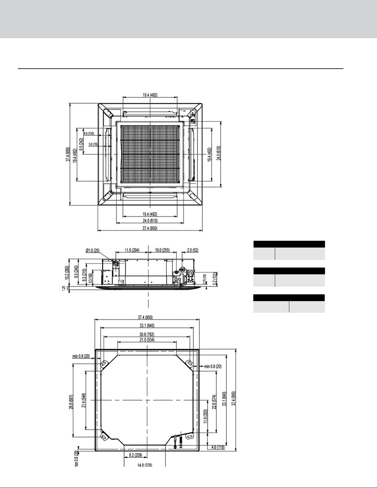
DIMENSIONAL SPECIFICATIONS
Model No: CAS24HP230V1AC 24,000 BtuH
Suction/Gas Line Port Size
Port 1 5/8-in OD Flared
Liquid Line Port Size
Port 1 3/8-in OD Flared
Drain Connector
Drain Line 1.2-in OD
50
Page 52

MINIMUM INDOOR CLEARANCE SPECIFICATIONS
The unit installation must meet or exceed the following minimum clearances for proper operation.
Ceiling
Installation stands for main body of the unit.
6.25-in
Above 0.75-in
Drainage hose
Refrigerant pipes
Air outlet vent
Pipe insulation
Air inlet grille
51
Page 53
+Multi Ceiling Cassettes
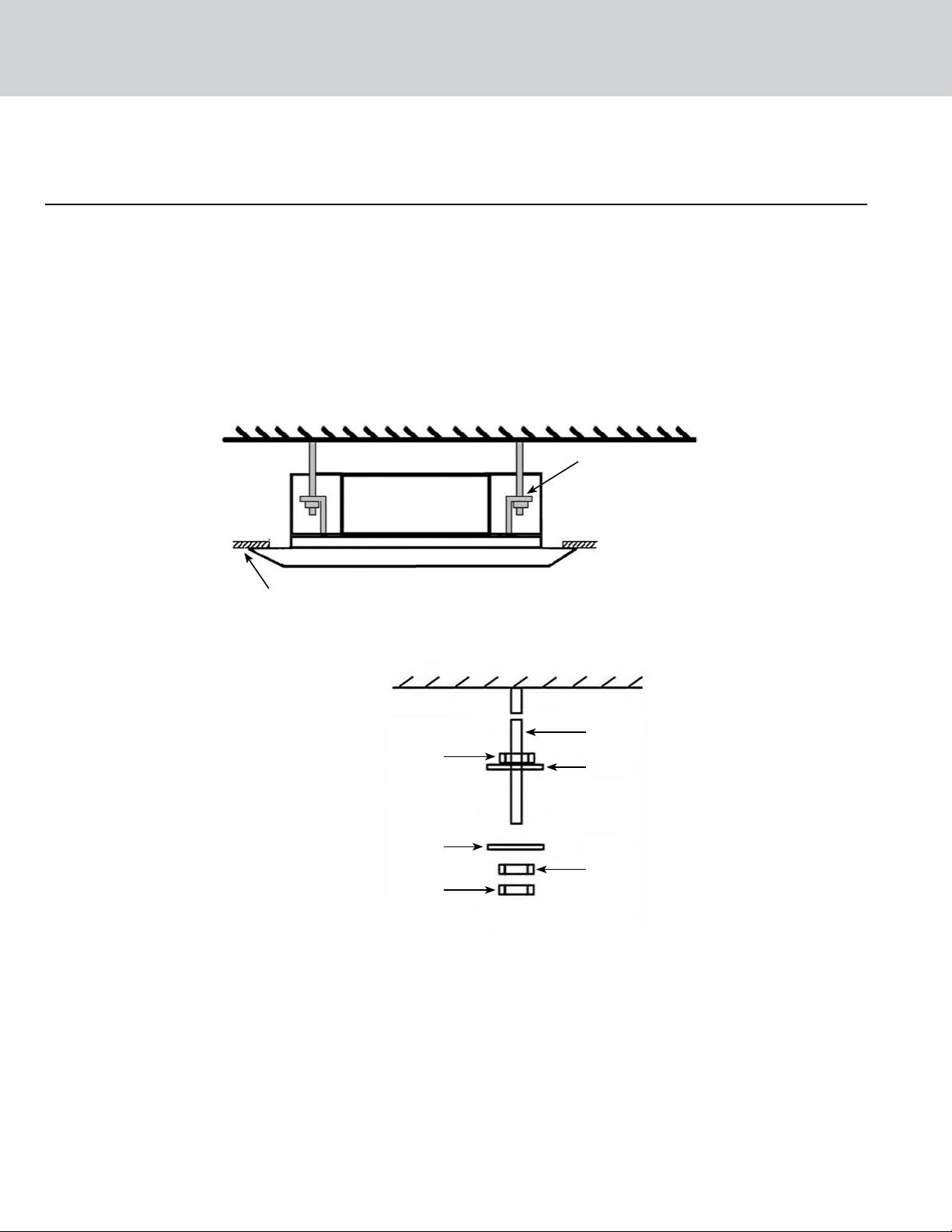
INSTALLATION OF MOUNTING HANGERS
Depending on the type of ceiling, threaded hanger bolts (field supplied) are recommended for securing
Ceiling Cassette to the ceiling or support studs.
Proper mounting hardware is critical which includes upper nuts, lower flat washers (with insulation), top
flat washers (without insulation), top nuts and locking nuts (double) on the threaded hanger bolts as show
in diagram below.
Mounting
Bracket
Ceiling
FPO
Nut
Washer
Nut
Threaded
Hanger Bolt
Washer
Nut
52
Page 54

CONDENSATE DRAIN DESIGNS
It’s recommended to build the condensate drain system with hard polyvinyl chloride (PVC) pipe and matching
connectors. Use pipe with either the same diameter or larger than the unit drainage port.
Gravity Drainage Systems with P-trap & Vent
Pitch the condensate drain pipes at a gradual 2.5%
pitch (Example: 1/4-in. drop over a 10-in. length)
without obstructions. Use pipe hanger/brackets to
support the condensate drain pipe from drooping.
Insulate all pipes to prevent sweating and water
damage.
Multiple Units with Common Drain
The following is the recommended condensate
drainage system for multiple units that share a
common drain line. Connecting multiple units to one
trap allows air to be pulled through one or more of
the units, bypassing the trap. An alternate method
is having individual drains and traps for each unit.
Ceiling
Hangers
Wall
Hanger
Wall
Ceiling
Wall
Vertical Lift Drainage System
If a gradual pitch from the drainage port is not
obtainable, the Ceiling Cassette contains an internal
condensate pump with limited head or lift. The
condensate drain pipe may have a vertical height of
11-in. (280 mm) maximum above the unit drainage
port within the first 12-in. (300 mm) as long as the
remaining condensate drain pipe gradually descends
from that point and aligns with drainage port.
Use an auxiliary condensate pump with float valve
for vertical height greater than 11-in. (280 mm) above
the unit drainage port. A float valve is recommended
to shut o the system if the auxiliary pump fails.
53
Ceiling
11-in
max
12-in
max
Hangers
Wall
Page 55

MULTI SLIM
CONCEALED DUCTS
Models:
DUCT09HP230V1AD
DUCT12HP230V1AD
DUCT18HP230V1AD
DUCT24HP230V1AD
Page 56

+Multi Slim Concealed Ducts
Table of Contents
Features and Benefits .........................56-57
Product Nomenclature ...........................58
Product Performance Data .....................58-61
Dimensional Specifications.....................62-64
Duct Design ....................................65
Sizing Specifications .............................66
Installation of Mounting Hangers...................66
Condensate Drain Designs ........................67
Page 57

+Multi Slim Concealed Ducts
Compact and powerful, the Gree Multi+ Concealed Duct indoor units oer the ultimate in flexibility and discretion. These slim indoor
units are designed to be concealed above suspended ceilings or within open closet spaces to deliver conditioned air via ducting and
suitable ceiling or wall grilles. This arrangement provides immense flexibility, in terms of both the distribution of conditioned air and the type
of grille or diuser that best complements the room’s styling. Each unit comes with an easy-to-operate wall mounted wired tether controller.
FEATURES AND BENEFITS
Whisper Quiet
Not only are the Gree systems energy ecient but they are quiet too. Wall mounted units operate
with sound levels starting as low as 31 dB(A).
Convenient Size (12K and 18K only)
The Gree ceiling cassettes can be easily mounted in a hard ceiling (with an access panel for servicing)
or in 2’x2’ drop ceiling. They provide great air distribution, quiet operation and a less obtrusive style.
Multi Fan Speeds
The indoor fan can run at up to three dierent speeds (Low, Medium or High) for either COOLING or
HEATING mode for maximum comfort and quiet operation.
Built In Condensate Lift Pump
The unit features a built-in drain pump that lifts condensation up to 11 inches above the drain pan to a
gravity condensate drain system. In most cases, the internal condensate lift mechanism will avoid the
need for an external condensate pump.
Condensate Sentry
The unit’s fail-safe mechanism recognizes when there is a high level in the condensate pan and shuts
o the system to prevent overflow problems.
Intelligent Pre-Heating
The Multi Zone system guards against the annoying COLD BLOW in heating mode. The system constantly
monitors the discharge air temperature. It will delay the indoor fan until the indoor coil has warmed
up to prevent blowing uncomfortable cool air into the room.
Tether Controller
The Gree wired tether controller mounts to the wall up to 25 feet from the unit. It provides complete
control over your unit’s operation mode, desired temperature, fan speed, airflow direction and more.
56
Page 58

FEATURES AND BENEFITS
Mode Button
The units can be set to five dierent operating modes: HEAT, COOL, DRY, FAN ONLY and AUTO.
Note: AUTO MODE has fixed setpoints of 68° F heating and 78° F cooling, which are not changeable.
The system will automatically select heating or cooling to maintain room temperature within this band.
Timer Mode
The unit can be programmed to turn ON or OFF after a specific amount of time. The time period is
adjustable between one half and 24 hours.
Sleep Mode
The unit will automatically adjust room temperature during your sleep time. This slight change in
temperature will not aect your comfort level due to the natural eects that sleeping has on the
body, but it will save on energy consumption and will lower electric bills.
Fahrenheit °F / Celsius °C
The wired tether controller can be set to display in either °F or °C.
Power Failure Mode
Power interruptions are no problem. User selections and system parameters are stored in non-volatile
memory. These parameters are retained during a power failure. When power is returned, the system
will automatically return to the last operating mode.
Self-Diagnosis
With an on-board computer using real-time diagnostics, the Gree Multi Zone system helps to prolong
its own life. The automatic diagnosis feature continuously scans for unacceptable operating conditions
or malfunctions. If such conditions occur, the system takes corrective action or stops. Fault codes are
shown on the unit display to facilitate easy troubleshooting and repair.
Privacy Lock Mode
The wired tether controller has a Privacy Lock. The Privacy Lock averts unauthorized access and stops
tampering with system settings.
Agency Listings
All systems are listed with AHRI (Air conditioning, Heating, and Refrigeration Institute) and are ETL
certified per UL Standards.
7/5 Year Limited Warranty
Enjoy one of the most comprehensive warranties in the industry. Seven (7) years on compressor
and Five (5) years on all parts.
57
Page 59

+Multi Slim Concealed Ducts
NOMENCLATURE
Series Designation
DUCT - Slim Duct Indoor Unit
MULTI - Multiple Port Outdoor Unit
NEO - Neo Indoor High Wall
CAS - Ceiling Cassette
FLR - Floor/Ceiling Unit
CONS - Mini Console
Cooling Capacity
9 - 9,000 BtuH
12 - 12,000 BtuH
18 - 18,000 BtuH
24 - 24,000 BtuH
Model Type
AC - Cooling Only
HP - Heat Pump
HC - Heat/Cool
DUCT 12 1 A D
HP 230V
Product Type
S - System
O - Outdoor Units
H - Indoor High Wall
D - Indoor Duct
C - Indoor Cassette
F - Indoor Floor/Ceiling
Revision Level
Style/Color Designation
Electrical Rating
230V - 208/230V 60Hz 1PH
115V - 115V 60Hz 1PH
PERFORMANCE SPECIFICATIONS AND DATA
Slim Concealed Duct
MODEL NUMBER
COOLING CAPACITY
(BtuH)
HEATING CAPACITY
(BtuH)
DEHUMIDIFICATION
(Pts./hr.)
DUCT09HP230V1AD 8,533 9,556 1.69
DUCT12HP230V1AD 11,946 13,140 2.96
DUCT18HP230V1AD 15,359 18,772 3.80
DUCT24HP230V1AD 24,232 27,304 5.28
Slim Concealed Duct
MODEL NUMBER
DUCT09HP230V1AD 147 177 265
DUCT12HP230V1AD 177 235 324
DUCT18HP230V1AD 294 353 412
DUCT24HP230V1AD 324 441 589
LOW FAN MEDIUM FAN HIGH FAN
COOLING (CFM)
Slim Concealed Duct
MODEL NUMBER
DUCT09HP230V1AD 147 177 265
DUCT12HP230V1AD 177 235 324
DUCT18HP230V1AD 294 353 412
LOW FAN MEDIUM FAN HIGH FAN
HEATING (CFM)
DUCT24HP230V1AD 324 441 589
58
Page 60

SOUND DATA
Slim Concealed Duct
LOW FAN
MODEL NUMBER
DUCT09HP230V1AD 41 31 44 34 47 37
DUCT12HP230V1AD 42 32 45 35 49 39
DUCT18HP230V1AD 43 33 47 37 51 41
DUCT24HP230V1AD 44 34 48 38 52 42
Note: 1. Sound pressure ratings are estimated sound pressure measurements, 3 feet from unit.
2. Sound power ratings are per AHRI 270 and AHRI 350
SOUND
POWER
SOUND
PRESSURE
MEDIUM FAN
SOUND
POWER
PRESSURE
SOUND
HIGH FAN
SOUND
POWER
SOUND
PRESSURE
ELECTRICAL DATA
Slim Concealed Duct
MODEL NUMBER
DUCT12HP230V1AD 208/230v-1ph-60hz 187-253 0.35 80
RATED POWER SUPPLY
(volt-phase-hz)
VOLTAGE RANGE
(volts)
RLA (amps) POWER (watts)
INDOOR FAN
DUCT12HP230V1AD 208/230v-1ph-60hz 187-253 0.35 80
DUCT18HP230V1AD 208/230v-1ph-60hz 187-253 0.43 100
DUCT24HP230V1AD 208/230v-1ph-60hz 187-253 0.54 124
Legend: RLA – Rated Load Amps
PRODUCT WEIGHT
Slim Concealed Duct
MODEL NUMBER
DUCT09HP230V1AD 49 lbs. 60 lbs.
DUCT12HP230V1AD 51 lbs. 64 lbs.
DUCT18HP230V1AD 60 lbs. 79 lbs.
DUCT24HP230V1AD 68 lbs. 90 lbs.
NET OPERATING GROSS SHIPPING
PRODUCT WEIGHT
59
Page 61
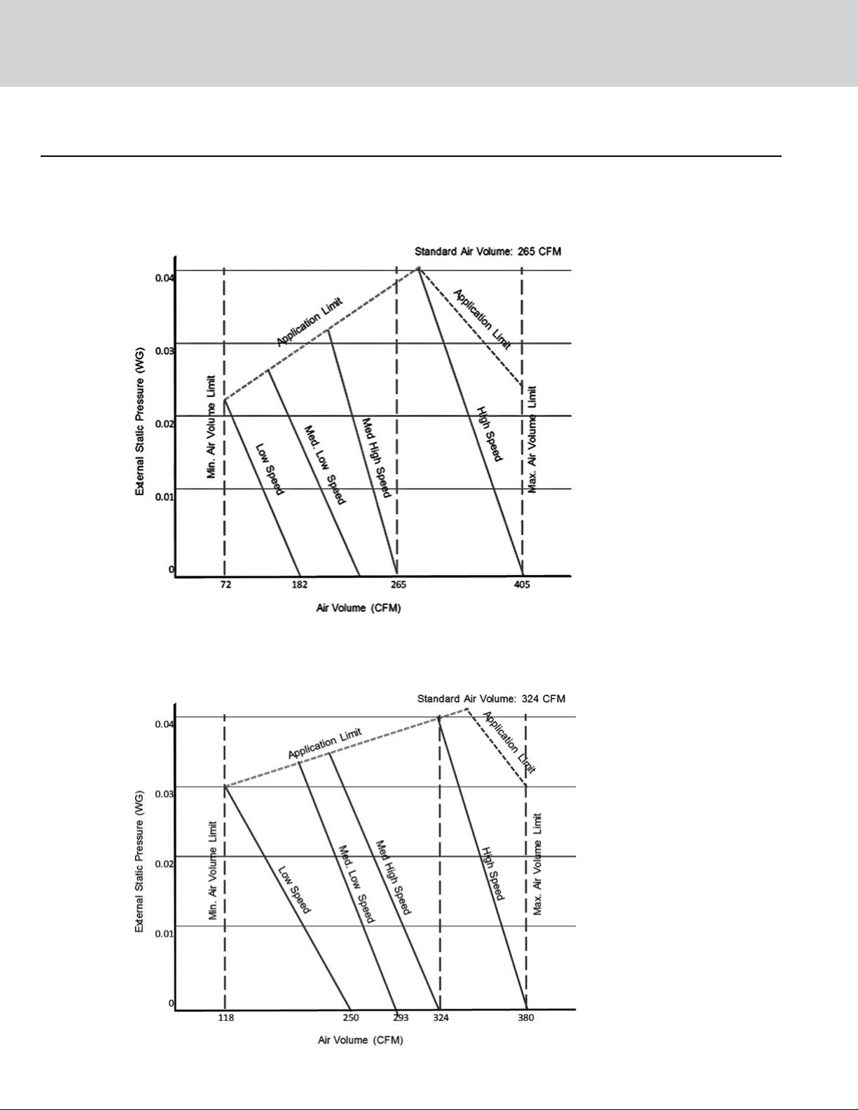
+Multi Slim Concealed Ducts
INDOOR FAN PERFORMANCE AND AIR FLOW
Model No: DUCT09HP230V1AD 9,000 BtuH
Model No: DUCT09HP230V1AD 9,000 BtuH
Model No: DUCT12HP230V1AD 12,000 BtuH
60
Page 62
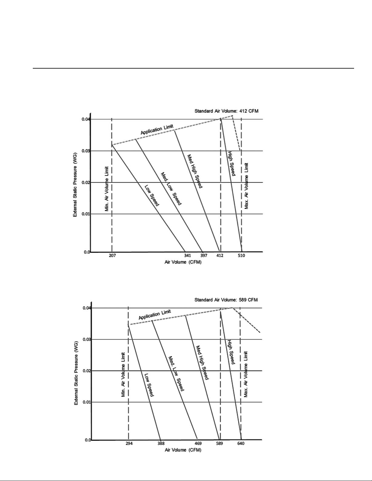
INDOOR FAN PERFORMANCE AND AIR FLOW
Model No: DUCT18HP230V1AD 18,000 BtuH
Model No: DUCT24HP230V1AD 24,000 BtuH
61
Page 63
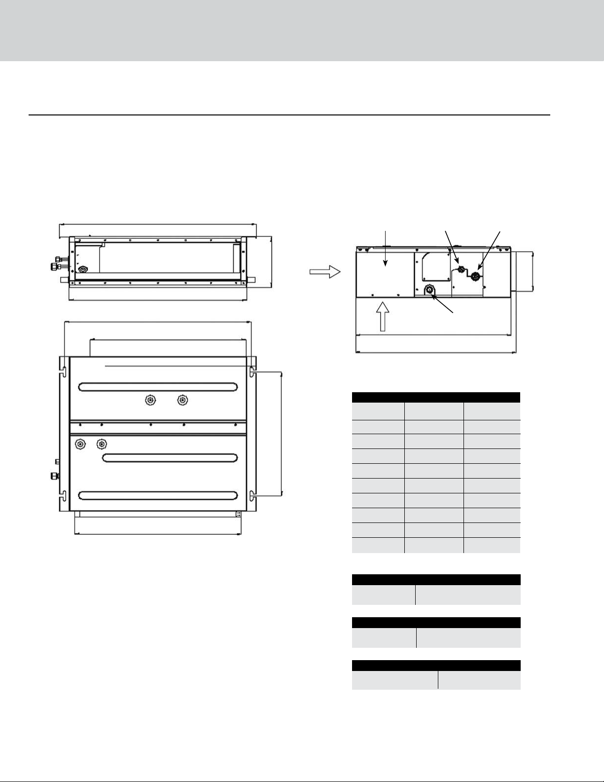
+Multi Slim Concealed Ducts
DIMENSIONAL SPECIFICATIONS
Model No: DUCT09HP230V1AD 9,000 BtuH
Model No: DUCT12HP230V1AD 12,000 BtuH
G
Side
I
E
A
D
B
C
Return Air
Electric Box
Return Air
Dimension (mm) (inches)
A 742 29.2
B 491 19.3
C 662 26.1
D 620 24.4
E 700 27.6
F 615 24.2
G 782 30.8
H 156 6.1
I 200 7.9
J 635 25.0
Liquid Pipe Gas Pipe
Bottom
F
J
Drain Pipe
H
Suction/Gas Line Port Size
Port 1 3/8-in OD Flared
Liquid Line Port Size
Port 1 1/4-in OD Flared
Drain Connector
Drain Line 1.0-in OD
evaporator port sizes.
Note: Size refrigerant lines based on
62
Page 64

DIMENSIONAL SPECIFICATIONS
Model No: DUCT18HP230V1AD 18,000 BtuH
G
Side
I
Return Air
Electric Box
Liquid Pipe Gas Pipe
H
E
A
Bottom
Return Air
D
Drain Pipe
F
J
Dimension (mm) (inches)
A 942 37.1
B
C
B 491 19.3
C 862 33.9
D 820 32.3
E 900 35.4
F 615 24.2
G 982 38.7
H 156 6.1
I 200 7.9
J 635 25.0
63
Suction/Gas Line Port Size
Port 1 1/2-in OD Flared
Liquid Line Port Size
Port 1 1/4-in OD Flared
Drain Connector
Drain Line 1.0-in OD
Note: Size refrigerant lines based on
evaporator port sizes.
Page 65

+Multi Slim Concealed Ducts
DIMENSIONAL SPECIFICATIONS
Model No: DUCT24HP230V1AD 24,000 BtuH
G
Side
I
E
A
D
B
C
Return Air
Electric Box
Return Air
Dimension (mm) (inches)
A 1124 44.3
B 491 19.3
C 1062 41.8
D 1020 40.2
E 1100 43.3
F 615 24.2
G 1182 46.5
H 156 6.1
I 200 7.9
J 635 25.0
Liquid Pipe Gas Pipe
Bottom
F
J
Drain Pipe
H
Suction/Gas Line Port Size
Port 1 5/8-in OD Flared
Liquid Line Port Size
Port 1 3/8-in OD Flared
Drain Connector
Drain Line 1.0-in OD
evaporator port sizes.
Note: Size refrigerant lines based on
64
Page 66

DUCT DESIGN
Return Air
Option 1 Return Air
Concealed Duct
Option 2
Supply
Air
Typical Ductwork Layout
Back Return Air
Downward Air
Return
Return Air
Cover Plate
Rectangular Flange
65
Page 67

+Multi Slim Concealed Ducts
DUCT SIZING SPECIFICATIONS
E
D
A
B
C
Dimensions
SUPPLY DUCT
MODEL NUMBER
(in/mm)
A B
DUCT09P230V1AD 6.1/156 26.1/662 22.8/580 6.4/162 0.8/21
DUCT12P230V1AD 6.1/156 26.1/662 22.8/580 6.4/162 0.8/21
DUCT18P230V1AD 6.1/156 33.9/862 30.7/780 6.4/162 0.8/21
DUCT24P230V1AD 6.1/156 41.8/1062 38.6/980 6.4/162 0.8/21
RETURN DUCT
(in/mm)
C D
FLANGE
(in/mm)
E
INSTALLATION OF MOUNTING HANGERS
Depending on the type of ceiling, threaded hanger bolts (field supplied) are recommended for securing the
Concealed Duct to the ceiling or support studs.
Proper mounting hardware is critical, which includes upper nuts, lower flat washers (with insulation), top flat
washers (without insulation), top nuts and locking nuts (double) on the threaded hanger bolts as show in
diagram below.
66
Nut
Washer
Nut
Threaded
Hanger Bolt
Washer
Nut
Page 68

CONDENSATE DRAIN DESIGNS
It’s recommended to build the condensate drain system with hard polyvinyl chloride (PVC) pipe and matching
connectors. Use pipe with either the same diameter or larger than the unit drainage port.
Gravity Drainage Systems
with P-trap & Vent
Pitch the condensate drain pipes at a gradual
2.5% pitch (Example: 1/4-in. drop over a 10-in.
length) without obstructions. Use pipe hanger/
brackets to support the condensate drain pipe
from drooping. Insulate all pipes to prevent
sweating and water damage.
Multiple Units with Common Drain
Ceiling
Ceiling
Hangers
Wall
Hangers
Wall
Ceiling
The following is the recommended condensate
drainage system for multiple units that share a
common drain line. Connecting multiple units
to one trap allows air to be pulled through one
or more of the units, bypassing the trap. An
alternate method is having individual drains
and traps for each unit.
Vertical Lift Drainage System
If a gradual pitch from the drainage port is not
obtainable, the Concealed Duct contains an
internal condensate pump with limited head or
lift. The condensate drain pipe may have a
vertical height of 11-in. (280 mm) maximum
above the unit drainage port within the first
12-in. (300 mm) as long as the remaining
condensate drain pipe gradually descends
from that point and aligns with drainage port.
Use an auxiliary condensate pump with float
valve for vertical height greater than 11-in.
(280 mm) above the unit drainage port. A float
valve is recommended to shut o the system
if the auxiliary pump fails.
Ceiling
11-in
max
12-in
max
Wall
Hangers
Wall
67
Page 69

MULTI UNIVERSAL
FLOOR/CEILING
Models:
FLR09HP230V1AF
FLR12HP230V1AF
FLR18HP230V1AF
FLR24HP230V1AF
Page 70

+Multi Universal Floor/Ceiling
Table of Contents
Features and Benefits .........................70-72
Product Nomenclature ...........................72
Product Performance Data .....................73 -74
Dimensional Specifications........................75
Clearance Specifications..........................76
Installation of Mounting Hangers...................77
Page 71

+Multi Universal Floor/Ceiling
Our Multi+ Universal Floor/Ceiling indoor units are designed to be suspended from a ceiling or mounted low on a wall. The slender and
lightweight design is perfect for restaurants or hallways where wall space is limited. Aesthetically pleasing to the eye, the Multi+ Universal
Floor/Ceiling units are a great fit beneath windows, in public or light commercial applications. Each unit can be operated by an infrared
remote controller or wired tether controller to allow maximum flexibility in any application.
FEATURES AND BENEFITS
Whisper Quiet
Not only are the Gree systems energy ecient but they are quiet too. Wall mounted units operate
with sound levels starting as low as 36 dB(A).
Modern Appearance
Designed to be a comfortable fit in virtually any living space. This slim compact cabinet sits
inconspicuously on the wall, and blends into most interior designs.
Unit Display
Gree wall mounted units have a large easy to read display and indicator lights giving instant feedback
on room setpoint, operating mode and much more. The display can also be turned o based on your
personal preference.
Multi Fan Speeds
The indoor fan can run at up to three dierent speeds (Low, Medium or High) for either COOLING or
HEATING mode for maximum comfort and quiet operation.
Time Guard
The Multi Zone system is equipped with many system safeties to provide safe, reliable operation and
comfort. The Time Guard function prevents rapid cycling of the compressor. The system has a protective
five-minute time delay to restart the compressor after it has turned o.
Power Failure Mode
Power interruptions are no problem. User selections and system parameters are stored in non-volatile
memory. These parameters are retained during a power failure. When power is returned, the system
will automatically return to the last operating mode.
Intelligent Pre-Heating
The Multi Zone system guards against the annoying COLD BLOW in heating mode. The system constantly
monitors the discharge air temperature. It will delay the indoor fan until the indoor coil has warmed
up to prevent blowing uncomfortable cool air into the room.
70
Page 72

FEATURES AND BENEFITS
Controller
The unit comes with a factory supplied wired Tether Controller or Wireless Remote Controller.
Note: the controllers are mutually exclusive. They cannot be used at the same time.
IR Wireless Remote Controller
The Gree multi-functional infrared hand held wireless controller is sleek, ergonomically
designed, easy to use and has a large backlit LCD display.
Tether Controller
The Gree tether controller mounts to the wall up to 25 feet from the unit. It provides complete
control over operation mode, desired temperature, fan speed, airflow direction and more.
Mode Button
The units can be set to five dierent operating modes: HEAT, COOL, DRY, FAN ONLY and AUTO.
Note: AUTO MODE has fixed setpoints of 68° F heating and 78° F cooling, which are not changeable.
The system will automatically select heating or cooling to maintain room temperature within this band.
Timer Mode
The unit can be programmed to turn ON or OFF after a specific amount time. The time period is
adjustable between one half and 24 hours.
Swing Louver
The unit has adjustable swing louvers which can be controlled from the wired tether or wireless
controllers. Vertical swing louver allows five dierent vertical (up & down) air discharge directions
including Continuous Sweep. Maximize comfort by adjusting the direction of airflow in the room by
moving the louvers up or down.
Privacy Lock Mode
Both wired tether and wireless controllers have a Privacy Lock to avert unauthorized access and stop
tampering with system settings.
Sleep Mode
The unit will automatically adjust room temperature during sleep time. This slight change in
temperature will not aect your comfort level due to the natural eects that sleeping has on the
body, but it will save on energy consumption and will lower electric bills.
Fahrenheit °F / Celsius °C
The wired tether and wireless controllers can be set to display in either °F or °C.
Easy To Clean Air Filter
A removable air filter easily slides in and out from the front of the indoor unit. The front panel does
not need to be removed to access or change the filter. The filter is washable and permanent.
71
Page 73
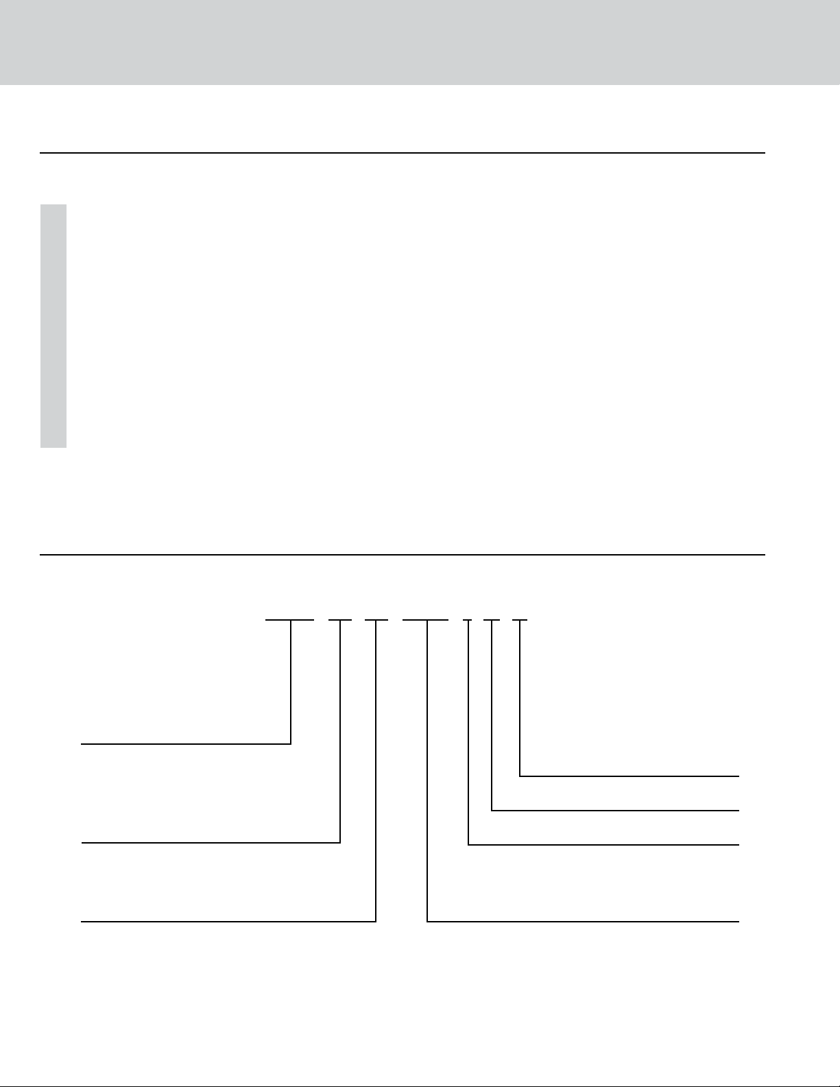
+Multi Universal Floor/Ceiling
FEATURES AND BENEFITS
Self-Diagnosis
With an on-board computer using real-time diagnostics, the Gree Multi Zone system helps to
prolong its own life. The automatic diagnosis feature continuously scans for unacceptable operating
conditions or malfunctions. If such conditions occur, the system takes corrective action or stops.
Fault codes are shown on the unit display to facilitate easy troubleshooting and repair.
Agency Listings
All systems are listed with AHRI (Air conditioning, Heating, and Refrigeration Institute) and are ETL
certified per UL Standards.
7/5 Year Limited Warranty
Enjoy one of the most comprehensive warranties in the industry. Seven (7) years on compressor
and Five (5) years on all parts.
NOMENCLATURE
Series Designation
FLR - Floor/Ceiling Unit
MULTI - Multiple Port Outdoor Unit
DUCT - Slim Duct Indoor Unit
CAS - Ceiling Cassette
NEO - Neo Indoor High Wall
CONS - Mini Console
Cooling Capacity
9 - 9,000 BtuH
12 - 12,000 BtuH
18 - 18,000 BtuH
24 - 24,000 BtuH
Model Type
AC - Cooling Only
HP - Heat Pump
HC - Heat/Cool
FLR 12 1 A F
HP 230V
Product Type
S - System
O - Outdoor Units
H - Indoor High Wall
D - Indoor Duct
C - Indoor Cassette
F - Indoor Floor/Ceiling
Revision Level
Style/Color Designation
Electrical Rating
230V - 208/230V 60Hz 1PH
115V - 115V 60Hz 1PH
72
Page 74

PERFORMANCE SPECIFICATIONS & DATA
Universal Floor/Ceiling
MODEL NUMBER
FLR09HP230V1AF 8,533 9,556 1.7
FLR12HP230V1AF 11,946 13,140 3.0
FLR18HP230V1AF 17,065 18,772 3.8
FLR24HP230V1AF 22,867 27,304 5.1
COOLING CAPACITY
(BtuH)
HEATING CAPACITY
(BtuH)
DEHUMIDIFICATION
(Pts./hr.)
Universal Floor/Ceiling
MODEL NUMBER AIR FILTER TYPE AIR FLOW FAN TYPE
FLR09HP230V1AF Polymeric Mesh 4-way Centrifugal
FLR12HP230V1AF Polymeric Mesh 4-way Centrifugal
FLR18HP230V1AF Polymeric Mesh 4-way Centrifugal
FLR24HP230V1AF Polymeric Mesh 4-way Centrifugal
Universal Floor/Ceiling
MODEL NUMBER
FLR09HP230V1AF 265 324 383 265 324 383
FLR12HP230V1AF 265 324 383 265 324 383
FLR18HP230V1AF 294 412 559 294 412 559
FLR24HP230V1AF 412 530 736 412 530 736
COOLING (CFM) HEATING (CFM)
LOW
FAN
MEDIUM
FAN
HIGH
FAN
LOW
FAN
MEDIUM
FAN
HIGH
FAN
73
Page 75

+Multi Universal Floor/Ceiling
SOUND DATA
Universal Floor/Ceiling
LOW FAN
MODEL NUMBER
FLR09HP230V1AF 46 dBA 36 dBA 48 dBA 38 dBA 50 dBA 40 dBA
FLR12HP230V1AF 46 dBA 36 dBA 48 dBA 38 dBA 50 dBA 40 dBA
FLR18HP230V1AF 50 dBA 40 dBA 52 dBA 42 dBA 55 dBA 45 dBA
FLR24HP230V1AF 54 dBA 44 dBA 56 dBA 46 dBA 58 dBA 48 dBA
Note: 1. Sound pressure ratings are estimated sound pressure measurements, 3 feet from unit.
2. Sound power ratings are per AHRI 270 and AHRI 350
SOUND
POWER
SOUND
PRESSURE
MEDIUM FAN
SOUND
POWER
PRESSURE
SOUND
HIGH FAN
SOUND
POWER
SOUND
PRESSURE
ELECTRICAL DATA
Universal Floor/Ceiling
MODEL NUMBER
FLR09HP230V1AF 208/230v-1ph-60hz 187-253 0.30 55
RATED POWER SUPPLY
(volt-phase-hz)
VOLTAGE RANGE
(volts)
RLA (amps) POWER (watts)
INDOOR FAN
FLR12HP230V1AF 208/230v-1ph-60hz 187-253 0.30 55
FLR18HP230V1AF 208/230v-1ph-60hz 187-253 0.60 110
FLR24HP230V1AF 208/230v-1ph-60hz 187-253 0.60 145
Legend: RLA – Rated Load Amps
PRODUCT WEIGHT
Universal Floor/Ceiling
MODEL NUMBER
FLR09HP230V1AF 88 lbs. 110 lbs.
FLR12HP230V1AF 88 lbs. 110 lbs.
FLR18HP230V1AF 88 lbs. 110 lbs.
FLR24HP230V1AF 100 lbs. 120 lbs.
NET OPERATING GROSS SHIPPING
PRODUCT WEIGHT
74
Page 76

DIMENSIONAL SPECIFICATIONS
H
A
C
B
D
Dimensions
MODEL NUMBER
FLR09HP230V1AF 48/1220 8.9/225 45.6/1158 11/280 27.6/700
FLR12HP230V1AF 48/1220 8.9/225 45.6/1158 11/280 27.6/700
A B
C D
H
FLR18HP230V1AF 48/1220 8.9/225 45.6/1158 11/280 27.6/700
FLR24HP230V1AF 48/1220 8.9/225 45.6/1158 11/280 27.6/700
MODEL NUMBER
FLR09HP230V1AF 1/4-in OD Flared 0.67in/17mm OD
FLR12HP230V1AF 1/4-in OD Flared 0.67in/17mm OD
FLR18HP230V1AF 1/4-in OD Flared 0.67in/17mm OD
FLR24HP230V1AF
Note: Size refrigerant lines based on evaporator port sizes.
SUCTION/GAS LINE
PORT SIZE
3/8-in OD Flared
3/8-in OD Flared
1/2-in OD Flared
/8-in OD Flared
5
75
LIQUID LINE
PORT SIZE
3/8-in OD Flared 0.67in/17mm OD
DRAIN
CONNECTOR
Page 77

+Multi Universal Floor/Ceiling
MINIMUM INDOOR CLEARANCE SPECIFICATIONS
The unit installation must meet or exceed the following minimum clearances for proper operation.
> 5ft
> 2ft
> 2ft
> 1ft
> 9-in
> 7.5ft
> 2ft
> 2ft
> 3ft
> 5ft
> 1ft
76
Page 78
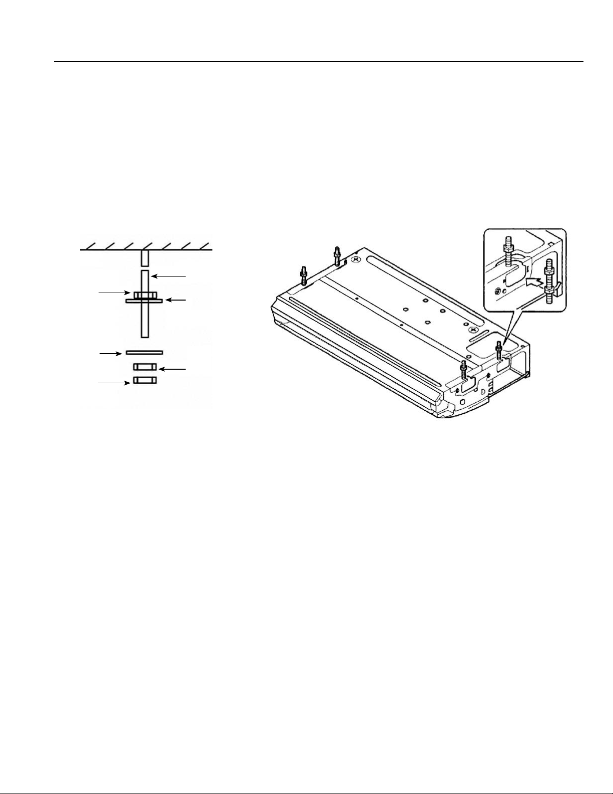
INSTALLATION OF MOUNTING HANGER
Depending on the type of ceiling, threaded hanger bolts (field supplied) are recommended for securing
Floor/Ceiling unit to the ceiling or support studs.
Proper mounting hardware is critical which includes upper nuts, lower flat washers (with insulation),
top flat washers (without insulation), top nuts and locking nuts (double) on the threaded hanger bolts
as shown in diagram below.
Threaded
Hanger Bolt
Nut
Washer
Washer
Nut
Nut
77
Page 79
MULTI MINI-FLOOR
CONSOLES
Models:
CONS09HP230V1AF
CONS12HP230V1AF
CONS18HP230V1AF
Page 80

+Multi Mini-Floor Consoles
Table of Contents
Features and Benefits .........................80-81
Product Nomenclature ...........................82
Clearance Specifications..........................82
Product Performance Data .....................83-84
Dimensional Specifications........................85
Page 81

+Multi Mini-Floor Consoles
Gree’s +Multi Mini Console indoor units are aesthetically pleasing and the perfect size for any room. The space saving design provides
energy ecient solutions for dicult areas that may not have abundant space on the ceiling or walls. It can be mounted as low as six
inches above the floor and has front panel access to the filter for ease of cleaning. Each +Multi Mini Console unit can be operated by
an infrared remote controller.
FEATURES AND BENEFITS
Whisper Quiet
Gree systems are energy ecient and quiet. Wall mounted units operate with sound levels starting
as low as 25 dB(A).
Modern Appearance
Designed to be a comfortable fit in virtually any living space. This slim compact cabinet sits
inconspicuously on the wall, and blends into most interior designs.
Unit Display
Gree wall mounted units have a large, easy-to-read display and indicator lights giving instant feedback
on room setpoint, operating mode and much more. The display can also be turned o based on your
personal preference.
Multi-Speed Fan
The indoor fan can run at up to four dierent speeds (Low, Medium, High or Turbo) for either
COOLING or HEATING mode for maximum comfort and quiet operation.
Time Guard
Among the system’s many safeties is a Time Guard function to prevent rapid cycling of the compressor.
A protective five-minute time delay restricts compressor restarts after shuto.
Power Failure Mode
Power interruptions are no problem. User selections and system parameters are stored in non-volatile
memory. These parameters are retained during a power failure. When power is returned, the system
will automatically return to the last operating mode.
Intelligent Pre-Heating
The Multi Zone system guards against the annoying COLD BLOW in heating mode, and constantly
monitors the discharge air temperature. It will delay the indoor fan until the indoor coil has warmed
up to prevent blowing uncomfortable cool air into the room.
IR Wireless Remote Controller
The Gree Multi-functional infrared hand held wireless controller is sleek, ergonomically designed,
easy to use and has a large backlit LCD display.
80
Page 82

FEATURES AND BENEFITS
Mode Button
The units can be set to five dierent operating modes: HEAT, COOL, DRY, FAN ONLY and AUTO.
Note: AUTO MODE has fixed setpoints of 68° F heating and 78° F cooling, which are not changeable.
The system will automatically select heating or cooling to maintain room temperature within this band.
Timer Mode
The unit can be programmed to turn ON or OFF after a specific amount time. The time period
is adjustable between one half and 24 hours.
Swing Louver
The unit has adjustable swing louvers which can be controlled from the wireless controller. Vertical
swing louver allows five dierent vertical (up & down) air discharge directions including Continuous
Sweep. Maximize comfort by adjusting the direction of airflow in the room by moving the louvers
up or down.
Privacy Lock Mode
The wireless controller has a Privacy Lock to avert unauthorized access and stop tampering with
system settings.
Sleep Mode
The unit will automatically adjust room temperature during sleep time. This slight change in
temperature will not aect your comfort level due to the natural eects that sleeping has on the
body, but it will save on energy consumption and will lower electric bills.
Fahrenheit °F / Celsius °C
The wireless controller can be set to display in either °F or °C.
Easy To Clean Air Filters
Removable air filters easily slide in and out from the front of the indoor unit. The front panel does
not need to be removed to access or change the filter. The filters are washable and permanent.
Self-Diagnosis
With an on-board computer using real-time diagnostics, the Gree Multi Zone system helps to
prolong its own life. The automatic diagnosis feature continuously scans for unacceptable operating
conditions or malfunctions. If such conditions occur, the system takes corrective action or stops.
Fault codes are shown on the unit display to facilitate easy troubleshooting and repair.
Agency Listings
All systems are listed with AHRI (Air conditioning, Heating, and Refrigeration Institute) and are
ETL Certified per UL Standards.
7/5 Year Limited Warranty
Enjoy one of the most comprehensive warranties in the industry. Seven (7) years on compressor
and Five (5) years on all parts.
81
Page 83

+Multi Mini-Floor Consoles
NOMENCLATURE
CONS 12 1 A F
Series Designation
NEO - Neo Indoor High Wall
MULTI - Multiple Port Outdoor Unit
DUCT - Slim Duct Indoor Unit
CAS - Ceiling Cassette
FLR - Floor/Ceiling Unit
CONS - Mini Console
Cooling Capacity
9 - 9,000 BtuH
12 - 12,000 BtuH
18 - 18,000 BtuH
Model Type
AC - Cooling Only
HP - Heat Pump
HC - Heat/Cool
HP 230V
Product Type
S - System
O - Outdoor Units
H - Indoor High Wall
D - Indoor Duct
C - Indoor Cassette
F - Indoor Floor/Ceiling
Revision Level
Style/Color Designation
Electrical Rating
230V - 208/230V 60Hz 1PH
115V - 115V 60Hz 1PH
MINIMUM INDOOR CLEARANCE SPECIFICATIONS
The unit installation must meet or exceed the following minimum clearances for proper operation.
A
Dimension (inches) (mm)
A 59 1500
B 59 1500
C 6 150
D
C
B
D 59 1500
82
Page 84

PERFORMANCE SPECIFICATIONS & DATA
Mini-Floor Console
MODEL NUMBER
CONS09HP230V1AF 8,874 9,556 1.7
CONS12HP230V1AF 11,946 12,969 3.0
CONS18HP230V1AF 18,089 19,795 3.8
COOLING CAPACITY
(BtuH)
HEATING CAPACITY
(BtuH)
DEHUMIDIFICATION
(Pts./hr.)
Mini-Floor Console
MODEL NUMBER AIR FILTER TYPE AIR FLOW FAN TYPE
CONS09HP230V1AF Polymeric Mesh 4-way Centrifugal
CONS12HP230V1AF Polymeric Mesh 4-way Centrifugal
CONS18HP230V1AF Polymeric Mesh 4-way Centrifugal
Mini-Floor Console
MODEL NUMBER
CONS09HP230V1AF 147 165 194 241 253 294
LOW
FAN
MEDIUM
1 FAN
COOLING (CFM)
MEDIUM
2 FAN
MEDIUM
3 FAN
MEDIUM
4 FAN
HIGH
FAN
CONS12HP230V1AF 165 212 235 283 306 353
CONS18HP230V1AF 188 241 265 324 365 383
Mini-Floor Console
MODEL NUMBER
CONS09HP230V1AF 147 165 194 241 253 294
CONS12HP230V1AF 165 212 235 283 306 353
CONS18HP230V1AF 188 241 265 324 365 383
LOW
FAN
MEDIUM
1 FAN
HEATING (CFM)
MEDIUM
2 FAN
MEDIUM
3 FAN
MEDIUM
4 FAN
AIR THROW DATA
Mini-Floor Console
MODEL NUMBER
LOW
FAN
MEDIUM
1 FAN
HEATING (CFM)
MEDIUM
2 FAN
MEDIUM
3 FAN
MEDIUM
4 FAN
HIGH
FAN
HIGH
FAN
CONS09HP230V1AF 2.0 3.6 2.9 3.6 3.9 4.5
CONS12HP230V1AF 2.5 3.1 3.4 4.1 4.6 5.0
CONS18HP230V1AF 3.0 3.4 4.1 4.4 5.1 5.5
83
Page 85

+Multi Mini-Floor Consoles
SOUND DATA
Mini-Floor Console – Sound Pressure
MODEL NUMBER
CONS09HP230V1AF 25 dBA 26 dBA 30dBA 36 dBA 38 dBA 40 dBA
CONS12HP230V1AF 27 dBA 32 dBA 35 dBA 38 dBA 40 dBA 43 dBA
CONS18HP230V1AF 33 dBA 35 dBA 37 dBA 44 dBA 46 dBA 48 dBA
LOW
FAN
MEDIUM
1 FAN
MEDIUM
2 FAN
MEDIUM
3 FAN
MEDIUM
4 FAN
HIGH
FAN
Mini-Floor Console – Sound Power
MODEL NUMBER
CONS09HP230V1AF 35 dBA 36 dBA 40dBA 46 dBA 48 dBA 50 dBA
CONS12HP230V1AF 37 dBA 42 dBA 45 dBA 48 dBA 50 dBA 53 dBA
CONS18HP230V1AF 43 dBA 45 dBA 47 dBA 54 dBA 56 dBA 58 dBA
Note: 1. Sound pressure ratings are estimated sound pressure measurements, 3 feet from unit.
2. Sound power ratings are per AHRI 270 and AHRI 350.
LOW
FAN
MEDIUM
1 FAN
MEDIUM
2 FAN
MEDIUM
3 FAN
MEDIUM
4 FAN
HIGH
FAN
ELECTRICAL DATA
Mini-Floor Console
MODEL NUMBER
CONS09HP230V1AF 208/230v-1ph-60hz 187-253 0.3 30.0
CONS12HP230V1AF 208/230v-1ph-60hz 187-253 0.3 30.0
CONS18HP230V1AF 208/230v-1ph-60hz 187-253 0.3 30.0
Legend: RLA – Rated Load Amps
RATED POWER SUPPLY
(volt-phase-hz)
VOLTAGE RANGE
(volts)
RLA (amps) POWER (watts)
INDOOR FAN
PRODUCT WEIGHT
Mini-Floor Console
MODEL NUMBER
CONS09HP230V1AF 30 lbs. 40 lbs.
CONS12HP230V1AF 30 lbs. 40 lbs.
CONS18HP230V1AF 30 lbs. 40 lbs.
NET OPERATING GROSS SHIPPING
PRODUCT WEIGHT
84
Page 86

DIMENSIONAL SPECIFICATIONS
A
H
B
MODEL NUMBER
C
SUCTION/GAS LINE
PORT SIZE
Dimension (inches) (mm)
A 27.6 700
B 8.5 215
C 7.875 200
H 23.6 600
LIQUID LINE
PORT SIZE
DRAIN
CONNECTOR
CONS09HP230V1AF 3/8-in OD Flared 1/4-in OD Flared 0.67in/17mm OD
CONS12HP230V1AF 3/8-in OD Flared 1/4-in OD Flared 0.67in/17mm OD
CONS18HP230V1AF 1/2-in OD Flared 1/4-in OD Flared 0.67in/17mm OD
Note: Size refrigerant lines based on evaporator port sizes.
85
Page 87
WIRED TETHER
CONTROLLER
Part Numbers:
MC20700140 - XK-19
MC207059 - XK-41
Page 88

Wired Tether Controller
Table of Contents
Reference Table .................................88
Features and Benefits .........................88-89
Dimensional Specifications....................... 90
System Wiring Diagram.......................... 90
Installation .....................................91
Limited Warranty Statement ...................92-93
Page 89

Wired Tether Controller
REFERENCE TABLE
INDOOR UNIT
NEO WALL MOUNT XK-41 MC207059
CEILING CASSETTE XK-19 MC207001140
SLIM CONCEALED DUCT XK-19 MC207001140
UNIVERSAL FLOOR CEILING XK-19 MC207001140
MINI-FLOOR CONSOLE XK-19 MC207001140
TYPE PART NUMBER
TETHER CONTROLLER
FEATURES AND BENEFITS
Attractive Appearance
The XK series features a sleek, unobtrusive design that fits seamlessly into any décor.
Easy To Install
The XK series Wired Tether Controllers have been designed for fast and easy installation to save you
time and money. Each XK wired controller comes with keyed connectors and 26 feet of cable. Its
flexible design allows it to be mounted either flush to the wall or using an electrical box.
Command Center
Enjoy the convenience of a fully functional command center with a large LCD display to set up and
operate your duct free system. The XK series allows you fast and easy access to a large number of
system features and functions:
Note: Some indoor units may not support specific system features or functions. Always refer to the
indoor unit Owner’s Manual.
On/O
The XK series allows you to start and stop your system. The system will always start up in the
last operating mode with the last room setpoint.
Operating Mode
The system allows users to eortlessly select an operating mode (Cooling, Heating, Dry,
Fan Only or Auto mode) with a single key stroke.
88
Page 90

FEATURES AND BENEFITS
Command Center (cont.)
Fan Speed
The system fan speed (High, Medium, Low or Auto) can be adjusted for peak room comfort
and quietness.
Room Setpoint
The XK series makes dialing in the correct room setpoint temperature a breeze. Most indoor
units allow a room setpoint from 61° F to 86° F (16° to 30° C).
Timer Mode
When needed, the XK series allows you the ability to program a time period (one-half to
24 hours) to which your system will automatically turn ON or OFF.
Sleep Mode
The XK series will automatically adjust room temperature during your sleep time. This slight
change in temperature will not aect your comfort level due to the natural eects that
sleeping has on the body, but it will save on energy consumption and will lower electric bills.
Turbo Mode
Whether you need to heat up or cool down a room quickly, Turbo Mode will force your system
to run at higher speeds to reach the desired room temperature faster.
X-Fan Mode
The X-Fan function can be activated from the XK series to remove moisture buildup when the
system is turned OFF. This helps prevent mold and mildew growth on your indoor coil and fan.
Privacy Lock
The XK series has a Privacy Lock that can be set to prevent unauthorized access to the unit
controls and prevents tampering with system settings.
Power Failure Recovery
Power interruptions are no problem for the XK series wired controller. All user selections and
system parameters are stored in non-volatile memory. When power is returned, the system
will automatically return to the last operating mode.
Swing Louver Control
The XK series provides control over the motorized discharge air louver to optimize air distribution
throughout the room.
Fahrenheit or Celsius Display
Whether you are more comfortable reading temperatures in Fahrenheit or Celsius, the
XK series can quickly be set up to display either one.
Diagnostic Center
The system has an on-board computer that continuously scans for unacceptable operating
conditions or malfunctions. If such conditions occur, the system takes corrective action or
stops. The fault or status codes will be shown on XK series wired tether controller display
to facilitate easy troubleshooting and repair.
89
Page 91

Wired Tether Controller
DIMENSIONAL SPECIFICATIONS
A C
B B
TYPE PART NUMBER
XK-41 MC207059 3.625 (92) 3.625 (92) 1.375 (35)
XK-19 MC207001140 3.625 (92) 3.625 (92) 1.375 (35)
A
in (mm)
B
in (mm)
C
in (mm)
SYSTEM WIRING DIAGRAM
90
Page 92

INSTALLATION
The following is a brief XK-19 and XK-41 Wired Tether
Controller installation overview. See Wired Controller
Installation Manual for more detailed instructions on
installation, start-up, and setup.
Connecting Indoor Unit
Select a proper location on the wall for mounting
the Tether Controller. Install switch box, if required
by code. Locate the 26-ft communication cable that
came with the Tether Controller. Run communication
cable (as desired) between indoor unit and selected
wall mounting location. Locate the Tether Controller
connector in the control box area of the indoor unit.
Carefully connect communication cable to indoor unit.
Wired Tether Controller Installation
Pull communication cable through switch box (if
one is used) and Wired Tether Controller backplate.
Securely fasten backplate to the switch box or wall.
Carefully connect communication cable to rear of
Wired Tether Controller panel. Push extra cable into
wall and secure controller panel to backplate mounted
on the wall.
NOTE: Do not cut and splice communication cable.
Follow the start-up setup instructions supplied with
the Wired Tether Controller.
91
Page 93
Limited Warranty Statement
DUCTLESS HEAT PUMP MULTI-SPLIT SYSTEMS
Eective on new GREE Ductless purchases on or after March 1, 2013
MULTI18HP230V1AO
MULTI24HP230V1AO
MULTI30HP230V1AO
MULTI36HP230V1AO
MULTI42HP230V1AO
NEO09HP230V1AH
NEO12HP230V1AH
NEO18HP230V1AH
GREE distributor (hereinafter “Company”) warrants this product against failure due to defect in
materials or workmanship under normal use and maintenance as follows. All warranty periods
begin on the date of original installation. If the date cannot be verified, the warranty period begins
one hundred twenty (120) days from date of manufacture. If a part fails due to defect during the
applicable warranty period Company will provide a new or remanufactured part, at Company’s
option, to replace the failed defective part at no charge for the part. This limited warranty is
subject to all provisions, conditions, limitations and exclusions listed below.
• A warranty period of Seven (7) years on compressor to the original registered end user.
• A warranty period of Five (5) years on all parts to the original registered end user.
CAS12HP230V1AC
CAS18HP230V1AC
CAS24HP230V1AC
DUCT09HP230V1AD
DUCT12HP230V1AD
DUCT18HP230V1AD
DUCT24HP230V1AD
FLR09HP230V1AF
FLR12HP230V1AF
FLR18HP230V1AF
FLR24HP230V1AF
CONS09HP230V1AF
CONS12HP230V1AF
CONS18HP230V1AF
• A warranty period of One (1) year on the remote control provided with the original unit.
• Limited warranty applies only to systems that are properly installed by a state certied
or licensed HVAC contractor, under applicable local and state law in accordance with all
applicable building codes and permits; GREE installation and operation instructions and
good trade practices.
• Warranty applies only to products remaining in their original installation location.
• Defective parts must be returned to the distributor through a registered servicing dealer
for credit.
92
Page 94

LIMITATIONS OF WARRANTIES
All implied warranties and/or conditions (including implied warranties or conditions of
merchantability and fitness for a particular use or purpose) are limited to the duration of this
limited warranty, some states or provinces do not allow limitations on how long an implied
warranty or condition lasts, so the above may not apply to you. The express warranties made
in this warranty are exclusive and may not be altered, enlarged, or changed by any distributor,
dealer, or other person, whatsoever.
THIS WARRANTY DOES NOT COVER:
1. Labor or other costs incurred for diagnosing, repairing, removing, installing, shipping, servicing
or handling of either defective parts, or replacement parts, or new units.
2. Product cleaning required prior to warranty service and repair.
3. Normal maintenance as outlined in the installation and servicing instructions or Owner’s
Manual, including filter cleaning and/or replacement and lubrication.
4. Failure, damage or repairs due to faulty installation, misapplication, abuse, improper servicing,
unauthorized alteration or improper operation.
5. Failure to start due to voltage conditions, blown fuses, open circuit breakers, or damages due
to the inadequacy or interruption of electrical service.
6. Failure or damage due to floods, winds, fires, lightning, accidents, corrosive environments
(rust, etc.) or other conditions beyond the control of the Company.
7. Failure or damage of coils or piping due to corrosion on installations within one (1) mile of
sea coast or corrosive body.
8. Parts not supplied or designated by Company, or damages resulting from their use.
9. Products installed outside continental USA and Canada.
10. Electricity or fuel costs, or increases in electricity or fuel costs for any reason whatsoever,
including additional or unusual use of supplemental electric heat.
11. Any cost to replace, refill or dispose of refrigerant, including the cost of refrigerant.
12. Shipping damage or damage as a result of transporting the unit.
13. Accessories such as condensate pumps, line sets and so forth are not covered.
14.
Any special, indirect or consequential property or commercial damage of any nature whatsoever.
Some states or provinces do not allow the exclusion of incidental or consequential damages,
so the above limitation may not apply to you.
FOR WARRANTY SERVICE OR REPAIR:
Contact your installing contractor. You may find the installer’s name on the equipment or in
your Owner’s packet.
This warranty gives you specific legal rights, and you may also have other
rights which vary from state to state or province to province.
WSO021513-DLSWARR-MULTI – Rev. 10-15-14
93
Page 95

Specifications in this booklet are subject to change without notice.
Manufacturer reserves the right to discontinue or modify specifications or
designs without notice or without incurring obligations. All rights reserved.
Cat# +MULTI-3TPG Version: 3.0
© 2014 Gree Electric Appliance, Inc.
 Loading...