

Gree MULTI18HP230V1BO, MULTI24HP230V1BO, MULTI30HP230V1BO, MULTI36HP230V1BO, MULTI42HP230V1BO Installation Manual
Models:
MULTI18HP230V1BO
MULTI24HP230V1BO
MULTI30HP230V1BO
MULTI36HP230V1BO
MULTI42HP230V1BO
DUCTLESS INVERTER HEAT PUMP
INSTALLATION MANUAL

Table of Contents
Safety Precautions . . . . . . . . . . . . . . . . . . . . . . . . . . . . . . . . . . . . . . . . . . . . . . . . 2
Nomenclature . . . . . . . . . . . . . . . . . . . . . . . . . . . . . . . . . . . . . . . . . . . . . . . . . . . 3
System Requirements . . . . . . . . . . . . . . . . . . . . . . . . . . . . . . . . . . . . . . . . . . . . . 4
Suggested Tools . . . . . . . . . . . . . . . . . . . . . . . . . . . . . . . . . . . . . . . . . . . . . . . . . . 5
Installation Site Instructions . . . . . . . . . . . . . . . . . . . . . . . . . . . . . . . . . . . . . . 6 -7
Crown Indoor Unit Installation . . . . . . . . . . . . . . . . . . . . . . . . . . . . . . . . . . . . . . 8
Terra Indoor Unit Installation . . . . . . . . . . . . . . . . . . . . . . . . . . . . . . . . . . . . 9 -10
Vireo Indoor Unit Installation . . . . . . . . . . . . . . . . . . . . . . . . . . . . . . . . . . . . 11-12
Indoor Unit Installation – Piping Design and Layout . . . . . . . . . . . . . . . . . 13-15
Outdoor Unit Installation . . . . . . . . . . . . . . . . . . . . . . . . . . . . . . . . . . . . . . 16-18
Indoor Unit Installation – Mounting Bracket and Refrigerant Piping . . . . . 19-20
Piping Installation . . . . . . . . . . . . . . . . . . . . . . . . . . . . . . . . . . . . . . . . . . . . 21- 26
Power and Wiring Installation . . . . . . . . . . . . . . . . . . . . . . . . . . . . . . . . . . . 27-31
Testing and Inspection . . . . . . . . . . . . . . . . . . . . . . . . . . . . . . . . . . . . . . . . . 32- 33
Start-Up . . . . . . . . . . . . . . . . . . . . . . . . . . . . . . . . . . . . . . . . . . . . . . . . . . . . . . . 34
Troubleshooting . . . . . . . . . . . . . . . . . . . . . . . . . . . . . . . . . . . . . . . . . . . . . 35- 36
Diagnostic Codes . . . . . . . . . . . . . . . . . . . . . . . . . . . . . . . . . . . . . . . . . . . . 37- 40
Appendix A . . . . . . . . . . . . . . . . . . . . . . . . . . . . . . . . . . . . . . . . . . . . . . . . . . . . 41
Warranty . . . . . . . . . . . . . . . . . . . . . . . . . . . . . . . . . . . . . . . . . . . . . . . . . . . . Back
Thank you for choosing a
Ductless Heat Pump
for your customer.
Please read this installation manual carefully before installing and starting up the
Multi21 System. Take a moment to fill out the product and installation form on the
back cover. Retain both the manual and installation record for future reference.
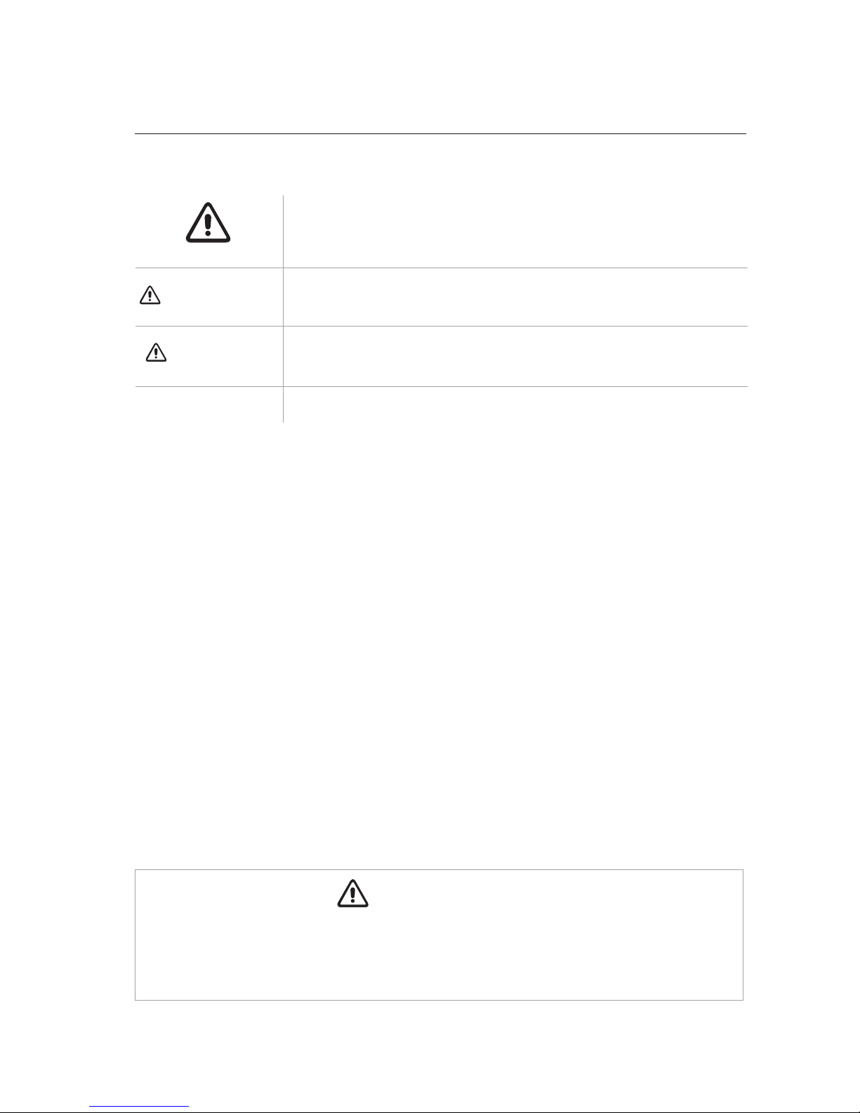
SAFETY PRECAUTIONS
Please read the following before installation.
This is the safety alert symbol. It is used to alert you to potential
personal injury hazards. Obey all safety messages that follow this
symbol to avoid possible injury or death.
This mark indicates procedures which, if improperly performed,
might lead to the death or serious injury of the user.
This mark indicates procedures which, if improperly performed, might
possibly result in personal harm to the user, or damage to property.
Notice is used to address practices not related to personal injury.
General Safety Precautions
1. Instructions for installation and use of this product are provided by the manufacturer.
For proper operation, the system must be installed in accordance with this
installation manual.
2. Installation must be performed in accordance with local laws, regulations and
National Electrical Codes (NEC).
3. If refrigerant leaks while work is being carried out, ventilate the area. Do not allow
refrigerant to come in contact with a flame as it produces toxic gas.
4. Disconnect all electrical power to the indoor and outdoor units until the system is
ready for start-up and checkout.
5. When installing or repairing the system, use only R410A refrigerant. Do not
mix refrigerant with other gases. If air or other gas enter the refrigeration system,
the pressure inside the system may rise to an abnormally high value and cause
damage or injury.
This appliance is not intended for use by persons (including children) with reduced physical,
sensory or mental capabilities, or lack of experience and knowledge, unless they have been given
supervision or instruction concerning use of the appliance by a person responsible for their safety.
WARNING
CAUTION
NOTICE
WARNING
2
Outdoor Unit
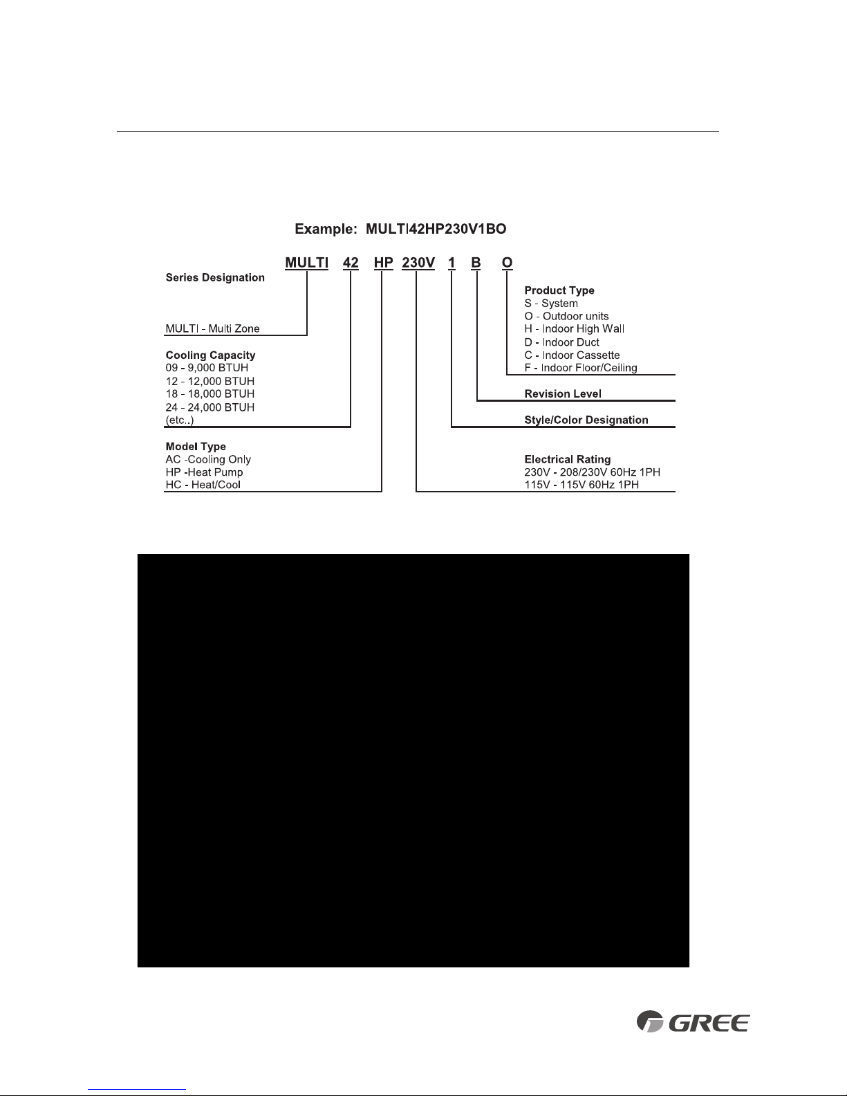
NOMENCLATURE
3

SYSTEM REQUIREMENTS
REFRIGERANT CHARGE
ELECTRICAL REQUIREMENTS
Notes: 1) System must be on a single dedicated circuit.
2) Main power is supplied to the outdoor unit.
3) Use table above to size over current protection.
4) Follow all local building codes and NEC (National Electrical Code) regulations.
Interconnecting Cable: Recommended cable - 14/4 AWG stranded bare copper conductors THHN 600V unshielded wire
Note: Use shield cable if installation is in close proximity of RF and EMI transmitting devices.
Unit Size (BtuH)
Liquid Line
in(mm)
Suction/Gas Line
in(mm)
18,000
Port A 1/4 (6) 3/8 (9.5)
Port B 1/4 (6) 3/8 (9.5)
Port A 1/4 (6) 3/8 (9.5)
24,000 Port B 1/4 (6) 3/8 (9.5)
Port C 1/4 (6) 3/8 (9.5)
Port A 1/4 (6) 3/8 (9.5)
30,000
Port B 1/4 (6) 3/8 (9.5)
Port C 1/4 (6) 3/8 (9.5)
Port D 1/4 (6) 3/8 (9.5)
Port A 1/4 (6) 3/8 (9.5)
36,000
Port B 1/4 (6) 3/8 (9.5)
Port C 1/4 (6) 3/8 (9.5)
Port D 1/4 (6) 3/8 (9.5)
Port E 1/4 (6) 3/8 (9.5)
Port A 1/4 (6) 3/8 (9.5)
Port B 1/4 (6) 3/8 (9.5)
42,000 Port C 1/4 (6) 3/8 (9.5)
Port D 1/4 (6) 3/8 (9.5)
Port E 1/4 (6) 3/8 (9.5)
Unit Size Max Total Pipe
Min
Equivalent Max Equivalent Max Elev btwn Max Elev btwn
(BtuH) Length ft(m) Pipe Length ft(m) Pipe Length ft(m) IND Units ft(m) IND& OTDUnitsft(m)
18,000 65 (20) 10 (3) 33 (10) 33 (10) 33 (10)
24,000 197 (60) 10 (3) 65 (20) 33 (10) 33 (10)
30,000 230 (70) 10 (3) 82 (25) 25 (7.5) 49 (15)
36,000 246 (75) 10 (3) 82 (25) 25 (7.5) 49 (15)
42,000 246 (75) 10 (3) 82 (25) 25 (7.5) 49 (15)
Unit Size
Voltage
Min Circuit Max Overcurrent Main Power
(BtuH) Amps (MCA) Protection (MOP) Wire Size (AWG)**
18,000 208/230v - 1ph 60hz 15 25 12
24,000 208/230v - 1ph 60hz 21 35 8
30,000 208/230v - 1ph 60hz 19 30 10
36,000 208/230v - 1ph 60hz 21 35 8
42,000 208/230v - 1ph 60hz 24 40 8
**Main power wire from electrical panel to outdoor unit. AWG based on 240VAC Single Phase, 100 ft. distance 1-way, max. 5% allowable voltage drop.
REFRIGERANT PIPE LENGTHS
Unit Size Refrigerant Factory System Max Pipe Length w/out Additional
(BtuH) Type Charge oz(kg) adding Refrig ft(m) Charge oz/ft (g/m)
18,000 R-410A 56.5 (1.6) 33 (10) 0.2 (20)
24,000 R-410A 77.6 (2.2) 98 (30) 0.2 (20)
30,000 R-410A 98.7 (2.8) 131 (40) 0.2 (20)
36,000 R-410A 128.8 (3.65) 131 (40) 0.2 (20)
42,000 R-410A 128.8 (3.65) 131 (40) 0.2 (20)
4
• Standard Wrench
• Adjustable/Crescent Wrench
• Torque Wrench
• Hex Keys or Allen Wrenches
• Drill & Drill Bits
• Hole Saw
• Pipe Cutter
• Screw drivers (Phillips & Flat blade)
• Manifold and Gauges
• Level
• R410A Flaring Tool
• Clamp on Amp Meter
• Vacuum Pump
• Safety Glasses
• Work Gloves
• Refrigerant Scale
• Micron Gauge
SUGGESTED TOOLS
5

INSTALLATION SITE INSTRUCTIONS
Indoor Unit
Select a site that allows for the following:
1. Ensure the installation complies with the installation minimum dimensions (defined below)
and meets the minimum and maximum connecting piping length and maximum change in
elevation as defined in the System Requirements section.
2.
Air inlet and outlet will be clear of obstructions, ensuring proper airflow throughout the room.
3. Condensate can be easily and safely drained.
4. All connections can be easily made to outdoor unit.
5. Indoor unit is out of reach of children.
6.
A mounting structure (i.e. wall, ceiling, floor,...) strong enough to withstand four times the full
weight and vibration of the unit.
7. Filter can be easily accessed for cleaning.
8. Leave enough free space to allow access for routine maintenance.
9. Install at least 10 ft. (3 m) away from the antenna of TV set or radio. Operation of the air
conditioner may interfere with radio or TV reception in areas where reception is weak.
An amplifier may be required for the affected device.
10. Do not install in a laundry room or by a swimming pool due to the corrosive environment.
Minimum Indoor Clearances - High Wall Units
NOTE:
For minimum clearances of other indoor unit types, refer to
the Installation Instructions enclosed with those indoor units.
6 in
(0.15m)
6 in
(0.15m)
6 ft (1.8m)
6 in (0.15m)
Ceiling
Floor
6
Air inlet
Air outlet
20 in
(0.5 m)
20 in
(0.5 m)
39 in
(1.0m)
20 in
(0.5 m)
78 in
(2.0 m)
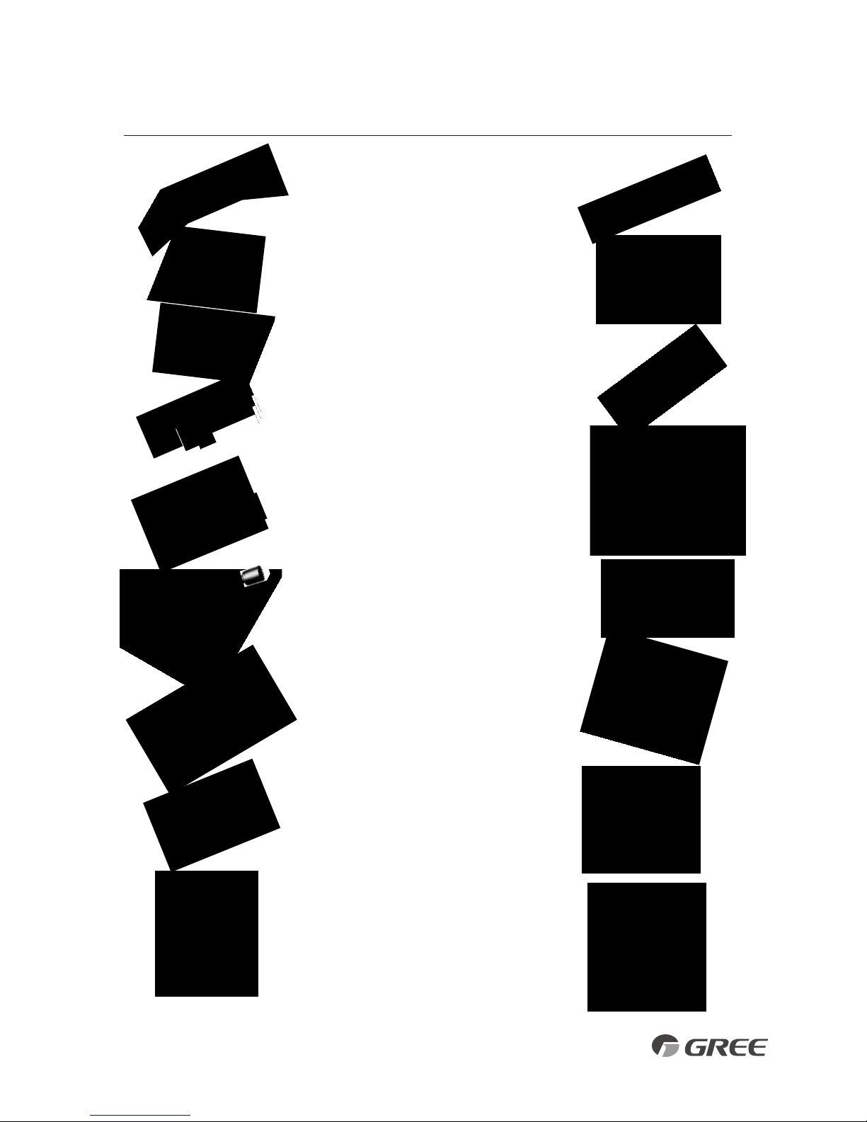
1. Install the outdoor unit at a location that is capable of withstanding twice the weight of the unit.
2. Install the outdoor unit where it is convenient to connect refrigerant lines to the indoor units.
3. Install the outdoor unit where the condensate water can be drained unobstructed during the
heating mode to a safe location.
4. Do not locate the unit where the noise may be objectionable to neighbors.
5. Provide the space shown below, so that the air flow is not blocked and future service and
maintenance can be performed.
Outdoor Unit
INSTALLATION SITE INSTRUCTIONS
Select a site that allows the following:
Air inlet
Air outlet
Minimum Outdoor Clearances
7
12 in
(0.3 m)
20 in
(0.5 m)
20 in
(.05 m)
12 in
(0.3 m)
78 in
(2.0 m)
18K and 24K Unit
30K, 36K and 42K Unit

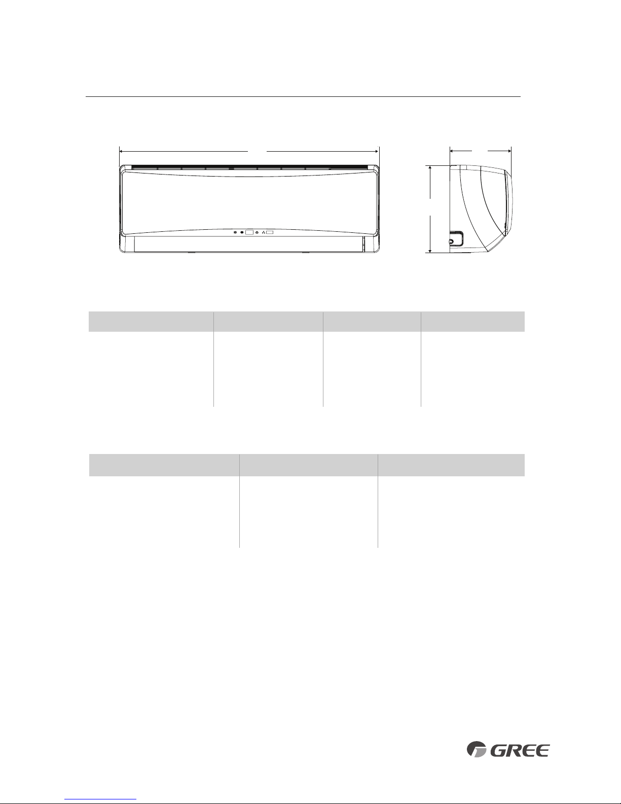
PIPE SIZE – in(mm)
Unit Size (BtuH) Liquid Line Suction/Gas Line
9,000 1/4 (6) 1/2 (12)
12,000 1/4 (6) 1/2 (12)
18,000 1/4 (6) 5/8 (16)
CROWN INDOOR UNIT INSTALLATION
Model ABC
CROWN09HP230V1A
37.8 (960) 12.6 (320) 8.1 (205)
CROWN12HP230V1A
37.8 (960) 12.6 (320) 8.1 (205)
CROWN18HP230V1A
37.8 (960) 12.6 (320) 8.1 (205)
31/2 27 7 3/8
3 1/8
2
INDOOR UNIT DIMENSIONS – in(mm)
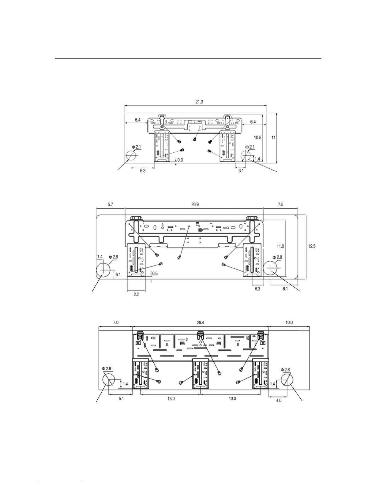
Crown Unit Mounting Bracket Diagram (inches)
9K, 12K and
18K Unit
Crown
8
A
C
B
3.5 27.0 7.1
3.1
2.0
Left
Right
(Rear piping hole)
(Rear piping hole)
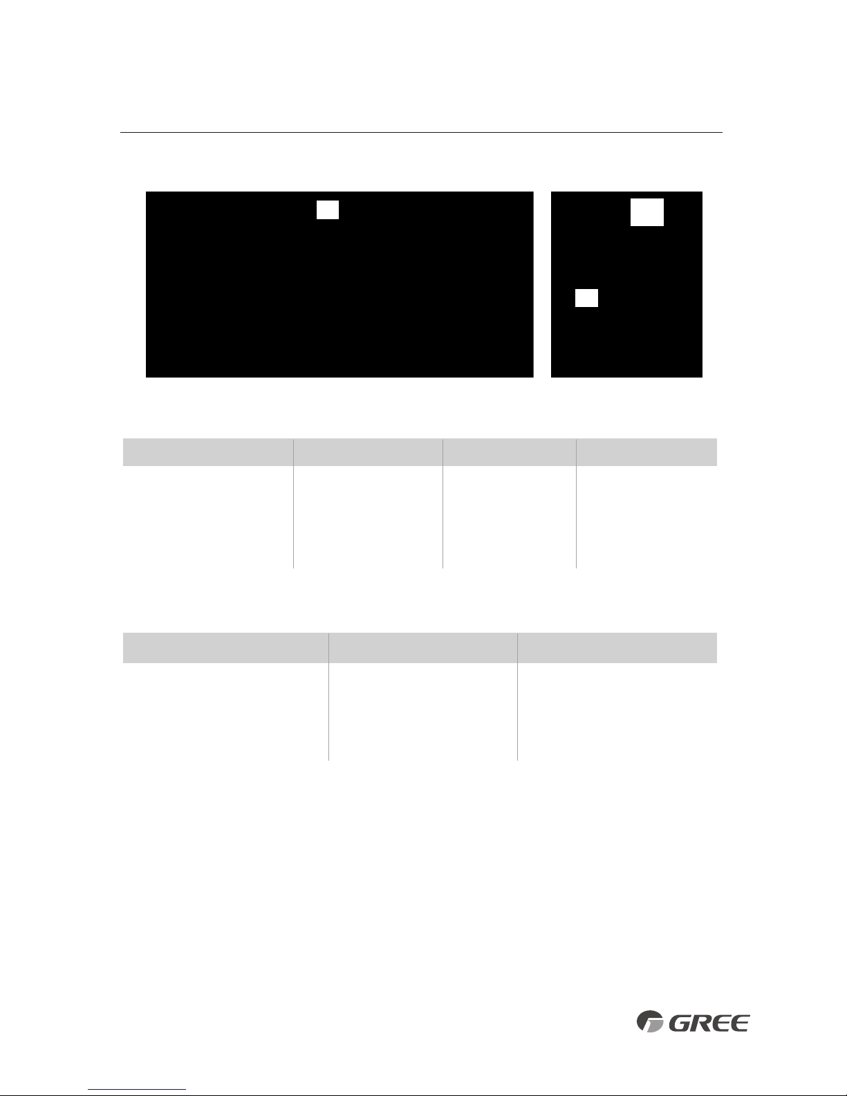
TERRA INDOOR UNIT INSTALLATION
Model ABC
TERRA09HP230V1AH
34.1 (866) 11.5 (292) 8.2 (208)
TERRA12HP230V1AH
34.1 (866) 11.5 (292) 8.2 (208)
TERRA18HP230V1BH
40.1 (1018) 12.6 (319) 9.1 (231)
TERRA24HP230V1BH
46.4 (1178) 12.8 (325) 10.4 (264)
PIPE SIZE – in(mm)
Unit Size (BtuH) Liquid Line Suction/Gas Line
9,000 1/4 (6) 1/2 (12)
12,000 1/4 (6) 1/2 (12)
18,000 1/4 (6) 5/8 (16)
24,000 1/4 (6) 5/8 (16)
INDOOR UNIT DIMENSIONS – in(mm)
9
A
C
B
Terra
TERRA INDOOR UNIT INSTALLATION
Terra Unit Mounting Bracket Diagrams (inches)
9K and 12K Unit
18K Unit
24K Unit
Left Right
(Rear piping hole) (Rear piping hole)
Left
Right
(Rear piping hole)
Left
(Rear piping hole)
(Rear piping hole)
Right
(Rear piping hole)
10
VIREO INDOOR UNIT INSTALLATION
B
C
A
11
Model ABC
VIR09HP230V1A 33.4
(848)
11.4 (290)
8.2
(208)
VIR12HP230V1A 33.4
(848)
11.4 (290)
8.2
(208)
VIR18HP230V1A 38.2 (970) 11.8 (300)
8.8
(224)
VIR24HP230V1A 42.4 (1077) 12.8 (325)
9.7
(246)
PIPE SIZE – in(mm)
Unit Size (BtuH) Liquid Line Suction/Gas Line
9,000 1/4 (6) 3/8 (9)
12,000 1/4 (6) 1/2 (12)
18,000 1/4 (6) 1/2 (12)
24,000 1/4 (6) 5/8 (16)
INDOOR UNIT DIMENSIONS – in(mm)
Vireo
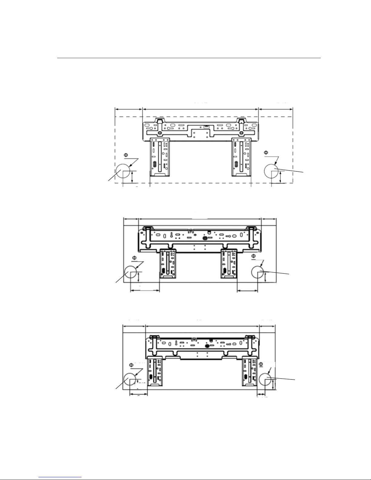
Vireo Unit Mounting Bracket Diagrams (inches)
VIREO INDOOR UNIT INSTALLATION
9K and 12K Unit
18K Unit
24K Unit
4
.6
2
1.4
7
.3
4 27 7.3
8.1 27
6.0
3.1
7.4
1.4
1.4
1.5
7.5 5.5
1.5
1.6
1.6
2.3
2.3
2.3
2.3
2.8
2.8
12
Left
Right
(Rear piping hole)
(Rear piping hole)
Right
(Rear piping hole)
Right
(Rear piping hole)
Left
(Rear piping hole)
Left
(Rear piping hole)
 Loading...