

Gree A Series, LSQWRF35VM/NaA-M, LSQWRF60VM/NaA-M, LSQWRF65VM/NaA-M, LSQWRF70VM/NaA-M Installation, Start-up And Maintenance Manual
Page 1
A Series Inverter Modular Air-cooled Chiller (Heat Pump)
LSQWRF35VM/NaA-M、LSQWRF60VM/NaA-M
LSQWRF65VM/NaA-M、LSQWRF70VM/NaA-M
Page 2

To Users
Thank you for selecting Gree’s product. Please read this instruction manual carefully before
installing and using the product, so as to master and correctly use the product. In order to
guide you to correctly install and use our product and achieve expected operating effect, we
hereby instruct as below:
(1)This equipment should be installed, operated or maintained by the qualified
servicemen who have had specific training. During operation, all safety issues
covered in the labels, User’s Manual and other literature should be followed strictly.
This equipment is not intended for use by persons (including children) with reduced
physical, sensory or mental capabilities, or lack of experience and knowledge, unless
they have been given supervision or instruction concerning use of the appliance by a
person responsibility for their safety. Children should be supervised to ensure that
they do not play with the appliance.
(2)This product has gone through strict inspection and operational test before leaving the
factory. In order to avoid damage due to improper disassembly and inspection, which
may impact the normal operation of unit, please do not disassemble the unit by
yourself. You can contact with the special maintenance center of our company if
necessary.
(3)For personal injury or property loss and damage caused by improper operation such as
improper installation and debugging, unnecessary maintenance, violation of related
national laws and rules and industrial standard, and violation of this instruction
manual, etc., we will bear no liability.
(4)When the product is faulted and cannot be operated, please contact with our
maintenance center as soon as possible by providing the following information.
1) Contents of nameplate of product (model, cooling/heating capacity, product No.,
ex-factory date).
2) Malfunction status (specify the situations before and after the error occurs).
(5)All the illustrations and information in the instruction manual are only for reference. In
order to make the product better, we will continuously conduct improvement and
innovation. We have the right to make necessary revision to the product from time to
time due to the reason of sales or production, and reserve the right to revise the
contents without further notice.
(6)The final right to interpret for this instruction manual belongs to Gree Electric
Appliances Inc. of Zhuhai.
Page 3

Contents
1 Safety Notices............................................................................................................ 1
2 General Introduction .................................................................................................. 6
2.1 Product Features ................................................................................................. 7
2.2 Principle Diagrams .............................................................................................. 8
3 Operation Range ....................................................................................................... 8
4 Outline Dimensions ................................................................................................... 9
5 Installation Instructions ............................................................................................ 10
5.1 Pre-check........................................................................................................... 10
5.2 Acceptance Check............................................................................................. 10
5.3 Handling and Lifting............................................................................................11
5.4 Installation Foundation and Service Space ....................................................... 12
5.5 Vibration Reduction ........................................................................................... 13
5.6 Installation of the Water System ........................................................................ 14
6 Introduction to the Display Panel............................................................................. 16
7 Electric Wiring.......................................................................................................... 16
7.1 External Wiring of the Electric Control Cabinet ................................................. 16
7.2 Specification of Power Cord and Air Switch ...................................................... 17
7.3 Wiring of the Electric Control Cabinet................................................................ 18
7.4 Filed Wiring ........................................................................................................ 18
7.5 Networking and Wiring between Units .............................................................. 20
7.6 Setup of Toggle Switches on the Motherboard.................................................. 21
7.7 Jumpers ............................................................................................................. 22
8 Commissioning and Maintenance ........................................................................... 23
8.1 Check before Startup......................................................................................... 23
8.2 Requirements on Water Quality and Cleaning .................................................. 23
8.3 Trial Run ............................................................................................................ 25
8.4 Routine Startup/Shutdown ................................................................................ 25
8.5 Maintenance to the Main Parts.......................................................................... 26
8.6 Maintenance during Long-term Downtime ........................................................ 26
8.7 Startup after Long-term Shutdown .................................................................... 26
8.8 Parts Replacement ............................................................................................ 26
8.9 Refrigerant Charging ......................................................................................... 27
8.10 Removal of the Compressor............................................................................ 27
8.11 Freeze Protection............................................................................................. 28
Page 4

8.12 Rountine Maintenance..................................................................................... 28
8.13 Precautions...................................................................................................... 29
9 Troubleshooting and After-sales Service ................................................................ 30
9.1 Troubleshooting Measures ................................................................................ 30
9.2 After-sales Service ............................................................................................ 32
Page 5
A Series Inverter Modular Air-cooled Chiller (Heat Pump)
1 Safety Notices
Warning:If not abide strictly, it may cause severe damage to the unit or the people.
Note:If not abide strictly, it may cause slight or medium damage to the unit or the people.
This sign indicates that the operation must be prohibited. Improper operation may cause
severe damage or death to people.
This sign indicates that the items must be observed. Improper operation may cause
damage to people or property.
◆Safety Notices for On-site Installation
WARNING
(1)Installation should be performed by qualified servicemen who have taken
specialized training and acquired corresponding certificates in accordance with
relative laws, regulations and this manual, otherwise it would lead to damage to the
unit, water leakage, electrocution, or fire hazards etc.
(2)The unit should be installed on the smooth foundation capable of supporting the unit
and fixed with screw bolts. The foundation with inadequate strength would lead to
leakage, turn-over or personal injury or death.
(3)Special lines should be used for electric installation by qualified electricians. Lines
with inadequate capacity would lead to electrocution or fire hazards.
(4)Make sure each connector is properly tightened; otherwise it would lead to
overtemperature or fire hazards etc.
(5)When installation is finished, please check for the drainage lines, pipelines, and
electric lines to prevent water leakage, electrocution or fire hazards.
(6)This equipment should be installed where the drainage system can work well. Never
block the drain hole. Improper drainage system would lead to drainage difficulty and
make the unit suffer from malfunctions.
(7)When there is something unusual (like stinky smell) during installation or
commissioning, please cut off the main power at once and then contact the
aftersales service center. This ongoing unusual condition will damage the air
conditioning unit and lead to electrocution or fire hazards
(8)When refrigerant leaks, take corrective measures as soon as possible to prevent
oxygen depletion by increased refrigerant concentration.
1
Page 6
A Series Inverter Modular Air-cooled Chiller (Heat Pump)
NOTE
(1)Do not install the unit where there is high-intensity magnetic field or it is highly basic
or acid or the voltage is quietly unstable.
(2)Do not install the unit where there would be leaked inflammable gas, as it would lead
to fire hazards.
(3)The outer casing of the unit should be grounded. Do not connect the grounding line
to the gas line, water line, lightning rod or communication line, otherwise it would
lead to electric shocks.
(4)Do not stand on the unit or place other object on it.
(5)Do not insert fingers or other objects into the outlet grill to prevent damage to the unit
or personal injury or death.
(6)Do not start or stop the unit by inserting or drawing out the power plug.
(7)Do not let children play with this unit.
(8)The unit should be equipped with the leakage protector which should be installed in
accordance with electric technical standards. Uninstallation or incorrect installation
would lead to electrocution. Do electric leakage detection after electric installation is
finished.
(9)Volatile liquid like thinner or gasoline would damage appearance of the unit. (Only
clean the outer casing with of the unit with soft dry cloth or wet cloth with neutral
detergent.
DANGER
(1)Do not install the unit where conditions are severe, where it is close to the hot spring,
coast or oil field, as it would lead to corrosion, electrocution or fire hazards.
Besides, do not install the unit where there are corrosive, inflammable substances
or smog, otherwise it would lead to normal operation failure, shortened service life,
fire hazard, or severe injury.
(2)Do not start the compressor by manually closing the AC contactor, otherwise it would
lead to electrocution or fire hazard.
(3)Do not misuse refrigerant, as it would lead to normal operation failure, unsatisfactory
performance, fire hazards or even explosion etc.
2
Page 7
A Series Inverter Modular Air-cooled Chiller (Heat Pump)
CAUTION
(1)Installation should be done in accordance with this manual. Please read it manually
prior to startup or troubleshooting.
(2)Installation should be done by qualified servicemen, as incorrect installation would
lead to water leakage, electrocution or fire hazards etc.
(3)Before installation, check for all power supplies with the nameplate and check for its
safety.
(4)The unit should be grounded and there should be specialized grounding line for the
power socket to avoid of electrocution. Do not connect the groundling line to the gas
tank, water line, lightning rod, or telephone line.
(5)Only specialized accessories and parts are allowed for installation, otherwise it
would lead to water leakage, electrocution or fire hazards etc.
(6)Size of the power lines should be large enough. Only specialized power lines are
allowed for replacing the damaged ones.
(7)When power lines have been connected, install the electric box as well to avoid of
any safety problems.
(8)After all installation has been finished, take an overall check to the unit before
powering it on.
◆Safety Precautions for Usage and Maintenance
WARNING
(1)When there is something unusual (like burnt smell), cut off the power supply at once
and contact the sales agent. The ongoing unusual condition would lead to
malfunctions, electrocution or fire hazards.
(2)When refrigerant leaks, take corrective measures to prevent oxygen depletion by
increasing refrigerant concentration.
(3)Do not use or place inflammable or explosive substances near the unit.
(4)Do not do troubleshooting personally, as incorrect troubleshooting would lead to
electrocution or fire hazards. Instead, please contact GREE after-sales service
center.
(5)When the unit is charged with refrigerant, do not solder or cut any pipeline, fined
heat exchanger, shell-and-tube heat exchanger or other containers.
3
Page 8
A Series Inverter Modular Air-cooled Chiller (Heat Pump)
NOTE
(1)Do not let the unit out of the designed application range; otherwise it would cause
the heat exchanging tube cracking, refrigerant leakage or even explosion.
(2)Do not let the cold/heat source directly act on the stored foods, plants, animals,
precision instruments, and curiosities, otherwise their quality would be degraded.
(3)Only circulating water with satisfactory water qualify are allowed for the unit, as
unsatisfactory water quality would shorten the service life of the unit or even
malfunctions.
(4)When the unit has been put into use for some time, check for security of the
installation foundation. Unstable foundation would lead to deformation or even
safety accident.
(5)Once the unit is started up, stop it at least 6 minutes later, otherwise it would shorten
the service life of the unit. Never deliberately start or stop the unit frequently.
(6)Under subzero climatic conditions, pay attention to freeze protection. When the unit
is out of use in short time, do not cut off the power supply, as freeze protection will
not act normally. When the unit is out of used in quite long time, add anti-freezing
agent to water or drain the water system, otherwise it would make the shell and
tube crack and then leak.
DANGER
(1)Do not use the fuse out of the normal range or replace it with the electric wire,
otherwise it would damage the unit or lead to fire hazards.
(2)Do not start or stop the unit directly by the power switch, as it would be likely to
cause electrocution or fire hazards.
(3)Do not change settings of safety devices; otherwise it would lead to fire hazards and
explosion.
(4)Do not operate the unit with wet hands.
(5)Do not clean the unit without cutting off the power supply, as it would lead to
electrocution or personal injury.
(6)Do not let children pull power lines or climb the unit to prevent of electrocution or
other dangers.
(7)Do not touch high-temperature parts of the compressor and refrigerant lines, as it
would lead to burns.
(8)Do not touch sharp edges and fins of the heat exchanger; otherwise it would lead to
personal injury.。
(9)Do not touch any moving part; otherwise it would lead to accidental injury.
(10)Do not stand on the unit or replace objects on it.
(11)Do not bend pipeline and retrofit the unit, otherwise it would lead to refrigerant
leakage, explosion, fire hazards or personal injury.
4
Page 9
A Series Inverter Modular Air-cooled Chiller (Heat Pump)
CAUTION
(1)Do operate the unit in accordance with this manual and read it carefully before
startup or troubleshooting.
(2)Do turn on or off the unit with the controller.
5
Page 10
A Series Inverter Modular Air-cooled Chiller (Heat Pump)
◆Safety Precaution for Handling of the Unit
Safety Precaution for Handling of the Unit
WARNING
(1)Please contact the contractor for handling and installation. Improper installation
would lead to electrocution or fire hazard.
(2)During installation or handling, do not let foreign matters mixed with refrigerant and
do not air trapped inside the pipe, as it would lead to increased system pressure or
explosion of the compressor.
(3)Only specialized power lines are allowed. Wiring terminals should suffer no any
external force and are fixed properly; otherwise it would lead to fire hazards.
Besides, make sure insulation of power lines always in good condition.
(4)Connection between two ends of the power lines is not allowed. When its length is
not enough, please contact the after-sales service center for customizing another
one long enough.
CAUTION
(1)Treatment of water, cleaning solution, refrigerant or other waste liquid or gas should
comply with local laws and regulations; otherwise it would lead to adverse effect to
health and environment.
(2)Do not misuse refrigerant, as it is one of the causes of fire hazard and explosion.
Precautions for Refrigerant Charging
NOTE
When charging is interrupted or finished, reinspect the unit but do not let the compressor
run into operation.
WARNING
Do not use mixture of refrigerant vapor and air or oxygen for pressurizing for fear of
explosion.
2 General Introduction
See the nameplate for the main technical data.
The all-inverter modular air-cooled chillers are capable of performing cooling all year around
with high energy efficient. It requires no cooling towers and is quite applicable to water-
deficient areas, and can be widely used at newly built or retrofitted industrial and civil buildings
in various sizes, such as, hotels, apartments, restaurants, office buildings, shopping malls,
theaters, gyms, workshops, hospitals, places where there is requirement on cooling under
ultra-low temperature, like cold storages, places where require cooling for dairy products,
foods and industrial products, and especially places where there are high requirements on
6
Page 11

A Series Inverter Modular Air-cooled Chiller (Heat Pump)
noise level and surrounding environment and boils and cooling towers are not allowed or hard
to be installed.
2.1 Product Features
The all-inverter modular air-cooled chillers work outstandingly by virtue of their major
features stated below..
■ Excellent compatibility:
The all-inverter modular air-cooled chillers can be constructed of multiple single units with
the same or different structure or capability (30kW, 60kW, 65kW and 70kW). For the 35kW
unit, it has only one cooling system; for the 60kW, 65kW and 70kW units, they are of two
independent systems. Up to 16 single units can be modularized, with cooling capacity ranging
from 35kW to 1104kW.
■ Comfort and energy saving:
The variable-frequency technology can quickly respond to load change and lead to
decreased water temperature fluctuation and better comfort.
■ Ultra-quiet:
The high-efficiency and low-noise fan blades and motor as well as the optimized air passage
can greatly lower operation noise of the unit. Besides, the quite mode can provide the user a
ultra-quite environment.
■ Powerful self-protection:
It is equipped with the top-end microcomputer control system which is capable of providing
well-rounded protection and self-diagnosis.
■ High reliability:
It is constructed of well-designed refrigeration parts and well-designed system, structure
and electric control, adequately guaranteeing reliable operation
■ Remote ON/OFF:
The unit can be started or stopped by the ON/OFF key operation.
■ Equilibrium running:
It indicates each compressor will run alternately so as to extend their service life.
■ Shiftwork of water pumps:
Two water pumps can work alternately with equilibrium runtime so as to extend their service
life and lower the maintenance difficulty.
7
Page 12
A Series Inverter Modular Air-cooled Chiller (Heat Pump)
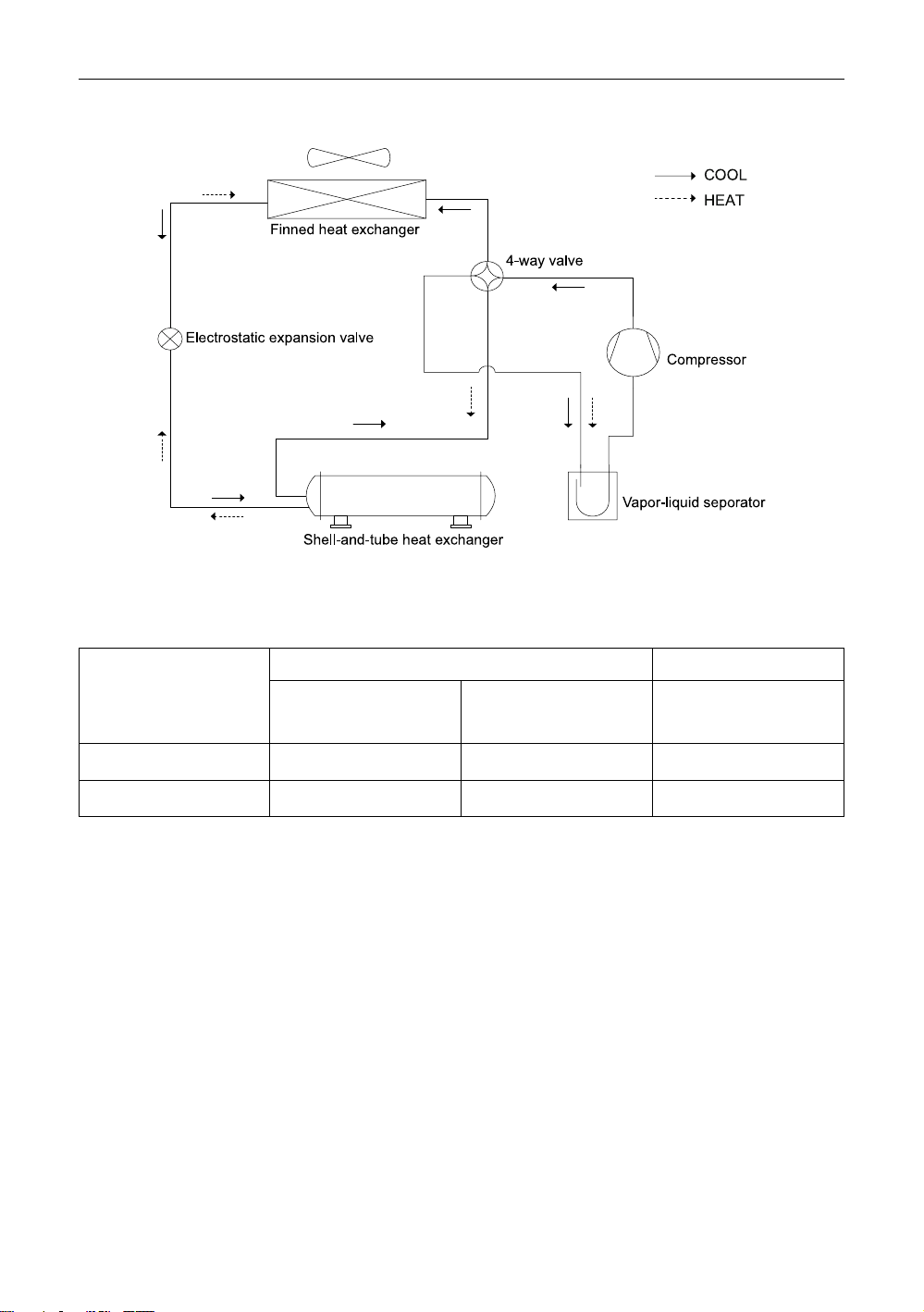
2.2 Principle Diagrams
3 Operation Range
Please run the unit under the specified operation range as shown in the table below:
■ R410A Series
Item
Cooling
Heating
Water Side Air Side
Leaving Water
Temperature(℃)
5~20 2.5~6 –15~52
35~50 2.5~6 -20~40
Water Temperature
Difference(℃)
Ambient DB
Temperature(℃)
8
Page 13
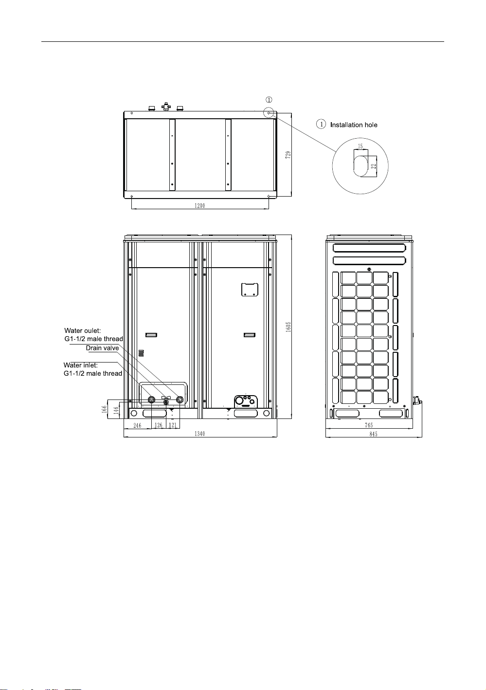
4 Outline Dimensions
(1)LSQWRF35VM/NaA-M(unit:mm)
A Series Inverter Modular Air-cooled Chiller (Heat Pump)
9
Page 14
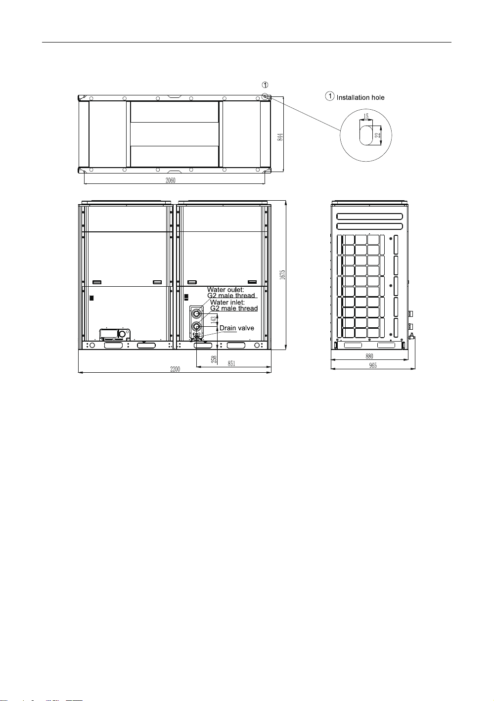
A Series Inverter Modular Air-cooled Chiller (Heat Pump)
(2)LSQWRF60VM/NaA-M, LSQWRF65VM/NaA-M,LSQWRF70VM/NaA-M (unit:mm)
5 Installation Instructions
5.1 Pre-check
Installation should be performed by the skilled technician to guarantee the normal operation
and prevent malfunctions and please read this manual carefully prior to installation.
The chiller is manufactured, inspected and tested strictly in accordance with the quality
control program and it will work properly within the expected service life as long as its
installation, operation and service.
5.2 Acceptance Check
The user is responsible for organizing personnel to perform the acceptance check at the
regulated plate of delivery. Checks listed below should be taken as a minimum.
(1)If all required documents and accessories are provided as per the packing list.
(2)Check the equipment model.
(3)If the equipment is damaged and all parts are provided.
(4)If refrigerant leaks.
(5)Do not remove the protective cover on the flagon of the shell-and-tube heat exchanger
before connecting the water tube and check if the water pipe is clean.
(6)Check if the installation and operation are within the allowable conditions.
10
Page 15
A Series Inverter Modular Air-cooled Chiller (Heat Pump)
When there is damager or any other question, contact the local sales representative for
applicable solutions.
NOTE
After the acceptance check, take necessary protection to the unpacked equipment. Note
that it is not recommended to unpack the equipment too early to avoid any unexpected
damage.
5.3 Handling and Lifting
Each unit will undergo a series of strict factory inspections and tests to guarantee the
expected performance and quality. However, special attention should be paid during handling
and shipping to prevent the control system and the piping system from being damaged.
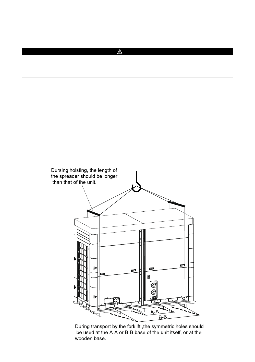
The unit should be moved by the forklift or hoisting machine. During lifting, the canvas lifting
or steel ropes in use should be of enough strength and go through the based and then bundled
tightly. The unit should be lifted stably from four corners. Meanwhile, be sure there should be
protective pads to prevent lifting ropes contacting with the unit. The inclination angle during
lifting should be less than 15 degree. The unit should be moved softly and severe collision and
forced drag are not allowed. Please do lifting as shown in the figure below for units with similar
structure.
11
Page 16
A Series Inverter Modular Air-cooled Chiller (Heat Pump)
5.4 Installation Foundation and Service Space
(1)Installation foundation shall be designed by the qualified designer in accordance with
the actual condition.
(2)A rubber pad shall be placed under the base of each single unit and then secured on
the ground or the roof. Alternatively, each single unit can be placed side by side on the
parallel channel steel with enough strength which then shall be secured with anchor
bolts. Distance between each single unit shall be keep 0.5m as a minimal.
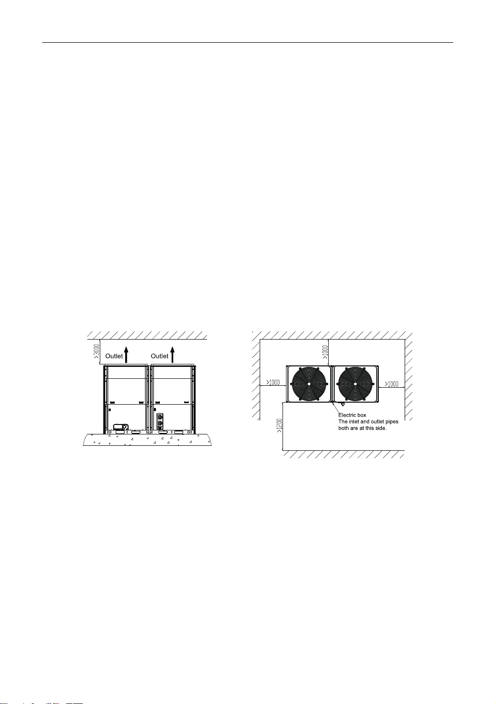
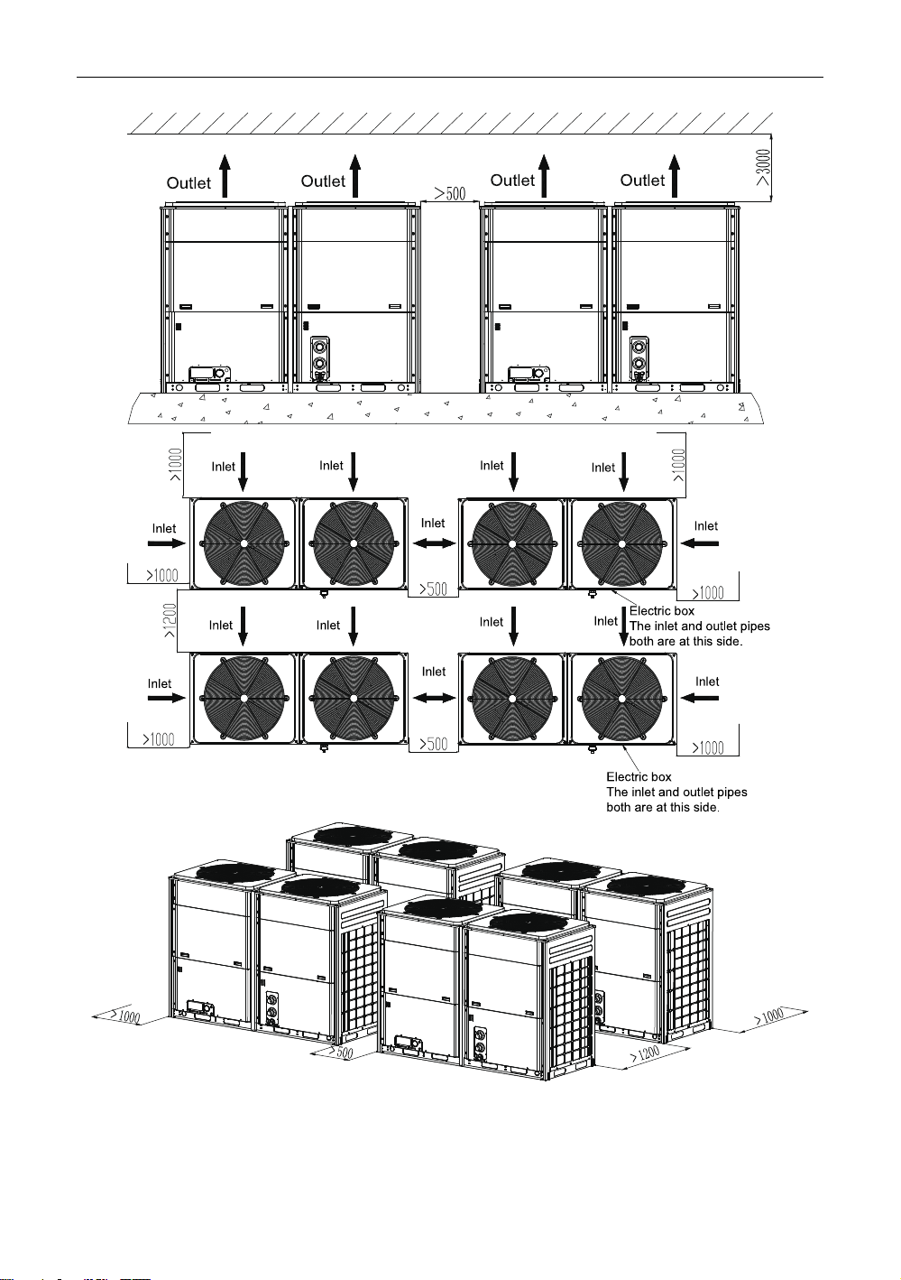
(3)Enough space shall be left for service and ventilation. Be sure there is at least 2m
between the equipment and any barrier and it is better to set up a sun cover 3m ahead
of the equipment.
(4)The unit shall be installed where it will not be affected by fire, corrosive, inflammable or
waste gas, and proper measures shall be taken to minimize the vibration and noise.
(5)The unit shall be installed where the defrosting water can be drained out favorably
(6)Do not install the unit where there is heavy snow. If inevitable, build a foundation at
least 300mm higher than the ground.
■ Installation Space for the Single Unit
(Unit:mm)
■ Installation Space for Modularized Units
12
(Unit:mm)
Page 17
A Series Inverter Modular Air-cooled Chiller (Heat Pump)
Note: diagrams above are just for reference and not in real proportion.
5.5 Vibration Reduction
The unit shall be securely attached to the foundation through the mounting hole by following
the steps below.
13
Page 18

A Series Inverter Modular Air-cooled Chiller (Heat Pump)
(1)Be sure the planeness of the concrete foundation is within ±3mm and the foundation
shall be covered by a rubber pad.
(2)Lift the unit until to the height where it is available to install the spring shock absorber.
(3)Remove screws fixing the spring shock absorber.
(4)Place the unit on the spring shock absorber and align the bolt holes of the spring shock
absorber with the mounting holes on the base of the unit.
(5)Tighten screws removed in step 2.
(6)Adjust the height of the spring shock absorber and make sure the deflection is equal all
round the spring shock absorber.
(7)Tighten the locking screws.
5.6 Installation of the Water System
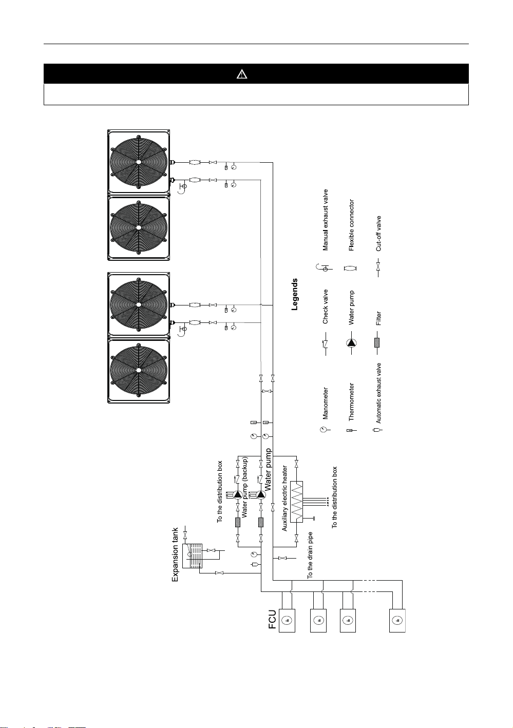
■ Considerations stated below shall be taken carfelly for the water system.
(1)Each water inlet and outlet should be labeled properly to avoid misconnection.
(2)A flexible connector should be used at the chilled water outlet to reduce vibration
transmission.
(3)A manometer, a thermometer and a gate valve shall be installed at the chilled water
inlet /outlet. Moreover, a drain valve shall be installed at the outlet and an air release
valve shall be installed at the inlet. At the highest point of the water system, another
release valve shall be installed, while at the lowest point of the water system, another
drain valve shall be installed to facilitate drainage.
(4)The water inlet/outlet pipe should be tightly insulated to reduce heat loss and dewing.
When pipes are exposed under 0℃, a electric heater shall be installed.
(5)There surely be some foreign matters in the water system which would generate scale
on the surface of the heat exchanger, so a filter shall be installed upstream of the
water pump.
(6)The unit shall be bypassed during flushing to prevent drain out from entering the
system.
(7)Under ultra-low temperature in winter, showdown at night will cause the evaporator
and pipeline frozen up, so it is highly recommended to add alcohol and propanol
mixture in chilled water. Do not cut off the power supply when the unit is turned off,
otherwise the freeze protection does not work. Alternatively, cut off the power supply
and drain the water system thoroughly.
(8)When the unit runs under the low load requirement, in order to avoid low load
protection which would affect the service life of the unit, make sure the water capacity
is more than 1/6 of total rated flow rate per hour of each module (for instance, for
some project with four modularized LSQWRF60VM/Na-M units, if the rated water flow
of each unit is 10.3m
larger than 10.3*4*1/6=6.87m
is required; otherwise the service life of the unit would be affected.
3
/h, then the required capacity of the whole project should be
3
/h). When the water course is quite short, a water tank
14
Page 19
A Series Inverter Modular Air-cooled Chiller (Heat Pump)
NOTE
Never use salt mixture to prevent the unit from being corroded.
■ How to install the water system
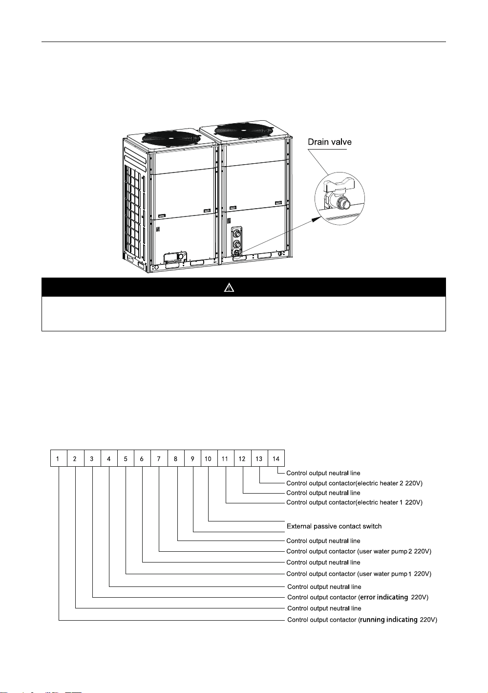
■ How to drain the water system:
(1)Loosen screws around the panel and then take down it.
15
Page 20
A Series Inverter Modular Air-cooled Chiller (Heat Pump)
(2)Remove anticlockwise the blind plug located at the bottom of the heat exchanger to let
the chilled water flow out, after that, tighten the blind plug and reinstall the panel. (-
Note: place the drainage equipment beneath the drain pipe to prevent pollution
caused by the drain water.
NOTE
Keep the purge valve of the water system open in order to drain the evaporator and
condenser completely.
6 Introduction to the Display Panel
See the Operation Instructions for the Display Panel of the inverter modular type chillers for
more details.
7 Electric Wiring
7.1 External Wiring of the Electric Control Cabinet
■ LSQWRF35VM/NaA-M,LSQWRF60VM/NaA-M,LSQWRF65VM/NaA-M and
LSQWRF70VM/NaA-M
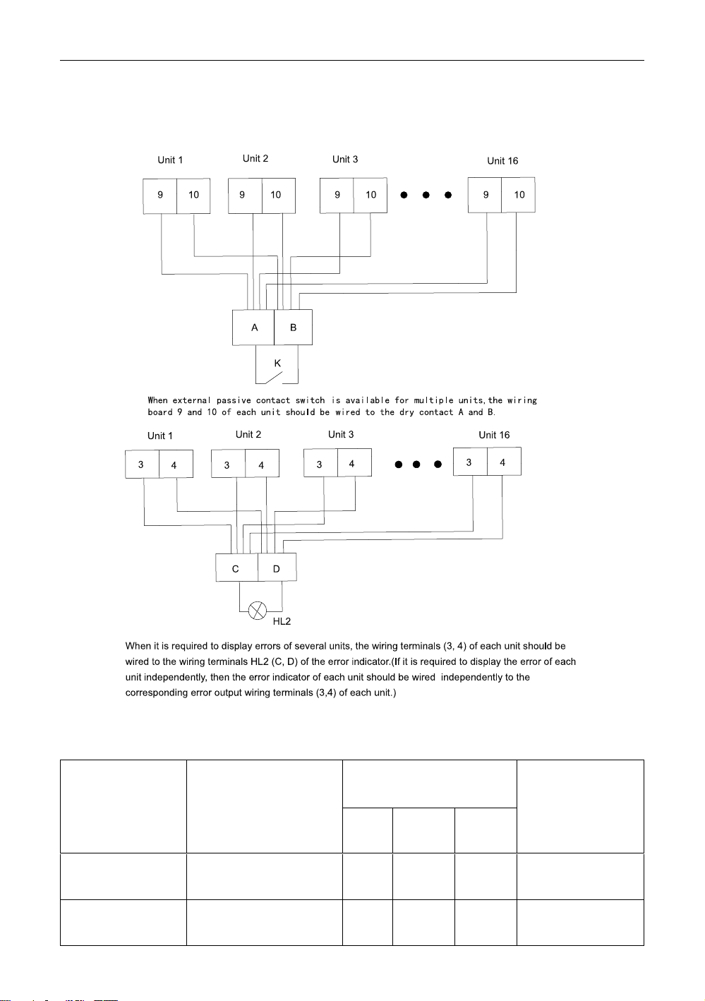
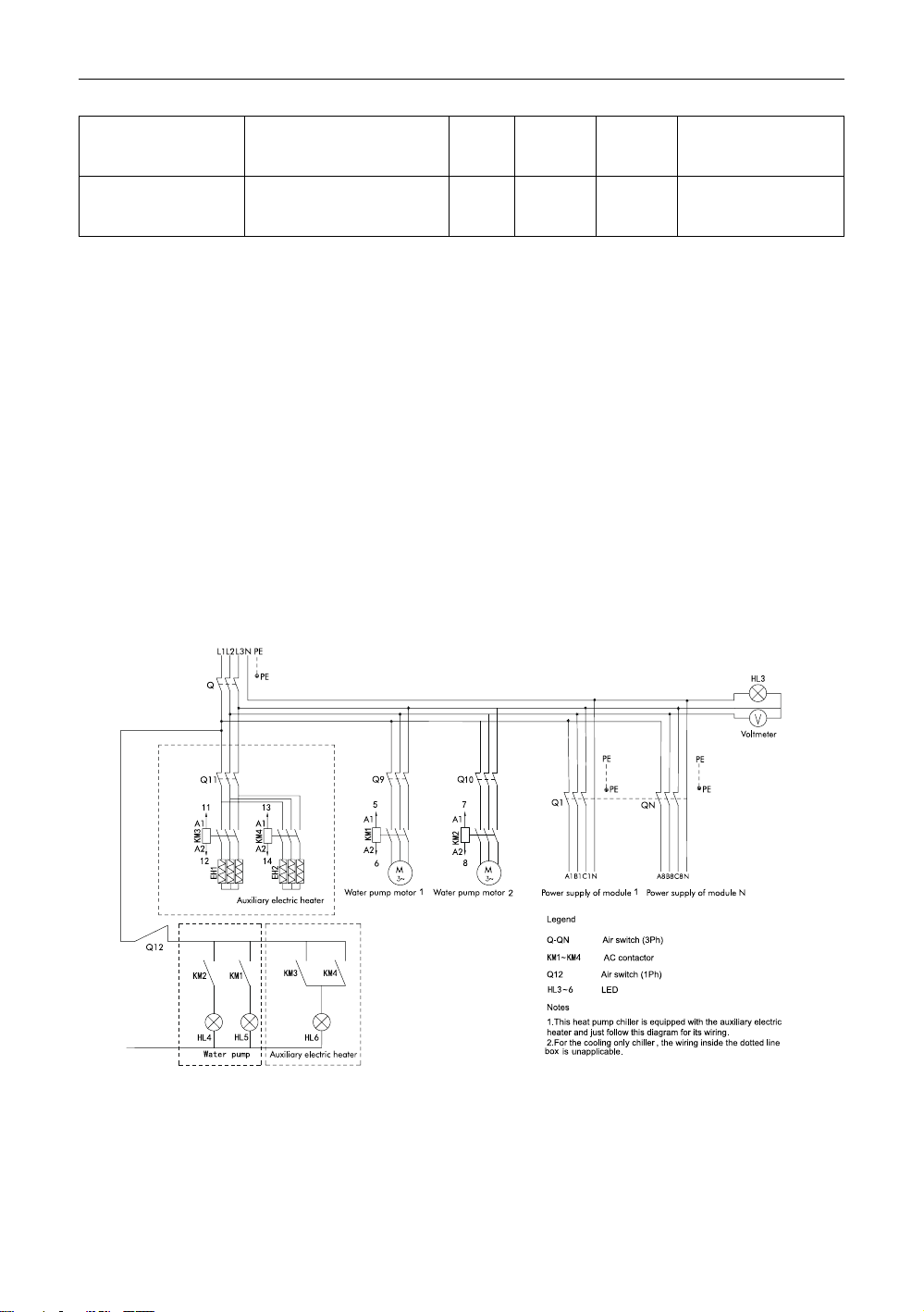
Note: the output control lines of the AC contactors for the running indicator, water pump 1,
water pump 2, auxiliary electric heater 1, auxiliary electric heater 2 can be wired to the
16
Page 21
A Series Inverter Modular Air-cooled Chiller (Heat Pump)
corresponding wiring board of any one unit, while those for the error indicator and extemal
passive contact switch should be wired to the corresponding wiring board of all units as shown
in the figure below.
7.2 Specification of Power Cord and Air Switch
See the table below for selectin of the power lines and the air switches.
Min. sectional area of the
Model
LSQWRF35VM/
NaA-M
LSQWRF60VM/
NaA-M
Power Supply
380V~415VAC 3Ph
50Hz
380V~415VAC 3Ph
50Hz
power cable(mm
Live
Line
17
Neutral
Line
6 6 6 32
16 16 16 63
Earth
2
)
Line
Capability of the
Air Switch Live
(A)
Page 22
A Series Inverter Modular Air-cooled Chiller (Heat Pump)
LSQWRF65VM/
NaA-M
LSQWRF70VM/
NaA-M
Notes:
(1)The specifications of the breaker and power cable listed in the table above are
determined based on the maximum power (maximum amps) of the unit.
(2)The specifications of the power cable listed in the table above are applied to the
conduit-guarded multi-wire copper cable (like, JYV copper cable, consisting of PV
insulated wires and a PVC cable jacket) used at 45℃ and resistible to 90℃(GB/T
16895.15-2002). If the working condition changes, they should be modified according
to the related national standard.
(3)The specifications of the breaker listed in the table above are applied to the breaker
with the working temperature at 40℃. If the working condition changes, they should
be modified according to the related national standard.
380V~415VAC 3Ph
50Hz
380V~415VAC 3Ph
50Hz
16 16 16 63
16 16 16 63
7.3 Wiring of the Electric Control Cabinet
■ LSQWRF35VM/NaA-M,LSQWRF60VM/NaA-M, LSQWRF65VM/NaA-M,
LSQWRF70VM/NaA-M
7.4 Filed Wiring
■ Safety Codes
(1)All wiring shall comply with applicable codes and engineering requirements.
(2)All field wiring shall be performed by the qualified electrician.
(3)Never perform wiring before the power supply is cut off.
18
Page 23
A Series Inverter Modular Air-cooled Chiller (Heat Pump)
(4)Any damage caused by the improper external wiring shall be at the installer’s expense.
WARNING
Only copper conductor is allowed.
■ How to wire the power lines to the electric box
(1)The power cord must be routed inside the conduit.
(2)The power cord must enter the electric box through a rubber or plastic ring to avoid any
damaged caused by the sharp edge of the metal sheet.
(3)The power cord close to the electric box must be attached securely to prevent the
terminal block of the electric box affected by the outside force. The Power cord shall
be installed with a suitable cord anchorage against cord loosing.
(4)The unit shall be grounded reliably and never connect the ground wire with the gas fuel
pipe, water pipe, lightening rod or telephone line.
(5)After wiring, O-rings should be tightened to prevent coming of insects.
■ Control Line
(1)The field supplied control line shall be at a minimum 1mm
2
.
(2)The electric box will send the control signal (220 AC, 5A) to control the chilled water
pump and auxiliary electric heater, however, never do not drive them directly through
the control signal but through their AC contactors.
(3)Switching signals (220VAC, 2A) for the running and error indicators are available for
the electric box.
(4)The remote switch control signal is available for the electric box and please pay
attention to the input passive dry contact.
(5)A reasonable length of the control line should be left outside the unit and the rest
should be bundled and fed into the electric box.
(6)The connection line of the display panel and main board is reliably grounded through
the main board. Beside, communication lines between units also should be grounded.
19
Page 24
A Series Inverter Modular Air-cooled Chiller (Heat Pump)
7.5 Networking and Wiring between Units
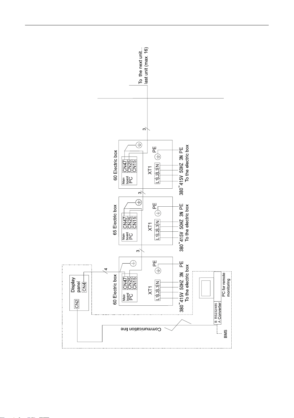
Notes
(1)CN25 and C47 of each unit should be connected through the three-core grounded
communication line with the shielding layer. The ground wire of the communication
lien should be grounded reliably as shown in the figure above.
20
Page 25

A Series Inverter Modular Air-cooled Chiller (Heat Pump)
(2)The CN4 of the display panel should be connected to the unused CN47 at the main
board of the unit though the four-core grounded communication with the shielding
layer. Pay attention that the grounding wire of the communication line is close to the
main board and should be connected to it.
(3)The power lines should be connected to L1, L2, L3, and N at XT1 through a piece of
four-core rubber sleeve cable as shown in the figure above.
(4)There are two solutions for remote monitoring.
1) Install the remote monitoring software at the PC.
2) Based on GREE provided Modbus protocol, the user can do second development
to this protocol.
Note: those enclosed by the dotted lines indicate the remote monitoring equipment.
When the quantity of the display panel exceeds 30 or length of the communication line
exceeds 800m, extra photoelectric relay is required. The photoelectric relays,
communication lines (class 5 twist pairs), converters are optional. PC should be
prepared by the user themselves.
(5)“35” indicates the unit LSQWRF35VM/NaA-M. Each unit is taken as a module.
“60” indicates the unit LSQWRF60VM/NaA-M. Each unit is taken as a module.
“65” indicates the unit LSQWRF65VM/NaA-M. Each unit is taken as a module.
“70” indicates the unit LSQWRF70VM/NaA-M. Each unit is taken as a module.
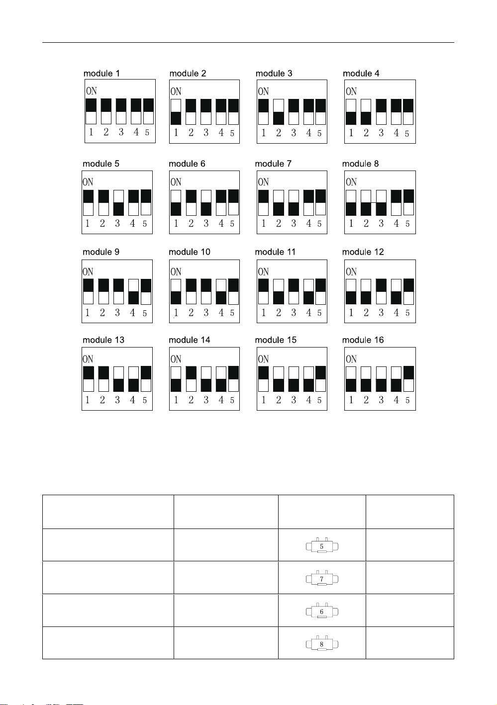
7.6 Setup of Toggle Switches on the Motherboard
Five-bit toggle switches are used for indicating hardware address (1~16) of modules, with
module No. displayed in turn on the panel as Module 1, Module 2, ……, Module 16. Toggle
switches 1,2,3,4 and 5 are binary codes, with 1 for the lowest bit and 5 for the highest bit.
Comparison drawings are as follows (Caution: only in the condition of power supply shutoff
can toggle switches be set):
21
Page 26
A Series Inverter Modular Air-cooled Chiller (Heat Pump)
Note: the black block represents where the projecting lever of the toggle switch is.
7.7 Jumpers
When it is required to replace the main board, be sure the main board can match with the
applicable jumpers.
Table 7.7.1 Jumpers List
Model Code
LSQWRF35VM/NaA-M
LSQWRF60VM/NaA-M
LSQWRF65VM/NaA-M
LSQWRF70VM/NaA-M
Jumper No
4202021905
4202021907
4202021906
4202021908
22
Matched
Compressor
QXAS-
H80zN345H
QXAS-
H80zN345H
QXAS-
H80zN345H
QXAS-
H80zN345H
Page 27
A Series Inverter Modular Air-cooled Chiller (Heat Pump)
8 Commissioning and Maintenance
The unit shall be maintained periodically by the skilled servicemen from Gree or a designed
person under our professional guide to guarantee the unit operates reliably in a long term.
8.1 Check before Startup
Please finish the following steps before staring the system.
(1)Before energization, be sure the insulation resistance between the wiring terminal and
ground complies with the local codes and regulations and check if the motor meets
the insulation requirement with a resistance meter.
(2)Check if all connenctions are in good condition and clean.
(3)Close the main power switch.
(4)Check if the voltage between terminals keeps balance within deviation of 2%.
(5)Be sure the power cord is capable of carrying the rated current on the nameplate.
(6)Be sure all valves of water and refrigerant pipeline are placed properly.
(7)Reset all hand reset control elements.
Be sure all sensor are placed installed properly.
8.2 Requirements on Water Quality and Cleaning
Be sure to open the water pump after the water system has been flushed times and the
water quality has met the requirements and meanwhile be sure the water flow rate and
pressure are within the allowable range.
The industrial water generates little scale when used as the refrigeration medium while the
well or river water will generate much more scale and sands which would reduce the flow rate
of the evaporate and cause freezing. Therefore, the well or river water must be firstly treated
with the water softening equipment and analyze the PH, heat conductivity, Cl ion, and S ion
before use.
Table 8.2.1 Water Quality
Basic
items
Water Quality Requirement
Cold/hot water Trend
Items
Circulating
water
Makeu-
p water
PH(25℃) 6.8-8.0 6.8-8.0 6.8-8.0 0
Electrical conductivity
(25℃)
-
Cl
2-
SO
4
μs/cm
mg(Cl-)/L
mg(SO
4
2-
)/L
<400 <300 0 0
<50 <50 0
<50 <50 0
Acid consumption
(PH4.8)
Total hardness
mg(CaCO
mg(CaCO
3
3
)/L
)/L
<50 <50
<70 <70
23
Corro-
sion
Sc-
ale
0
0
Page 28
A Series Inverter Modular Air-cooled Chiller (Heat Pump)
Total
hardn-
ess
Fe
S
NH
SiO
mg(Fe)/L
2-
+
4
2
mg(S2-)/L
mg(NH
+
)/L
4
mg(SiO2)/L
<1.0 <0.3 0 0
Undetecta-
ble
Undet-
ectable 0
<1.0 <0.3 0
<30 <30
0
NOTE:“○”indicates possible corrosion or scaling.
Even if the water qualify is under the strict control, calcium dioxide or other minerals will still
form on the surface of the heat exchanger which will affect the heat exchange efficiency and
be eliminated by formic acid, lemon acid, acetic acid or other organic acid.
Therefore, the pipe system should be cleaned periodically. Oxalic acid, acetic acid and
formic acid can be used as the organic cleaning agent, but the strong chloracid is not allowed
as it will corrode the copper tube of the heat exchanger and then lead to water and refrigerant
leakage.
■ Preparation of Materials and Tools
Several bags of environmental friendly scale remover, or similar cleaning liquid.
■ Cleaning Instructions
Step 1: estimate the required amount of scale remover in accordance with the system water
volume and severity of scaling.
Step 2: add the scale remover to the water tank and the scale remover.
Step 3: start through the contactor the water pump every 10 minutes and spread the scale
remover in water more quickly and widely.
Step 4: after that, follow the steps below:
(1)let the water pump run for another 1-2 hours.
(2)1-2 hours later, change the cleaning solution to anti-rusting agent. Then, drain the
water system and check the water quality. If water is cloudy, then it indicates the
cleaning effect is satisfactory.
(3)open the water inlet to see if scale on the shell and tube has been removed. If not,
clean the shell and tube separately again by the skilled serviceman and then rinse
them. If there is still sand, scale and other foreign matters at the bottom of the shell
and tube, let cleaning solution in from the inlet pipe and then let the foul water out
through the drain outlet.
(4)fully charge the water system and let it run for another 1-2 hours.
(5)stop the unit to drain up waste solution. If impossible, drain it with making up water at
the same time until all waster solution has been drained out completely (at this time
water is transparent and PH is 7).
(6)repeat 4 and 5.
(7)clean or change the filters in the water system.
(8)see if the difference between the entering and leaving water temperature is improved.
24
Page 29

A Series Inverter Modular Air-cooled Chiller (Heat Pump)
■ Precautions
(1)Although the cleaning agent is innocuous,care also should be taken not to let it spill
into eyes.
(2)The serviceman with injuries on the hand is not allowed to take this task.
Check the running status before and after cleaning, summarize the cleaning effect and
record the running data before and after cleaning.
8.3 Trial Run
(1)When the unit has not been used for a long period or the ambient temperature is below
5℃, keep the unit energized at least 8 hours before startup to preheat the crankcase
of the compressor so as to evaporate the liquid refrigerant inside the compressor
which otherwise would cause adverse effect on the compressor.
(2)Be sure valves are opened properly to prevent the compressor from being damaged by
the abnormal high pressure.
(3)Check the power supply and insulation conditions, and see initial settings of each
control and protection element are satisfactory, and then record relative records.
(4)Turn on the wired controller to check the error record. If any error exists, eliminated it
before restarting the unit.
(5)When a single unit has run stably, check the entering and leaving water temperature
difference, and adjust the water damper to make the temperature difference reach
2.5~6℃ and then record related data.
(6)When all units have run stably, check the entering and leaving water temperature
difference of each on, and adjust the water damper to make the temperature
difference reach 2.5~6℃ and then record related data.
(7)When all loads have been started and all units have run stably for one hour, check the
air conditioning and water temperature and see if they can meet the client’s
requirement and then record related data.
8.4 Routine Startup/Shutdown
It is recommended to start the system through the wired controller in the sequence of the
water pump first and then the main unit, and stop the system in a reverse sequence.
When the unit is not used for a long term or temperature is below 5℃, remember to keep the
unit energized at least 8 hours before startup to preheat the crankcase of the compressor so
as to evaporate the liquid refrigerant inside the compressor which otherwise would cause
adverse effect on the compressor.
When the function of the auxiliary electric heater is activated through the control panel, if the
ambient temperature is quite low and out of the nominal heating range, the control panel will
tell “As ambient temperature is low, startup is not allowed”. At this point, the auxiliary electric
heater will work, with the running indicator lighting on, the water pump running but the
compressor stopped.
When the function of the auxiliary electric heater is deactivated through the control panel, if
the ambient temperature is quite low and out of the nominal heating range, the control panel
25
Page 30
A Series Inverter Modular Air-cooled Chiller (Heat Pump)
will tell “As ambient temperature is low, startup is not allowed”. At this point, the auxiliary
electric heater will not work, with the running indicator lighting off and both the water pump and
compressor stopped.
NOTE
When the unit is ready to perform heating but water temperature is below 20℃, in order to
keep stable and reliable operation, please do not start the terminal units until water
temperature goes up to 35℃.
8.5 Maintenance to the Main Parts
(1)During normal operation, the water pump is under the control of the main unit.
However, when flushing the water system, do not let the main unit control the water
pump.
(2)Do not start the unit until the water system has drained completely.
(3)Do not manually restart the unit until the stop interval exceeds 6 minutes.
8.6 Maintenance during Long-term Downtime
When the chiller is going to be stopped for a long period, maintenance listed below shall be
performed:
(1)Take the leakage test for the refrigerant tube. If leakage occurs, eliminate it.
(2)Maintain the water pump and air conditioning divides in accordance with the
suggestions provided by the manufacturer.
(3)Drain the water system by opening the discharge valve (especially in winter) to avoid
frostbite on the shell and tube.
(4)Switch off the power supply of the chiller and the water pump.
(5)Clean and dry the inside and outside surface of the chiller. Then, cover it against dust.
8.7 Startup after Long-term Shutdown
Preparations shall be taken when starting up the chiller which has not been used for a long
period.
(1)Completely check and clean up the chiller.
(2)Clean the water piping system.
(3)Check the water pump.
(4)Tighten all connectors.
(5)Take the leakage test for all piping. If leakage occurs, eliminate it.
(6)Regulate the water flow through the balance valve and check the water pressure.
(7)Check if the fan rotates properly.
(8)Check if the system vibration and noise are acceptable.
8.8 Parts Replacement
Only parts supplied by Gree can be replaced instead of similar parts supplied by others.
26
Page 31
A Series Inverter Modular Air-cooled Chiller (Heat Pump)
8.9 Refrigerant Charging
Refrigerant charging should be done based on the discharge and suction pressure. An air
tight test must be taken on the condition refrigerant leaks or some part is required to be
replaced. Refrigerant charging comes into two cases stated below.
◆ Complete charging
In this case, take a leakage test by charging hi-pressure nitrogen (15~20kg) or refrigerant
into the system. If soldering is required, note that gas inside the system must be expelled
firstly. The whole system must be dried and vacuumed prior to charging.
(1)Connect the manifold gauge.
(2)Vacuum the system with the vacuum pump.
(3)After the system pressure reaches the required value (<80Pa) for more than 30
minutes and keeps below 100Pa, charge refrigerant at the low pressure side as per
the rated specification on the nameplate.
(4)Refrigerant charge will be affected by the ambient temperature. When charged
refrigerant is under the required amount, add in accordance with the other charging
case stated below.
◆ Adding
Connect the refrigerant charging port at the lower pressure side to the refrigerant tank and
install a manifold gage.
(1)Circuit the chilled water and start up the unit.
(2)Charge refrigerant vapor into the system slowly and check the suction and discharge
pressure.
WARNING
(1)When performing the leakage and air tight test, never charge oxygen, acetylene and
other flammable and toxic gases but only hi-pressure air, nitrogen or refrigerant.
(2)Mineral scale on the surface of the heat exchanger will affect the heat exchanging
efficiency and increase the water resistance and lower the refrigeration capacity.
Therefore, it should be cleared away through dilute acid. Note that contents of
different water quality vary and should be treated with different type of acid by the
qualified chemical company.
8.10 Removal of the Compressor
Please take the steps below when the compressor is required to be removed.
(1)Cut off the power supply.
(2)Recover the refrigerant in a reasonable speed to prevent oil from being drawn out.
(3)Remove the power cord and the temperature sensor.
(4)Unsolder the soldering spots of the suction and discharge lines.
(5)Remove the screw bolts of the compressor and check the oil quality and accumulator.
(6)Remove the compressor.
27
Page 32
A Series Inverter Modular Air-cooled Chiller (Heat Pump)
(7)Clean up the pipeline.
8.11 Freeze Protection
When the flow passage of the shell-and-tube heat exchanger is frozen up, it would cause
serious damage to the heat exchanger, such as cracking and leakage which are out of
warranty, therefore, the user should take measures stated below for freeze protection:
(1)In order to make sure the unit can automatically perform defrosting under low
temperature, the water pump must be interlocked with the unit.
(2)(1) Under subzero condition, when the unit is required to perform cooling, anti-freeze
liquid should be added into the water system based on the table below.
(3)Under subzero condition, when the unit is not required to perform cooling for a short
term, the unit should be powered on; when the unit is not required to perform cooling
for quite a long term, disconnect the power supply and then drain the shell and tube
completely.
Table 8.11.1 Thermal and Physical Properties of the Glycol Solution
Quality Concentration Initial Freezing Temperature Density
16 -7 1020
19.8 -10 1025
23.6 -13 1030
27.4 -15 1035
31.2 -17 1040
35 -21 1045
38.8 -26 1050
42.6 -29 1055
46.4 -33 1060
Notes:
(1)This table is cited from Design Manual for Practical Refrigeration Engineering
published by China Architecture Industry Press. If physical data of the glycol has been
provided by the manufacturer, it always prevails.
(2)Once the glycol is taken as the second refrigerant, its initial freezing temperature of the
glycol solution should be 2~3℃ lower than the lowest environment temperature.
8.12 Rountine Maintenance
Routine maintenance shall be performed periodically by the qualified technician so as to
extend the service life of the unit and lower the possibility of occurrence of faults.
Record weekly the running status of the unit to facilitate troubleshooting for the servicemen.
■ Daily Maintenance
(1)Check the circulating water pump and the flow rate.
(2)Check the voltage and power supply.
28
Page 33

A Series Inverter Modular Air-cooled Chiller (Heat Pump)
■ Weekly Maintenance
(1)Check the main unit, like if the compressor runs with abnormal noise, if the distribution
box is attached securely and if the pipeline generates abnormal vibration or leakage.
(2)Record key parameters, like pressure, pressure etc.
■ Quarterly Maintenance
(1)Check the electric wiring and electric insulation.
(2)Check and adjust the set point of the temperature.
■ Yearly Maintenance
(1)Check valves and pipeline of the water system. If necessary, clean the filter and
analyze the water quality. If the water circuit needs to be cleaned, please consult the
assistance of the qualified personnel.
(2)Clean the corrosive surface and paint it again, and check if the door of the electric
control cabinet is tightly closed.
(3)Check if the pipeline is secured and so the water pump and fittings. Additionally, check
if the refrigerant charge is sufficient, if not, add some.
(4)Perform the items for weekly maintenance.
(5)Check if the control device is set and acts properly.
(6)Check if the refrigerant pipe is attached securely.
(7)Check if the refrigerant pipe is attached securely.
8.13 Precautions
(1)Take periodic maintenance to the unit to guarantee normal operation.
(2)Once refrigerant leaks, shut down the unit immediately and contact the serviceman. No
open fire is allowed in that refrigerant will decompose into toxic gas.
(3)Switch off the main power supply in case of a fire hazard and extinguish it with effective
measures.
(4)The working environment shall be far away from the inflammable substance, such as
petroleum and alcoholic etc. to avoid explosion.
(5)The unit is allowed restarted only after any malfunction is eliminated, otherwise
refrigerant or chilled water would leak, in which case, it is imperative to turn off all
switches or the main power supply.
(6)Do not short-circuit the protection device, otherwise it would cause some malfunction.
29
Page 34
A Series Inverter Modular Air-cooled Chiller (Heat Pump)
9 Troubleshooting and After-sales Service
9.1 Troubleshooting Measures
Error Possible Causes
Shutdown against high
pressure protection of the
compressor
Shutdown against
overloading of the
compressor motor
1.Uncomplete vacuuming.
2.Too high envivornment
temperature.
3.Condenser fins are dirty
and there are blockages.
4.Inadequate condensing air
flow and the condenser fan
failed.
5.Failed high pressrue
cutoff.
6.Overcharged refrigerant.
1.The voltage is too high or
too low.
2.The discharge pressure is
too high or too low.
3.The return water
temperature is too high.
4.The overloaded element is
faulty.
5.The enviornment
temperature is too high.
6.There is phase loss for the
compressor.
7.The compressor motor is
short-circuited.
Troubleshooting Measures
1.Revacuum the system and
recharge refrigerant.
2.Improve ventilation.
3.Clean condenser fins.
4.Repair the condenser fan.
5.Check the high pressure
switch.
6.Check the refrigerant
charge and discharge some
refrigerant.
1.Check if the voltage is or
no less than 80% and the
phase difference does not
exceed ±30%.
2.Check discharge pressure
and find out causes.
3.Check return water
temperature and find out
causes.
4.Check the compressor
current.
5.Improve ventilaiton.
6.Check the three phase
resistances.
Shutdown against low
pressure protection of the
compressor
1.The electrostatic
expansion valve is faulty.
5.The low pressure cutoff is
faulty.
3.Refrigerant is insufficient.
4.The entering chilled water
temperature is 5.lower than
the rated.
6.The chilled water flow is
too low.
30
1.Replace the coils or even
the valve body.
2.Check the low pressrue
cutoff.
3.Check and charge
refrigerant.
4.Check if the chilled water is
down-temperature.
5.Adjust the chilled water
flow.
Page 35

Failed startup of the
compressor
A Series Inverter Modular Air-cooled Chiller (Heat Pump)
1.The overcurrent relay
tripped off and the fuse was
burnt out.
2.The control circuit was
open.
3.There is no current.
4.Low/high pressure
protection.
5.The contact coils is burnt
out.
6.The water flow is open-
circuited.
7.The wireless controller
raised the alarm signal.ON/
OFF time setting by the
1.Replace it.
2.Check wiring of the control
system.
3.Check the power supply.
4.See corresponding
statement above.
5.Replace it.
6.Check the water system.
7.Check the alarm type and
take corresponding
corrective measure.
8.Check and reset it.
wireless controll is incorrect.
8.The sensed temperature
exceeded the rated.
Temperature sensor
protection
Pressure transducer error
Flow switch protection
1.The buld plug and the
main board plug were
connected incorrectly.
2.The temperature bulb was
damaged.
3.The main board was
damaged.
1.The pressure sensor is
open-circuited.
2.The pressure sensor is
short-circuited.
3.The pressure sensor is
damaged.
1.The water pump has not
started.
2.The water flow is too low.
3.The water flow switch was
damaged.
4.There was air inside the
waer system.
1.Check if the bulb plug was
connected to the correct
main board plug.
2.Replae it.
3.Replace it.
1.Check the circuit of the
pressrue sensor.
2.Replace it.
1.Start the water pump.
2.Adjust the water flow.
3.Adjust the water flow.
4.Dispel air inside the water
system.
31
Page 36

A Series Inverter Modular Air-cooled Chiller (Heat Pump)
1.The entering and leaving
Protection against the failed
4–way valve
water temperature sensor
fell off or installed incorreclty.
2.The 4–way valve was
damaged.
1.Check if the entering and
leaving water temperature
sensors were installed
correctly and if silica gel at
the probe for heat conduction
was applied properly.
2.Replace it.
Protection against the failed
compressor IPM module
Failed diischarge
temperature sensor
1.The voltage suddenly
dropped.
2.The compressor drive
board was damaged.
1.Tow low water tempeature.
2.The discharge
temperature sensor fell off.
1.Check if it occured before
protection.
2.Replace it.
1.Decrease the load to
improve the water
temperature.
2.Check if the discharge
temperature sensor installed
correctly.
9.2 After-sales Service
When the unit in warranty has a quality issue or fails to operate properly under the allowable
operation condition, please contact the local sales representative for free service.
The user is required to designate personnel to take charge of the unit following the
instructions covered in this manual, otherwise any maintenance cost caused by the improper
operation will be at the user’s expense.
32
Page 37
A Series Inverter Modular Air-cooled Chiller (Heat Pump)
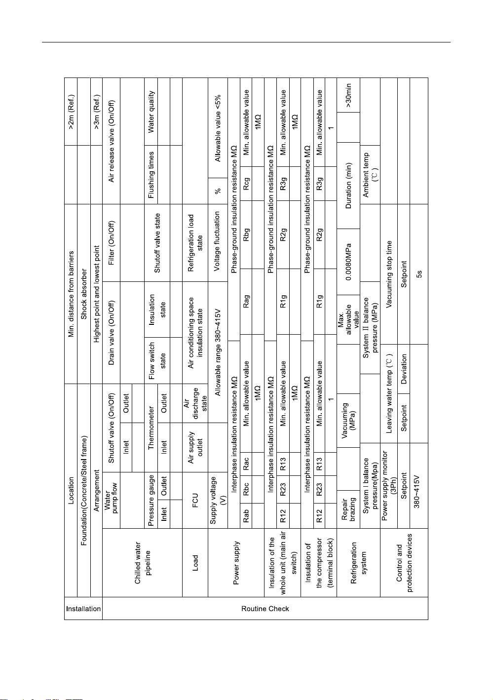
Appendix A: Inspection Records Prior to Commissioning
33
Page 38
A Series Inverter Modular Air-cooled Chiller (Heat Pump)
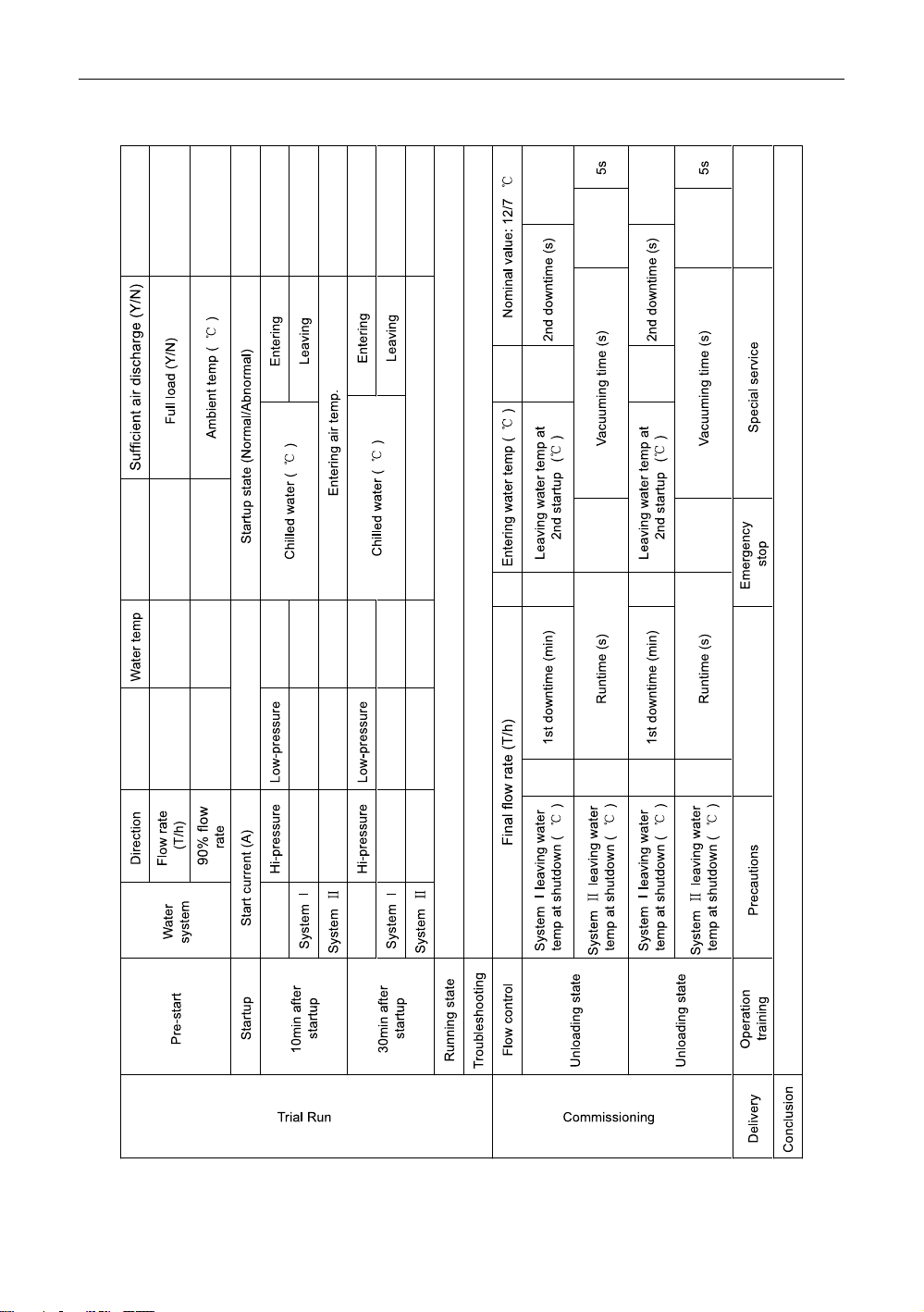
Appendix B: Trial Run and Commissioning Records
34
Page 39
 Loading...