

Gree HW18024PNa-D, HW18036PNa-D, HW18042PNa-D, HW18048PNa-D Owner's Manual
Change for life
Thank you for choosing Commercial Air Conditioners, please read this
owner’s manual carefully before operation and retain it for future reference.
For R410A Series
Unitary Ducted Split AC
Commercial Air Conditioners
Owner's Manual

Contents
Safety Considerations ...................................................................................1
1. Installation of the Wired Controller ............................................................2
2. Wiring Terminals of the Wired Controller ...................................................2
3. Main Page .................................................................................................3
4. Function Setting.........................................................................................3
4.1 “ON/OFF” .............................................................................................3
4.2 “Mode” ...................................................................................................4
4.3 “Fan” ...................................................................................................... 4
4.4 “▼/▲” (Temperature Adjustment) ..........................................................4
4.5 “SET” (Parameters/Functions View and Setting) ...................................5
4.6 “Enter/Hold” ...........................................................................................9
4.7 Lock Function ......................................................................................10
4.8 Error Display ........................................................................................ 10
5 Installation Instructions ............................................................................. 11
5.1 Physical Dimension ............................................................................ 11
5.2 Installation Recommendations ...........................................................12
5.3 Installation ..........................................................................................13
Unitary Ducted Split AC
1
Safety Considerations
Improper installation, adjustment, alteration, service, maintenance, or use can cause explosion,
fire, electrical shock, or other conditions which may cause death, personal injury, or property
damage. Consult a qualied installer, service agency, or your distributor or branch for information or
assistance. The qualied installer or agency must use factory--authorized kits or accessories when
modifying this product. Refer to the individual instructions packaged with the kits or accessories
when installing. Follow all safety codes. Wear safety glasses, protective clothing, and work
gloves. Use quenching cloth for brazing operations. Have re extinguisher available. Read these
instructions thoroughly and follow all warnings or cautions included in literature and attached to
the unit. Consult local building codes and National Electrical Code (NEC) for special requirements.
Recognize safety information. This is the safety--alert symbol .When you see this symbol on the
unit and in instructions or manuals, be alert to the potential for personal injury. Understand these
signal words; DANGER, WARNING, and CAUTION. These words are used with the safety--alert
symbol. DANGER identies the most serious hazards which will result in severe personal injury
or death. WARNING signies hazards which could result in personal injury or death. CAUTION is
used to identify unsafe practices which may result in minor personal injury or product and property
damage. NOTE is used to highlight suggestions which will result in enhanced installation, reliability,
or operation.
WARNING
ELECTRICAL SHOCK HAZARD
Failure to follow this warning could result in personal injury or death.
Before installing, modifying, or servicing system,main electrical disconnect switch must be in
the OFF position. There may be more than 1 disconnect switch. Lock out and tag switch with a
suitable warning label.
This product must not be disposed together with the domestic waste.
This product has to be disposed at an authorized place for recycling of
electrical and electronic appliances.
Unitary Ducted Split AC
2
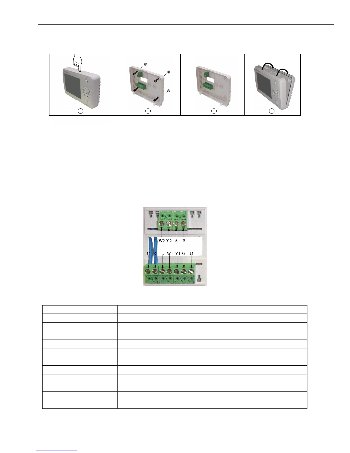
1. Installation of the Wired Controller
1 2 3 4
Fig.1 Installation Diagram
Step 1: Press the button at the top of the wired controller to remove the front panel and the
bottom plate.
Step 2: Reinstall the bottom plate in accordance with the locating holes either shown in the
gure above or decided by the user.
Step 3: Conduct the wiring and see section 2 for more details.
Step 4: Reinstall the front panel.
2. Wiring Terminals of the Wired Controller
Fig 2 Wiring Terminals Diagram
Table 1
Terminal Code Description
C 24 Volt (Neutral)
R 24 Volt Emergency (Hot)
O Four-Way Valve
G Indoor Unit
Y1 Compressor 1
Y2 Compressor 2(Reserved)
W1 Auxiliary Electric Heater 1
W2 Auxiliary Electric Heater 2
L Temperature Sensor Error Output
A 485 Communication Port
B 485 Communication Port
Unitary Ducted Split AC
3
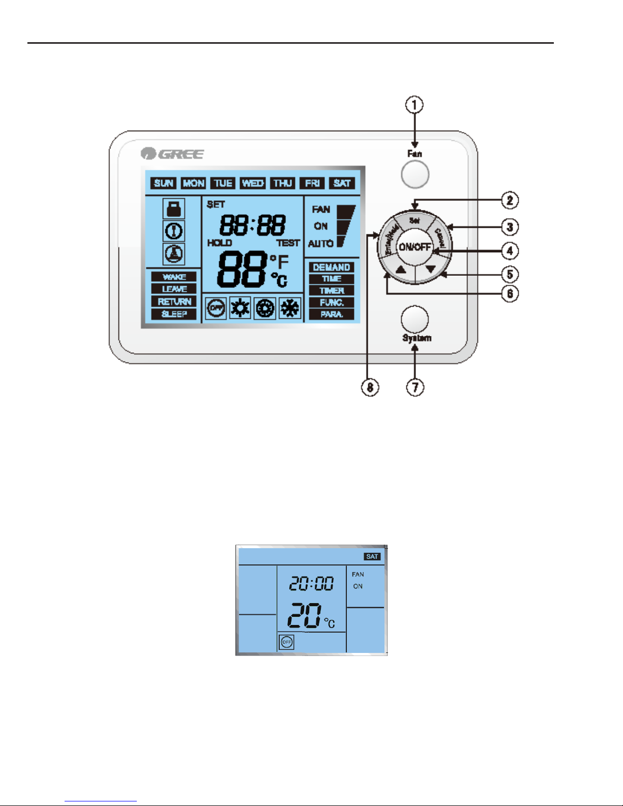
3. Main Page
Fig.3 Main Page
①
“Fan” ③ “Cancel” ⑤ “▼” ⑦ “Mode”
②
“Set” ④ “ON/OFF” ⑥ “▲” ⑧ “Enter/Hold”
4. Function Setting
4.1 “ON/OFF”
The controller can be turned on/off by pressing this button, with the corresponding ON/OFF
symbol displayed.
Fig.4
Unitary Ducted Split AC
4
4.2 “Mode”
One among various mode options can be selected by pressing the “Mode” button
● As for the cooling only unit, the switchover order of mode options is: E-HEATER→COOL.
● As for the cooling and heating unit, the switchover order of mode options is: HEAT→
E-HEATER →COOL
Note: the unit type is identied by the main board of the unit.
Fig. 5
4.3 “Fan”
It is available to select the desirable fan option by pressing the “Fan” button
● Under the “FAN ON” option, the fan will always keep running.
● Under the “FAN AUTO” option, the fan will be automatically shut down or started up in
accordance with the actual Mode and temperature.
Fig. 6
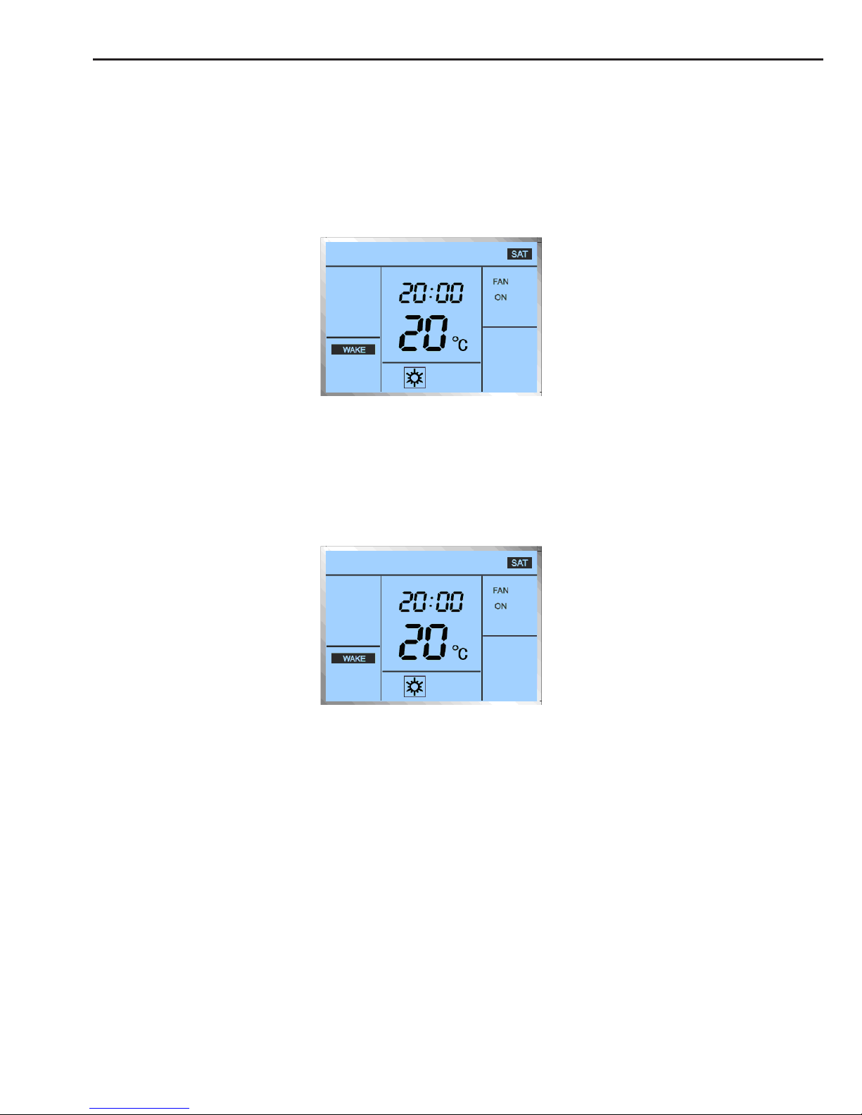
4.4 “▼/▲” (Temperature Adjustment)
Under the main page, the temperature for the current Mode can be adjusted by pressing the
“▼/▲” button.
● During temperature adjustment, the temperature value will blink, with the symbol “SET”
displayed.
● After the adjustment, it will automatically back to the main page and display the current
environment temperature.
Unitary Ducted Split AC
5
Fig. 7
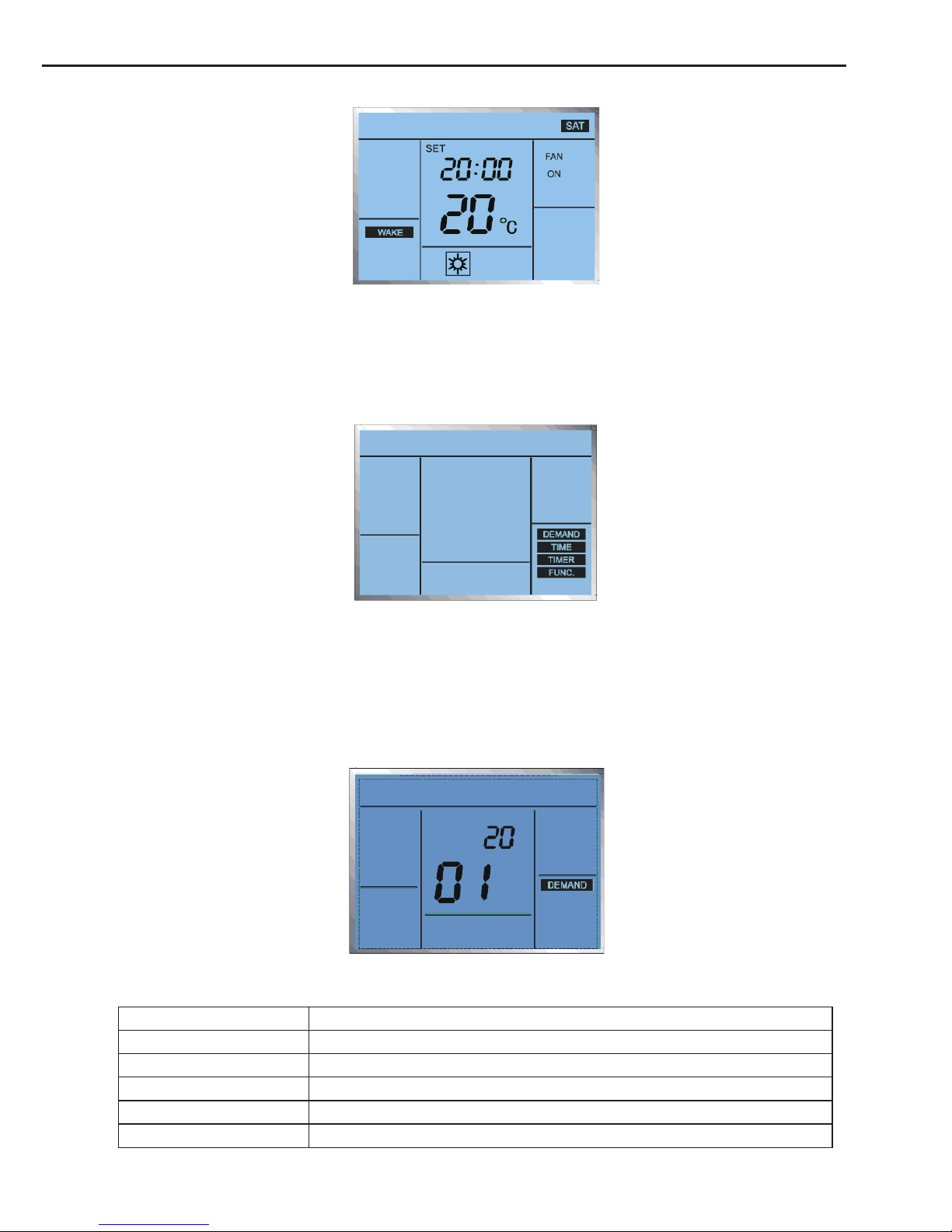
4.5 “SET” (Parameters/Functions View and Setting)
It is available to go the parameters/functions view and setting page by pressing the “Set”
button, and then desired option can be selected by pressing the “▼/▲” button, nally go to the
corresponding view and setting page by pressing the “Enter/Hold” button.
Fig.8 Parameters/Functions View and Setting
4.5.1 “DEMAND”
After accessing to the “DEMAND” page, it is available to select the desired parameter by
pressing the “▼/▲” button.
The upper value indicates the desired parameter, while the lower value indicates the parameter
No.
Fig.9
Table 2
Parameter No. Parameter Description
01 Compressor Runtime
02 Opening Angle of the Electronic Expansion Valve
03 Outdoor Environment Temperature
04 Tube Inlet Temperature of the Outdoor Unit
05 Tube Midway Temperature of the Outdoor Unit
Unitary Ducted Split AC
6
06 Tube Outlet Temperature of the Outdoor Unit
07 Discharge Air Temperature of the Outdoor Unit
08 Preset Frequency
09 Running Frequency
10 IPM Radiator or IPM Temperature
● This page can quit by pressing the “Enter/Hold” button,
● The accumulated “Compressor Runtime” can be cleared by pressing the “Mode” button for
ve seconds.
Note: when the accumulated “Compressor Runtime” exceeds 1500 hours, a symbol on the main
page will be displayed to remind the user clearing the runtime.
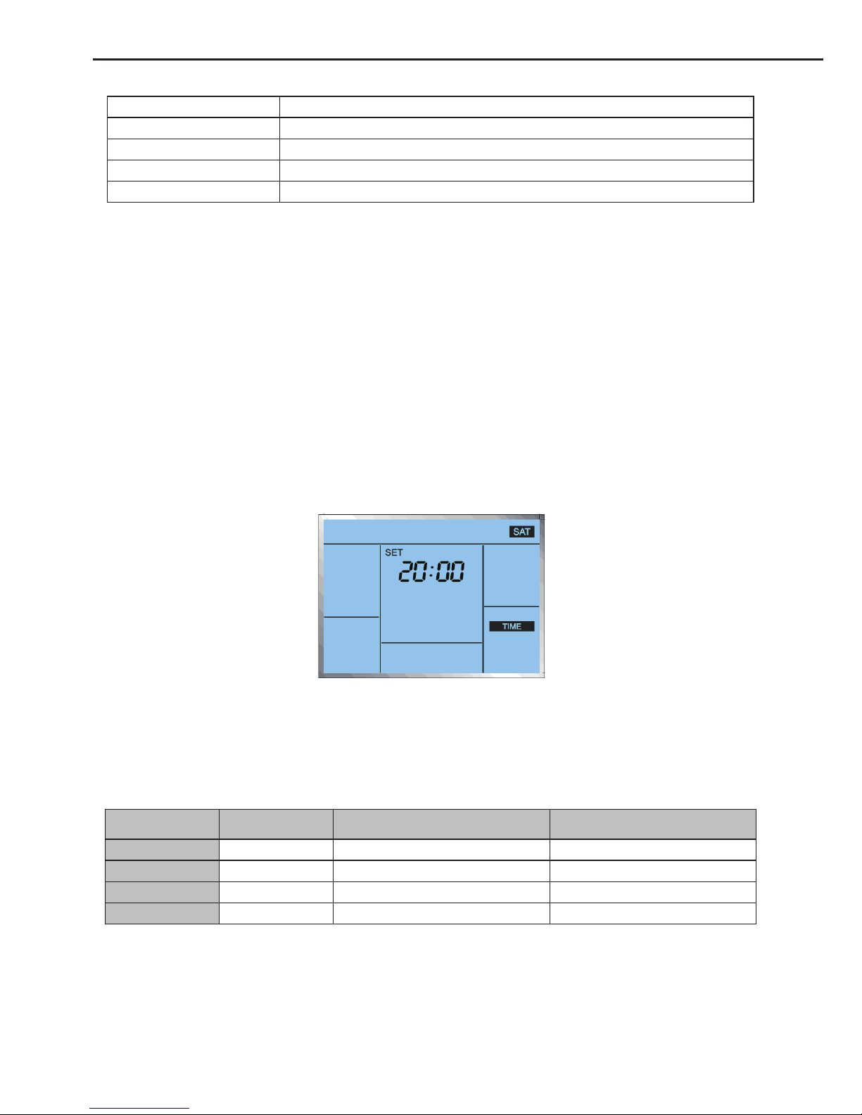
4.5.2 “TIME”
After going into the “TIME” page, it is available to adjust the time.
● Switch to the time value in the order of DAY →HOUR →MINITE,
● Adjust the blinking value by pressing the “▼/▲” button,
● After the MINUTE is set, press the “Enter/Hold” button for conrmation to make this setting
come effective and back to the previous interface.
If the setting is canceled prior to the conrmation, then the related parameter will not be saved
and come into effect.
Fig.10
4.5.3 “TIMER”
It is capable of timing four periods for each day of one week,
For instance:
Table 3
No. Period Cooling Temperature
Heating Temperature
(Auxiliary Heating)
Period 1 06:00 24
℃
21
℃
Period 2 08:00 28
℃
17
℃
Period 3 18:00 24
℃
21
℃
Period 4 22:00 26
℃
17
℃
When the unit is currently under the cooling mode, the temperature will be set to
24℃ automatically at 06:00, 28℃ at 8:00, 24℃ at 18:00 and 26℃ at 22:00.
When the unit is currently under the heating or auxiliary heating mode, the temperature will be
set to 21℃ automatically at 06:00, 17℃ at 8:00, 24℃ at 21:00 and 17℃ at 22:00.
①
After going to this function page, the day (like, “SAT”) will blink and then adjust it through the
 Loading...