

Page 1
Condensing Unit Service Manual
T1/R410A/60Hz
(GC201408-І)
Page 2

PRODUCT ..................................................................................................... 2
1 MODELS LIST .......................................................................................................... 2
1.1 Indoor Unit .................................................................................................................................... 2
2 NOMENCLATURE ..................................................................................................... 2
2.1 Indoor unit .....................................................................................................................................2
3 FUNCTION ................................................................................................................ 3
4 PRODUCT DATA ....................................................................................................... 4
4.1 Product Data at Rated Condition ..................................................................................................4
4.2 Operation Range ........................................................................................................................... 4
4.3 Electrical Data .............................................................................................................................. 5
CONTROL ...................................................................................................... 7
1 OPERATION FLOWCHART ...................................................................................... 7
1.1 Cooling/Dry Operation ................................................................................................................... 7
2 MAIN LOGIC .............................................................................................................. 8
2.1 Cooling Mode (for Cooling Only and Heat Pump) ......................................................................... 8
2.2 Dry Mode ....................................................................................................................................... 9
2.3 Fan Mode ...................................................................................................................................... 9
3 CONTROLLER ....................................................................................................... 10
3.1 wireless remote controller ..........................................................................................................10
3.2 Wired Controller (Chosen Accessory Part) ................................................................................14
INSTALLATION ............................................................................................ 19
1 INDOOR UNIT INSTALLATION ............................................................................... 19
1.1 Installation of Ceiling Type ..........................................................................................................19
3 REFRIGERATION PIPING WORK .......................................................................... 22
3.1 Refrigeration Piping Work Procedures ........................................................................................ 22
3.2 Caution in Connecting Pipes ....................................................................................................... 26
3.3 Specication of Connection Pipe ................................................................................................26
4 ELECTRIC WIRING WORK ..................................................................................... 26
4.1 Wiring Principle ...........................................................................................................................26
4.2 WIRING DIADRAM ....................................................................................................................28
4.3 Electric Wiring Design ................................................................................................................. 29
MAINTENANCE ........................................................................................... 31
1TROUBLE TABLE(Only for oor ceiling) ................................................................... 31
2 FLOW CHART OF TROUBLESHOOTING ............................................................. 31
2.1 Air ow volume from air outlet of unit is abnormal ......................................................................31
2.2 The unit can not start up for cooling ........................................................................................... 32
2.3 Poor cooling effect .......................................................................................................................33
2.4 Noise or abnormal vibration of unit .............................................................................................34
4 DISASSEMBLY AND ASSEMBLY PROCEDURE OF MAIN PARTS ....................... 35
5 EXPLODED VIEWS AND PART LIST ..................................................................... 38
CONTENTS
Page 3

1
Condensing Unit
Service Manual
PRODUCT
PRODUCT
Page 4
2
Condensing Unit
Service Manual
PRODUCT
PRODUCT
1 MODELS LIST
1.1 Indoor Unit
Refrigerant
Model Nominal Capacity Power Supply
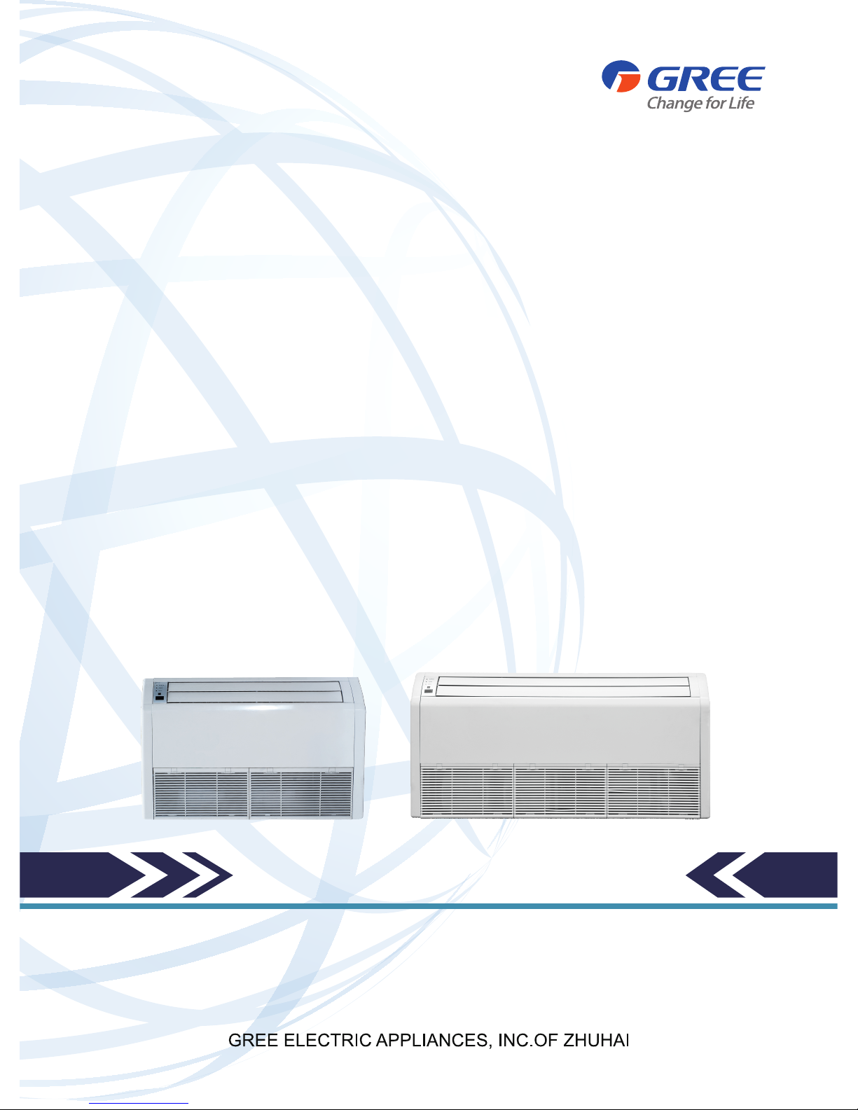
Appearance
Model Name Product Code Cooling(Ton) Heating(Ton) V, Ph, Hz
R410a
HNTF24/A-D EM116N0760 2 2
220V-230v
1PH 60HZ
HNTF36/A-D EM116N0780 3 3
HNTF48/A-D EM116N0800 4 4
HNTF60/A-D EM116N0820 5 5
Note:1 Ton =12000Btu/h = 3.517kW
2 NOMENCLATURE
2.1 Indoor unit
HN T F 36/ A D
1 2 3 4 5 6
NO Description Options
1 Unit Series Type HN: Split Series
2
Unit Type
U=Match Outdoor Unit
F=Duct Type
K=Cassette Type
T= Ceiling Type
3 / /
4
Nominal Cooling Capacity
018=18000Btu/h
024=24000 Btu/h
030=30000 Btu/h
036=36000 Btu/h
042=42000 Btu/h
048=48000 Btu/h
060=60000 Btu/h
5 Product Serial Number A, B, C...
6 Power Supply
D:1Ph,208/230V,60Hz
K:1Ph,220/240V,60Hz
M:3Ph,380/415V,50Hz
F:3Ph,208/230V,60Hz
Page 5
3
Condensing Unit
Service Manual
PRODUCT
3 FUNCTION
Function
Description
Memory function
when unit restart after power off, it will run on former status,
the mode and parameter are kept the same
Remote control function
wireless controller and remote controller can be opted, and the
maximum control distance of remote controller is 10m.
Timing function it can timing ON/ OFF separately, meanwhile, it also can timing on circularly
Self-diagnosis with alarm function once unit has malfunction, the malfunction code will be indicated
Sleep function
it can self control for saving energy in energy saving mode.
Automatic function
the fan of indoor unit can adjust fan speed automatically based on
actual demand when cooling or heating under automatic mode
Cool air proof function
the fan starts only when the temperature of indoor unit heat exchanger
is higher than indoor temperature under heating mode
Weekly Timer
Centralized Control and Week Timer Functions: The centralized controller and
the weekly timer are integrated in the same wire controller. The system has both
the centralized control and the week timing functions. Up to 16 sets of units can
be controlled simultaneously by the centralized controller (weekly timer). The
weekly timer has the function of invalidating the lower unit. The weekly timing
function is able to realized four timing ON/OFF periods for any unit every day, so
as to achieve fully automatic operation. No timing control can be set for holidays.
High/low pressure protection
when suction pressure is too low or discharge pressure is too high,
compressor will stop and unit display malfunction code
Overload protection
compressor has its own overheat protection, once the temperature
of compressor is higher than allowable level, compressor will stop
and only when temperature recovery, compressor restart
Over current protection
once the current of compressor is higher that normal level,
compressor will stop and unit display malfunction code
Discharge high
temperature protection
once the discharge temperature of compressor is higher than allowable
value, compressor will stop and unit display malfunction code
Reverse (open) phase protection
once the phase sequence of power supply is incongruent
or the phase is absent, unit can’t work
Anti-high temperature protection once the heat exchanger temperature of indoor unit is too high, compressor stop.
Timing ON/OFF display display and timing turn ON/OFF time (only with wired controller have this function)
Fan speed display
display the speed (high, medium, low) of fan(only
with wired controller have this function)
Function model display
cooling mode, dehumidifying mode, heating mode, fan mode
(only with wired controller have this function)
Testing display
display testing mode(only with wired controller have this function)
Temperature display
display room temperature and set temperature (with wired
controller or remoter board have this function)
Page 6
4
Condensing Unit
Service Manual
PRODUCT
4 PRODUCT DATA
4.1 Product Data at Rated Condition
HNTF24/A-D HNTF36/A-D HNTF48/A-D HNTF60/A-D
Product Code EM116N0760 EM116N0780 EM116N0800 EM116N0820
Blower
Diameter(inch) 5 5 6 6
Width(inch) 4 4 7 7
Coil Drain Connection
FPT(inch)
7/8 7/8 7/8 7/8
Liquid(inch) 3/8 3/8 3/8 1/2
Suction(inch) 5/8 3/4 7/8 7/8
Electrical Data
Voltage(V) 220-230 220-230 220-230 220-230
Min Circuit
Ampacity (A)
13 13 13 13
Max .Overcurrent
Device(A)
15 15 15 15
Min volts (V) 198 198 198 198
Max volts (V) 254 254 254 254
Fan motor
FLA 0.65 0.65 1.6 1.6
Power output (HP) 1/15 1/15 1/5 1/5
Dimension
Outline Dimension
(W/H/D)(mm)
1220*225*700 1220*225*700 1420*245*700 1420*245*700
Package Dimension
(W/H/D)(mm)
1343*315*823 1343*315*823 1548*345*828 1548*345*828
Net Weight(kg) 41 41 50.5 50.5
Gross Weight(kg) 50 50 58.5 58.5
Note:
a. Nominal capacities are based on the follow conditions.
Indoor Outdoor
Cooling
DB:27oC(80.6oF)
WB:19oC(66.2oF)
DB:35oC(95oF)
WB:24oC(75.2oF)
Piping Length 7.6m
b. The air volume is measured at the relevant standard external static pressure.
c. Noise is tested in the Semianechoic Room, so it should be slightly higher in the actual operationdue
to environmental change.
4.2 Operation Range
Mode Range of Outdoor TemperatureoC (oF)
Cooling 67-115
Page 7
5
Condensing Unit
Service Manual
PRODUCT
4.3 Electrical Data
Indoor unit
Power Supply Fan Motor FLA
Fuse/Breaker
Capacity
Min. Power
Supply Cord
V/Ph/Hz A A mm
2
HNTF24/A-D 220-230,1,60 0.65 15 1.3
HNTF36/A-D 220-230,1,60 0.65 15 1.3
HNTF48/A-D 220-230,1,60 1.6 15 1.3
HNTF60/A-D 220-230,1,60 1.6 15 1.3
Notes:
RLA:Rated load amperes
LRA:Locked rotor amperes
FLA:Full load current
a. Install the disconnect device with a contact gap of at least 3mm in all poles nearby the units (Both
indoor unit and outdoor unit).The appliance must be positioned so that the plug is accessible.
b. The specications of the breaker and power cable listed in the table above are determined based on
the maximum power (maximum amps) of the unit.
c. The specications of the power cable listed in the table above are applied to the conduit-guarded
multi-wire copper cable (like, YJV copper cable, consisting of PE insulated wires and a PVC cable jacket) used
at 40°С and resistible to 90°С(see IEC 60364-5-52). If the working condition changes, they should be modied
according to the related national standard.
d. The specications of the breaker listed in the table above are applied to the breaker with the working
temperature at 40°С. If the working condition changes, they should be modied according to the related national
standard.
Page 8

6
Condensing Unit
Service Manual
CONTROL
CONTROL
Page 9
7
Condensing Unit
Service Manual
CONTROL
CONTROL
1 OPERATION FLOWCHART
1.1 Cooling/Dry Operation
Power on
Uint start and running
at cool or dry mode
Indoor fan run
Satisfying start
Comp.conditon
Comp.and
outdoor fan run
Comp.and outdoor
fan stop
Comp.stop
for 3 min
Page 10
8
Condensing Unit
Service Manual
CONTROL
2 MAIN LOGIC
2.1 Cooling Mode (for Cooling Only and Heat Pump)
The temperature of condensing unit is set at the wired controller equipped by users
When the control-board of the outdoor unit detects the ON signal from wired controller, it will enter cooling
ON sub mode, and compressor, outdoor fan will start running synchronously.
When control-board detects the Stop signal from wired controller, it enters cooling Stop sub mode and the
compressor and outdoor fan stop synchronously.
When control-board detects the OFF signal from wired controller, it enters the cooling OFF sub mode and
compressor and outdoor fan stop synchronously.
Cooling only
Cooling ON Sub Mode Flowchart:
Cooling ON signal is
sent out from wired
controller
Electrity
Compressor
Outdoor fan
Object
Time
Cooling Stop Sub Mode Flowchart:
Object
Compressor
Outdoor fan
OFF
OFF
ON
ON
Time
Stop signal is sent out
from wired controlle
r
Page 11
9
Condensing Unit
Service Manual
CONTROL
Cooling OFF Sub Mode Flowchart:
OFF signal is sent
out from wired
controller
Compressor
Outdoor fan
Object
Time
2.2 Dry Mode
Dry mode operation is as follows:
4-way valve Wire (O)
4-way valve Wire (B)
Compressor Control Wire
Indoor fan
Control Object
Time
ON(24V)
ON(24V)
OFF(OV)
(Low speed)
OFF(OV)
OFF(OV)
ON(24V)
ON(24V)O N(24V)
OFF(OV)
When Tambient≥Tset+2°C, the unit will start in cooling mode; In this case, the compressor starts and
indoor fan runs at set speed. After 20s, 4 way valve for cooling start running.
When Tambient≤Tset-2°C, the unit will stop during cooling operation; In this case, the compressor stops
and indoor fan runs at set speed. The 4-way valve for cooling remains original state.
When Tset-2°C<Tambient<Tset+2°C, the unit will operate in the state that the compressor starts 6min and
then stops 4min in cycle. In this case, indoor fan runs at low speed and the 4-way valve for cooling is always
running.
2.3 Fan Mode
(Vset)
ON
ON
OFF
Control objects
Other loads
Indoor fan
Time
Indoor fan will run at high speed for 5s and then at set speed. In this case, other loads stop.
3 CONTROLLER
Page 12
10
Condensing Unit
Service Manual
CONTROL
3.1 wireless remote controller
3.1.1 User notice
CAUTION !
①.
Be sure that there are no obstructions between receiver and wireless remote controller.
②.
Don't drop or throw the wireless remote controller.
③.
Don't let any liquid in the wireless remote controller and put the wireless remote controller directly under
the sunlight or any place where is very hot.
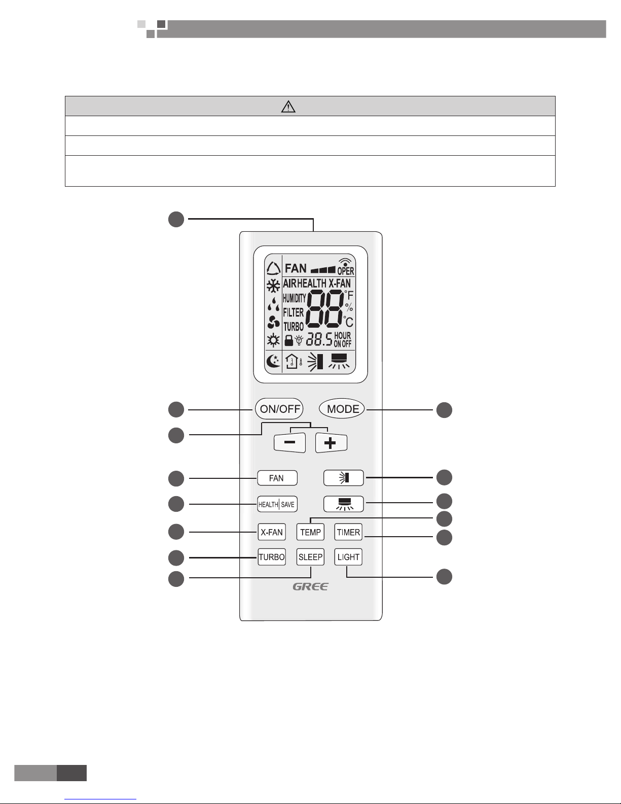
3.1.2 Control panel of the wireless remote controller
1
4
2
5
7
9
3
8
6
10
14
13
12
11
Page 13
11
Condensing Unit
Service Manual
CONTROL
No.
Name Function Description
1
Signal transmitter
● Signal transmitter
2
ON/OFF button
● Press this button, the unit will be started or stopped, which can clear the timer or sleeping
function of last time.
3
MODE button
● Press this button, the running mode will change as below:
AUTO ; COOL; DRY; FAN; HEAT (only for cooling and heating unit)
4
+/- button
● When press + button , the setting temp. will be increased by 1 oC ,When press - button,the
setting temp. will be decreased by 1 oC. The temp. will be changed quickly by pressing the
button continuously and setting temp. range is 16-30 oC
5
FAN button
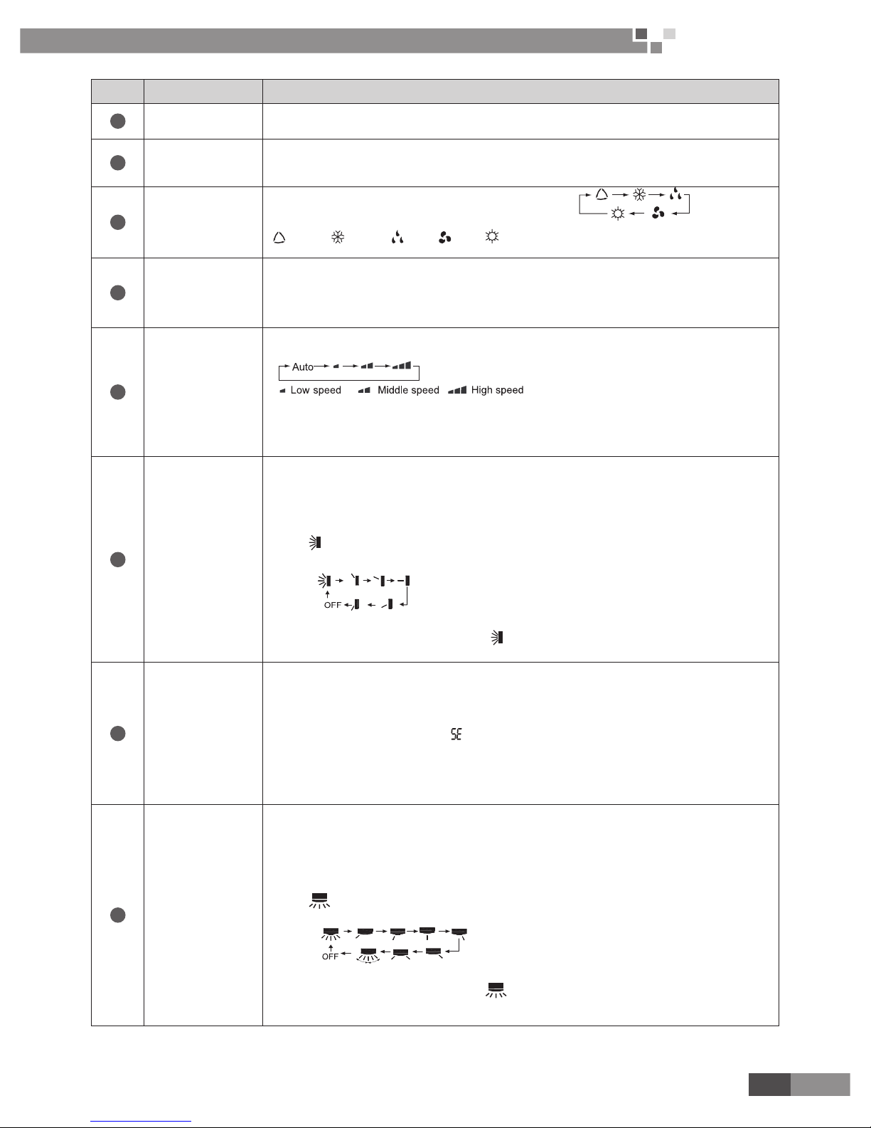
● Press this button once, fan speed will change as below:
Note: Under the DRY mode, the fan will be kept running at the low speed and the fan
speed isn't adjustable.
6
Swing up and
down button
● Simpleness swing mode is defaulted for wireless remote controller, in this mode, press
this button, could turn on or turn off the Up and down swing function.
● When unit is turned off, synchronously press "+" and Up and down swing buttons, it could
be switched between the simpleness swing mode and stationary swing mode, at this
time, blinks 2 seconds.
● In Stationary swing mode, press this button,the angle for Up and down swing as show in
below:
● When up and down swing louver is working,when turn off the unit, the siwng louver will
immediately stop at current position. shows up and down swing louver swings back
and forth as show in the above gure.
7
HEALTH |
SAVE button
● HEALTH function: press the left part of this button,can set up Health function on or off.
After unit is turned on ,Health function ON is defaulted.
● Save energy function: Under Cool mode ,press the right part of this button, the wireless
remote controller will display “ ”, the whole unit will enter into “Electricity Save mode”,
repress this button, the whole unit will quit this mode, other mode button is not available.
Under the Energy Save mode, the temperature and the Fan speed on the wireless
remote controller are not adjustable.
8
Left and right
swing button
● Simpleness swing mode is defaulted for wireless remote controller,in this mode,press this
button, could turn on or turn off the Left and right swing function.
● When unit is turned off, synchronously press "+" and Left and right swing buttons, it could
be switched between the simpleness swing mode and stationary swing mode, at this
time, blinks 2 seconds.
● In Stationary swing mode, press this button,the angle for Left and right swing as show in
below:
● When left and right swing louver is working, when turn off the unit, the siwing louver will
immediately stop at current position. shows left and right swing louver swings back
and forth as show in the above gure.
Page 14

12
Condensing Unit
Service Manual
CONTROL
9
X-FAN button
● Pressing X -FAN button in COOL or DRY mode, the icon "X-FAN" is displayed and the
indoor fan will continue operation for 10 minutes in order to dry the indoor unit even
though you have turned off the unit. After energization, X-FAN OFF is defaulted. X-FAN is
not available in AUTO,FAN and HEAT mode.
10
TEMP button
● After powered on, displaying presetting temperature is defaulted,(According to customer
requirements to display,if there are no requirements,the presetting temperature displaying
is defaulted, there is no signal display on the wireless remote controller). Press this
button, (display ), display the presetting temperature; (display ), display indoor
ambient temperature, will not change current display status. If current display status
is indoor ambient temp. when received other wireless remote controller sginal, then will
display presetting temp., 5s later return to ambient temp. display.
● Other models haven't this function. But pressing this button, the main unit will click and
keep the original status.
11
TIMER button
● On the status of the unit on, press this button to set timer off. On the status of the unit off,
press this button to set timer on. Press this button once, words Hour on(off) will appear
and icker. In which case, press +/- button to adjust time (press +/- button continuously
to change timing value quickly ), the setting time range is from 0.5 to 24 hr. ; press this
button once again to fix the time,then the wireless remote controller will send out the
signal immediately and hour on/off will stop ickering.If the time of that no press timer
button under ickering status is above 5s,the timer setting will quit. If the timer has been
set,press this button once again to quit it.
12
TURBO button
● Set turbo on or off(the characters of turbo will appear or disappear ) by pressing this
button under cooling or heating mode.Once energized, the unit will be defaulted to be
turbo off. This function can not be set under auto, dehumidify or fan mode, and characters
of turbo won't appear.
13
SLEEP button
● Press this button, enter into SLEEP state,when repressed, it will quit. The sleep function
will be canceled with the stop of the unit. There is no SLEEP function under AUTO and
FAN mode. is the icon for sleep function.
● At COOL, X-FAN mode: the SLEEP mode runs after 1hour, the setting temp. will be
increased by 1 oC, 2 hour later, the setting temp. will be increased by 2 oC and then will
run at this setting temperature.
● At HEAT mode: the SLEEP mode runs after 1 hour, the setting temp. will be decreased
by 1 oC, 2 hours later the setting temp. will be decreased by 2 oC, then it will run at setting
temperature.
14
LIGHT button
● Press this button to select LIGHT on or off in the displayer. When the LIGHT on is set,the
icon will be displayed and the indicator light in the displayer will be on. When the
LIGHT off is set, the icon will be not displayed and the indicator light in the displayer
will be off.
3.1.3 Introduction for special function
About X-FAN function
This function indicates that moisture on evaporator of indoor unit will be blowed after the unit is stopped to
avoid mould.
(1). Having set X-FAN function on: After turning off the unit by pressing ON/OFF button indoor fan will
continue running for about 10 min. at low speed. In this period, press X-FAN button to stop indoor fan
directly.
(2). Having set X-FAN function off: After turning off the unit by pressing ON/OFF button, the complete unit will
Page 15

13
Condensing Unit
Service Manual
CONTROL
be off directly.
About AUTO RUN
When AUTO RUN mode is selected, the setting temperature will not be displayed on the LCD, the unit will
be in accordance with the room temp. automatically to select the suitable running method and to make ambient
comfortable.
About turbo function
If start this function, the unit will run at super-high fan speed to cool or heat quickly so that the ambient
temp. approachs the preset temp. as soon as possible.
About lock
Press +and - buttons simultaneously to lock or unlock the keyboard. If the wireless remote controller is
locked, the icon will be displayed on it, in which case, press any button, the mark will icker for three times. If
the keyboard is unlocked, the mark will disappear.
About switch between Fahrenheit and Centigrade
Under status of unit off, press MODE and - buttons simultaneously to switch oC and oF.
About new function of defrosting
It indicates: after starting this function by wireless remote controller and the unit has been under defrost
status, If turn off the unit by wireless remote controller, the unit will not stop defrosting until it is finished; if
change setting mode by wireless remote controller, the function ,which is set last time, won't be carried out until
defrosting nished.
Operation of this function on or off: If wireless remote controller is under off status, press mode button and
X-FAN button simultaneously in order to enter or cancel this new function. If the unit is under defrost mode, dual
eight position on wireless remote controller will display H1.If switch to heat mode, the position will display H1,
which ickers for 5s, in which case, press +/- button, H1 will disappear and setting temp. be displayed.
After wireless remote controller is powered on , the new defrost function will be defaulted to be closed.
3.1.4 Replacement of batteries
1
Slightly press the place with along the arrowhead direction and push the back cover of the wireless
remote controller.
2
Take out the used batteries.
3
Insert two new AAA 1.5V dry cell batteries and pay attention to their polarity.
4
Put back the cover of the wireless remote controller.
2
3
4
1
Note:
When changing the batteries, do not use the old or different batteries, otherwise, it can cause the
malfunction of the wireless remote controller.
If the wireless remote controller will not be used for a long time, please take them out, and don't let the
leakage liquid damage the wireless remote controller.
It should be placed where is 1m away from the TV set or stereo sound sets.
The operation should be in its receiving range.
If the wireless remote controller cannot operate normally, please take the batteries out, and then reinsert it
30s later; if it is also abnormal ,please replace the batteries
If the main unit needs to be remote controlled, please aim wireless remote controller at the receiver of
main unit in order to improve the receiving sensitivity of the main unit.
Page 16

14
Condensing Unit
Service Manual
CONTROL
When the wireless remote controller sends out signal, a mark will icker for about 1s. The bell will ring if
the main unit receives effective signal.
3.2 Wired Controller (Chosen Accessory Part)
3.2.1 Display View
Fig.3.2.1 Outline of wired controller
3.2.2 Operation View
Fig.3.2.2 Instruction to Function of Buttons
No. Description Function of Button
1 Enter/cancel Function selection and canceling;
2 ▲
①
Running temperature setting of indoor unit, range :16~30°C.
②
Timer setting, range:0.5-24hr
③
Switchover between quiet/auto quiet
6 ▼
3 Fan Setting of high/middle/low/auto fan speed
4 Mode Setting of cooling/heating/fan/dry mode of indoor unit
5 Function Switch over among these functions of air/sleep/turbo/save/e-heater/blow /quiet
Page 17

15
Condensing Unit
Service Manual
CONTROL
7 Timer Timer setting
8 On/off Turn on/off indoor unit
4 Mode
and
2 ▲
Memory function
Press Mode and ▲for 5s under off state of the unit to enter/cancel key memory
function (If memory is set, indoor unit will resume original setting state after
power failure and then power recovery. If not, indoor unit is defaulted to be off
after power recovery. Memory function is defaulted to be set before outgoing.)
2 ▲
and
6 ▼
Lock
Upon startup of the unit without malfunction or under off state of the unit, press
▲ ▼ key at the same time for 5s in to lock state. In this case, any other buttons
won’t respond the press. Repress ▲ ▼ key for 5s to quit lock state.
5 Function
And 7Timer
Setting Ambient
Temperature Sensor
and three Grades of
Speed for Indoor Fan
Under off state of the unit, press Function and Timer buttons continuously for 5s
to go to the debugging menu. Press Mode button to adjust the setting items and
▲ or ▼ button to set the actual value.
4 Mode
and 6▼
Select Centigrade or
Fahrenheit
Under off state of the unit, press Mode and ▼ at the same time for 5s, the
displayer panel will switch between Centigrade and Fahrenheit.
5 Function
and 6▼
Enquiry of Historical
Errors
Continuously press Function and ▼ buttons for 5s to go to the enquiry state.
In this state, press Enter/Cancel button to quit, or it will automatically quit after
there is not any operation of button in 30min
3.2.3 Display View
Fig.3.2.3 LCD display
Table 3.2.3
No. Description Instruction to Displaying Contents
1 Swing Swing function
2 Air
*
Air exchange function
3 Sleep Sleeping states
4 Running mode Each kind of running mode of indoor unit (auto mode)
5 Cooling Cooling mode
Page 18

16
Condensing Unit
Service Manual
CONTROL
6 Dry Dry mode
7 Fan Fan mode
8 Heating Heating mode
9 Defrost Defrosting state
10
Gate-control
card
*
Gate control
11 Lock Lock state
12 Shield
Shielding state (buttons, temperature, on/off, mode or save is shielded by long-distance
monitoring
13 Turbo Turbo function state
14 Memory
Memory state (Indoor unit resumes original setting state after power failure and then
power recovery)
15 Twinkle Flicking when unit is on without operation of buttons
16 Save Energy-saving state
17 Temperature Ambient/setting temperature value
18 E-Heater
*
Mark that E-heater is allowed to turned on
19 Blow Blow mark
20 Timer Timer-displayed location
21 Quiet Quiet state(two types: quiet and auto quiet)
Notes: The functions with * are reserved for other models and are not applicable for the models listed in this manual.
3.2.4
Dimension
Fig.3.2.4
Page 19

17
Condensing Unit
Service Manual
CONTROL
3.2.5 Installation
Fig.3.2.5 Sketch for Installation of Wired Controller
No. 1 2 3 4 5
Description
Socket’s base
box installed in
the wall
Soleplate of
controller
Screw M4×25
Front panel of
controller
Screw ST 2.9×6
(1). Cut off power supply of heavy-current wire embedded in mounting hole in the wall before installation. It is
prohibited to perform the whole procedure with electricity.
(2). Pull out 4-core twisted pair line in mounting hole and then make it through the rectangle hole at the back
of controller’s soleplate.
(3). Joint the controller’s soleplate on wall face and then x it in mounting hole with screws M4×25.
(4). Insert the 4-core twisted pair line through rectangle hole into controller’s slot and buckle the front panel
and soleplate of controller together.
(5). At last, x the controller’s front panel and soleplate with screws ST 2.9×6.
Caution:
During connection of wirings, pay special attention to the following items to avoid interference of
electromagnetism to unit and even failure of it.
①.
To ensure normal communication of the unit, signal line and wiring (communication) of wired controller
should be separate from power cord and indoor/outdoor connection lines. The distance between them
should be kept 20cm in min.
②.
If the unit is installed at the place where there is interference of electromagnetism, signal line and wiring
(communication) of wired controller must be shielded by twisted pair lines.
Page 20

18
Condensing Unit
Service Manual
INSTALLATION
Page 21

19
Condensing Unit
Service Manual
INSTALLATION
1 INDOOR UNIT INSTALLATION
1.1 Installation of Ceiling Type
1.1.1 Before Installation
When the unit arrives, please check if any damage due to transport is existent. If any hurt is found on the
surface or inside, please declare to the transport company or the manufacturer in writing.
When the unit arrives, please check if any damage due to transport is existent. If any hurt is found on the
surface or inside, please declare to the transport company or the manufacturer in writing.
Correct handling route and method shall be decided to prevent damage to the unit. For protecting the unit
and ensuring its safety, carrying the unit with its package is recommended. If such carrying method is
difcult under particular conditions, the canton shall not be removed to avoid looseness or falling during
handling.
Confirm the foundation is secure. When the unit is installed on the metal part of a building, electrical
insulation must be in compliance with relevant standards.
Conrm the installation position is away from storage zone of inammable and explosive substances, or
otherwise leakage of inammable and explosive substances may lead to explosion or a re.
1.1.2 Installation Site
Such a place where cool air can be distributed throughout the room.
Such a place where condensation water is easily drained out.
Such a place that can handle the weight of indoor unit.
Such a place which has easy access for maintenance.
Such a place where is permitting easy connection with the outdoor unit.
Such a place where is 1m or more away from other electric appliances such as television, audio device,
etc.
Avoid a location where there is heat source, high humidity or inammable gas.
Do not use the unit in the immediate surroundings of a laundry, a bath, a shower or a swimming pool.
Be sure that the installation conforms to the installation dimension diagram.
The space around the unit is adequate for ventilation
1.1.3 Caution for Installation
Adjust the distance from the unit to the ceiling slab beforehand (Refer to Figure 1-2-1).
Fix the hanger bracket to the suspension bolt (Refer to Figure 1-2-2).
Make sure that extended suspension bolt from the ceiling stays inside the arrowed position. Readjust the
hanger bracket when it is outside the arrowed position. (Refer to Figure 1-2-3)
Suspension bolt stays inside the cap of indoor unit .Never remove the cap. Lift the unit and slide forward
unit the dent. (Refer to Figure 1-2-4)
Screw tightly both hanger bracket setting bolts (M8) (Refer to Figure 1-2-2)
Screw tightly both hanger bracket xing bolts (M6) to prevent the movement of the indoor unit. (Refer to
Figure 1-2-2)
Adjust the height by turning the nut with a spanner. Insert the spanner from the hanger bracket opening.
(Refer to Figure 1-2-5)
40mm or less
Suspension bolt
Ceiling
Hanger bracket
Hanger bracket
setting bolt(M8)
Hanger bracket
foxing bolt(M6)
Hanger bracket Figure 1-2-1 Figure 1-2-2
Page 22

20
Condensing Unit
Service Manual
Figure 1-2-3 Hanger bracket Figure 1-2-4
In case of hanging:
It is possible to install using inward facing hanger bracket by not removing the brackets from the indoor unit.
(Refer to Figure 1-2-6) Be sure to use only the specied accessories and parts for installation work.
Figure 1-2-5 Figure 1-2-6
1.1.4 Dimension Data
Figure 1-2-7
Page 23

21
Condensing Unit
Service Manual
Table 6
Unit: mm
Model A B C D H
HNTF24/A-D
1220 225 1158 280 700
HNTF36/A-D
HNTF48/A-D
1420 245 1354 280 700
HNTF60/A-D
1.1.5 Installation Clearance Data
100cm or m ore
30cm or m ore
60cm or m ore
60cm or m ore
150cm or m ore
Figure 1-2-8
1.1.6 Drain Piping Work
(1). Installation of Drainage Pipeline
A Drainage outlet is located at both the left and right sides of the indoor unit. After selecting one Drainage
outlet, the other outlet shall be blocked by rubber plug. Bundle the blocked outlet with string to avoid
leakage, and also use thermal insulation materials to wrap the blocked outlet.
When shipped out from factory, both the Drainage outlets are blocked by rubber plugs.
When connecting the drainage pipe with the unit, do not apply excessive force to the pipeline at the side of
the unit. The xing position of the pipeline shall be near the unit.
Purchase general-purpose hard PVC pipe locally to be used as the drainage pipeline. When carrying
out connection, place the end of the PVC pipeline into the drainage hole. Use exible drainage tube and
tighten it with thread loop. Never use adhesive to connect the drainage hole and the exible drainage tube.
(As shown in Figure 1-2-9)
When the laid drainage pipe is used for multiple units, the common pipe shall be about 100mm lower than
the drainage outlet of each set of unit. A pipe with thicker wall shall be used for such purpose.
Sponge (gray)
Drain hose
Clamp
Clamp(attachment)
Sponge(attachment)
Below 4mm
Figure 1-2-9
Page 24

22
Condensing Unit
Service Manual
(2). Testing of Drainage System
After the electrical installation is completed, carry out the testing of the drainage system.
During the test, check if the water correctly flows through the pipelines. Carefully observe the joints to
ensure that there is no leakage. If the unit is to be installed in a new house, carry out testing before
decorating the ceiling.
(3). Matters of Attention
The drain pipe outlet direction can be chosen from either the right rear or right.
The diameter of the drain pipe should be equal to or greater than the diameter of the connecting pipe.
(Vinyl tube; pipe size: 20mm; outer dimension: 26mm)
Keep the drain pipe short and incline downwards at a gradient of at least 1/100 to prevent air pockets.
(Refer to Figure 1-2-10) .
When drain hose is connected
Incline the drain hose
Not to be lifted
Not foldings
Not to be soaking in water
Figure 1-2-10
No folding of drain hose inside the indoor unit. (Refer to Figure 1-2-11)
Conrm that smooth drainage is achieved after the piping work. Pour 600 cc of water into the drain pan
from the air outlet for conrming drainage. (Refer to Figure 1-2-12).
Wartering can Air outlet
Figure 1-2-11 Figure 1-2-12
3 REFRIGERATION PIPING WORK
3.1 Refrigeration Piping Work Procedures
(1). Connecting pipelines
Connection pipes must be in accordance with the following requirements: the basic principle --- keeping
dry, clean and no leakage inside.
Page 25

23
Condensing Unit
Service Manual
Dry Clean Air tight
Make syre there is no
moisture inside the pipes
Make sure there is no
dirt inside the pipe
Make sure the refrigerant
does not leak out
Moisture
(V0965)
Dirt
(V1148)
Leak
(V1149)
Figure 3-1-1
Align copper pipe are with the center of screwed connector and tighten fully the nut of the are by hand.
Tighten the are nut with a torque spanner until the torque spanner makes a click, as shown in Figure 3-1-
1. Moment needed for tightening a nut is shown in Tab. 3-1-1.
Fitting Pipe for Indoor Unit Flaring Nuts Fitting pipe
Torque Spanner
Spanner
Figure 3-1-2
Form 3-1-1 the tightening torque needed for tightening nut
Pipe diameter Tightening torque
1/4" 15-30 (N·m)
3/8" 35-40 (N·m)
5/8" 60-65 (N·m)
1/2" 45-50 (N·m)
3/4" 1-75 (N·m)
7/8" 85-90 (N·m)
Curvature of piping shall not be too small, or otherwise piping may be broken. So installation personnel
should use a pipe bender to bend pipes.
Upward or longitudinal welding joint method is usually applied to the welding of pipelines. The welding
method that mouth of pipe is downward (face-down welding) should be avoided as far as possible,
because such method is prone to welding defects and even would cause leakage, as shown in Figure 3-1-
3.
Page 26

24
Condensing Unit
Service Manual
Bume
r
Solder
Downward facing
Side facing
Recommended methed
Upward facing
Figure 3-1-3
Uninsulated connecting pipes and connectors should be packed with sponge and tied with plastic adhesive
tapes.
(2). Vacuum-pumping and leak detection
Dismantle the bonnet of refrigerant valve and air valve.
Align with the center of piping and adequately tighten nuts of connecting pipes by hand
Tighten the nuts with a spanner.
Remove the one way valve cap of air valve.
Unscrew the spool of refrigerant valve for 1/4 turn with a socket head wrench, and at the same time push
up the spool of air valve with a screwdriver to let air give off.
Air exhaust continues for 15 seconds until coolant gas appears, immediately shut off one way valve and
tighten the valve cap.
Totally open the spool of refrigerant valve and air value (as shown in Figure 3-1-4)
One-Way Valve
Gas Valve
Liquid Valve
Valve Cap
Inner Hexagon
Spanner
Screwdriver
Valve Stem
Figure 3-1-4
Tighten the valve caps and use soapy water or a leak detector to check any leakage on indoor unit,
outdoor unit and connection parts of pipes.
Caution:
If conditions are allowed, a vacuum pump shall be used for drawing off air inside the system at a valve. Method
for creation of vacuum by using a vacuum pump is as follows:
Take out the nut cover of the inlet for refrigerant.
Connect the tube of the vacuum watch with the vacuum pump, having the low-pressure end linking to the
inlet for refrigerant. (As shown in Figure 3-1-5)
Page 27

25
Condensing Unit
Service Manual
Pressure Gage Pressure Gage
“LO” Knob
“HI” Knob
Liquid Valve Vacuum Pump
Connecting Hose
Gas Valve
Figure 3-1-5
Starting the vacuum pump, when the indicator turns to-1 bar, closing the low pressure handle and stopping
vacuumize. Keep for 15 minutes, ensuring the pressure of the vacuum watch remains.
Take out the valve cover of the gas valve together with the liquid valve.
Loosing the cord of liquid valve until the pressure rise to 0 bar.
Dismantle the tube from the cover of the inlet for refrigerant then, tighten the cover.
Loose the valve cord of the gas valve as well as the liquid valve entirely.
Tighten the valve cover of the gas valve and liquid valve so as to check whether leakage occurred.
(3). Installation of Protective Layer of Connecting Pipe
To avoid generation of condensate on the connecting pipe and avoid leakage, the big pipe and the small
pipe of the connecting pipe must be covered by thermal insulation materials, be bundled by adhesive tape,
and be isolated from air.
The joint connecting to the indoor unit must be wrapped by thermal insulation material. There shall be no
gap between the connecting pipe joint and the wall of the indoor unit. Refer to Figure 3-1-6.
Figure 3-1-6 Figure 3-1-7
Use adhesive tape to bundle the connecting pipe and the cables together. To prevent condensate from
overflowing out from the drainage pipe, separate the drainage pipe firm the connecting pipe and the
cables.
Use thermal insulation tape to wrap the pipes from the bottom of the outdoor unit until the upper end of the
pipe where the pipe enters the wall. When wrapping thermal insulation tape, the later circle of tape must
cover half of the front circle of tape (Figure 3-1-7).
Wrapped pipe must be xed to wall using pipe clamps.
Caution:
After the pipes are wrapped by protective materials, never bend the pipes to form very small angle, and
Page 28

26
Condensing Unit
Service Manual
otherwise the pipes may crack or break.
Do not wrap the protective tape too tight, otherwise the efciency of thermal insulation may be decreased.
Ensure that the condensate drainage exible tube is separate from the bundled pipes.
After the protective work is completed and the pipes are wrapped, use seal material to block the hole in the
wall, so as to prevent rain and wind from entering the room.
3.2 Caution in Connecting Pipes
Arrangement of connecting pipes shall be performed according to sit conditions with reference to the
following principles.
Try to shorten the length of connecting pipes, within 5m for the better.
Try to reduce height difference between indoor unit and outdoor unit.
Try to reduce number of joint bends of connecting pipes.
If the length of connecting pipes is more than 20m, adequacy of lubricant of the system must be checked;
and if necessary, add more lubricant properly.
Filling amount of refrigerant in the system is matched to a 7m connecting pipe. If the connecting pipe is
needed to lengthen, appropriate amount of refrigerant should be added. How much refrigerant should be
added for every meter extension refers to the following table. Allowable maximum pipe length is 30m.
If height difference between indoor unit and outdoor unit exceeds 10m in installation of air conditioner, an
oil return bend must be mounted at an interval of 6m.
If heights of indoor unit and outdoor unit are different, pipes should be laid out with reference to Figure 3-2-
1.
3.3 Specication of Connection Pipe
Mode
External Diameter
Maximum Length
of Connection Pipe
Maximum Difference
in Height between
Outdoor and Indoor Unit
Additional Charge
of Refrigerant
Gas Pipe Liquid Pipe (m) (m) (m)
HNTF24/A-D 3/8 5/8 15 15 0.6
HNTF36/A-D 3/8 3/4 30 15 0.6
HNTF48/A-D 3/8 7/8 30 15 0.6
HNTF60/A-D 1/2 7/8 30 15 1.2
4 ELECTRIC WIRING WORK
4.1 Wiring Principle
4.1.1General
Perform wiring of the power supply in conformance with the regulations of the local electric company.
For the control wires connecting indoor units, and between indoor and outdoor units, use of double-core
shield wires is recommended to prevent noise trouble.
Be sure to set the earth leakage breaker and the switches to the power supply section of the indoor unit.
Supply power to each outdoor unit and provide an earth leakage breaker or hand switch for each outdoor
unit.
Store wiring system for control and refrigerant piping system in the same line.
Arrange the cables so that the electric wires do not come to contact with high-temperature part of the
refrigerant pipe; otherwise coating melts and an accident may be caused.
Do not turn on power of the indoor unit until vacuuming of the refrigerant pipe will nish.
Installation should be conducted by National Wiring Regulation.
The rated voltage and exclusive power supply must be adopted for the air conditioners.
The power cable should be reliable and xed, in order to avoid the wiring terminal be suffered from force.
And do not drag the power cable forcibly.
The wire diameter of power cable should be large enough, if power cable and connection wire be
Page 29

27
Condensing Unit
Service Manual
damaged, it should be replaced by the exclusive cable.
All electric installation must be done by professional personnel according to local law, regulation and this
manual.
It should be reliably earthed, and it should be connected to the special earth device, the installation work
should be operated by the professional.
The creepage protect switch and air switch must be installed.
Air switch should have the thermal dropout and magnetic dropout function, in order to avoid the short
circuit and overload.
The on spot connection should refer to the circuit diagram, which is stuck on the unit body.
The unit should be reliably earth, if it is improperly earthed that may cause electric shock or re.
Air conditioner is the “I” class electric appliance, thus please do conduct reliable grounding measure.
The yellow-green two-color wiring of air conditioner is grounding wire and cannot be used for other
purposes. It cannot be cut off and be xed by screw, otherwise it would cause electric shock.
The user must offer the reliable grounding terminal. Please don’t connect the grounding wire to the
following places:
a. Water pipe;
b. Gas pipe;
c. Blowing pipe;
d. Other places that professional personnel consider them unreliable;
4.1.2 Connection of electric wires with the terminal
(1). Caution
Before installing the electrical equipment, please pay attention to the following matters which have been
specially pointed out by our designers:
Check to see if the power supply used conforms to the rated power supply specied on the nameplate.
The capacity of the power supply must be large enough. The section area of tting line in the room shall be
larger than 2.5mm2.
The lines must be installed by professional personnel.
An electricity leakage protection switch and an air switch with gap between electrode heads larger than 3
mm shall be installed in the xed line.
(2). Connection of single wire
Use wire stripper to strip the insulation layer (25mm long) from the end of the single wire.
Remove the screw at the terminal board of the air-conditioning unit.
User pliers to bend the end of the single wire so that a loop matching the screw size is formed.
Put the screw through the loop of the single wire and x the loop at the terminal board.
(3). Connection of multiple twisted wires
Use wire stripper to strip the insulation layer (10mm long) from the end of the multiple twisted wires.
Remove the screw at the terminal board of the air-conditioning unit.
Use crimping pliers to connect a terminal (matching the size of the screw) at the end of the multiple twisted
wires.
Put the screw through the terminal of the multiple twisted wires and x the terminal at the terminal board.
25
10
A. Singel wireB . Multiple twisted wires
Terminal
Insulation layer
Page 30

28
Condensing Unit
Service Manual
Warning:
If the power supply exible line or the signal line of the equipment is damaged, only use special exible line
to replace it.
Before connecting lines, read the voltages of the relevant parts on the nameplate. Then carry out line
connection according to the schematic diagram.
The air-conditioning unit shall have special power supply line which shall be equipped with electricity
leakage switch and air switch, so as to deal with overload conditions.
The air-conditioning unit must have grounding to avoid hazard owing to insulation failure.
All tting lines must use crimp terminals or single wire. If multiple twisted wires are connected to terminal
board, arc may arise.
All line connections must conform to the schematic diagram of lines. Wrong connection may cause
abnormal operation or damage of the air-conditioning unit.
Do not let any cable contact the refrigerant pipe, the compressor and moving parts such as fan.
Do not change the internal line connections inside the air-conditioning unit. The manufacturer shall not be
liable for any loss or abnormal operation arising from wrong line connections.
4.2 WIRING DIADRAM
(1). Model: HNTF24/A-D, HNTF36/A-D, HNTF48/A-D, HNTF60/A-D
Page 31

29
Condensing Unit
Service Manual
4.3 Electric Wiring Design
Model: HW24Na/A-D + HNTF24/A-D, HW36Na/A-D + HNTF36/A-D;
Indoor Unit
POWER
220/230V
1PH
60HZ
POWER
220/230V
1PH
60HZ
Outdoor Unit
Model:HW48Na/A-D+HNTF48/A-D; HW60Na/A-D+ HNTF60/A-D;
POWER
220/230V
1PH
60HZ
POWER
220/230V
1PH
60HZ
Indoor Unit
Outdoor Unit
Page 32

30
Condensing Unit
Service Manual
MAINTENANCE
Page 33

31
Condensing Unit
Service Manual
MAINTENANCE
1TROUBLE TABLE(Only for oor ceiling)
Fault code Fault Fault code Fault
E2
Indoor Frost-
Proof Protection
F0
Failure of Indoor Room
Sensor at Air Intake
E6 Communications Failure F1 Failure of Evaporator Temp. Sensor
EH
Failure of Auxiliary
Heater
F5
Failure of Indoor Room
Sensor at Wire Controller
2 FLOW CHART OF TROUBLESHOOTING
2.1 Air ow volume from air outlet of unit is abnormal
Yes
Yes
Yes
Yes
No
No Yes
No Yes
Yes
No
Air flow volume from
air outlet of unit is
abnomal
Filter in air return
box isn’t blocked
Re-connect
power cord
Capacitor in centrifugal
fan’s return circuit is
burnt out
Replace capacitor
centrifugal fan
normally runs
centrifugal fan motor
has malfunction
Repair or replace
motor
Power cord of centrifugal
fan is in good contact
and not broken
Power of centrifugal
fan is on
Clean fifiter
Page 34

32
Condensing Unit
Service Manual
2.2 The unit can not start up for cooling
The unit can not start
up for coolin g
Power supply is normal,
fuse is not burned out and
circuit does not break
Power switc h is switche d
on and in good contact
Resume power suppl y,repl ace
fuse or re-connect circuit
Yes
Yes
No
No
Conn ection of power
cord of unit is correct
No
Yes
Electrical elements in
electric box are
undamaged
Repair or replace power switch
to swi tch on pow er supply
Re -conn ect powe r cord
Replace damag ed elements
Yes
No
Page 35

33
Condensing Unit
Service Manual
2.3 Poor cooling effect
Poor cooling effect
Yes
Eliminate affected factors or
re-select installation location of unit
No
No
No
Clear sundries
Clean filter
No
Repair or replace motor
Compressor runs
Yes
Axial flow fan runs
Installa tion location
of unit co nforms to requir ements or th ere
isn’t an y factor around the unit wh ich
affects heat di spersion of unit
Yes
Yes
Yes
No
Repair or replace
compressor
Condenser isn’t
blocked by sundries
Filter in air return
box is not blocked
Repair or replace motorCentrifugal fan runs
Yes
No
Yes
Pipeline system is
normal in respect of low/high
pressure detection
Shortage of refrigerant
or nozzle for adding
freon leaks refrigeran
Piping system,capillary
or strainer is blocked
No
Clean or replace
it after disassembly
Replace
Yes
Yes
Page 36

34
Condensing Unit
Service Manual
2.4 Noise or abnormal vibration of unit
The unit can not start
up for cooling
Yes
Re-install unit or eliminate
affected factors
No
No
No
Adjust tightness of compressor
Tighten loose part
Repair or replace motor
No
Repair or replace compressor
Fan motor runs
Yes
Compressor runs
Installation of unit or pedestal meet requirements
Fixation of compressor’s
holding bolt is all right, and there is no strenuous
vibration of compressor
Fixation of fan bracket
is all righ t, moto r is tight ened, and th ere is no strenuou s
vibration of fan
Yes
Yes
Yes
No
Page 37

35
Condensing Unit
Service Manual
4 DISASSEMBLY AND ASSEMBLY PROCEDURE OF MAIN PARTS
Model:
HNTF24/A-D, HNTF36/A-D, HNTF48/A-D, HNTF60/A-D
Disassembly of panel grating module
Remark: Make sure that the power supply is cut off before disassembling and protect all the parts during disassembly. Do not put lter
screen near the high temperature heat source.
Step Illustration Handling Instruction
Disassembly of sub-assy of
front grill
●Unscrew the 2 clasps of the upper grill and the
2 screws of the clasps.
●Open the grill, disassemble the 2 down clasps
to remove the grill.
Disassembly of right and left nishing plates
Remark: Make sure the power supply is cut off before disassembling and protect all the parts during disassembly. Do not scratch the outer
parts.
Step Illustration Handling Instruction
Disassembly of right and left
nishing plates
●Disassemble the screws as shown in the
graph with screwdriver and then push upward
to remove the right and left nishing plates.(As
is shown in the graph, arrow represents the
position of screws.)
Disassembly of panel parts
Remark: Make sure the power supply is cut off before disassembling and protect all the parts during disassembly. Do not scratch the outer
parts.
Step Illustration Handling Instruction
Disassembly of panel parts
●Unscrew the 3 sides’ screws on the cover to
remove the cover.
Disassembly of sub-assy of electric box
Remark: Make sure that the power supply is cut off before disassembling and protect all the parts during disassembly, especially the
components inside the box in case of water and hit.
Step Illustration Handling Instruction
Disassembly of electric box
cover
●Disassemble 3 screws as shown by the arrow
in the graph on left and remove the electric box
cover.
Disassembly of air deecting plate modules
Remark: Make sure the power supply is cut off before disassembling and protect all the parts during disassembly, especially the joints of
the air deecting plate.
Step Illustration Handling Instruction
Disassembly of sub-assy of
air deecting plate
●Remove the air deflecting plates from the air
deflecting plate support assembly, and then
remove both ends from the air sweeping
motor. joint (As is shown in the graph, arrow
represents the support assembly and circle the
air sweeping motor joint.)
Page 38

36
Condensing Unit
Service Manual
Disassemble of water-containing plate modules
Remark: Make sure the power supply is cut off before disassembling and protect all the parts during disassembly.
Step Illustration
Handling Instruction
Disassemble of water-
containing plate modules
●Remove the water-containing plate modules.
Disassembly of evaporator components
Remark: Make sure that the power supply is cut off and protect the copper tube and aluminum n. If the time for disassembly shall be long,
seal the copper tube .
Step Illustration Handling Instruction
Disassembly of evaporator
components
●Unscrew the 6 screws of evaporator, 3 screws
of water groove press board and the 2 screws
of water board to remove the evaporator.
Disassembly of xing plate sub-assy for air sweeping fans
Remark: Make sure that the power supply is cut off before disassembling and protect all the parts during disassembly.
Step Illustration Handling Instruction
Disassembly of xing plate
sub-assy for air sweeping
fans
●Remove the display board, mounting support
and mounting plate of swing motor in turn.
Disassembly of fan and motor components
Remark: Make sure that the power supply is cut off before disassembling and protect all the parts during disassembly, especially the
fastening screws for fans.
Step Illustration Handling Instruction
1. Disassembly of front and
back scroll cases
●Press the buckle at the joints of front and back
scroll cases with hands and pull upward to
remove the front scroll case. Then remove the
screws on the back scroll case. Lift the buckle
of back scroll case with hands and remove
it.(As is shown in the graph, circle represents 2
screws on left and right.)
2. Disassembly of fans
●Unscrew the 2 screws of coupling, take out
the rotating shaft and louver, then loosen the
tighten screw of louver to remove the louver
3. Disassembly of bearing
xing plates
●Unscrew the 3 screws and 2 nuts of support to
remove the mounting support.
Page 39

37
Condensing Unit
Service Manual
4. Disassembly of motor
●Loosen the 2 screws of the motor attaching
clamp, remove the motor attaching clamp and
motor attaching clamp subassembly to remove
the motor.
Disassembly of right and left xing plates
Remark: Make sure that the power supply is cut off before disassembling and protect all the parts during disassembly.
Step Illustration Handling Instruction
Disassembly of right and left
xing plates
●Disassemble the bolts on right and left fixing
plates with tools. (As is shown by the arrow in
the graph.)
Page 40

38
Condensing Unit
Service Manual
5 EXPLODED VIEWS AND PART LIST
(1). Model: HNTF24/A-D, HNTF36/A-D
Exploded Views
Page 41

39
Condensing Unit
Service Manual
HNTF24/A-D, HNTF36/A-D Spare Parts List
NO Description Product Code Qty
1 Top Cover Board Sub-Assy '01269409 1
2 Water Tray Assy '01289404 1
3 Filter Sub-Assy '07210028 1
4 Connected Board (Evaporator) '01349421 1
5 Evaporator Assy '01022200017 1
6 Temperature Sensor '3900020723 1
7 Room Sensor '39000191 1
8 Remote Controller '305100611 1
9 Right Cover Plate '26909444 1
10 Connection Board '02229406 1
11 Axile Bush '10542704 2
12 Right Side Plate Sub-Assy '01319429 1
13
Plate Board of Water
Releasing Flume
'26909442 1
14 Water Releasing Flume '02284106P 1
15
Guide Louver Supporting
Sub-Assy
'0180941601 1
16 Air Louver '10619404 16
17 Guide Louver '10619403 2
18 Rotating Shaft '26909430 4
19 Front Connection Board '01349414P 1
20 Membrane '63079403 1
21 Fixed Mount '26909426R 1
22 Display Board '30294220 1
23 Rear Side Plate Assy '01319400008 1
24 Rotating Shaft '26909413 1
25 Rotating Shaft '26909412 1
26 Stepping Motor '1521240206 1
27 Left Side Plate Sub-Assy '01319428 1
28 Electric Box Assy '01392200049 1
29 Transformer '4311023701 1
30 Transformer '43110286 1
31 Main Board '30224220 1
32 Electric Box Cover '01429420 1
33 Terminal Board '4201019601 1
34 Terminal Board '42011147 1
35 Terminal Board '42010194 1
36 Left Cover Plate '26909443 1
37 Capacitor '33010025 1
38 Mid-clapboard sub-Assy '01249416 1
39 Support Of Motor Bearing '01792408 2
Page 42

40
Condensing Unit
Service Manual
40 O-Gasket of Bearing '76512404 2
41 Centrifugal Fan '10425200 4
42 Front Volute Casing '26905205 4
43 Rear Connection board '01349422 1
44 Bar Clasp Sub-Assy '70818000001 1
45 Fan Motor '15709409 1
46 Joint Slack '73018731 2
47 Drainage Pipe Sub-Assy '05235434 1
48 Rear Volute Casing '26905206 4
49 Filter Sub-Assy '11729402 1
50 Front Grill Sub-Assy '01579403 2
Note: Above data is subject to change without notice, pls reference the SP in global service website.
Page 43

41
Condensing Unit
Service Manual
(2). Model: HNTF48/A-D, HNTF60/A-D
Exploded Views
HNTF48/A-D, HNTF60/A-D Spare Parts List
NO Description Product Code Qty
1 Top Cover '01269404P 1
2 Water Tray Assy '01289405 1
3 Air Louver '26909418 18
4 Connected Board (Evaporator) '01349413 1
5 Filter Sub-Assy '07210029 1
6 T h r o t t l e V a l v e S u b - a s s y '07332200032 1
7 Evaporator Assy '01022200026 1
8 Room Sensor '39000191 1
9 Tube sensor '3900020720G 1
10 Remote Controller '305100611 1
11 Right Side Plate Sub-Assy '01319408 1
12 Right Cover Plate '26909422 1
Page 44

42
Condensing Unit
Service Manual
13 Connection Board '02229406 1
14 Right Foam Assy '12509425 1
15 Axile Bush '10542704 2
16
Plate Board of Water
Releasing Flume
'26909442 1
17 Water Releasing Flume '26909441 1
18 Rotating Shaft '26909413 1
19 Guide Louver '26909432 2
20 Front Connection Board '01349408P 1
21
Front Connection
Board Foam Assy
'12509424 1
22 Membrane '63079403 1
23 Fixed Mount '26909426R 1
24 Display Board '30294220 1
25 Rear Side Plate Assy '01319400005 1
26 Stepping Motor '1521240206 1
27 Left Foam Assy '12509408 1
28 Electric Box Assy '01392200054 1
29 Transformer '4311023701 1
30 Transformer '43110286 1
31 Main Board '30224220 1
32 Terminal Board '4201019601 1
33 Terminal Board '42011147 1
34 Terminal Board '42010194 1
35 Capacitor CBB61 '33010014 1
36 Electric Box Cover '01429410P 1
37 Left Cover Plate '26909416 1
38 Mid-Clapboard Sub-Assy '01249412 1
39 Bracket 1 01809404 1
40 Support Of Motor Bearing '01792408 1
41 O-Gasket of Bearing '76512404 1
42 Centrifugal Fan '1041410101 3
43 Rear Volute Casing '26909419 3
44 Joint Slack '73018731 1
45 Fan Motor '15709407 1
46 Front Volute Casing '26905208 3
47 Back Connection Board '01349418 1
48 Drainage Pipe Sub-Assy '05235434 1
49 Rotating Shaft '26909430 6
50 Rotating Shaft '26909412 1
51 Front Grill Sub-Assy '01579402 3
Note: Above data is subject to change without notice, pls reference the SP in global service website.
Page 45

JF00302341
 Loading...