

Gree HLR35SM/NaA-M, HLR45SM/NaA-M Service Manual

Modular Mini Chiller Service Manual
(T1/R410A/50Hz)
GREE ELECTRIC APPLIANCES INC. OF ZHUHAI

GREE COMMERCIAL AIR CONDITIONERS MODULAR MINI CHILLER
2
CONTENTS
PRODUCT INTRODUCTION.......................................................................................................................4
1 MODELS LIST .........................................................................................................................................4
1.1 Integral Type ....................................................................................................................................4
2 NOMENCLATURE ..................................................................................................................................4
2.1 Integral Type ....................................................................................................................................4
3 FUNCTION...............................................................................................................................................4
4 PRODUCT DATA.....................................................................................................................................5
4.1 Product Data at Rated Condition..................................................................................................5
4.2 Operation Range.............................................................................................................................6
4.3 Electrical Data .................................................................................................................................6
5 PIPING DIAGRAM..................................................................................................................................6
UNITS CONTROL .........................................................................................................................................8
1 OPERATION FLOWCHART....................................................................................................................8
1.1 Cooling Operation...........................................................................................................................8
1.2 Heating Operation...........................................................................................................................9
2 MAIN LOGIC .........................................................................................................................................10
2.1 Cooling Mode ................................................................................................................................10
2.2 Heating Mode ................................................................................................................................10
2.3 Anti-freezing Running ...................................................................................................................11
2.4 Control of Compressor.................................................................................................................11
2.5 Control of Four-way Valve ...........................................................................................................11
2.6 Control of Water Pump.................................................................................................................11
3 WIRED REMOTE CONTROLLER........................................................................................................ 12
3.1 Function..........................................................................................................................................12
3.2 Operation View..............................................................................................................................12
3.3 Display View ..................................................................................................................................13
3.4 Wired Controller Operation Instructions ....................................................................................13
3.5 Controller Menu Structure............................................................................................................26
4. SKETCH MAP OF DIP SWITCH ..........................................................................................................27
UNITS INSTALLATION ..............................................................................................................................29
1 UNITS INSTALL....................................................................................................................................29
1.1 Installation Positions.....................................................................................................................29
1.2 Matters need Attention.................................................................................................................29
1.3 Dimension Data.............................................................................................................................29
1.4 Installation Clearance Data .........................................................................................................30
2 WATER PIPING WORK.........................................................................................................................31
2.1 Installation Procedure...................................................................................................................31
2.2 Matters of Attention.......................................................................................................................31
2.3 Antifreeze .......................................................................................................................................31
3 ELECTRIC WIRING WORK..................................................................................................................31
3.1 Wiring Principle .............................................................................................................................31
3.2 Electrical Wires are Connected with Consumers.....................................................................32
3.3 Specification of Power Cord & Air Switch..................................................................................32
3.4 Wiring Diagram..............................................................................................................................33
UNITS MAINTENANCE..............................................................................................................................35
1 TROUBLE TABLE .................................................................................................................................35
2 FLOW CHART OF TROUBLESHOOTING...........................................................................................37
3 DISASSEMBLY AND ASSEMBLY PROCEDURE OF MAIN PARTS.................................................41
3.1 Integral Type ..................................................................................................................................41
4 EXPLODED VIEW AND PARTS LIST..................................................................................................43
4.1 Exploded View and Parts List- Integral Type............................................................................43

MODULAR MINI CHILLER PRODUCT
3
PRODUCT
MODULAR MINI CHILLER PRODUCT
4
PRODUCT INTRODUCTION
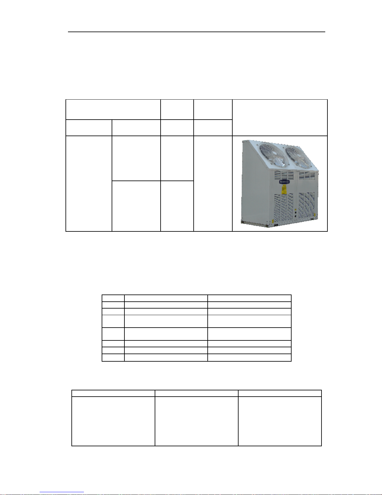
1 MODELS LIST
1.1 Integral Type
Model
Nominal
Capacity
Power
Supply
Refrigerant Model Name kW (V,Ph,Hz)
Appearance
HLR35SM/NaA-M 35
R410A
HLR45SM/NaA-M 45
380∼415V,
3Ph, 50Hz
Note:1Ton =12000Btu/h = 3.517kW
2 NOMENCLATURE
2.1 Integral Type
HL R 35 S
M
Na - M
1 2 3 4
5
6 7
NO. Description Options
1 Mini chiller 2 Product type R=Heat pump
3 Nominal Cooling Capacity
35=35kW
45=45kW
4 Refrigeration Circuits
Default=One circuit
S=Twin circuit
5 Module 6 Refrigerant Na=R410A, Default=R22
7 Voltage
M=380∼415V 3Ph 50Hz
3 FUNCTION
Indoor Unit Type Function Description
Integral Type
Heating/Cooling
Interface kit for up to 16 indoor
units
Memory restart
Two circuits optimized design
Low noise design
Safety and reliability thanks to
advance compressor balance
control
MODULAR MINI CHILLER PRODUCT
5
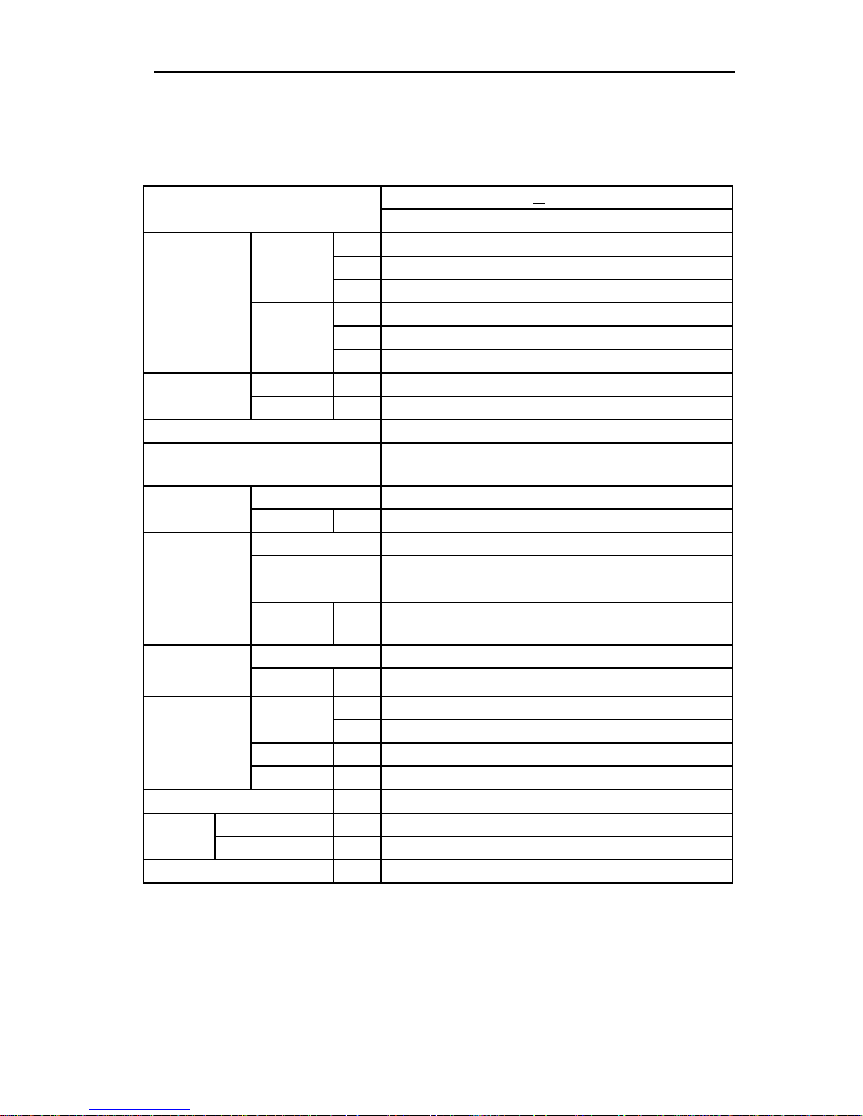
4 PRODUCT DATA
4.1 Product Data at Rated Condition
4.1.1 Integral Type
HLR SM/NaA-M
Models
35 45
kW 31 42
Btu/h 105772 143303
Cooling
RT 8.8 11.9
kW 36 49
Btu/h 122832 167187
Capacity
Heating
RT 10.3 13.9
Cooling kW 11.9 18.3
Power input
Heating kW 12.5 17.5
Power Supply 380~415V,3Ph,50Hz
Safeties Auto air evacuation valve
Safety valve;
Auto water replenishing valve;
Auto air evacuation valve
Type R410A
Refrigerant
Charge kg 6.5X2 7.3X2
Type scroll
Compressor
NO. 2 2
Heat Exchanger Shell and tube Shell heat exchanger
Evaporator
Water In/Out
Pipe
Diameter
inch 1-1/2”
Heat Exchanger Aluminum fin-copper tube Fin sleeve Heat exchanger
Condenser
Fan Motor
Power Input
kW 0.6 0.8
L/s \ 2.2
Water Flow
GPM \ 29
Delivery Lift m \ 27
Pump
Power Input kW \ 1.5
Expansion Vessel Volume L \ 8
Outline(WxDxH) mm 1750×800×1760 1750×800×1760
Dimension
Packaged(WxDxH) mm 1910×960×1970 1910×960×1970
Net/Gross Weights
kg
600/610 755/765
NOTE:
1、Cooling capacity is based on the following conditions:leaving chilled water temp.7 ,outdoor air temp.35℃℃
2、Heating capacity is based on the following conditions:leaving warmed water temp.45 , outdoor air ℃
temp.7℃
3、Water flow range for operation must be from 70% to 120% of the rated water flow。
4、The maximum allowable pressure for water pipe is 0.9MPa
MODULAR MINI CHILLER PRODUCT
6
4.2 Operation Range
Mode
Range of Outdoor Temperature℃ (℉)
Cooling 16~48
Heating -15~28
4.3 Electrical Data
4.3.1 Integral Type
Compressor Fan Motor Total
Model
Rated Power
Supply
NO.
LRA
each
(A)
MRC
each
(A)
NO.
MRC
(A)
MRC
(A)
NRC
(A)
HLR35SM/NaA-M
380~415V 3Ph
50Hz
2 101 17.3 2 1 36.6 26.3
Notes:
LRA: Locked rotor amps (A)
MRC: Maximum running current (A)
NRC: Nominal running current (A)
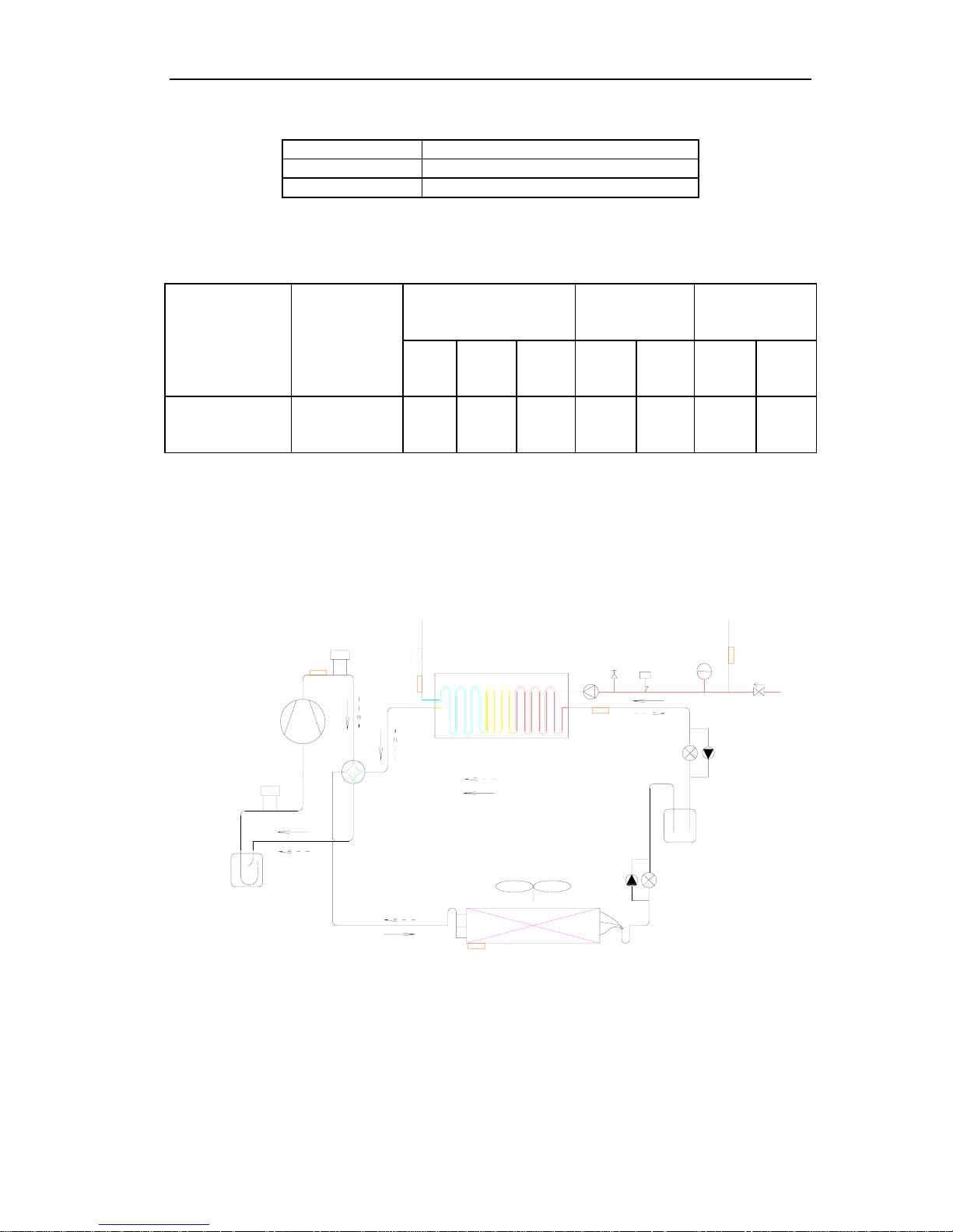
5 PIPING DIAGRAM
Heating circuit
Cooling circuit
Pump
Relief
valve
Flow
switch
Expansion
drum
High pressure
tank
Aluminum fin-copper tube
coil
Four-way valve
Shell and tube heat
exchanger
Inlet
Outlet
High-pressure
switch
Compressor
Low-pressure
switch
Liquid-gas separator
F

GREE COMMERCIAL AIR CONDITIONERS MODULAR MINI CHILLER
7
CONTROL
MODULAR MINI CHILLER CONTROL
8
UNITS CONTROL
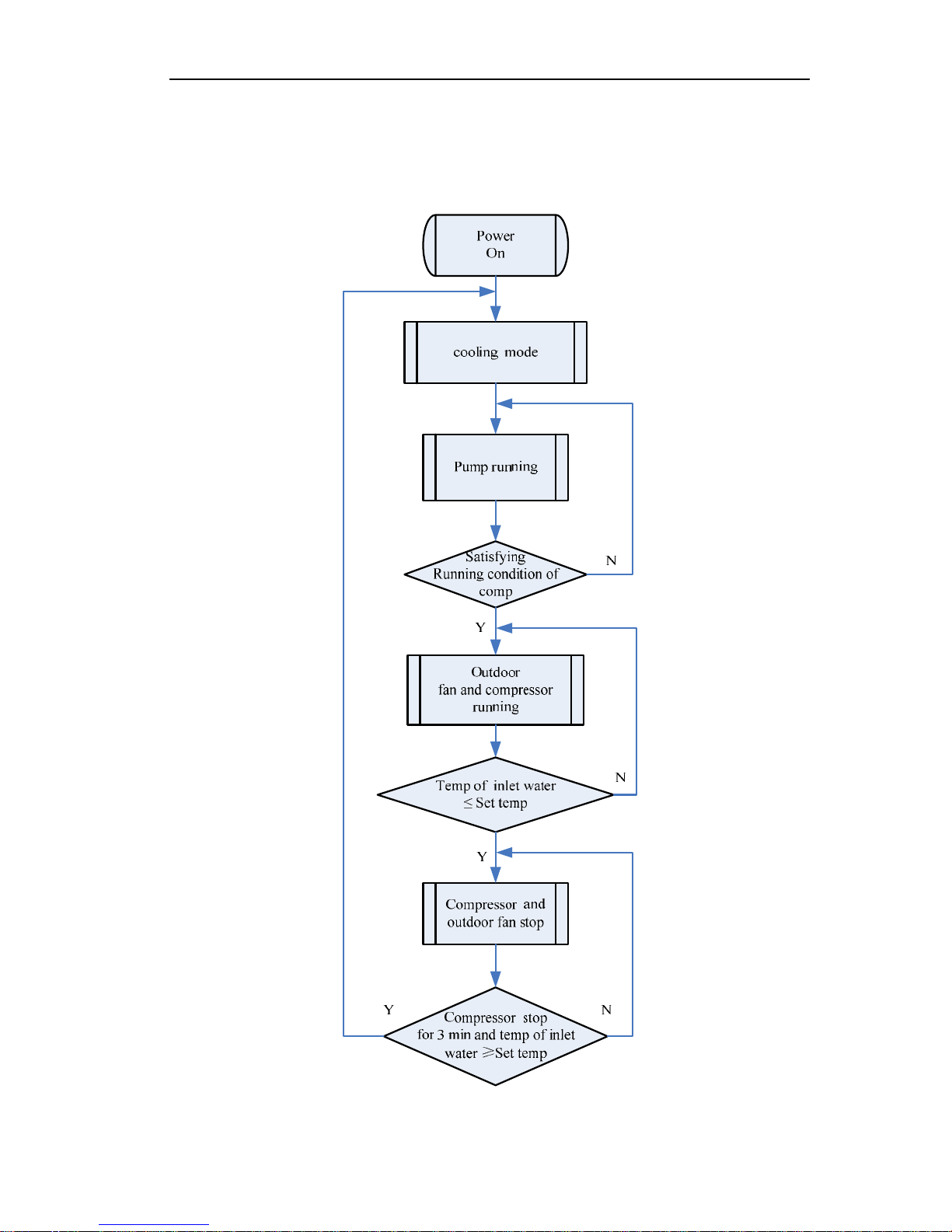
1 OPERATION FLOWCHART
1.1 Cooling Operation
MODULAR MINI CHILLER CONTROL
9
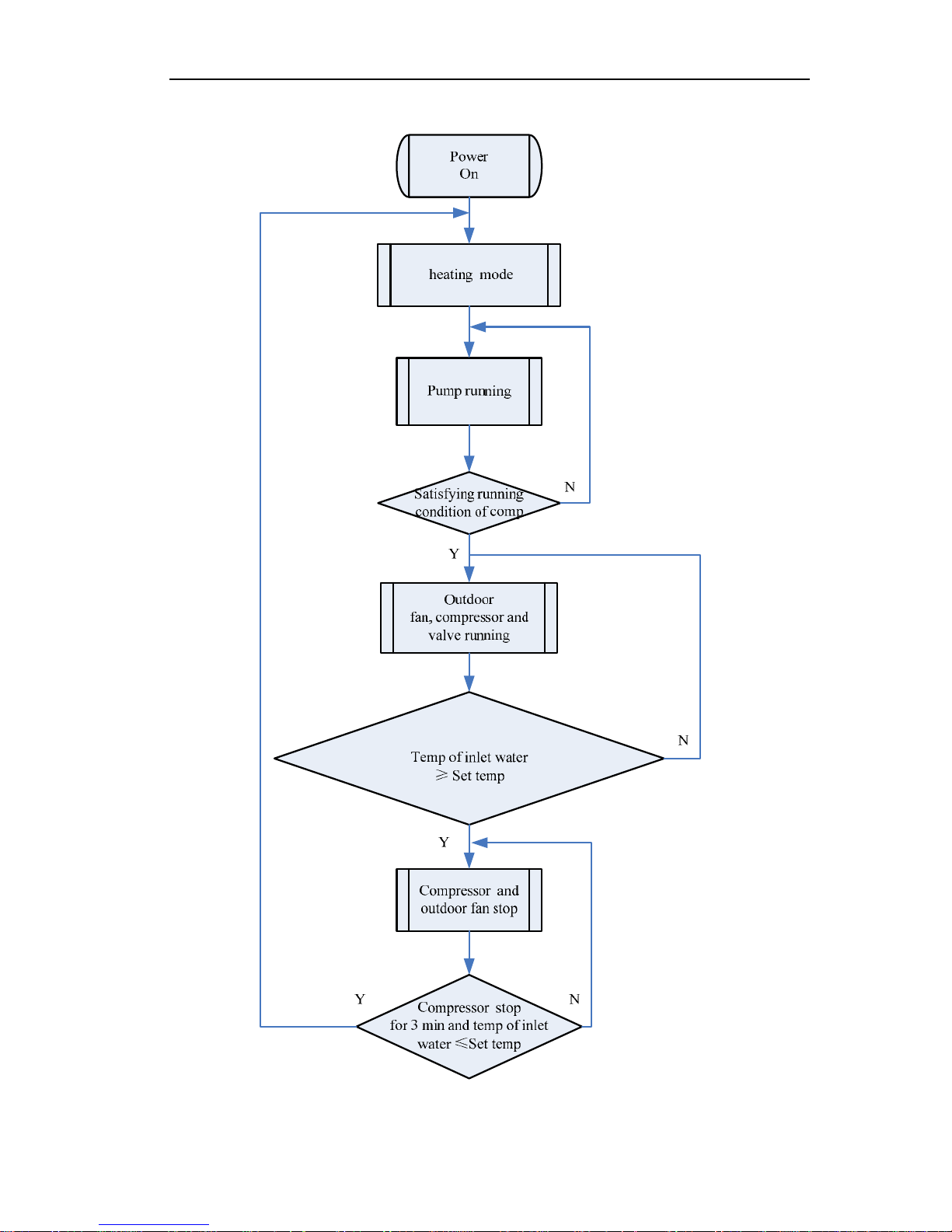
1.2 Heating Operation

MODULAR MINI CHILLER CONTROL
10
2 MAIN LOGIC
2.1 Cooling Mode
2.1.1 Control of Compressor
(1)Start-stop Control--- “first start, first stop; first stop, first start”
During running of the unit, the compressor is numbered instantly. It is controlled according
to the principle of “first start, first stop; first stop, first start”.
(2)Water Temperature Drop (Rise) Rate Control
The water temperature interval is the main control, while the temperature drop (rise) rate is
the auxiliary control. This can adapt to the load variation of the terminal, keeping water
temperature stable and avoiding fierce variation. In this control mode, the system is based on
the temperature and temperature drop rate: when the water temperature is too high and if the
temperature drop is rapid, it means the output load is bigger than the terminal load. In that
case, it is not necessary to startup the other compressor. The temperature interval and
temperature drop is decided by experience, other theories and test so that the water
temperature can be kept stable and frequent stop can be avoided.
2.1.2 Anti-freezing Protection
For each module, when the anti-freezing temperature is lower than the required value for
protection, the anti-freezing protection will start then the compressor of this module will stop.
When the anti-freezing temperature is higher than the required value for resume, this system
will eliminate the anti-freezing protection.
When the anti-freezing temperature is between the above two temperature, it will not affect
the anti-freezing protection.
If the unit is low temperature unit, the anti-freezing protection is invalid.
2.1.3 Stop of the Unit
Stop the unit manually or via timer: the compressor stops and then the fan stops. After
certain control time, the water pump will stop.
Stop the unit upon reaching a temperature spots: the compressor stops and then the fan
stops (on condition that both compressor stops). The water pump will not stop.
Disorderly closedown: the compressor stops and then the fan stops (except the
malfunction of the fan). After the corresponding compressor stops for a period. The water
pump will not stop.
2.2 Heating Mode
2.2.1 Control of Compressor
The control principle is the same with that of cooling mode.
2.2.2 Superheat Protection
For each module, when the superheat temperature is higher than the required value for
protection, the superheat protection will start then the compressor of this module will stop.
When the superheat temperature is lower than the required value for resume, this system will
eliminate the superheat protection.
When the superheat temperature is between the above two temperature, it will not affect
the superheat protection.
2.2.3 Control of Auxiliary E-heater

MODULAR MINI CHILLER CONTROL
11
If the control function of auxiliary e-heater is switched on in the display board, it can be
controlled automatically according to the inflow water temperature. It is necessary to set an
interval to restart the e-heater.
When the temperature detected by inflow water temperature sensor is ≤T1, the second
group of auxiliary e-heaters will work.
When the inflow water temperature is ≥T2, the second group of auxiliary e-heaters will
stop.
When the inflow water temperature is between the above two temperature, the second
group of auxiliary e-heaters remain the original state.
When the temperature detected by inflow water temperature sensor is ≤T1+tr0, the first
group of auxiliary e-heaters will work.
When the inflow water temperature is ≥T2+tr1, the first group of auxiliary e-heaters will
stop.
When the inflow water temperature is between the above two temperature, the first group
of auxiliary e-heaters remain the original state.
After startup of the unit, the auxiliary e-heater will work after all the compressor runs for a
certain period and all the above condition is reached.
2.2.4 Stop of the Unit (subject to the stop of the compressor)
Stop the unit manually or via timer: the compressor, the auxiliary e-heater and the fan
stops in sequence. After certain setting time, the four-way valve will be de-energized and the
water pump will stop.
Stop the unit upon reaching the temperature spots: the compressor stops and then the fan
stops. The four-way valve will remain the original state and the water pump will not stop.
Disorderly closedown: the compressor stops and then the fan stops (unless the fan is
wrong). After the corresponding compressor stops for a period. The water pump will not stop
while the four-way valve will remain the original state.
2.3 Anti-freezing Running
Under the stop state of any mode (except manual defrosting mode), the automatic
anti-freezing function can be switched on via the display board. The defaulted setting of this
function is OFF.
For all the modules that reach automatic anti-freezing running condition, the compressor
will run according to the setting condition and the regulation of “run for 6min and stop for 4
min”.
2.4 Control of Compressor
All compressors run according to the principle of “first start, first stop; first stop, first start”.
For other information, refer to the control section of 1.3.1 and1.3.2.
2.5 Control of Four-way Valve
In cooling mode, the four-way valve is off. In heating mode, the four-way valve will run after
the corresponding compressor runs. In defrosting mode, the four-way valve will be off. When
eliminating the defrosting function, the four-way valve runs. When stop the unit, the four-way
valve will stop after the corresponding compressor stops.
2.6 Control of Water Pump
When any of the modules needs to be started up, all the water pumps will run. When one
module stops upon reaching certain temperature spots, all the water pumps remain running.
When one module is stopped manually or via timer or due to malfunction, the water pump of
this module remains running. Only when all the modules are stopped manually or via timer, the
water pump will stop 5 min after all the compressor stops.
MODULAR MINI CHILLER CONTROL
12
3 WIRED REMOTE CONTROLLER
3.1 Function
The display of modular air-cooled scroll chiller shows the running parameter in real time. It can
be connected with the remote control system.
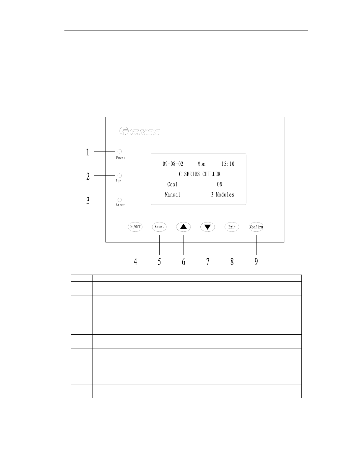
3.2 Operation View
NO. Name Function description
1 Power LED (red)
When the display board is energized, this LED lights;
otherwise, it is dark.
2 Running LED (green)
When the display board is turned on, this LED lights; otherwise,
it is dark.
3 Error LED (red) When there is malfunction, this LED lights; otherwise it is dark.
4 ON/OFF button
Control the start or stop of the unit. Under stop state, press the
button (for 3s) to start up the unit. Under running state, press
the button (for 3s) to stop the unit.
5 RESTORE button
Press this button to remove error and lock of exhaust
temperature sensor.
6 UP button
Press this button to move the cursor upward or leftward. When
modify the data, press this button to increase the value.
7 DOWN button
Press this button to move the cursor downward or rightward.
When modify the data, press this button to decrease the value.
8 EXIT button Press this button to return to last page.
9 CONFIRM button
Press this button to enter the next page. When modify the data,
press this button to confirm the value and transfer the cursor.
MODULAR MINI CHILLER CONTROL
13
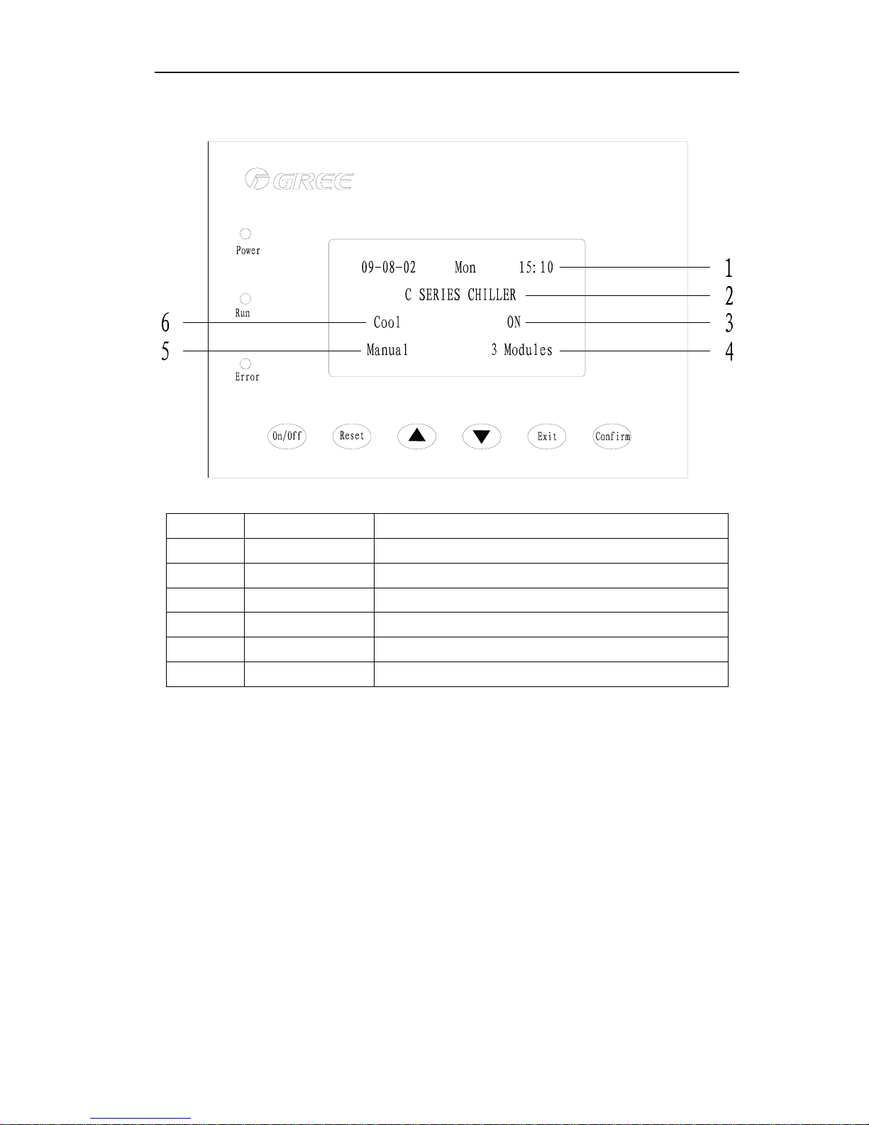
3.3 Display View
NO. Name Function description
1 Time display Display the current time.
2 Unit name Unit name
3 Running state Display the current running state of the unit.
4 Number of modules The number of connected unit
5 ON/OFF mode ON/OFF mode of the system
6 Running mode Display the current running mode
3.4 Wired Controller Operation Instructions
3.4.1 Turning on/off of the Unit
The unit under non-commissioning state can be turned on/off via the manual mode or the
timing mode. The manual mode is given priority to the timing mode.
●Manual mode:
1)、Manual start: in the unit stop state, press the on/off button for 3 seconds and start the
unit, and at that time the operation indicator is on. When the compressor begins to run
after a delay, the manual starting process is finished.
2)、Manual stop: in the unit operation state, press the on/off button for 3 seconds and
stop the unit, and at that time the operation indicator is off. When the unit stops, the
compressor immediately ceases and the cooling tower fan, the cooling pump and the
chilled water pump are shut off. The manual stop process is finished.
When ambient temperature is lower than -16℃, pressing the start/stop button, the
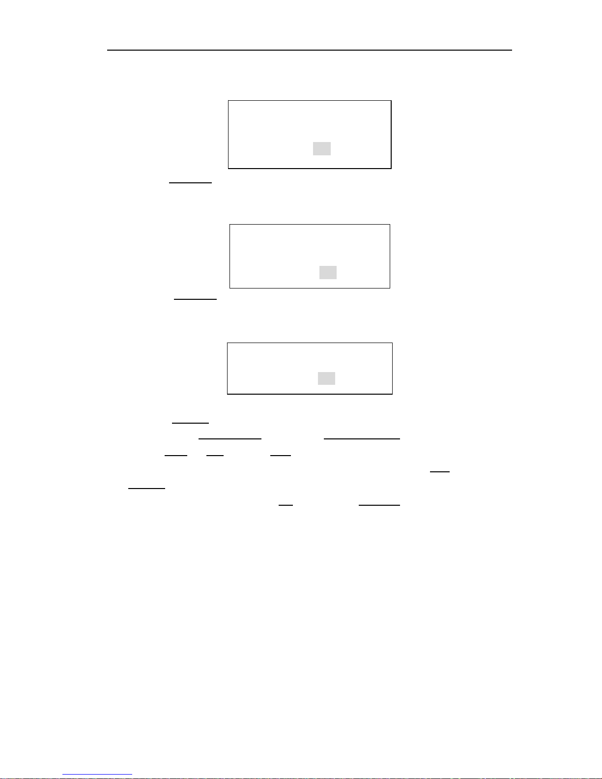
MODULAR MINI CHILLER CONTROL
14
following prompt window comes up on the manual operator.
Press the Confirm
button for acknowledgement.
If ambient temperature sensors of all linked units are at fault, pressing the on/off button,
the following prompt window comes up on the manual operator.
Press the Confirm
button for acknowledgement.
In the manual defrosting mode, pressing the on/off button, the following prompt
window comes up on the manual operator.
Press the Confirm
button for acknowledgement.
By pressing the up selection
button or the down selection button, you can convert
between YES
and NO. Press the Exit to quit selection and go back to home page. When
the unit is in the cooling & heat recovery mode stop state, if you select YES
and press the
Confirm
, you can go back to the home page and the unit is in the heating & heat recovery
operation state; and if you select NO
and press the Confirm, you can go back to the
home page and the unit is in the cooling & heat recovery operation state.
●Timing mode:
After the unit is energized or reset, press the Manual Mode to turn on/off the unit.
Conversion between the manual mode and the timing mode is detailed in 3.4.2.2 Main
Menu
3.4.2 Menu Operation Instructions
3.4.2.1 Home page
When the controller is powered on, the microcomputer will make a 3-second
automatic detection and the LCD on the wired controller will display the following content.
Don’t ON/OFF under
manual defrost!
OK
No ON/OFF
Under low ambient
Temp.
OK
No ON/OFF under
all ambient temp.
sensor fail!
OK
 Loading...