

Gree HL8WZ-K, HR8WZ-K, HL10WSZ-K, HR10WSZ-K, HL12.5WSZ-K Installation And Operation Manual
...Page 1

Installation and Operation Manual
Z Series Combination Household (Townhouse) Central Air Conditioning Unit
GREE ELECTRIC APPLIANCES, INC. OF ZHUHAI
Please read this manual carefully before using this product and keep it properly for future reference.
Page 2
User Notice
Dear Users:
Thank you for choosing our Household (Townhouse) Central Air Conditioning Unit. Please
read this manual carefully before installation, and perform installation and usage by following
process instructed in this manual, so that you can comprehensively know and correctly use this
unit.
Specially remind you the meaning of following label:
Warning! Means incorrect operation may cause injuries and deaths or badly hurt.
Notice! Means incorrect operation may cause injuries or property loss.
Warning!
When using this unit in winter, if outer ambient temp. is lower than 0℃, the temperature at
where indoor unit is installed should approach to outdoor ambient temperature; Or if there are
no people in the room for a long time, indoor temperature should approach to outdoor ambient
temperature:
1) Adding antifreeze in water system. Refer the actual outdoor ambient temperature for add
proportion.
2) To cooling only unit, when it is not used in winter, drain out water in the unit and pipe to
present pipe heat exchanger, pipeline and water pump from breaking; if it is not sure whether water
in pipeline is drained clearly, do add antifreeze into the system pipeline.
3) Don’t cut off power when unit is off, or auto antifreeze operation protection will be
ineffective.
Warning!
1) Please have the unit installed by authorized service center. Improper installation may cause
water leakage, electric shock and re etc.
2) Don’t use or store ammable and explosive hazardousness near the unit.
3) Please turn off power of the unit immediately when malfunction (such as burning odor is
smelled) occurs.
4) Don’t insert nger or things into air outlet or air-in grille.
5) Don’t turn on or turn off the unit by plug or unplug power cord.
6) Don’t ret the unit. Please contact with dealer or professional installation personnel when
the unit needs to repair or move.
7) This product must not be disposed together with the domestic waste.This product has to be
disposed at an anthorized place for recycling of electrical and eletronic appliances.
Notice!
1) Before installation, please check if the adopted power is the same with that listed on
nameplate, and check the safety of power.
2) Before using, please check and conrm if wires and water pipes are connected correctly to
avoid water leakage, electric shock or re etc.
Page 3

3) There must be earth wire at power socket to prevent electric shock. Don’t connect earth
wire with gas pipe, water pipe, lightning rod or connection wire of telephone.
4) Don’t operate the unit with wet hand, and don’t allow children to operate the unit.
5) The On/off in Owner’s Manual means operation to on and off button of PCB for users; cut
off power means to stop supplying power to the unit.
6) Don’t directly expose the unit under the corrosive ambient with water or dampness.
7) Do conduct electric leakage detect after installation.
8) Operation conditions: Ambient outdoor temperature for heat pump operation must be from
-20 to 24℃; At the same time, Ambient outdoor temperature range for cooling operation must be
from 16 ℃to 43℃Furthermore, water temperature must be under 50℃.In order to avoid freezing
the double tube heater exchanger, water temperature must be beyond 5℃.
9) To be in compliance EN 61000-3-11,the product shall be connected only to a supply of
the system impedance:|Zsys|=0.391 ohms or less.Before connect the product to public power
network, please consult your local power supply authority to ensure the power network meet above
requirement.
Please contact with local dealer, authorized service center or ofce for any problem, or it is
also available to contact with our company directly.
Page 4

Contents
1. System Instruction ...................................................................................... 1
2. Product Features .......................................................................................... 1
3. Unit Introduction .......................................................................................... 2
3.1 Outline Sketch ....................................................................................... 2
3.2 Outline Sketch of Unit ........................................................................... 2
4. Operation Instruction to Control ................................................................. 4
4.1 Display function on display panel .......................................................... 4
4.2 LCD displaying panel ........................................................................... 4
4.3 Button function on display board .......................................................... 5
4.4 Buzzer ................................................................................................... 5
4.5 Basic operation ..................................................................................... 5
4.6 Error Code List ..................................................................................... 7
5. Daily Operation and Maintenance .............................................................. 8
6. Common Malfunction and Solution ............................................................ 8
7. Terminal Facilities and Selection Guideline ............................................. 10
8. System Installation .................................................................................... 10
8.1 Unit Installation ................................................................................... 10
8.2 Installation of terminal facilities ......................................................... 12
8.3 Water Pipe Connection ....................................................................... 13
8.4 Anti-freezing Notices .......................................................................... 14
9. System Adjustment ................................................................................... 15
9.1 Charge of Refrigerated Water to Air Conditioning System ................. 15
9.2 Check before Trial Run ....................................................................... 15
9.3 Trial Run .............................................................................................. 15
10. Usage Instruction for Accessories ........................................................... 16
10.1 Auto water ll valve .......................................................................... 16
10.2 Safety valve ...................................................................................... 17
10.3 Auto exhaust valve ............................................................................ 17
Page 5

Z series combination household (townhouse)central air conditioning unit
1
1. System Instruction
Combination Household (Townhouse) Central Air Conditioning Unit is a kind of small central air
conditioning unit that is mainly applied in the increasing high-grade ats, combination buildings, high-grade
villa, and unitary ofce, restaurants, department stores, entertaining places and other places that have special
air conditioning requirements.
Working principle of Combination Household (Townhouse) Central Air Conditioning Unit: Firstly, the
unit products cools (or heat) water, after being pressed by water pump, this cooled (heated) water will be
transferred to each indoor fan coil by water pipe (or other terminal facilities), and then through fan coil to
conduct heat exchange with indoor air circle make indoor air temperature lower (or higher), for the purpose
of air conditioning adjustment. Meanwhile, fresh air unit can be installed in the system to introduce certain
quantity of fresh air into rooms after ltering or lowering (or heating up) temperature so that indoor air can
still remain fresh and comfortable.
There are 3 parts that mainly combines into Combination Household (Townhouse) Central Air
Conditioning System.
①
Household (Townhouse) Central Air Conditioning Unit which divides into of
cooling only and heat pump. Outdoor units are usually placed at outdoor balcony, roof or special at roof;
indoor units can be placed in washing room or other indoor places. Outdoor and indoor units can also be
piled up together in outdoors. ② Terminal facility: Mainly indicates fan coil. Horizontal concealed fan coil is
usually recommended to simplify indoor tment. ③Water system: For connecting host and terminal fan coil
to transfer cool and heat. It is commonly made of galvanized pipe or seamless steel pipe. It can also adopt new
types of pipes such as PVC pipe, PPR pipe, or aluminum-plastic pipe etc.
2. Product Features
1) Humanized design, i.e. both split installation and integral installation are available.
2) Ultra-thin indoor unit design whose height is only 288mm to make hoisting easy.
3) Adopting casing heat exchanger to enhance unit performance, antifreeze ability and reliability.
4) System realized trinity
A set of heat pump system can both cool and heat, it saves gas system, and also collocate with household
replace, water boiler or city heating net. Thus, cooling, heating, and water heating become trinity.
5) Large range of cool water and heat water supply
When cooling, supply range for cool water is 7
℃~15℃
; when heating, supply range for heat water is
35
℃~50℃
.
6) High reliability
Heat transfer media of this unit is water and with no distance limitation, only considering enough water
pump lift can realize long-distance heating and cooling.
7) Control function in subrooms
It is available to conduct on or off control to host in rooms, that is, when order of turning on from only
a single room, host on; when all rooms send unit off order, host off; general control spot can be set at living
room to conduct prior control to unit.
8) Easy operation
Adopting advanced total computer control system, main control system can conduct complete control to
the unit. Since it is very easy and quick to reset the operation, it can satisfy users’ requirements. With multi-
point control function, it is available to control on/off of host from several rooms, i.e. when order of unit on
from only a single room, host on; when all rooms send unit off order, host off; general control spot can be set
at living room to conduct prior control to unit.
9) Easy dialogue interface
Host displays in English, and every operation data can be nd. When malfunction occur, unit will displays
error informational automatically, thus, repair and maintenance is very easy.
Page 6
Z series combination household (townhouse)central air conditioning unit
2
3. Unit Introduction
3.1 Outline Sketch
At low temperature, in order to counterbalance heat quantity which attenuates with the decline of outdoor
temperature auxiliary electric heater is recommended. This part is optional, users can choose according to
following table after consulting professionals.
HL(R)8WZ-K HL(R)10WSZ-K HL(R)12.5WSZ-K HL(R)15WSZ-K
2 kW 3 kW 5 kW 7 kW
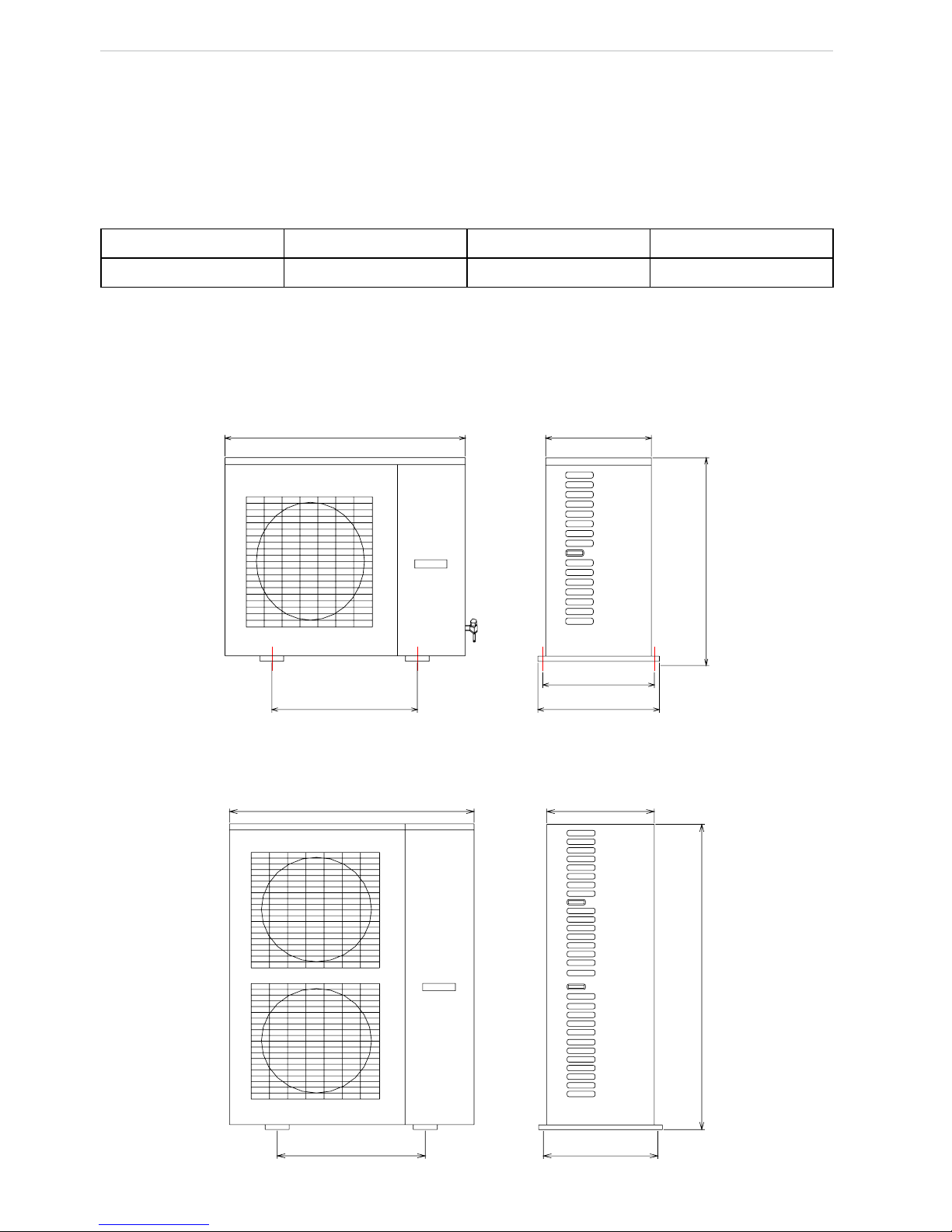
3.2 Outline Sketch of Unit
3.2.1 Outline Dimension of Outdoor Unit
Outline dimension diagram of HLR8WZNa-M(O)
Unit: mm
950
572
412
378
340
840
Outline dimension diagram of HLR10WZNa-M(O) 、HLR12.5WZNa-M(O) 、 HLR15WZNa-M(O)
Unit: mm
950
572
340
1250
370
Page 7
Z series combination household (townhouse)central air conditioning unit
3
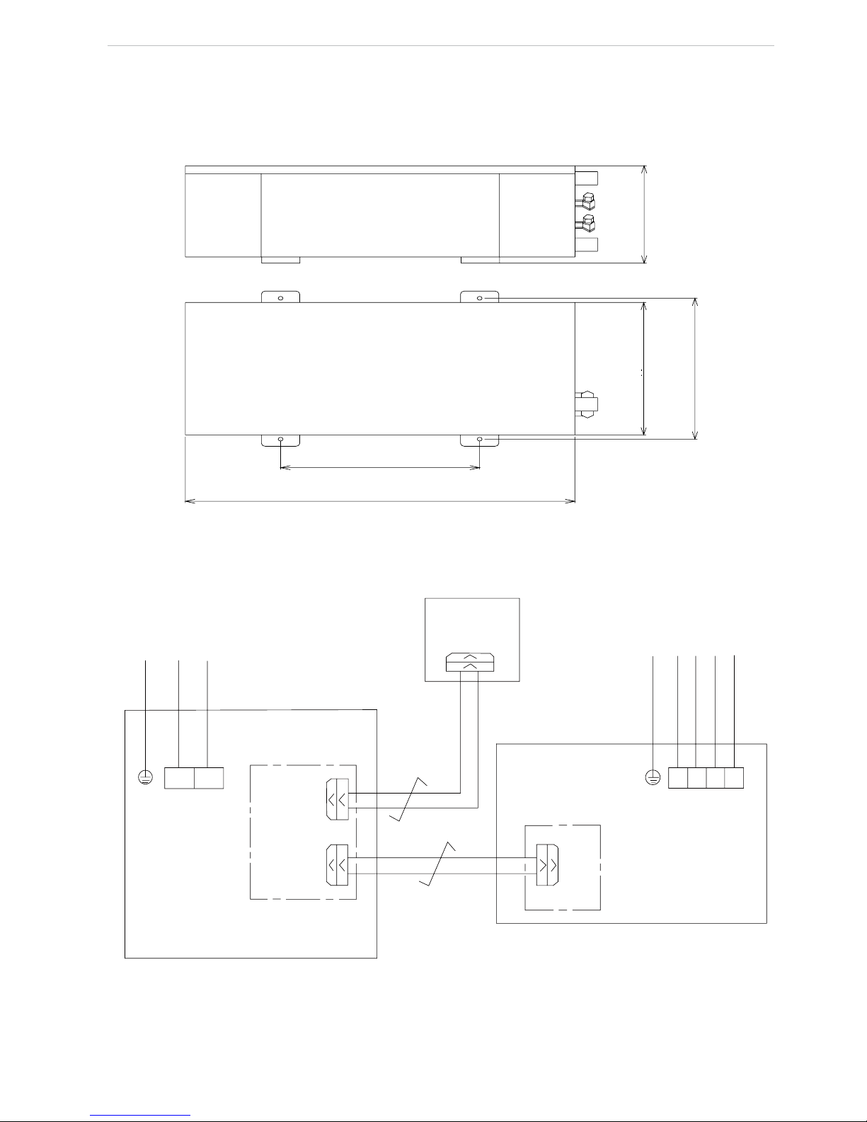
3.2.2 Dimension of Indoor Unit
Outline dimension diagram of HLR8WZNa-M(I)、HLR10WZNa-M(I)、HLR12.5WZNa-M(I)
、
HLR15WZNa-M(I)
Unit: mm
572
1100
450
512
288
3.2.3 Outer Wiring Diagram of Unit
PE
L
PE
L1
L2
L3
N
N
L1
L2
L3
N
L
N
Power:220~240V 50Hz
Power:380~415V 50Hz
Electric conteol box
for indoor unit
Electric conteol box
for outdoor unit
Main board
Display board
Main
board
4-core twisted
pair wire
2-core twisted
pair wire
Page 8

Z series combination household (townhouse)central air conditioning unit
4
4. Operation Instruction to Control
4.1 Display function on display panel
17
16
15
13
12
11
2
1
4
6
7
8
9
10
5
3
14
OFF
ON
EXIT
MODE
CHECK
PARAMETER SET PASSWORD
DEFROST ABC TEST
4.2 LCD displaying panel
1) HEAT: It displays when unit is heating, otherwise it would not display
2) ERROR CODE: It shows the error code displayed on Main Display Area. It displays when there is
error at system or communication.
3) COOL: It displays when cooling is running, otherwise it would not display.
4) TEMP: It shows temperature value displays at main display area.
5) Auxiliary display area: It contains 2 numbers and a comma, for showing temperature and number of
parameter at main display area. It only displays when under Check mode and Parameter checking mode.
6) Main display area: It contains a minus, 2 numbers and 1 temperature unit, for displaying value of
temperature and parameter (temperature or time value) and error code. When temperature value is displayed,
it shows value in algorism and temperature unit; when time is displayed, it shows algorism value but no
temperature unit (default unit is min); when it is code, it displays specic error (refer to Malfunction Error
List) but no temperature unit. Individual temperature or parameter may exceed 99, then adopt AX for 100
~
109, bX for 110~119, CX for 120~129, dX for 130~139, EX for 140~149, FX for 150~159, and X
stands for a number between 0~9. Under normal state, it shows temperature for back water.
7) Parameter list: It means the value shown at present main display area is parameter. It shows onlyunder
Parameter Check mode.
8) DEFROST: It displays when defrosting, otherwise it doesn’t displays.
9) ABC: It displays when system or compressor orders, for showing which system is defrosting.
10) TEST: For testing, it displays under compel operation. 11~17. Buttons: Functions and contents are
shown in instructions for buttons function below.
When unit is off, it displays only temperature of out water. When unit is on, under normal state, if there is
no error, it displays temperature of out water, if there is error, it displays error code; when there is no operation
after 60s of pressing the button, it quit back to normal state display automatically.
Auto antifreeze operation display (only for heat pump unit)
When auto antifreeze function is started and relevant conditions are satised, unit begins auto antifreeze
operation. At this time, LCD main displaying area displays code d2 (if there is error it displays error code).
Page 9

Z series combination household (townhouse)central air conditioning unit
5
4.3 Button function on display board
1) MODE: It can switch between cooling and heating, this button is available only on cooling and heating
unit.
2) Turn On: To turn on the unit; when under compel operation, press once to quid compel operation.
3) Turn Off: To turn off the unit; press it once to quit compel operation when the unit is under compel
operation.
4) ▲ : To increase present set value or change set/check object;
5) ▼: To decrease present set value or change set/check object;
6) Check: Press it once under normal state to enter check mode, under check mode, press this button
when “17” is displayed can change the value of “17”. Under parameter set mode, press this once can switch
the adjusting objection between parameter and value, press this button for long (about 5s) to save and quit this
parameter setting.
7) EXIT: Under Set and Check mode, press it once to quit this mode. Under parameter set mode, this set
value would not be saved. Press this button for long (about 5s) to set sound, and make sound switches between
always on and always off.
8) EXIT +▲: 20s after electrify, press this two buttons simultaneity for about 3s (EXIT rst, and then
▲, the interval between pressing the two buttons should not be longer than 4s), to enter parameter check
mode.
4.4 Buzzer
When unit is always off, buzzer will not sound under any circumstance. When unit is always on, buzzer
sounds once when electried reset and quick test. It also sounds when button is pressed and when there is key
error under unit on state. When unit is operating in anti-high temperature or antifreeze, buzzer doesn’t sounds.
4.5 Basic operation
1) Turn On: Press On once when unit is off then unit be in waiting state, and LCD displays temperature
of water back and operation mode (cooling or heating). When it detected there is terminal on, unit operates
automatically and operation mode blinks; if it detected there is no terminal on, unit turns off after delaying for
certain time, then system back to waiting state.
2) Turn Off: Press OFF once when unit is on to stop the unit from working and make it in off state. At
that time, LCD only displays temperature for back water.
3) Mode Switch: It is only available to heat pump unit, cooling only unit only contains cooling mode.
To heat pump unit, press Mode once, then system mode switches to cool from the previous heating, or to heat
from present cooling. When there is error, this button doesn’t work.
4) Check system temperature point and state: Press Check once to enter check mode. Under check
mode, Auxiliary display area shows checking object, main display area shows the value of the object. Press
▲ and ▼ to change the check object, press EXIT to quit from check mode. The content that can be check are
as follow:
0:Temperature for back water
1:Temperature for out water
2:Outdoor ambient temperature
3:Antifreeze temperature 1
4:Antifreeze temperature 2
5:Defrost temperature 1 (This temperature has no meaning to cooling only unit)
6:Defrost temperature 2 (This temperature has no meaning to cooling only unit)
Page 10

Z series combination household (townhouse)central air conditioning unit
6
7:Exhaust temperature 1
8:Exhaust temperature 2
9:Unidentied
10:Unidentied
11:Real time error code
12:Defrost and terminal =0XH is no defrosting; =FXH is defrosting;
=
X0H means no terminal is on; =XFH means there is terminal on.
13:Outdoor unit operation state: 0x01= Turn off unit when cooling, 0x02= Turn off unit when heating
0x11= Turn on unit when cooling, 0x12= Turn on unit when heating
0xd2= Auto antifreeze is running, 0xF1= Compel cooling, 0xF2=
Compel heating
14:Outdoor unit operation state
15:Indoor unit operation state :
0x01= Turn off unit when cooling, 0x02= Turn off unit when heating
0x11= Turn on unit when cooling, 0x12= Turn on unit when heating
0xd2= Auto antifreeze is running, 0xF1= Compel cooling, 0xF2= Compel heating
16:Indoor unit operation state
17:=00 is stopping auxiliary heating, stopping antifreeze; =01 is turning on auxiliary heating, stopping
antifreeze; =02 is stopping auxiliary heating, turning on antifreeze; =03 is turning only auxiliary heating,
turning on antifreeze (it has no meaning to cooling only unit).
18:Communication state
19:Error in history
5)
Turn On/Off Auxiliary Heater: It is only available for heat pump unit. Press Check once to enter
Check mode. Press ▲ and ▼ to change check object, press Check again till the present check object becomes
“17”, value “17” switches between 01/03 (auxiliary heater on) and 00/02 (auxiliary heater off). That is 00 Off
—>01 On —>00 Off, or 02 Off —>03 On —>02 Off.
6)
Check Parameter: After electrify for 20s, press EXIT then ▲ to enter parameter checking mode.
Under this mode, Auxiliary display area shows the checking object, Main display area displays the value
for the checking object. Press ▲ and ▼ to change the checking object. Press EXIT to quit from the check
mode. Content that can be checked are shown below: Name for Parameter
:
NO. Name for Parameter
0 If auxiliary heater is on
1 Set temperature for cooling water out
2 Set temperature for heating water out
3 Begin temp. for defrost
4 End temp. for defrost
5 Set interval between defrost
6 Duration for defrost
7 Antifreeze temp.
8 End temp. for antifreeze
9 Anti overheated temp.
10 Temp. to quit from anti overheated
11 Deviation to set temp.
12 Outdoor ambient temp. for defrost
13 Exhaust pipe high-temp. protect temp.
14 Interval between terminals off and host stops
Page 11

Z series combination household (townhouse)central air conditioning unit
7
4.6 Error Code List
Error code Meaning for Error Method of Clearing Error
E1 Compressor 1 high-pressure protection Press OFF to clear
E2 System-antifreeze protection Resumes automatically
E3 Compressor 1 low-pressure protection Press OFF to clear
E4 Compressor 1 exhaust temp. protection Press OFF to clear
E5 Compressor 1 overload protection Press OFF to clear
E6 Water pump overload protection Press OFF to clear
E7 Water-ow on/off error Press OFF to clear
E8 Fan 1 overload protection Press OFF to clear
E9 System 1 anti high-temp. Resumes automatically
b1 Compressor 2 high-pressure protection Press OFF to clear
b2 System 2 antifreeze protection Resumes automatically
b3 Compressor 2 low-pressure protection Press OFF to clear
b4 Compressor 2 exhaust temp. protection Press OFF to clear
b5 Compressor 2 overload protection Press OFF to clear
b8 Fan 2 overload protection Press OFF to clear
b9 System 2 anti-high temp. Resumes automatically
F1 Antifreeze temp. sensor 1 error Resumes automatically
F2 Antifreeze temp. sensor 2 error Resumes automatically
F3 Defrost temp. sensor 1 error Resumes automatically
F4 Defrost temp. sensor 2 error Resumes automatically
F5 Exhaust temp. sensor 1 error Resumes automatically
F6 Exhaust temp. sensor 2 error Resumes automatically
F7 Outdoor ambient temp. sensor error Resumes automatically
F8 Water-in temp. sensor Resumes automatically
F9 Water-out temp. sensor Resumes automatically
EC Communication malfunction Resumes automatically
1) Auto reset: It means after error is cleared and compressor stop protection time is satised, unit resumes
running automatically.
2) Manual reset: It means manually press OFF to clear error code rst, and then press ON to make the unit
operates after malfunction is cleared.
3) When low-pressure protection is detected for 3 times in consecutive 30min, reset mode changes
to manual mode from auto mode. When overload at compressor and fan motor is detected for 3 times in
consecutive 30min, reset mode changes to manual mode from auto mode. Note:The installation of the
controller must be done by professionals.
Note:The installation of the controller must be done by professionals.
Page 12

Z series combination household (townhouse)central air conditioning unit
8
5. Daily Operation and Maintenance
When adjustment and test had completed, daily operation such as turn on/off unit, switch cooling and
heating, and set parameter etc. are to be done through the manual control that installed indoor.
1) All safety protection equipments have been set before outgoing, please don’t modify them to prevent
damage to the unit.
2) On-off control of fan coil in each room should be individually operated by thermostat and 3-speed
switch installed in each room. When there is no network control between host and fan coil, after the last fan
coil is turned off, host should be stopped.
3) Don’t cut off power after the unit is stopped. If off time is too long (more than 2 days) and power
supply has been cut after stop, power should be supplied for the unit before restarting the unit to reheat the
compressor for more than 6hr ,so that the unit can operate normally.
4) Don’t put things on the unit or its accessories. Keep the space around the unit dry, clean and ventilation
well. Clean it on time when there is much dust on n of condenser to prevent the dust from affecting the
performance.
5) Don’t block the air outlet and air inlet of indoor fan coil. Filter at air inlet should be periodically
cleaned.
6) Antifreeze must be added into water system of heat pump unit according to proportion shown in this
manual. For cooling only unit, when it is not used in winter, do drain out all water in the unit and pipeline to
avoid cracking of heat exchanger, pipes and water pump. If it is not sure whether water in pipeline has been
drained completely, antifreeze must be added into system pipeline. Don’t cut off power after the unit is off to
make automatic antifreeze operation protection effective.
7) For heat pump unit, after long time for not operation, water in the pipeline will share the same
temperature with ambient water, thus, note to anti cool wind in winter when unit is heating; to the situation of
no connected control system between host and fan coil, it is better to turn on host 5~10min before turning on
the unit for heating, then turn on indoor fan coil to heat directly after water in pipeline become warmer; when
there is connected control between host and fan coil, turn on a fan coil rst and turn on host for 5~10min, turn
on the fan coil in room that needs heating after water in pipeline become warmer. These can prevent cool wind
from blowing out in the rst few minutes when fan coil is just turned on.
6. Common Malfunction and Solution
When problem occurs during operation, please contact with local dealer or ofce.
The following phenomena are not malfunctions:
1) When cooling (heating in winter), if load is low (i.e. quantity of fan coils that operate is small),
temperature of system water will be decreased (increased) rapidly, so that antifreeze (anti high-temp)
protection may occur until water temperature return (decline) to setting temp.
2) During heating, heat exchanger will frost for surface temperature of it is lower than outer ambient
temperature and lower than 0℃ so that heat exchanging efciency is affected, thus the control system will
periodically defrost to melt the frost on the surface of heat exchanger.
3) When unit is used in the area where temperature in winter is below 0℃, if system is in standby state
(power is not cut off), and ambient temp. and system water temp. are about 0℃, in order to prevent water
system from freezing and damaging equipments, control system will conduct auto antifreeze operation, and
start water pump and compressor until water temperature reaches safe point.
During dealing with problems, professional personnel can remove malfunctions by referring to the
following table:
Page 13

Z series combination household (townhouse)central air conditioning unit
9
Common error Reason Solution
1. Compressor doesn’t work.
A. Error on power
B. Wire loose
C. Error on relay or insurance
D. Temp. is set too high
E. Error on compressor
●Check and re-tighten
●Check error reason and repair
●Reset
●Replace compressor
2. Fan noise is large
A. Fixing bolt of fan is loose
B. Fan louver touches outer case
or net cover
C. Operation of fan is unstable
●Retighten fan xing bolt
●Check reason and adjust
●Replace the fan
3.Compressor noise is high
A. Liquid hammer produced for
liquid refrigerant ows in
compressor
B. Components inside compressor
are damaged.
●Check if expand valve is
ineffective, temp. sensor
is loose, and repair
●Replace compressor
4. Water pump doesn’t
operate or operates
abnormally
A. Error of power or wiring
B. Error of relay
C. Gas exists in water pipe
●Check out the reason and repair
●Replace relay
●Exhaust all gas
5. Cooling effect is bad.
A. Freon in cooling system leaks
B. Heat preservation of water
pipe is bad.
C. Water ow quantity is not enough
D. Heavy dust on condenser
E. Cooling system is blocked
●Check and repair or recharge
Freon.
●Strengthen heat preservation
●Clean water lter
●Clean condenser
●Check or replace dry lter
6. ompressor frequently is on
and off.
A. Too much refrigerant
B. Circulation of water system is bad
C. Low load
●Discharge some refrigerant
●Water system is blocked or there is
air.Check water pump, valve, pipeline,
clean water lter or exhaust air.
●Adjust load or increase energy store
facility.
7. Refrigerate system low-
pressure switch on/off is
working frequently.
A. Freon leakage on system and
refrigerant shortage.
B. Dry lter is blocked
C. Error on heat expand valve.
D.Water system circulation is bad
●Check and repair and recharge
refrigerant.
●Change dry lter
●Check if expanse valve is blocked,
temp. sensor is leaking, then repair or
8. ompressor
A. All refrigerant is leaked
.
B. Casing evaporator is freeze.
C.Compressor error
●Check, repair o r charge refrigerant
●Check, reason and remove freezing
●Replace compressor
Page 14

Z series combination household (townhouse)central air conditioning unit
10
7. Terminal Facilities and Selection Guideline
Household (Townhouse) Central Air Conditioning Terminal Facilities are mainly for the heat exchanger
facilities installed indoor, it is commonly for fan coil that is with several models for option. Such as
horizontal invisible fan coil, horizontal visible fan coil, vertical visible fan coil, suspending fan coil and
so on. User can select different type of fan coil according to house structure and indoor decoration style.
To common situation, we recommend selecting horizontal invisible fan coil, for to other fan coil, it is
in smaller dimension and can be concealed well, it is easy for indoor decoration. At the same time, its
noise index is lower, and it is relatively cheaper. Recommended selection suggestions are as following:
Models FP-34 FP-51 FP-68 FP-85 FP-102 FP-136
Room area m
2
8~12 10~18 15~25 20~30 25~35 30~45
Control to the fan coil at every room is conducted by the temperature control on wall and the 3-speed
switch. Temperature control is for setting room temperature, 3-speed switch, with high, medium, and low
speeds, for adjusting airow and cooling capacity of the fan coil. 8. System Installation .
8. System Installation
Do have the unit installed by authorized company or professional central air conditioning installation
project company, don’t try to install it by yourself.
8.1 Unit Installation
8.1.1 Selection of installation location
1) This Household (Townhouse) unit can be installed on roof, ceiling, special at or other place that is
easy for installation and should be able to stand its weight.
2) Select a place with well ventilation and smooth exhausting, and the place will not produce short-circuit
circulation, and where exhausted air from the unit will not bother neighbors.
3) When placing the unit at roof, please note wind direction to prevent direct upwind; when placing it on
ground, do not avoid place it at where there is strong wind.
4) There should be no heat source, exhaust vent of other facilities, strong steam and ammable gas around
the unit.
5) When installing several units, ensure there is enough suction space to prevent short-circuits circulation.
6) Place where is far away heavy snow in winter.
7) There should be no obstruction near air intake vent or air outlet vent.
8) Place where with drainage pipe around the unit to drain cooling or heating water.
9) Place the unit near power for easy wiring.
10) Place the unit near the water source for convenient pipe construction.
11) There should be open space around the unit.
Page 15

Z series combination household (townhouse)central air conditioning unit
11
8.1.2 Installation space requirement for outdoor unit
Whole installation:
Indoor
unit
M10 bolt
Outdoor
unit
L4
L2
L1
Air outlet vent
L2
Air intake vent
Unit: mm
Shown distance L1 L2 L3 L4
Distance >500 >1000 >500 >500
Split type installation:
Installation for outdoor unit
L2
L4
L1
L3
Air intake vent
Air outlet vent
Unit: mm
Shown distance L1 L2 L3 L4
Distance >500 >1000 >500 >500
Page 16

Z series combination household (townhouse)central air conditioning unit
12
Installation for indoor unit
L1
Nut with washer
Spring washer for nut
L2
L3
Unit: mm
Shown distance L1 L2 L3
Distance >250 >800 <1200
8.1.3 Carrying and disassembly
1) It is better to use forklift or crane when moving the unit.
2) When suspending, please adopt canvas gallus, round the gallus at base of the unit and bundle it tightly,
meanwhile, ensure that the gallus would not tough heat exchanger.
3) When moving the unit, the slant angle should be lower than 30 °
8.1.4 Installation mode
1) Directly x the unit on separate concrete base with expand bolts.
2) It is also available to adopt angle iron or steel supporter that make off channel steel, add shake-
absorbing gaskets,and then place the unit on oor or roof, Ensure to keep the unit horizontally.
8.2 Installation of terminal facilities
Installation of indoor terminal fan coil should obey the installation regulation for air conditioning
facilities.
1) Suspend the fan coil according to the elevation shown on air conditioning project construction chart,
and please be aware to keep it horizontally.
2) Connect water in and out water and water in and out joint of fan coil by soft joint; connect condensate
water out pipe on water tray and condensate water drainage host by plastic host.
3) Electric wiring of fan coil, 3-speed switch and temperature control are as following:
Page 17

Z series combination household (townhouse)central air conditioning unit
13
Electric wiring diagram for no connection net control between fan coil and host
Fan coil Fan coil
Electric
valve
Temperature
control
Temperature
control
Temperature
control
N
M
M
M
M
M
M
L
E
...
Terminal switch board
(One can connect to 8
terminals in max.)
X1
X2
X7
Main board for indoor
unit of this unit
Electric wiring diagram for connected control between fan coil and host
Notice:
① .
When conduct connected control between fan coil and host, connect the control live wire of
temperature control of fan coil to the X2~X7 on terminal switch board inside electric case of unit through the
on/off of temperature control; then connect the port X1 at switch board to end_switch at main board of indoor
unit. Meanwhile, cancel the port live wire that default strapped to end_switch when outgoing.
② .
When connect control is not conducted between fan coil and host ,please strap the end_switch at main
board to live wire (short connected before outgoing).
③ .
Method of shutting off the power is cutting off the air switch. Contact diatance between the electrodes
of the air switch must be beyond 3 mm.
④ .
Installation should conform to the local electric standard.
⑤ .
The appliance shall be installed in accordance with natioal wiring regulations.
8.3 Water Pipe Connection
During connecting water pipe, please screw off the choke plug at water in pipe and water out pipe,
and then respectively connect the water-in hose and water-out hose with the water-in pipe and water-
out pipe of unit. Please note the following points during constructing:
1) Water connect pipes must be new,do not substitude old pipes for new ones.
2) Construction must be correctly designed and conducted by following the water and heat pipeline design
criteria and standard.
3) Select corresponding pipe diameter according to the given dimension of pipes.
4) There is expand can set in the unit, water ow switch,auto water lling valve,safety valve,and water
M
M
M
M
M
M
Fan coil
Fan coil
Fan coil
Electric
valve
Electric
valve
Electric
valve
N
L
E
Temperature
control
Temperature
control
Temperature
control
Page 18

Z series combination household (townhouse)central air conditioning unit
14
system adopts our Household (Townhouse) Unit standard installation sketch (as shown below).
5) The quantity ratio of electric 2-way valve and electric 3-way valve in water system should refer to
technical criteria (the recommended value is 2:1). And electric 3-way valve must be assembled at the longest
end of water system.
6) Try to decrease the pressure difference between indoor fan coil or main host with water in or out port
of the unit.
7) Do install water lter at water-in pipe of the unit to prevent block at heat exchanger inside the unit.
8) After piping water system, according to relevant criteria for HVAC, conduct leakage test with hydraulic
pressure of 6kgf/cm2 and maintain the pressure for 24h. Ensure that there is no leakage in the integral pipeline
system, then wrap heat preservation layer.
9) After completed piping of water system, conduct contamination drainage to water system. Ensure that
inside of water pipe is clean without contaminations such as rust dregs, so that there will be no blockage in
pipeline and sleeve heat exchanger in the unit and water pump, and make damage to the unit.
10) Exhaust air inside water system, prevent leaving air in the pipe. Auto exhaust valve must be
prepared at the highest point at water return pipe.
11) Drainage valve should be installed at the lowest point of water pipe.
12) Thermometer and hydraulic pressure meter must be set at water-in and water-out pipe of unit for
convenient check when unit is operating.
13) Water pipe must conduct heat preservation and moisture proof, to prevent loss of cooling or heating
capacity and forming condensation water.
14) Inlet water pipe pressure must be lower than 6.2 kgf/cm2 ,otherwise safety valve will open
automatically release pressure. At the same time ,its minimal pressure must be beyond 1.5kgf/cm2.
Warning! Water lter with 60 meshes at least must be installed on water-in pipeline system of
the unit to prevent blocking of casing heat exchanger in the unit and damage to the unit. Do clean it
periodically.
Illustration
1.Air conditioning host 9.Cheek valve
2.Fan coil 10. Flowmeter
3.Rubber soft joint 11.Dranage valve
4.Thcrmometer 12. Electric 2-way valve
5.Pressure meter 13.Electric 3-way valve
6.Cut-off valve 14.Ball valve
7.By pas adjusting valve 15.Auto exhaust valve
8.Y-shape filte 16.Base
Connected with tap water
Standard Installation Sketch for this Household (Townhouse) Unit
8.4 Anti-freezing Notices
1) If heat pump unit is used at where temperature in winter is below 0
℃
, it must be preserved with
insulating material. Add antifreeze according actual situation.
Page 19

Z series combination household (townhouse)central air conditioning unit
15
2) Auto anti-freezing operation is set in control system for assisting system. Its principle is: When unit
is in standby state (don’t cut off power), and ambient temperature and system water temperature is at about
0 degree, control system will start water pump and compressor till water temperature reaches safety point.
Thickness of glycol liquid—freezing point list:
Thickness % Freezing point ℃ Thickness % Freezing point
℃
Thickness % Freezing point
℃
4.6 -2 19.8 -10 35 -21
8.4 -4 23.6 -13 38.8 -26
12.2 -5 27.4 -15 42.6 -29
16 -7 31.2 -17 46.4 -33
In the list: Thickness of glycol is mass thickness.
9. System Adjustment
9.1 Charge of Refrigerated Water to Air Conditioning System
Fill water to the refrigerate water pipe of system from water pipe, meanwhile, conduct auto gas exhaust
from exhaust valve till the integral pipe lled with water, and conrm air in pipe had completely be exhausted.
9.2 Check before Trial Run
9.2.1 Check indoor fan coil
1) Check if power cord connection of all indoor fan coils is correct, and rotation direction of fan motor is
correct.
2) Check if the valve on entrance and exit pipes of fan coil is completely open.
3) Exhaust it from exhaust valve when there is gas inside fan coil.
9.2.2 Check unit
1) Check if the outer appearance of unit and pipeline system is damaged when transporting or conveying.
2) Check if wiring terminals for electric components inside unit is loose, if phase sequence is correct.
3) Check if vane of fan motor would intervene the outer case and net cover when rotating.
4) Check if temperature sensor had inserted well, if it is loose.
9.2.3 Check pipeline system
1) Check if valves at pipeline system is open completely.
2) Check if water has lled the integral pipeline system, if air is exhausted completely.
3) Check if heat preservation to pipeline system is well.
9.3 Trial Run
Trial run can only be conducted after passing all above checking, then do it under the guideline of
professional personnel.
1) Energize and turn on the unit. To the unit that adopts 3-phase power, when wire sequence of power is
in reverse, phase sequence protection works, then fan motor, compressor and water pump will not act. At that
time, cut off power rst, exchange the two phases among the 3-phase then electrify again and turn on the unit.
2) After energization and operation, circle water pump should operates steadily. If it operates unsteadily,
and swing of pressure meter is unstable, there also is air inside water system. At this time, exhaust air
completely through exhaust valve and then turn on the unit. After turning on the unit for 3 minutes, fan and
compressor will start automatically.
Page 20

Z series combination household (townhouse)central air conditioning unit
16
3) After compressor starts, if there is abnormal sound, stop the unit immediately and check it .
4) When cooling in summer, if temperature of water-out Tout≥15℃, compressor starts; if Tout≤7℃,
compressor stops, in which case , water pump keeps on running, cooling capacity of terminal is also supplied
by the refrigerated water in water pipe. During operation of the unit, energy can be automatically adjusted by
intellectual control system according to change of load.
5) If heat pump heats in winter and water-out temperature Tout≤45℃, compressor will begin running; if
Tout≥50℃, compressor will stop, and water pump will keep on running. Heating capacity of terminals is still
supplied by hot water in water pipe.
6) Obverse if water in / out temperature is usual. If temperature difference between in and out water
temperature ∆T>5℃, it means water ow in the system is low, at this time, check if there is blockage in water
lter, air has been exhausted, resistance in pipeline system is too high etc.; it is better when ∆T is between
3-5℃.
7) After trial run, clean the filter on pipeline first, and then the unit can begin normal operation. It is
necessary to disassemble and clean the lter periodically (once a month) to ensure normal operation of the
unit.
Note:
Since the unit adopts total hermetic scroll compressor, phase sequence of power must be correct,
and it is forbidden for operate with reverse power supply for long time.
Note: For above mentioned trial run parameters, please take the latest released control logic as reference.
10. Usage Instruction for Accessories
10.1 Auto water ll valve
Application specification: water-replenishing valve with stabilivolt and pressure-relief equipment can
automatically keep hydraulic pressure of system at a stable value. If
pressure of the system decreases, the valve will open automatically
so that water can be lled in the system. After it reaches set pressure,
valve will close automatically. When water-replenishing valve is
under normal operation, and hydraulic pressure of system is higher
than set pressure, the valve with check function will stop water from
backflow even pressure of system increases. During inspection or
emptying of system, cut-off valve should be manually tightened and
water source should be shut off.
Pressure setting: Setting pressure of water-replenishing valve
is determined by working pressure of system, and can be adjusted
automatically. During adjusting, water-replenishing valve should be
in working state. Connect pressure meter to joint of G1/4", loosen
tightened nut and adjust the pressure adjusting bolt. After pressure is adjusted to working pressure of system,
tighten the nut.
Note: If pressure of water-replenishing source for unit is lower than the set pressure of water-replenishing
valve for a long time (abnormal working state), a one-way valve should be added at the outlet of water-
replenishing valve or manually close the hand wheel of water-replenishing valve. Dimension of joint of water-
replenishing pipe is G1/2".
82.5
G1/4〞
G1/2〞
Tighten nut
Press Handwheelure
adjusting screw
Handwheel
black ABS
Page 21

Z series combination household (townhouse)central air conditioning unit
17
Note:
This accessory h ad been installed inside the u nit, t esting p ersonnel m ust conduct p ressure
setting w hen w ater fill p ressure is lower than 0.15MPa and must according t o actual situation. It
shall be done by professional
10.2 Safety valve
Safety valve is for preventing system pressure from rising suddenly,
such as water hummer, over filled, on-off or failure of valve and
fluctuation of system water temperature with the change of ambient
and load, and uctuation of pressure of system for heat expansion and
shrinking of water capacity. When pressure exceeds setting pressure of
safety valve, the valve will open automatically to release pressure and
prevent damage to system for over- high pressure.
Working pressure of valve should normally be set about 10% higher
than operation pressure of system and be installed at place that is easier
to product pressure convergence, such as near expand water case or
water pump. There usually is a drainage pipe at outlet of valve for easy drainage. User can manually turn the
hand wheel to release pressure.
Note:
This accessory h ad been installed inside the u nit, unprofessional personnel p lease don’t turn or
assemble it.
10.3 Auto exhaust valve
If air in water system can not be exhausted, following effects will
result:
1) Temperature at some parts will be uneven.
2) Noise is produced.
3) Oxygen in the air would cause metal oxygenation .
4) Too much air would damage water pump.
Auto exhaust valve should be installed at the top of pipeline or the
place where gas is easily gathered and be installed vertically. Self-close
valve or cut-off valve should be installed at bottom of exhaust valve for
convenient charging of water or repairing .Exhaust valve cannot be installed at place that is easy be frozen.
46.0
G3/8〞
10.5
70
G1/2〞
G1/2〞
Release pressure
manually
Black ABS
(29)
Page 22

Gree Electric Appliances,Inc. of Zhuhai
Jin Ji West Road, Qianshan, Zhuhai, Guangdong 519070 P.R. China
http: //www. gree. com
GREE 66172102
 Loading...