

Gree Heat Pump Water Heater, KFRS-9/Na-M, GRS-S16/Na-M, GRS-S16/Na-MO Service Manual

Heat Pump Water Heater((((Northern Europe))))
Service Manual
GREE ELECTRIC APPLIANCES INC. OF ZHUHAI

CONTENTS
RODUCT INTRODUCTION.....................................................................................2
1 MODELS LIST............................................................................................................................. 2
2 NOMENCLATURE......................................................................................................................2
3 FUNCTION ..................................................................................................................................3
4 PRODUCT DATA.........................................................................................................................4
4.1 Product Data at Rated Condition........................................................................................4
4.2 Ambient Temp Range.........................................................................................................4
4.3 Electrical Data.................................................................................................................... 5
5 PIPING DIAGRAM...................................................................................................................... 6
UNITS CONTROL......................................................................................................8
1 OPERATION FLOWCHART....................................................................................................... 8
2 MAIN LOGIC............................................................................................................................. 10
2.1 Heating Mode................................................................................................................... 10
2.2 Defrosting Mode..............................................................................................................10
3 WIRED CONTROLLER ............................................................................................................ 11
3.1 Dimension........................................................................................................................ 11
3.2 Function ........................................................................................................................... 11
3.3 Installation........................................................................................................................ 14
4 CONTROL WIRING DESIGN...................................................................................................16
UNITS INSTALLATION..........................................................................................18
1 UNITS INSTALL........................................................................................................................18
1.1 Installation Positions........................................................................................................ 18
1.2 Matters need Attention.....................................................................................................18
1.3 Dimension Date................................................................................................................18
1.4 Installation Clearance Date.............................................................................................. 19
2 ELECTRIC WIRING WORK..................................................................................................... 21
2.1 Wiring Principle...............................................................................................................21
2.2 Electric Wiring Design..................................................................................................... 21
2.3 Specification of Power Supply Wire and Air Switch ....................................................... 22
UNITS MAINTENANCE..........................................................................................24
1 ERROR CODE LIST.................................................................................................................. 24
2 FLOW CHART OF TROUBLESHOOTING ............................................................................. 25
3 DISASSEMBLY AND ASSEMBLY PROCEDURE OF MAIN PARTS.................................... 31
4 EXPLODED VIEWS AND PART LIST..................................................................................... 37
4.1 Single Fan ........................................................................................................................ 37
4.2 Double Fan.......................................................................................................................38

GREE COMMERCIAL AIR CONDITIONERS HEAT PUMP WATER HEATER (NORTHERN EUROPE)
1
PRODUCT
HEAT PUMP WATER HEATER (NORTHERN EUROPE) PRODUCT
2
RODUCT INTRODUCTION
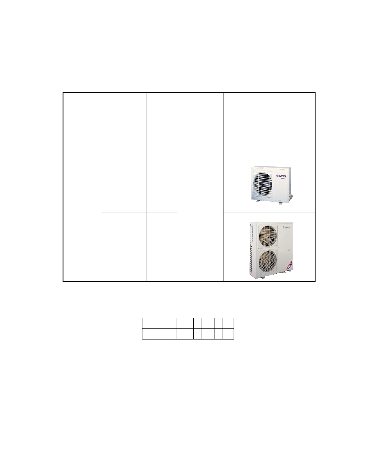
1 MODELS LIST
Model
Refrigerant Model Name
Nominal
Capacity
(kW)
Power Supply
(V,Ph,Hz)
Appearance
KFRS-9/Na-M 9.0
R410A
GRS-S16/Na-M(O) 16
380~415V
3Ph 50Hz
Note:1Ton =12000Btu/h = 3.517kW
2 NOMENCLATURE
K F RS - 9 / Na - M
1 2 3 4 5 6

HEAT PUMP WATER HEATER (NORTHERN EUROPE) PRODUCT
3
NO. Description Options
1 Air Source
2 Split Type F= Split Type, Default= Integral Type
3 Heat Pump Water Heater
4 Heating Capacity 9KW
6 Refrigerant Na=R410A, Default=R22
7 Voltage
M=380~415V 3Ph 50Hz
G RS - S 16 / Na - M (0)
1 2 3 4 5 6 7
NO. Description Options
1 GREE
2 Heat Pump Water Heater
3 Static S= Static ,C =Circulating
4 Heating Capacity 16KW
5 Refrigerant Na=R410A, Default=R22
6 Voltage
M=380~415V 3Ph 50Hz
7 Outdoor Unit O= Outdoor Unit ,I=Indoor Unit
3 FUNCTION
Function Description
Heating
Memory restart
High efficiency and energy saving
Environmentally friendly
Healthy and comfortable
Friendly man-machine interface
Easy installation
Low noise design
Safety and reliability thanks to advance compressor balance control
HEAT PUMP WATER HEATER (NORTHERN EUROPE) PRODUCT
4
4 PRODUCT DATA
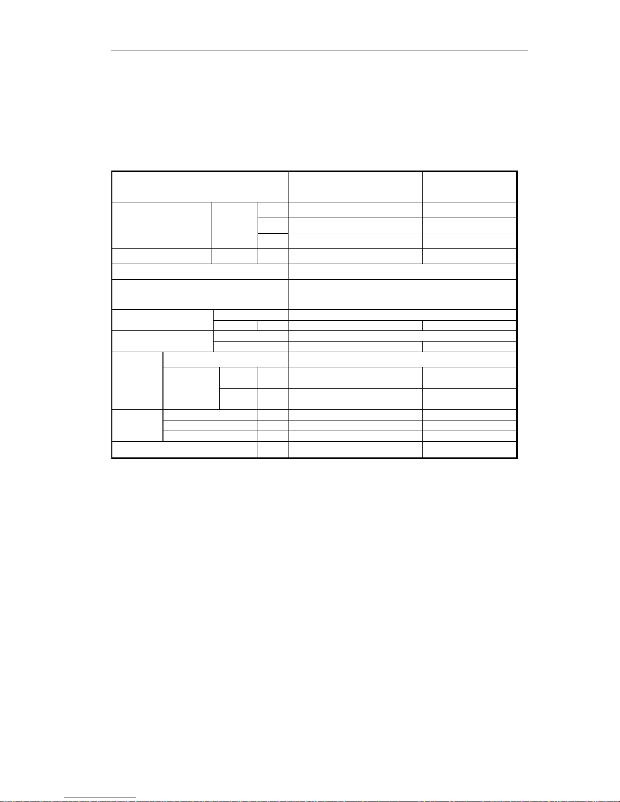
4.1 Product Data at Rated Condition
Technical parameters of host unit
Models
KFRS-9/Na-M GRS-S16/Na-M(O)
kW 9 16
Btu/h 30708 54592
Nominal Capacity Heating
RT 2.56 4.55
Power Consumption Heating kW 3 5.5
Power Supply 380~415V,3Ph,50Hz
Safeties
High/Low pressure switch, compressor thermal
protection, over current protection, lose of
phase/anti-phase protection, antifreeze protection,
Type R410A
Refrigerant
Charge kg 3.3 4.5
Type scroll
Compressor
NO. 1 1
Heat Exchanger Aluminum fin-copper tube
Liquid
mm
1/2"
1/2"
Evaporator
Connection
Pipe
Gas
mm
3/4" 3/4"
Height mm 840/985 1250/1405
Width mm 1018/1110 1032/1110
Unit/
Packing
Dimension
Depth mm 412/450 412/450
Net / Gross Weights
kg
90/100 132/145
NOTE:Testing condition of heating :Setting temp of outlet water: 45℃, outdoor ambient temp : DB7℃/WB6
℃.
4.2 Ambient Temp Range
Ambient temp range of unit during operation: -15~28℃.
HEAT PUMP WATER HEATER (NORTHERN EUROPE) PRODUCT
5
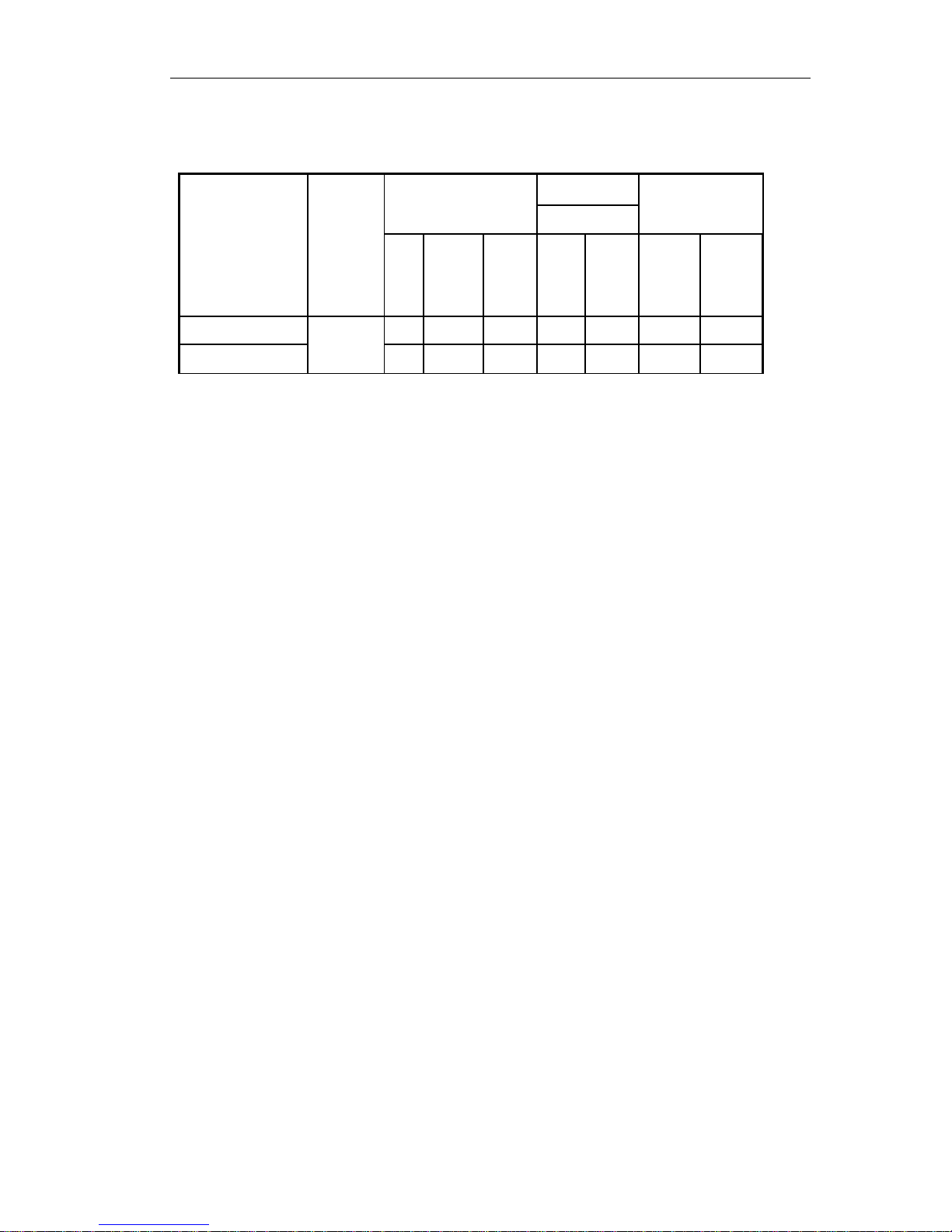
4.3 Electrical Data
Fan Motor
Compressor
Outdoor
Total
Model
Rated
Power
Supply
NO.
LRA
each
(A)
MRC
each
(A)
NO.
MRC
(A)
MRC
(A)
NRC
(A)
KFRS-9/Na-M
1 48 10.8 1 1.5 12.3 8.2
GRS-S16/Na-M(O)
380~415V
3Ph 50Hz
1 74 15.0 2 2 19.5 12.0
Notes:
LRA: Locked rotor amps (A)
MRC: Maximum running current (A)
NRC: Nominal running current (A)
HEAT PUMP WATER HEATER (NORTHERN EUROPE) PRODUCT
6
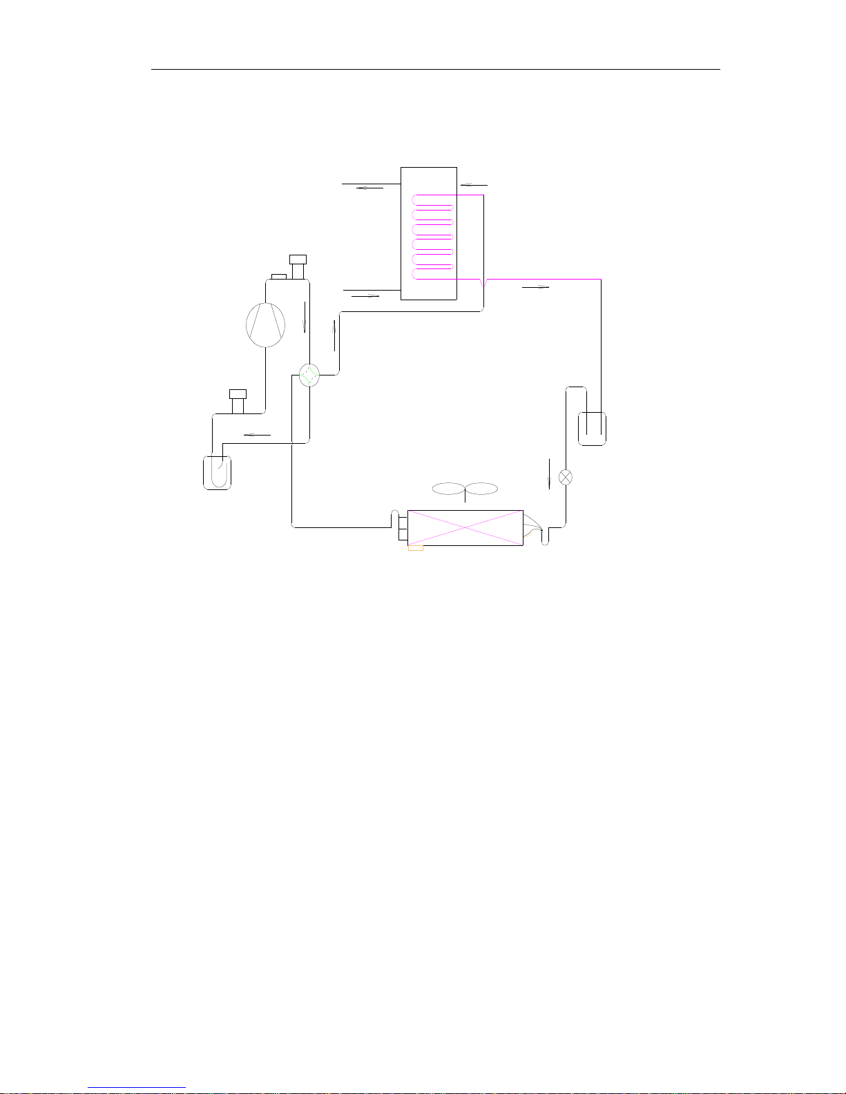
5 PIPING DIAGRAM
Hot water
City water
Thermal expansion valve
Liquid-gas separator
Low-pressure
switch
Compressor
High-pressure
switch
Water tank
Four-way valve
Aluminum fin-copper tube coil
High pressure
tank

GREE COMMERCIAL AIR CONDITIONERS HEAT PUMP WATER HEATER (NORTHERN EUROPE
)
7
CONTROL

GREE COMMERCIAL AIR CONDITIONERS HEAT PUMP WATER HEATER (NORTHERN EUROPE)
8
UNITS CONTROL
1 OPERATION FLOWCHART
HEAT PUMP WATER HEATER (NORTHERN EUROPE) INSTALLATION
9
HEAT PUMP WATER HEATER (NORTHERN EUROPE) INSTALLATION
10
2 MAIN LOGIC
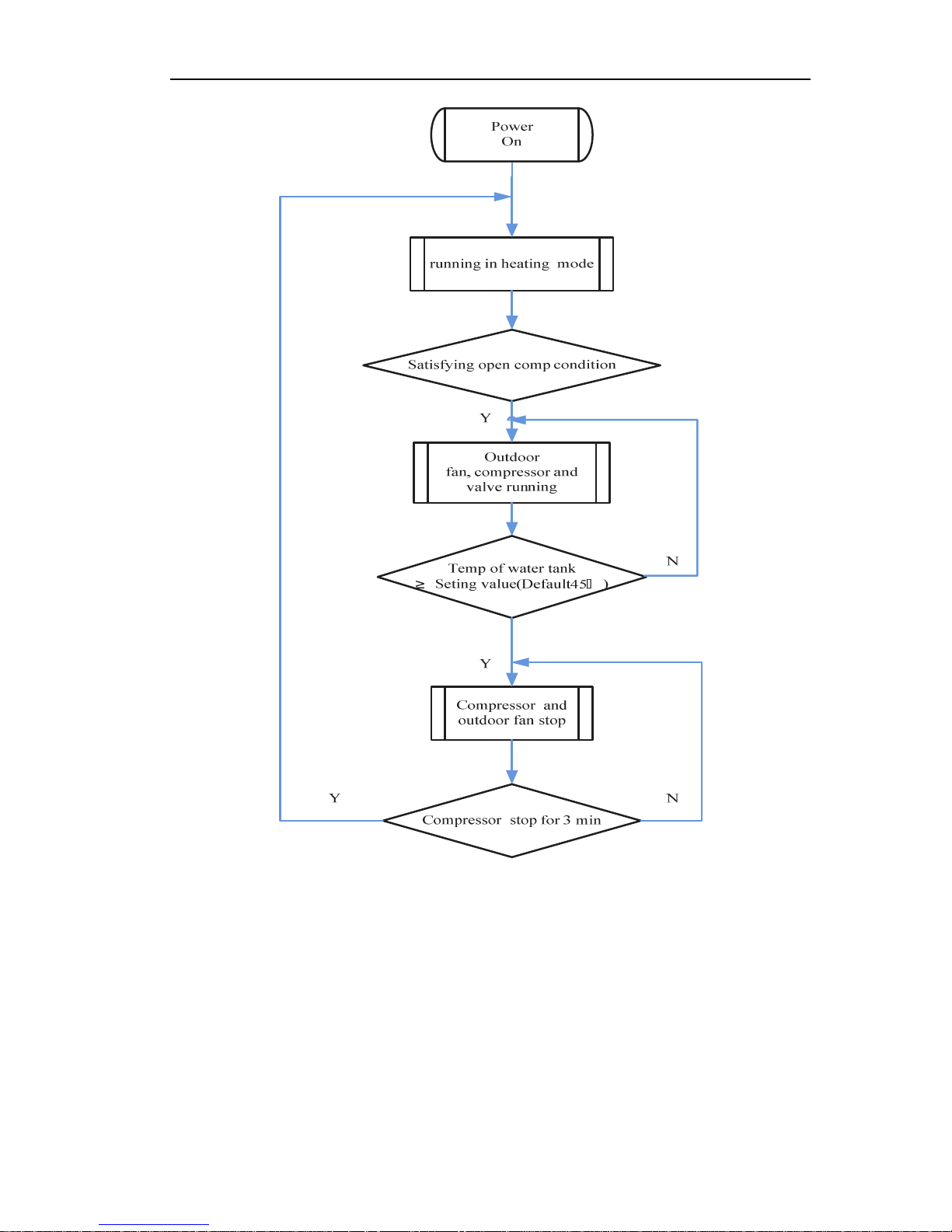
2.1 Heating Mode
When press ON button, if the temperature of water tank meets the heating running requirements,
it starts the fans of outdoor unit. Then the compressor will run after 15s.
If the temperature of water tank is over the set temperature , the unit will stop, and turn off all
loads .The fans of outdoor unit will stop after 15s.
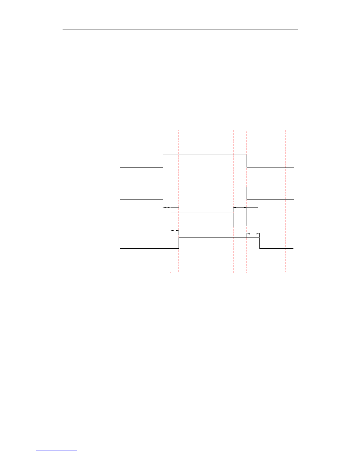
Turn on
Fan
1
Compressor
Turn off
Four-way Valve
15S
Fan
2
When it is turned off
15S
5S
30S
When it is turned off
2.2 Defrosting Mode
The condition of start defrosting mode:
Under heating mode, if the accumulative running time of compressor is over the set interval time
of defrosting(default 45min),and the defrosting temperature is lower than the set starting
temperature(default -4℃) ,the unit will start running defrosting mode, and the 4-way valve will shut

HEAT PUMP WATER HEATER (NORTHERN EUROPE) INSTALLATION
11
off and the outdoor fan will stop after 2s.
The condition of quit defrosting mode:
Under defrosting mode, if the continual defrosting time is over the set continual time of defrosting
(default 8min),and the defrosting temperature is over the set stopping temperature(default 20℃) ,the
unit will restart running heating mode, and the 4-way valve will turn on and the outdoor fan will run.
3 WIRED CONTROLLER
3.1 Dimension
3.2 Function
3.2.1 Operation View
 Loading...