

Gree GWH12MB-A3DNA3A, GWH36LB-D3DNA3E, GWH24MD-D3DNA3D, GWH30LB-D3DNA3E, GWH12MB-D3DNA3D Installation, Service & Troubleshooting
...
Neo
DUCTLESS SYSTEM
Installation, Service & Troubleshooting
Models:
GWH09MA-A3DNA3A
GWH12MB-A3DNA3A
GWH09MB-D3DNA3D
GWH12MB-D3DNA3D
GWH18MC-D3DNA3D
GWH24MD-D3DNA3D
GWH30LB-D3DNA3E
GWH36LB-D3DNA3E

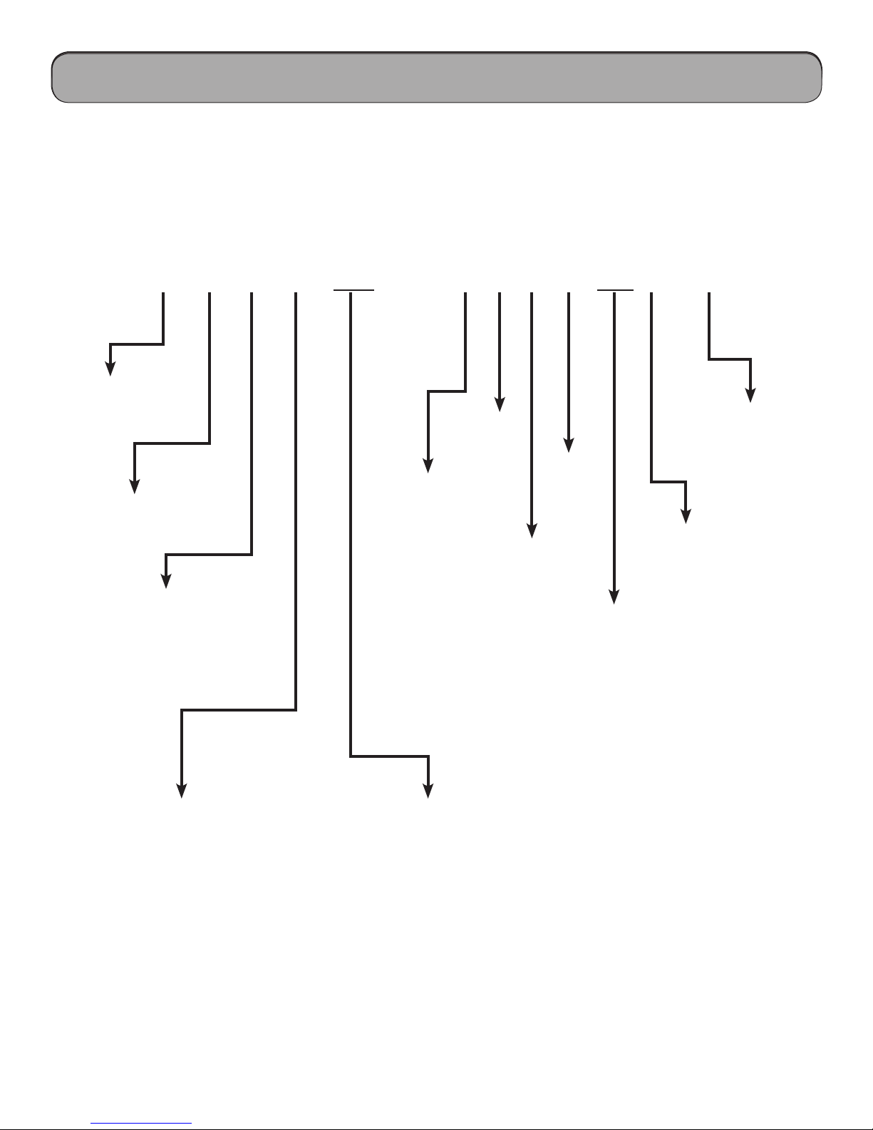
Table of Contents
Safety Precautions & Warnings.........................................................................................................................
Model Number Identication............................................................................................................................
Physical & Electrical Data.................................................................................................................................
System Overview.................................................................................................................................................
Refrigeration Cycles and Components............................................................................................................
Indoor & Outdoor Components.......................................................................................................................
Basic & Protection Functions............................................................................................................................
Remote Control Operation................................................................................................................................
Refrigerant Lines, Connection, Evacuating and Charging............................................................................
Installation, Filter Maintenance and Emergency Operation.........................................................................
Electrical Schematics..........................................................................................................................................
4
5
6 - 9
10
11 - 15
16 - 18
19 -52
53 - 57
58 - 66
67
68 - 79
Outdoor Printed Circuit Board..........................................................................................................................
Troubleshooting Indoor Components..............................................................................................................
Troubleshooting Outdoor Components...........................................................................................................
Fault Codes & Status Displays...........................................................................................................................
Troubleshooting Flow Charts............................................................................................................................
Fault Codes, Diagnostics & Status Displays.....................................................................................................
Disassembly of 115 volt Indoor Units...............................................................................................................
Disassembly of 9,000 & 12,000 btuh 120 volt Outdoor Systems..................................................................
Disassembly of 9,000 btuh 240 volt Indoor Systems.....................................................................................
..
Disassembly of 9,000 btuh 240 volt Outdoor Systems..................................................................................
Disassembly of 12,000 btuh 240 volt Outdoor Systems.................................................................................
80
81 - 82
83 - 92
93 - 127
128 - 139
140 - 160
161 - 163
164 - 167
168 - 170
171 - 174
175 - 178
Disassembly of 18,000 btuh 240 volt Outdoor Systems.................................................................................
2
179 - 183

Table of Contents
Disassembly of 24,000 btuh 240 volt Outdoor Systems.................................................................................
Disassembly of 240 volt Indoor Systems.........................................................................................................
Disassembly of 30,000 & 36,000 240 volt Indoor Systems...........................................................................
Appendix 1 - 3 Temperature Sensor Resistance Tables..................................................................................
184 - 188
189 - 197
198 - 204
205 - 210
3
Safety Precautions & Warnings
!
Installing, starting up, and servicing air conditioner can be
hazardous due to system pressure, electrical components,
and equipment location, etc. Only trained, qualied
installers and service personnel are allowed to install, startup, and service this equipment. Untrained personnel can
perform basic maintenance functions such as cleaning
coils. All other operations should be performed by trained
service personnel. When handling the equipment, observe
precautions in the manual and on tags, stickers, and labels
attached to the equipment. Follow all safety codes. Wear
safety glasses and work gloves. Keep quenching cloth and
re extinguisher nearby when brazing. Read the instructions
thoroughly and follow all warnings or cautions in literature
and attached to the unit. Consult local building codes and
current editions of national as well as local electrical codes.
Recognize the following safety information:
Warning: Incorrect handling could result in
!
personal injury or death.
Caution: Incorrect handling may result in minor
!
injury, or damage to product or property.
Warning
!
• Never install the unit in a place where a combustible
gas might leak, or it may lead to re or explosion.
• Make a proper provision against noise when the unit is
installed at a telecommunication center or hospital.
• Provide a GFIC circuit when the local or national
electric code requires it.
• Never wash the unit with water.
• Handle unit transportation with care. Use two people
when the weight exceeds the capacity for one person.
• Never touch the heat exchanger ns with bare hands,
sharp edges could cause personal injury.
• Never touch the compressor or refrigerant tubing
without proper hand protection.
• Do not operate th unit without the air lters in place.
• Should any emergency occur, stop the unit and
disconnect the electrical supply.
• Properly insulate tubing running inside the room to
prevent water damage from condensation.
!
All installation or repair work shall be performed by your
dealer or a specialized subcontractor as there is the risk of
re, electric shock, explosion or injury
Caution
Warning
!
Warning
All electrical work must be performed by a qualied,
licensed electrician according to local and national
codes as well mas the instructions provided in the
manual.
• Before installing, modifying, or servicing the
system, the main electrical disconnect must be o.
ere may be more than one disconnect switch.
Lock out and tag switch with a suitable warning
label.
• Never supply power to the unit unless all wiring and tubing are completed, reconnected and
checked.
• is system adopts highly dangerous electrical
voltage. Incorrect connections or inadequate
grounding can cause personal injury or death.
Refer to your local and national codes for proper
grounding.
• Have the unit properly grounded with all connections tight. Loose connections can cause overheating and a possible re hazard.
!
Warning
Pressurized Refrigerant
Personal injury could result in failure to follow this warning.
Systems contain oil and refrigerant under high pressure,
proper refrigerant handling techniques should be
completed by a qualied technician.
!
Warning
Live Electrical Components
Personal injury, property damage, or death could result in
failure to follow this warning.
Follow all electrical precautions when servicing this
system, it may be necessary to service or troubleshoot with
live electrical circuits. All work should be completed by a
qualied technician.
4
Safety Considerations & Warnings
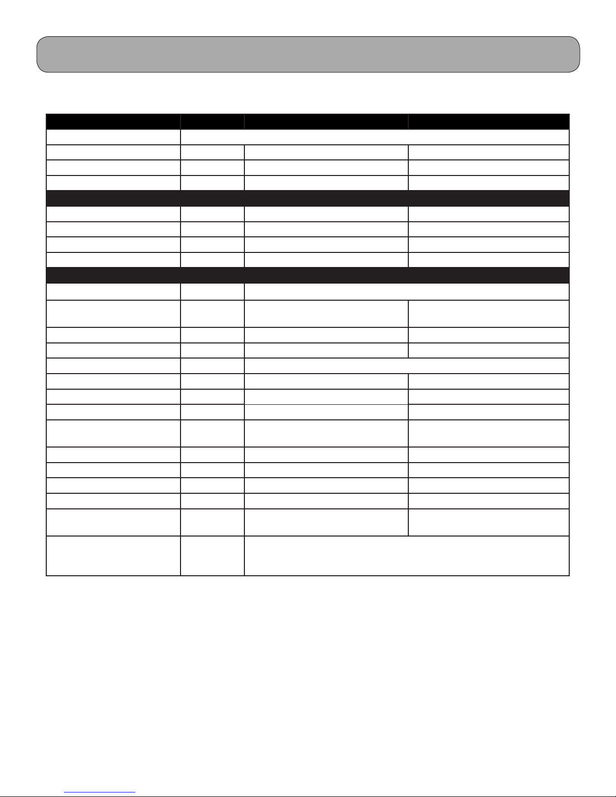
Model Number Identication
Model Number Identication
Product Catalog Number-Nomenclature
G W H 09 MA - A 3 D N A 2 B / I
GREE
I - Indoor Unit
R410a
O - Outdoor Unit
Wall Mount
C - Cooling
H - Heat Pump
09 - 9,000 btuh
12 - 12,000 btuh
18 - 18,000 btuh
24 - 24,000 btuh
30 - 30,000 btuh
36 - 36,000 btuh
42 - 42,000 btuh
A - 115 vac
D - 208/230 vac
DC Inverter
Product Series
Terra - TB/TC/TD
Neo - AB/AC
Neo Multi - ND
NEO - MA/MB/MC/MD/LB
RIO - KF/KG
T1
Revision #
Panel #
5
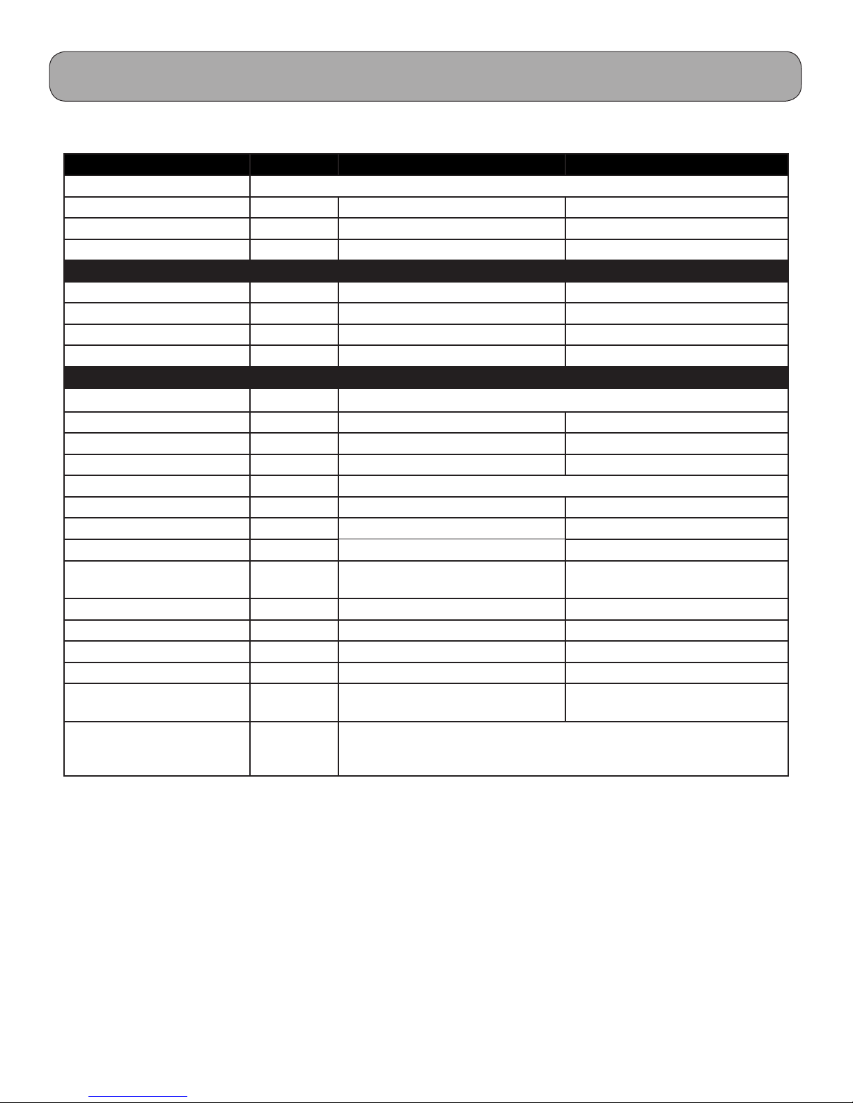
Physical & Electrical Data, cont.
Model GWH09MA-A3DNA3A GWH12MB-A3DNA3A
System Type Heat Pump
Power Supply 115V / 60Hz 115V / 60Hz
Rated Current Cooling Amps Standard 7.0 / High 16.8 Standard 11.0 / High 17.0
Rated Current Heating Amps Standard 7.5 / High 17.0 Standard 12.5 / High 18.2
System Performance
Cooling Cap (Min/Max) Btu/h 9,000 (4435-12000) 12,000 (4,500-14,000)
Heating Cap (Min/Max) Btu/h 9,500 (3200-12500) 13,000 (3,250-14,500)
Operating Range - Cooing deg F 55 - 115 55 - 115
Operating Range - Heating deg F 5 - 75 5 - 75
System Specications
Compressor Type DC Inverter-Driven Twin Rotary
Sound Level (Indoor/Outdoor)
Net/Gross Weight Indoor lb 24 / 31 24 / 31
Net/Gross Weight Outdoor lb 79 / 90 88 / 97
Condenser Coil Type Gold Fin Coated
Refrigerant/Charge oz R410a / 41.2 R410a / 45.9
Line Set Size Liq. - Suction 1/4” - 3/8” 1/4” - 3/8”
Pre-Charged Lineset Ft. Feet 25 25
Additional Refrigerant
charge/additional feet
Max. Total Piping Length Feet 50 50
Max. Elevation Feet 33 33
MCA Amps 20 20
MOCP/Breaker Size Amps 30 30
Wire Size to Outdoor Unit, #
of Wires per Local Code
Wire Size and # of Conductors from Indoor to Outdoor
unit
db <=44 / <=63 <=46 / <=65
oz 0.22 0.22
awg 10 10
14awg/4c
Note: The manufacturer reserves the right to modify the design and/or change the specications without notice. Please
Note: The manufacturer reserves the right to modify the design and/or change the specications without notice. Please
refer to specic installation manual for current information.
refer to specic installation manual for current information.
6

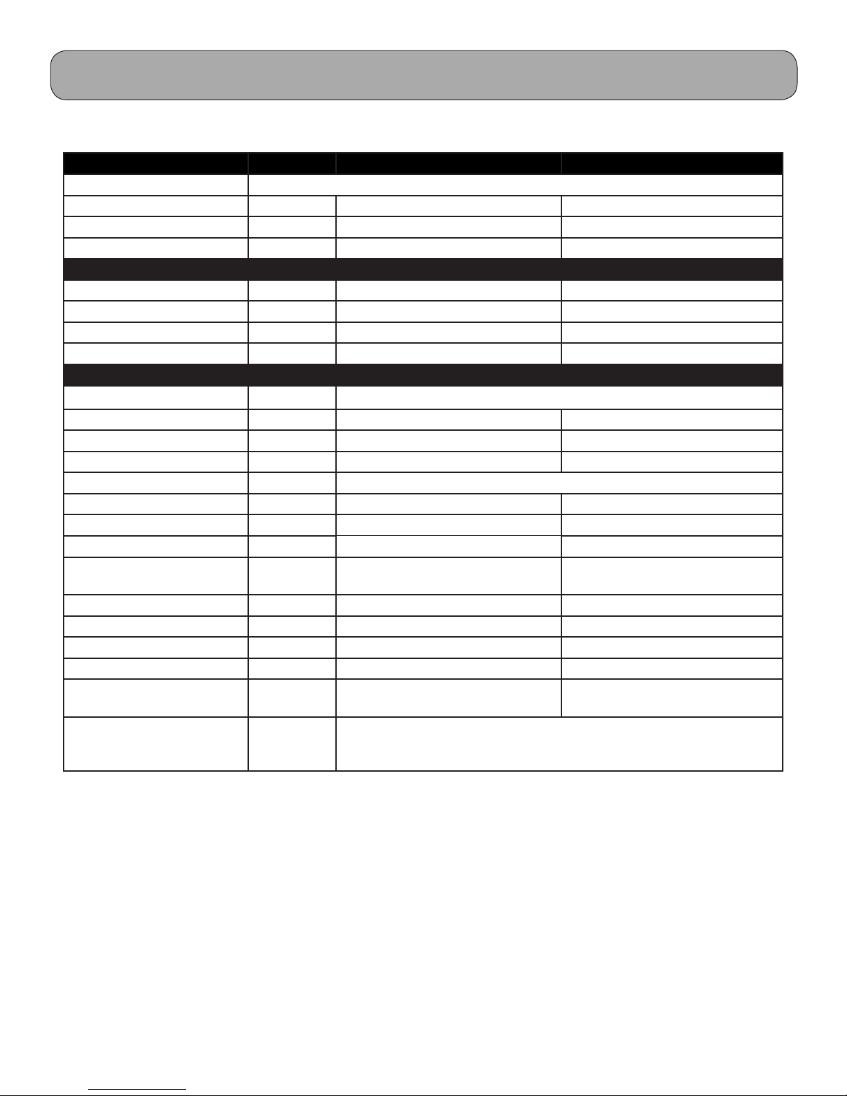
Physical & Electrical Data, cont.
Model GWH09MB-D3DNA3D GWH12MB-D3DNA3D
System Type Heat Pump
Power Supply 208 / 230v / 60Hz 208 / 230V / 60Hz
Rated Current Cooling Amps 2.8 4.5
Rated Current Heating Amps 3.0 5.2
System Performance
Cooling Cap (Min/Max) Btu/h 9,000 (3,500-9,600)) 12,000 (3,100-13,500)
Heating Cap (Min/Max) Btu/h 9,800 (2,200-11,000) 13,000 (2,400-14,000)
Operating Range - Cooing deg F 5 - 109 5 - 109
Operating Range - Heating deg F 5 - 75 5 - 75
System Specications
Compressor Type DC Inverter-Driven Twin Rotary
Sound Level db 50 52
Net/Gross Weight Indoor lb 22 / 29 22 / 29
Net/Gross Weight Outdoor lb 79 / 90 88 / 97
Condenser Coil Type Gold Fin Coated
Refrigerant/Charge oz R410a / 45.9 R410a / 45.9
Line Set Size Liq. - Suction 1/4” - 3/8” 1/4” - 3/8”
Pre-Charged Lineset Ft. Feet 25 25
Additional Refrigerant
charge/additional feet
Max. Total Piping Length Feet 50 66
Max. Elevation Feet 33 33
MCA Amps 10 10
MOCP/Breaker Size Amps 15 15
Wire Size to Outdoor Unit, #
of Wires per Local Code
Wire Size and # of Conductors from Indoor to Outdoor
unit
oz 0.22 0.22
awg 14 14
14awg/4c
Note: The manufacturer reserves the right to modify the design and/or change the specications without notice. Please
refer to specic installation manual for current information.
7
Physical & Electrical Data, cont.
Model GWH18MC-D3DNA3D GWH24MD-D3DNA3D
System Type Heat Pump
Power Supply 208-230v / 60Hz 208-230V / 60Hz
Rated Current Cooling Amps 6.7 7.9
Rated Current Heating Amps 7.3 9.3
System Performance
Cooling Cap (Min/Max) Btu/h 18,000 (5,970-22,350) 21,400 (9,600-25,000)
Heating Cap (Min/Max) Btu/h 19,800 (4,100-22,000) 23,000 (4,300-26,000)
Operating Range - Cooing deg F 25 - 115 25 - 115
Operating Range - Heating deg F 5 - 65 5 - 65
System Specications
Compressor Type DC Inverter-driven Twin Rotary
Sound Level db 56 58
Net/Gross Weight Indoor lb 29 / 38 35 / 46
Net/Gross Weight Outdoor lb 99 / 110 132 / 146
Condenser Coil Type Gold Fin Coated
Refrigerant/Charge oz R410a / 49.4 R410a / 56.4
Line Set Size Liq. - Suction 1/4” - 1/2” 1/4” - 5/8”
Pre-Charged Lineset Ft. Feet 25 25
Additional Refrigerant
charge/additional feet
Max. Total Piping Length Feet 82 82
Max. Elevation Feet 33 33
MCA Amps 13 16
MOCP/Breaker Size Amps 20 25
Wire Size to Outdoor Unit, #
of Wires per Local Code
Wire Size and # of Conductors from Indoor to Outdoor
unit
oz 0.22 0.5
awg 12 10
14awg/4c
Note: The manufacturer reserves the right to modify the design and/or change the specications without notice. Please
refer to specic installation manual for current information.
8
Physical & Electrical Data, cont.
Model GWH30LB-D3DNA3E GWH36LB-D3DNA3E
System Type Heat Pump
Power Supply 208-230v / 60Hz 208-230V / 60Hz
Rated Current Cooling Amps 12.1 15.9
Rated Current Heating Amps 12.5 15.5
System Performance
Cooling Cap (Min/Max) Btu/h 28,000 (9,500-30,000)) 33,600 (7,400-36,000)
Heating Cap (Min/Max) Btu/h 28,400 (10,000-33,000) 34,600 (15,000-36,000)
Operating Range - Cooing deg F 25 - 115 25 - 115
Operating Range - Heating deg F 5 - 65 5 - 65
System Specications
Compressor Type DC Inverter-driven Twin Rotary
Sound Level db 50 52
Net/Gross Weight Indoor lb 22 / 29 22 / 29
Net/Gross Weight Outdoor lb 75 / 90 88 / 97
Condenser Coil Type Gold Fin Coated
Refrigerant/Charge oz R410a / 84.7 R410a / 91.7
Line Set Size Liq. - Suction 1/4” - 5/8” 1/4” - 5/8”
Pre-Charged Lineset Ft. Feet 25 25
Additional Refrigerant
charge/additional feet
Max. Total Piping Length Feet 100 100
Max. Elevation Feet 33 33
MCA Amps 20 24
MOCP/Breaker Size Amps 30 35
Wire Size to Outdoor Unit, #
of Wires per Local Code
Wire Size and # of Conductors from Indoor to Outdoor
unit
oz 0.5 0.5
awg 10 8
14awg/4c
Note: The manufacturer reserves the right to modify the design and/or change the specications without notice. Please
refer to specic installation manual for current information.
9

Product Introduction
System Overview
e Neo Ductless split heat pumps are single zone
units available in size from 9000 btuh to 36,000 btuh
providing heating and cooling. All comfort settings are
controlled by a remote control. e Neo unit has many
features to enhance comfort and eciency. e operation of these features will be explained later in this
service manual.
Superior inverter technology is used to control capacity while maintaining maximum eciency. e
Neo systems are equipped with G10 inverter technology providing precise control over the compressor
frequency based on operating pressures and temperatures. Should an abnormal condition occur, the
soware will adjust the compressor frequency or shut
down the system indicating the appropriate fault.
Indoor Display
e indoor unit contains a digital display, which will
indicate the current fault. e evaporator, swing motors, fan motors and circuit board are also components
of the indoor unit. e indoor units have a bypass
switch to bypass the remote control if lost or batteries
fail. is will be explained later in this service manual.
e systems require R410A and are pre-charged for 25’
of lineset. Please refer to your installation manual for
additional charge for linesets longer than 25’.
e maximum allowable line li and distances vary
by model, please refer to the charts in the manual for
proper lineset applications.
e systems use a PVE oil and should require no additional oil. All Neo units utilize an Oil Return Mode
which will return oil to the compressor should the
need arise.
Circuit Board with
G10 Technology
10
Compressor
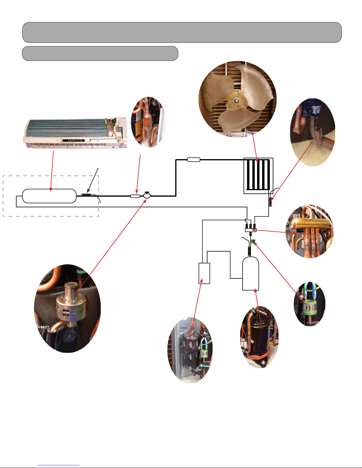
Product Introduction
Refrigeration Components
Indoor Unit
Temperature
Sensor
Heat Exchanger
Strainer
Outdoor Unit
Heat
Exchanger
Temperature
Sensor
Electronic Expansion
Val v e
Accumulator
Note:
Component locations may vary depending on models.
Compressor
Inverter
Compressor
4-way
High
Pressure
Switch
11
Cooling Mode
Cooling Mode
Product Introduction
Outdoor Unit
Strainer
Indoor Unit
Temperature
Sensor
Heat Exchanger
Note:
Please refer to actual model for exact piping
arrangement, refrigeration components may
vary.
Strainer
Electronic
expansion
valve
Accumulator not
Exchanger
on all sizes
Heat
Compressor
Inverter
4-way
4-way
valve
valve
Discharge
Silencer
Discharge
Temperature
Sensor
Note: The manufacturer reserves the right to modify the design and/or change the specications without notice. Please
refer to specic installation manual for current information.
12

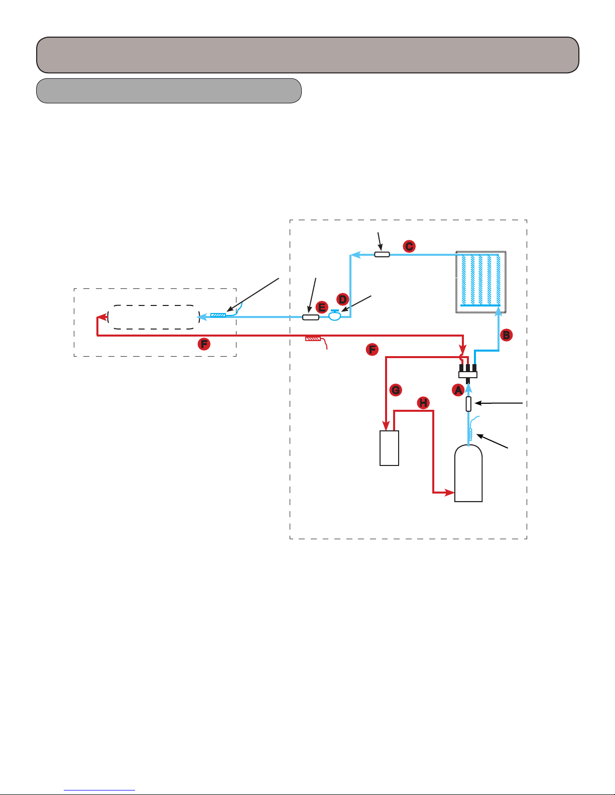
Product Introduction
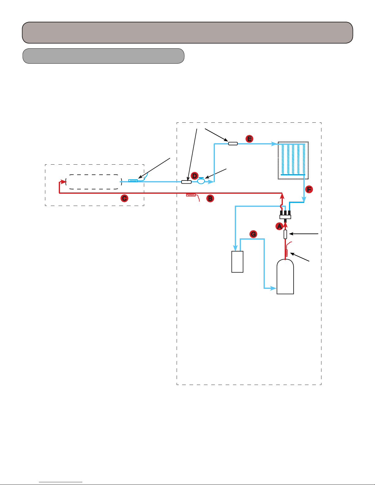
Cooling Mode
A. Hot gas is discharged from the compressor. e temperature of the gas is monitored by the Discharge
Temperature sensor and sent to the outdoor control panel.
B. e hot gas is directed through the 4-way valve, then enters the outdoor coil. e hot gas will be slightly
subcooled, however there are no pressure ports to take measurements.
C. e subcooled liquid will enter the lter to remove contaminates.
D. e subcooled liquid will enter the Electronic Expansion Valve (EEV) and will regulate to about a 10 degree
superheat level. e EEV will adjust its ow based upon the temperature
sensor readings. e adjustment process and compressor speed are controlled by the outdoor circuit board.
E. e refrigerant leaving the EEV will be in a low pressure/temperature saturated state. is cold saturated
refrigerant will move through the coil absorbing heat. is liquid will ash to a vapor and will be superheated
to about 10 degrees F. Since this tubing is cold, it must be insulated.
F. e superheated vapor will be returned to the outdoor unit’s 4-way valve.
G. e refrigerant will ow to the accumulator (not all models will have an accumulator) where liquid and vapor
are separated.
H. e refrigerant will ow to the compressor and complete another refrigeration cycle.
e control board will monitor the temperature and pressures and adjust the frequency of the compressor and
ow rate of the EEV as needed. ere are no pressure charts to evaluate temperature or pressures.
13
Heating Mode
Product Introduction
Outdoor Unit
Filter
Indoor Unit
Temperature
Sensor
Heat Exchanger
Note:
Please refer to actual model for exact piping
arrangement, refrigeration components may
vary.
Electronic
expansion
valve
Accumulator not
Exchanger
on all sizes
Heat
Compressor
Inverter
4-way
4-way
valve
valve
Discharge
Silencer
Discharge
Temperature
Sensor
Note: The manufacturer reserves the right to modify the design and/or change the specications without notice. Please
refer to specic installation manual for current information.
14

Product Introduction
Heating Mode
A. Hot gas is discharged from the compressor. e temperature of the gas in monitored by the Discharge
Temperature sensor and sent to the outdoor control panel.
B. e hot gas is directed through the 4-way valve to the appropriate indoor coil making the line a hot gas line.
C. e hot gas will enter the indoor coil and condense to a saturated mix as it travel through the coil and will be
slightly subcooled.
D. e refrigerant returns to the outdoor unit through the lter, then through the EEV reducing the refrigerant
to a low pressure liquid and will maintain 10 degrees F of superheat.
E. e cold refrigerant will travel through the outdoor coil (evaporator) and will pickup heat from the outdoor
air. is will cause the cold saturated refrigerant to ash to a saturated mixture which will be superheated to
10 degrees F.
F. e superheated vapor will travel through the 4-way valve to the accumulator which will prevent liquid
oodback.
G. e superheated gas will enter the compressor for another refrigeration cycle.
e control board will monitor the temperature and pressures and adjust the frequency of the compressor and
ow rate of the EEV as needed. ere are no pressure charts to evaluate temperature or pressures.
15
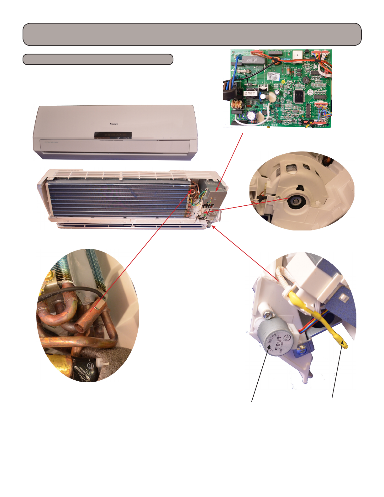
Product Introduction
Indoor Unit Components
Neo 12,000 btuh model
Other Neo models may very slightly.
Indoor Circuit
Board
Indoor Tube ermistor
Swing Motor
Fan Motor
Ambient
Temperature
Sensor
16
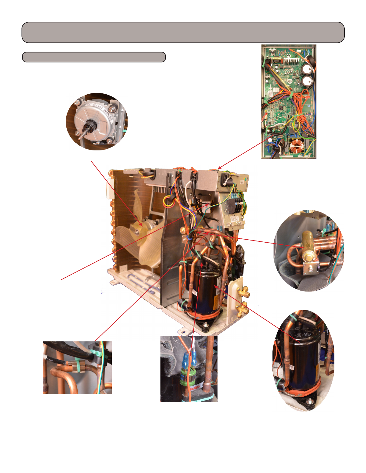
Product Introduction
Outdoor Unit Components
Neo 12,000 btuh Outdoor Unit
Other Neo models may very slightly.
Outdoor Fan
AP1 Board
Reactor
Exhaust Temp
Sensor
High Pressure Switch
Note:
Component locations may vary depending on models.
4-Way Valve
Compressor
17
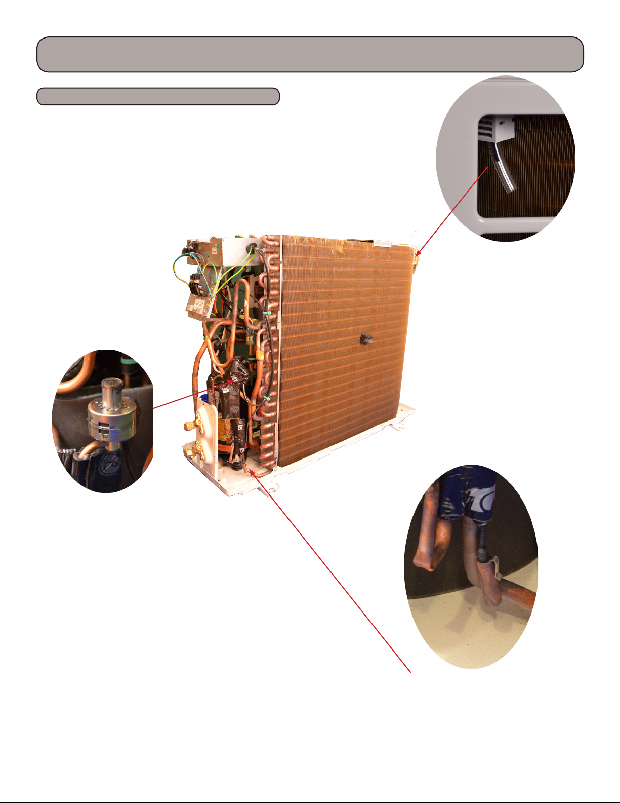
Product Introduction
Outdoor Unit Components
Outdoor Air
Sensor
Electronic Expansion
Val v e
18
Outdoor tube Sensor

Product Introduction
Basic Functions - 9K & 12K 115 volt
6.2 Brief Description of Modes and Functions
1.Temperature Parameters
Indoor preset temperature (Tpreset)
Indoor ambient temperature (Tamb.)
2.Basic Functions
Once the unit energized,the compressor shall never be restarted except 3mins interval at least.For the rst energization,if
the unit is at o status before power failure, the compressor can be restarted without 3-min delay. But if the unit is at ON
status before power failure, the compressor shall be restarted with 3mins delay. Once the compressor is started up, the compressor won’t stop running within 6mins with the change of room temperature.
(1)Cooling Mode
1. Under this mode, fan and swing function will be operating under setting mode, and temperature setting range is
61~86°F.
2. When outdoor unit is with malfunction or stop operation because of malfunction, indoor unit will keep its original operation status and display the malfunction.
3. When 0°F≤(setting temperature-ambient temperature)<3.6°F, if indoor fan speed is at high level, it will turn to medium
level (when compressor is operating); if indoor fan speed is at ultra high level, it will not turn to other fan speed; when
(ambient temperature-setting temperature)≥1.8°F, the fan speed will resume to setting value.
(2) Dry Mode
1. Under this mode, fan will operate as low fan speed and swing at setting status, temperature setting range is 61~86°F.
2. When outdoor unit is with malfunction or stop operation because of malfunction, indoor unit will keep its original operation status and display the malfunction.
(3) Heating Mode
1. Heating Conditions and Process
When the unit is powered on and is under heating mode, IDU will turn to anti cold wind function; when the unit is powered o and the indoor fan had ever turned on, the unit will turn to blowing residual heat.
2. When the compressor is running (doesn’t include entering each malfunction and protection):
a. When Toutdoor amblent≥68°F, if the indoor fan speed is low or medium, the fan speed will switch to high speed;if the
fan speed is high or turbo, the fan speed will not change.
b. When Toutdoor amblent≤64°F, the fan speed will turn back to set fan speed;
c. When 64°F<Toutdoor ambient<68°F, the unit will run in present fan speed (set fan speed or high fan speed); but if the
unit quits anti cold wind for the rst time in heating mode, the unit will run in set fan speed.
3.Defrosting
When there’s too much frost on outdoor condenser, the complete unit will enter into defrosting automatically to assure the
best heating eect. During defrosting process, the heating indicator is on for 10s and o for 0.5s.
4.Blow Residual Heat
When heating temperature reaches to the temperature point of stop operation, compressor and outdoor fan will stop operation. e horizontal louver rotates to the defaulted position in cooling mode. Indoor fan will stop operation aer operating at set fan speed for 60s. When the unit operates in heating or auto heating mode, compressor is started up and the unit
will stop operation aer indoor fan starts operation. Compressor and outdoor fan stop operation. e horizontal louver
will rotate to the position of breeze (defaulted position in cooling). e unit will stop operation aer indoor fan operates
at low fan speed for 10s. If the indoor fan stops due to blocking of PG motor, the louvers stop at the position when the unit
stops. (If the unit stops for other malfunction,the vertical louvers turn to cooling position 2) Indoor fan runs in set fan
speed for 60s and then stops.
19
Product Introduction
Basic Functions - 9K & 12K 115 volt
5.Cold Air Prevention
Aer the compressor starts, the indoor unit and louvers run in the mode below:
1. When Tindoor ambient<75°F: if Ttube≤104°F, the indoor fan doesn’t run and then the indoor fan runs in low fan speed
aer 2min. In 2min, if Ttube>104°F, the indoor fan will also run in low fan speed; aer running in low speed for 1min, the
indoor fan will turn to run in set fan speed. In 1 minute of low fan speed or in 2 minute that the indoor fan doesn’t run, if
Ttube>108°F, the indoor fan will turn to run in set fan speed.
2. When Tindoor ambient≥75°F: if Ttube≤108°F, the indoor fan runs in low fan speed and then the indoor fan runs in set
fan speed aer 1min. In 1min of running in low fan speed, if Ttube>108°F, the indoor fan will turn to run in set fan speed.
Note: Tindoor ambient in 1 and 2 means at the beginning of heating mode, the indoor ambient temperature before starting
up the compressor, or aer quitting defrosting, the indoor ambient temperature before clearing the defrosting symbol.
(4) Fan Mode
In fan mode, indoor fan operates at set fan speed, while compressor and outdoor fan all stop operation.
In fan mode, the temperature setting range is 61~86°F. Display is displaying operation icon and set temperature.
(5) Auto Mode
In auto mode, the system will select the operation mode (cooling, hearing of fan mode) according to the change of ambient temperature automatically. e display displays operation icon, actual operation mode and set temperature. 30s will be
delayed for protection during mode switchover. Protection function is the same as that in other modes.
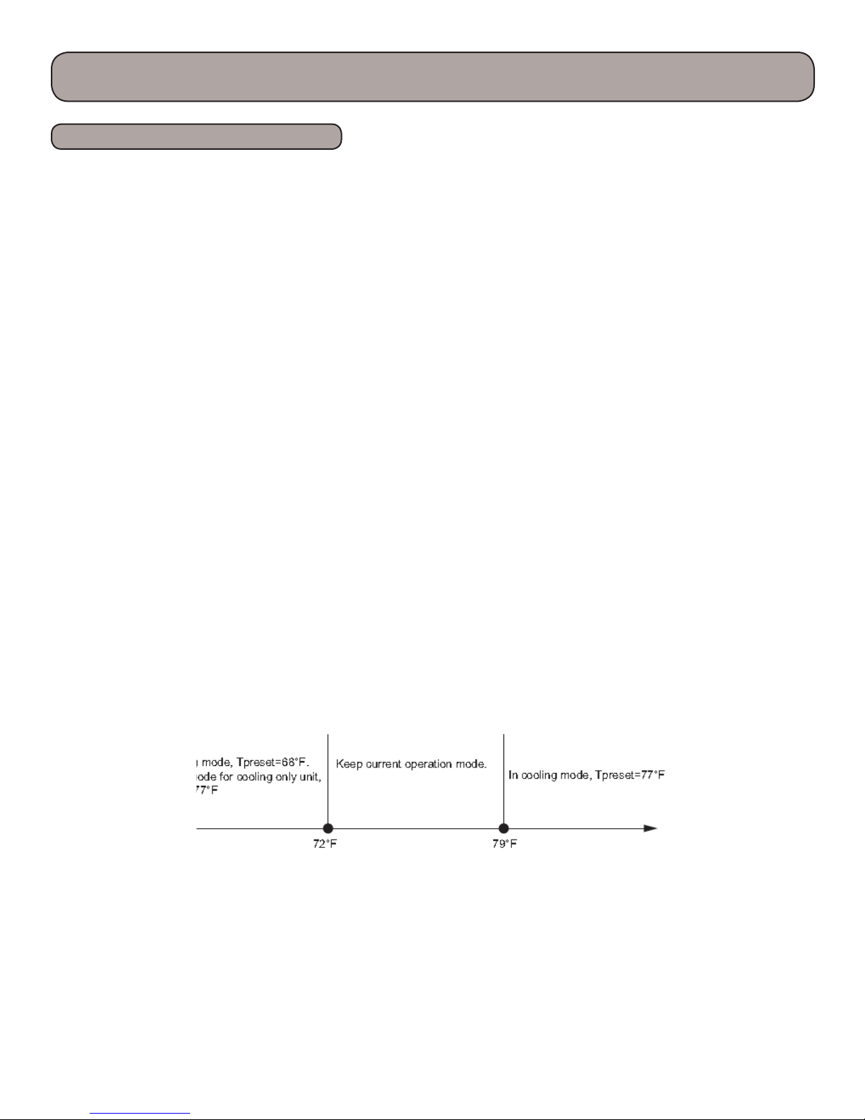
e selection method for auto operation mode in details is as below:
a. When Tamb. ≥79°F, the unit operates in cooling mode. e defaulted set temperature is 77°F;
b. When Tamb. ≤72°F, the unit operates in heating mode. e defaulted set temperature is 68°F (if it’s the cooling only unit
that operates in fan mode, the defaulted set temperature is 77°F);
c. When 73°F≤Tamb. ≤77°F,if the unit is turned on for the rst time,it will operate in auto fan mode;if the unit switched to
auto mode from other mode, it will keep previous operation mode; if the unit is switched to auto mode from dry mode, it
will operates in fan mode.
d. When the unit operates in auto mode, frequency of compressor during cooling and heating is same as that in cooling
mode and heating mode respectively.
Protection function:
a. It’s the same as that in cooling mode when it operates in cooling;
b.It’s the same as that in heating ode when it operates in heating;
3. Other Control
(1) Timer Function
General timer and clock timer functions are compatible by equipping remote controller with dierent functions.
1. General Timer
Timer ON can be set at unit OFF. If selected ON time is reached, the unit will start to operate according to previous setting status.Time setting range is 0.5-24hr in 30-minute increments. Timer OFF can be set at unit ON. If
selected OFF time is reached, the unit will stop operation. Time setting range is 0.5-24hr in 30-minute
increments.
20

Product Introduction
Basic Functions - 9K & 12K 115 volt
2. Clock Timer (it’s optional for the remote controller with clock timer)
Timer ON
If timer ON is set during operation of the unit, the unit will continue to operate. If timer ON is set at unit OFF, upon
ON time reaches the unit will start to operate according to previous setting status.
Timer OFF
If timer OFF is set at unit OFF, the system will keep standby status. If timer OFF is set at unit ON, upon OFF time
reaches the unit will stop operation.
Timer Change
Although timer has been set, the unit still can be turned on/o by pressing ON/OFF button of the remote controller.
You can also set the timer once again, and then the unit will operate according to the last setting.
If timer ON and timer OFF are set at the same time during operation of the unit, the unit will keep operating at current status till OFF time reaches.
If timer ON and timer OFF are set at the same time at unit OFF, the unit will keep o status till ON time reaches.
Each day in future, the system will operate according to preset mode till OFF time reaches and stop operation till ON
time reaches. If ON time and OFF time are the same, OFF command takes the priority.
time and OFF time are the same, OFF command takes the priority.
(2) Auto Button
If this button is pressed, the unit will operate in AUTO mode and indoor fan will operate at auto speed; meanwhile,
the swing motor operates.
Press this button again to turn o the unit.
(3) Buzzer
Upon energization or availably operating the unit or remote controller, the buzzer will give out a beep.
(4) Sleep Function
1. Cooling mode:
1.1 When initial ial set temperature range is 61~73°F, if turning on sleep function, temperature will increase 1.8°F for
every hour. Aer 5.4°F has been increased, the temperature will not change. 7 hours later, temperature will decrease
1.8°F. Aer that, the unit will keep operating at that temperature.
1.2 When initial set temperature range is 75~81°F, if turning on sleep function, temperature will increase 1.8°F for
every hour. Aer 3.6°F has been increased, the temperature will not change. 7 hours later, temperature will decrease
1.8°F. Aer that, the unit will keep operating at that temperature.
1.3 When initial set temperature range is 82~84°F, if turning on sleep function, temperature will increase 1.8°F for
every hour. Aer 1.8°F has been increased, the temperature will not change. 7 hours later, temperature will decrease
1.8°F. Aer that, the unit will keep operating at that temperature. 1.4 When initial set temperature is 86°F, the unit
will operate at that temperature. 7 hours later, temperature will decrease 1.8°F. Aer that, the unit will keep oper-
ating at that temperature.
2. Heating mode:
2.1 When initial set temperature is 61°F, the unit will operate at that temperature;
2.2 When initial set temperature range is 63~68°F, if turning on sleep function, temperature will decrease 1.8°F for
every hour. Aer 1.8°F has been decreased, the temperature will not change.
2.3 When initial set temperature range is 70~81°F, if turning on sleep function, temperature will decrease 1.8°F for
every hour. Aer 3.6°F has been decreased, the temperature will not change. 2.4 When initial set temperature range is
82~86°F, if turning on sleep function, temperature will decrease 1.8°F for every hour. Aer 5.4°F has been decreased,
the temperature will not change.
(5) Turbo Function
is function can be set in cooling or heating mode to quickly cool or heat the room.
21
Product Introduction
Basic Functions - 9K & 12K 115 volt
(6) X-fan Function
1. X-fan function can be set in cooling or drying mode (X-fan function is unavailable in auto, heating or fan mode).
When X-fan is ON, aer
pressing ON/OFF button to turn o the unit, indoor unit will run in low fan speed for 2min(in 2min, the horizontal
louver is in the minimum angel of swinging, other loads are o). When X-fan is OFF, press ON/OFF button to turn o
the complete unit.
2. During X-fan operation, aer pressing X-fan button, indoor fan stops operates immediately. Horizontal louver will
close and cold plasma and electrostatic dedusting is OFF as well.
(7) Control of Indoor Fan
e fan speed of indoor fan can be set in turbo, high, medium, low by remote controller.
It can also set at auto fan speed. When indoor fan operates in auto fan speed mode, the indoor fan will operate at high
speed,medium speed, low speed or turbo according to the change of ambient temperature.
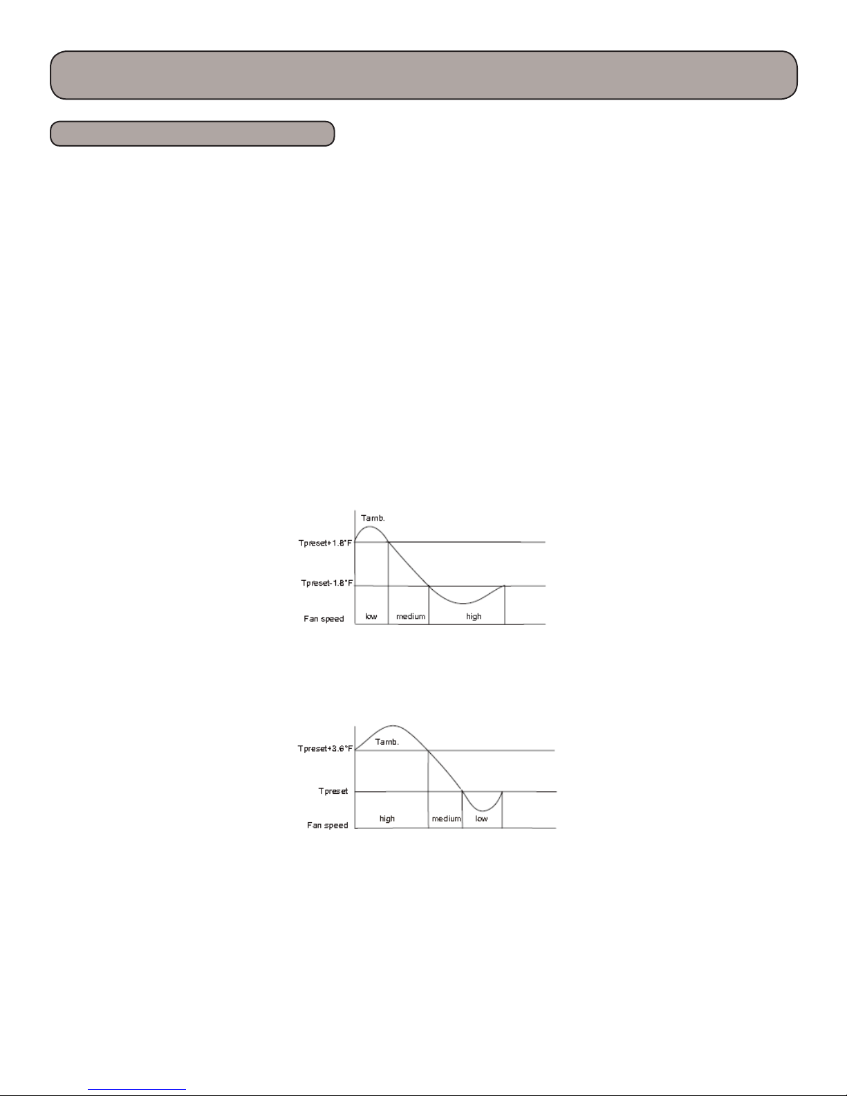
3. In auto heating mode or normal heating mode, the auto fan speed operates according to below mode:
When Tamb.<Tpreset-1.8°F, indoor fan operates at high speed;
When Tpreset-1.8°F<Tamb.<Tpreset+1.8°F, indoor fan operates at medium speed;
When Tamb.>Tpreset+1.8°F, indoor fan operates at low speed. Control drawing of auto fan in heating mode:
2. Fan mode, cooling mode: In auto cooling mode or normal cooling mode, auto fan speed operates according to
below mode:
3. Auto fan speed is not available in drying mode
Note: high speed, medium speed and low speed is to “notch 5”, “notch “3” and “notch 1” respectively.
As for the switchover among high speed, medium speed and low speed, the unit should operates at every speed for
3minutes and 3s at least.
22
Product Introduction
Basic Functions - 9K & 12K 115 volt
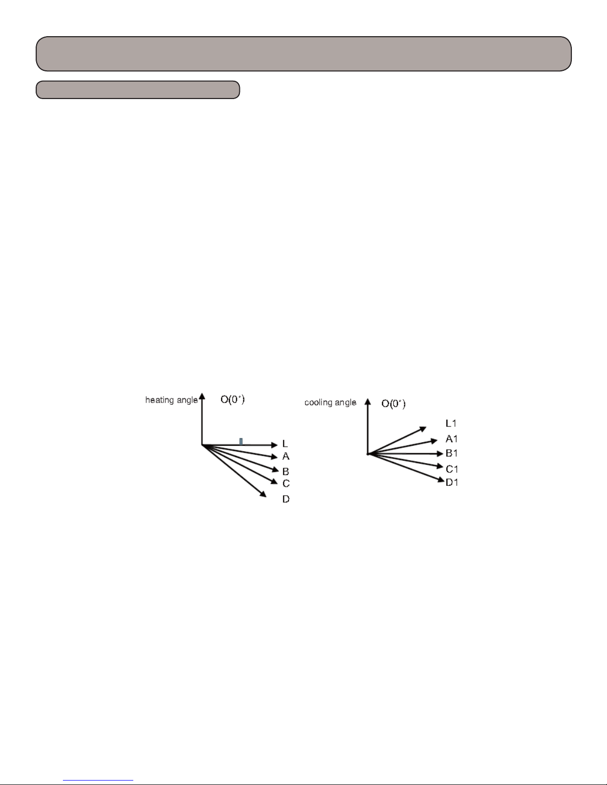
(8) Up and Down Swing Function
Aer turning on the unit, the louver will operate in the below angel. (if the remote controller is pressed
continuously within 2 seconds, the last signal will be executed, the previous signals will be invalid)
Aer energizing, the up and down swing motor will rstly rotate the louver to position 0 anticlockwise
(close in 138°) and close the air outlet. Aer turning on the unit, if swing function has been set, the louver will rotate to
position D clockwise in heating mode and auto heating mode; the louver will rotate to horizontal position L1 clockwise in
other modes. e indoor fan and compressor will be energized aer the louver opens to position L1. If set the swing function while turning on the unit, the louver will swing between L1 and D. e louver will close to position L when turning o
the unit.
(9) Display
1. Upon energization within 2s, the unit will display all icons. Under standby state, running indicating mark
is displayed. If the unit is started by remote controller, running indicating mark gives o light; meanwhile, the
mark of current running mode will be di played. If the light button is turned o, no mark will be displayed.
2. In defrosting, the heating indicator is on for 10s and o for 0.5s. In X-fan mode, the cooling indicator is on for
0.5s and o for 10s.
3. In auto mode, the nixie tube displays 25 in cooling and fan, and displays 20 in heating.
4. e nixie tube displays set temperature.
5. When there is a malfunction or protection, if timer o is set, this function will be executed.
(10) Memory Function
Memorized items: mode, up & down swing, light, set temperature and set fan speed.
When power is recovered aer power failure, the unit will automatically start operation according to memorized
status. Aer power recovery, the unit without timer setting before power failure will operate according to the last
setting; the unit with general timer setting which has not been fullled before power failure will memorize the
timer setting and re-calculate the time aer power recovery. If there is timer function in the last remote controller command but setting time has reached, the system will act as timer on/o setting before power failure. Aer
power failure, the system memorizes the operation states before power failure without timer action. Clock timer
can not be memorized.
(10) Memory Function
Memorized items: mode, up & down swing, light, set temperature and set fan speed.
When power is recovered aer power failure, the unit will automatically start operation according to memorized status.
Aer power recovery, the unit without timer setting before power failure will operate according to the last setting; the unit
with general timer setting which has not been fullled before power failure will memorize the timer setting and re-calculate the time aer power recovery. If there is timer function in the last remote controller command but setting time has
reached, the system will act as timer on/o setting before power failure. Aer power failure, the system memorizes the
operation states before power failure without timer action. Clock timer can not be memorized.
23

Product Introduction
Basic Functions - 9K & 12K 115 volt
(11) I FEEL Function(reserved)
When I FEEL command is received and controller has received the ambient temperature sent by remote controller, the
controller will operate at the temperature sent by remote controller (For cold air prevention, the unit operates according to the ambient temperature sensed by the air conditioner). If it only received I FEEL command and hasn’t received
the valid ambient temperature, air conditioner will operate according to the ambient temperature sensed by itself. Remote controller will send the ambient temperature to controller every 10min. If controller hasn’t received the ambient
temperature sent by remote controller for 11min, air conditioner will operate according to the ambient
temperature sensed y itself. If I FEEl hasn’t been set, ambient temperature will adopt the temperature sensed by air
conditioner. Controller displays I FEEL ambient temperature 34°F~138°F.
(12) Health, Cold Plasma Function(reserved)
At ON status, press health button (if there isn’t health button on remote controller, health function is ON in default)
on remote controller can set health or cold plasma function. Health or cold plasma function can operate when it set
ON and indoor fan operates.
(13) Fahrenheit Display Function
Niexie tube displays current set temperature. If the remote control signal is Fahrenheit, the temperature will be display
by Fahrenheit. Set temperature range is 61~86°F. Under auto mode, nixie tube displays 77°F in cooling and fan, and
68°F in heating. Cooling only controller
only displays 77°F.
(14) Locked Protection to Indoor Fan
If the indoor fan motor keeps low rotation speed for a continuous period of time aer startup, the unit will stop operation and display“H6”.
(15) Compulsory Defrosting Function
When the outdoor environment is formidable, such as temperature is too low and humidity is too high, and there
is too much frost in outdoor unit which aect the heating eect, users can select compulsory defrosting function to
outdoor unit’s heating eect. on method:
When the unit is turned on in heating mode by remote controller and the set temperature is 61°F, press “+,-,+,-,+,-”
buttons for 5s successively, indoor unit will enter into compulsory defrosting setting and send the compulsory defrosting mode signal to outdoor unit and then outdoor unit will enter into compulsory defrosting mode.
24

Product Introduction
Le Intentionally Blank
25

Product Introduction
Basic Functions - 9K & 12K 230 volt
Indoor preset temperature (Tpreset)
Indoor ambient temperature (Tamb.)
2. Basic Functions
Once energized, in no case should the compressor be restarted within less than 3 minutes. In the situation that memory
functionis available, for the rst energization, if the compressor is at stop before de-energization, the compressor will be
started without a3-minute lag; if the compressor is in operation before de-energization, the compressor will be started
with a 3-minute lag; and oncestarted, the compressor will not be stopped within 6 minutes regardless of changes in room
temperature;
(1) Cooling Mode
1. Working conditions and process of cooling
When Tamb.≥Tpreset, the unit will enter cooling operation, in which case the indoor fan, the outdoor fan and the compressor will workand the indoor fan will run at preset speed.
When Tamb.=Tpreset-3.6°F, the compressor will run in 15Hz for continuous 15 minutes; if Tamb.=Tpreset-3.6°F is not
changed aer that, the compressor will stop to run;
When Tamb.≤Tpreset-5.4°F, the compressor will stop to run, the outdoor fan motor will stop to run aer 30 seconds and
the indoor fan motor will run at set fan speed;
When Tpreset-3.6°F < Tamb.< Tpreset, the unit will keep the previous running status.
Under this mode, the four-way valve will be de-energized and temperature can be set within a range from 61 to 86°F.
If the compressor is shut down for some reason, the indoor fan and the swing device will operate at original state.
2. Protection
Antifreeze protection
Under cooling and dehumidifying mode, 6 minutes aer the compressor is started:
If T evap≤35.6°F, the compressor will operate at reduced frequency.
If T evap≤30.2°F is detected for durative 3 minutes, the compressor will stop, and aer 30 seconds, the outdoor fan will
stop; and under cooling mode, the indoor fan and the swing motor will remain at the original state.
If T evap. ≥50°F and the compressor has remained at OFF for at least 3 minutes, the compressor will resume its original
operation state.
Total current up and frequency down protection
When total current Itotal≤6A, increase frequency is allowed; when total current Itotal≥7A, increasing frequency is prohibited; when total current Itotal≥8A, the unit operates by decreasing frequency. When total current Itotal≥9A, the compressor stops operation, and indoor fan will stop operation aer 30s.
(2) Dehumidifying Mode
1. Working conditions and process of dehumidifying
If Tamb>Tpreset, the unit will enter cooling and dehumidifying mode, in which case the compressor and the outdoor fan
will operate
and the indoor fan will run at low speed.
If Tpreset -3.6°F≤Tamb≤Tpreset, the compressor remains at its original operation state.
If Tamb.< Tpreset -3.6°F, the compressor will stop, the outdoor fan will stop with a time lag of 30s, and the indoor fan will
operate at
low speed.
2. Protection
Protection is the same as that under the cooling mode.
(3) Heating Mode
1. Working conditions and process of heating
1. If Tpreset-(Tindoor ambient- Tcompensatory) ≥1.8°F, the unit enters heating mode, in which case the compressor, the
outdoor fan and the 4-way valve will operate simultaneously;
2. If -3.6°F<Tpreset-(Tindoor ambient- Tcompensatory) <1.8°F, the unit will maintain its original operating status.
26

Product Introduction
Basic Functions - 9K & 12K 230 volt
3. If Tpreset-(Tindoor ambient- Tcompensatory) ≤-3.6°F, the compressor will stop and the outdoor fan will stop with a
time lag of 30s;
4. If turning o the unit when the unit is in heating mode or switching heating mode to another mode, the 4-way valve will
be powered o aer the compressor stops for 2min (the compressor has already started in heating mode).
5. If Toutdoor ambient>86°F, the compressor will stop and the outdoor fan will stop with a time lag of 30s
6. When the compressor has started, if switching cooling or dry mode to heating mode, the 4-way valve will be energized
with a time lag of 2-3min.
Note: Tcompensatory is determined by indoor unit and outdoor unit. If the indoor unit controls Tcompensatory,
Tcompensatory is determined by the data sent by indoor unit to outdoor unit; if the indoor unit doesn’t control
Tcompensatory, the outdoor unit will control Tcompensatory and the default data is 5.4°F. (there is instruction in the
communication protocol to describe if the Tcompensatory is controlled by indoor unit)
2. Condition and process of defrost
(1)When Toutdoor ambient≤41°F and the compressor has run for 3h, if Toutdoor tube<0°F is continuously detected for
1min, the unit will enter defrosting; [Note: the accumulated time is cleared if one of the below condition is met: Toutdoor
ambient>41°F, the compressor starts up aer switching to cooling or dry mode, when defrosting is nished; for other
situations besides above conditions, the accumulated time will not be cleared (including the unit stops when reaching the
temperature point, the unit stops for protection, switching to fan mode,etc.)]
(2) When duration of successive heating operation is more than 45 minutes, or accumulated heating time more than 90
minutes, and one of the following conditions is reached, the unit will enter the defrost mode aer 3 minutes:
a. Toutdoor ambient>41°F, Toutdoor tube≤28.4°F;
b. 28.4°F≤Toutdoor ambient<41°F, Toutdoor tube≤21.2°F;
c. 23°F≤Toutdoor ambient<28.4°F, Toutdoor tube≤17.6°F;
d. 14°F≤Toutdoor ambient<23°F, Toutdoor tube- Tcompensatory≤(Toutdoor ambient-5.4°F)
e. Toutdoor ambient<14°F, Toutdoor tube- Tcompensatory≤(Toutdoor ambient-5.4°F)
Aer energization, for the rst defrosting, Tcompensation=0°F; if it is not the rst time of defrosting, Tcompensation will
be determined by
Toutdoor pipe when quitting defrosting last time;
a. Toutdoor pipe >35.6°F, Tcompensation=0°F;
b. Toutdoor pipe ≤35.6°F, Tcompensation=5.4°F.
(3) During defrosting, if operation time for compressor doesn’t reach 3min, the defrosting will not be entered in the
subsequent 2 hours. At that time, compressor stops operation and in 30s later, the outdoor fan will stop operation; in
another 30s, 4-way valve will stop operation; in 30s later, compressor will increase its frequency for defrosting. When
defrosting lasts for 450s, or Toutdoor pipe ≥50°F, compressor will decrease its frequency. In 30s later, compressor will stop
operation; in another 30s, 4-way valve will be started up. In 60s later, compressor and outdoor fan will operate. Frequency
for defrosting is 85Hz.
3. Protection
Cold air prevention
e unit is started under heating mode (the compressor is ON):
1. In the case of T indoor amb. <75.2°F: if T tube≤104°F and the indoor fan is at stop state, the indoor fan will begin to run
at low speed with a time lag of 2 minutes. Within 2 minutes, if T tube>104°F, the indoor fan also will run at low speed; and
aer 1-minute operation at low speed, the indoor fan will be converted to operation at preset speed. Within 1-minute low
speed operation or 2-minute nonoperation, if T tube>107.6°F, the fan will run at present speed.
2. In the case of T indoor amb. ≥75.2°F: if T tube≤107.6°F, the indoor fan will run at low speed, and aer one minute, the
indoor fan will be converted to preset speed. Within one-minute low speed operation, if T tube>107.6°F, the indoor fan
will be converted to preset speed.
Note: T indoor amb. indicated in1 and 2 refers to, under initially heating mode, the indoor ambient temperature before the
command to start the compressor is performed according to the program, or aer the unit is withdrawn from defrost, the
indoor ambient temperature before the defrost symbol is cleared.
27

Product Introduction
Basic Functions - 9K & 12K 230 volt
Total current up and frequency down protection
When total current Itotal≤6A, increase frequency is allowed; when total current Itotal≥7A, increasing frequency is
prohibited; when total current Itotal≥8A, the unit operates by decreasing frequency. When total current Itotal≥9A, the
compressor stops operation, and indoor fan will stop operation aer 30s.
(4) Fan Mode
Under the mode, the indoor fan will run at preset speed and the compressor, the outdoor fan, the four-way valve and
the electric heater will stop. Under the mode, temperature can be set within a range of 61 - 86°F.
(5) AUTO Mode
1. Working conditions and process of AUTO mode
a. When T ambient ≥78.8°F, the unit will operate in Cool mode. e set temperature is 77°F.
b. When T ambient ≤71.6°F, the heat pump unit will operate in Heat mode., set temperature be 68°F; the cooling only
unit will operate in Fan mode, set temperature be 77°F.
c. When 73.4°F≤T ambient ≤77°F, the unit will operate in the previous state. If it is energized for the rst time, it will
operate in Fan mode.
d. Under auto mode, if it’s cooling mode, operation frequency is same as that under cooling mode; if it’s heating mode,
operation frequency is same as that under heating mode.
2. Protection
a. In cooling operation, protection is the same as that under the cooling mode;
b. In heating operation, protection is the same as that under the heating mode;
c. When ambient temperature changes, operation mode will be converted preferentially. Once started, the compressor
will remain unchanged for at least 6 minutes.
(6) Common Protection Functions and Fault Display under COOL, HEAT, DRY and AUTO Modes
1.Overload protection
T tube: measured temperature of outdoor heat exchanger under cooling mode; and measured temperature of indoor
heat exchanger under heating mode.
1) Cooling overload
a. If T tube≤125.6°F, the unit will return to its original operation state.
b. If T tube≥131°F, frequency rise is not allowed.
c. If T tube≥136.4°F, the compressor will run at reduced frequency.
d. If T tube≥143.6°F, the compressor will stop and the indoor fan will run at preset speed.
2) Heating overload
a. If T tube≤122°F, the unit will return to its original operation state.
b. If T tube≥127.4°F, frequency rise is not allowed.
c. If T tube≥132.8°F, the compressor will run at reduced frequency.
d. If T tube≥140°F, the compressor will stop and the indoor fan will blow residue heat and then stop.
2. Exhaust temperature protection of compressor
If exhaust temperature ≥208.4°F, frequency is not allowed to rise.
If exhaust temperature ≥217.4°F, the compressor will run at reduced frequency.
If exhaust temperature ≥230°F, the compressor will stop.
If exhaust temperature ≤194°F and the compressor has stayed at stop for at least 3 minutes, the compressor will
resume its operation.
3. Communication fault
If the unit fails to receive correct signals for durative 3 minutes, communication fault can be justied and the whole
system will stop.
4. Module protection
Under module protection mode, the compressor will stop. When the compressor remains at stop for at least 3 minutes,
the compressor will resume its operation. If module protection occurs six times in succession, the compressor will not
be started again.
28

Product Introduction
Basic Functions - 9K & 12K 230 volt
5. Overload protection
If temperature sensed by the overload sensor is over 239°F, the compressor will stop and the outdoor fan will stop with a
time lag of 30 seconds. If temperature is below 203°F, the overload protection will be relieved.
6. DC bus voltage protection
If voltage on the DC bus is below 150V or over 420V, the compressor will stop and the outdoor fan will stop with a time lag
of 30 seconds. When voltage on the DC bus returns to its normal value and the compressor has stayed at stop for at least 3
minutes, the compressor will resume its operation.
3. Other Controls
(1) ON/OFF
Press the remote button ON/OFF: the on-o state will be changed once each time you press the button.
(2) Mode Selection
Press the remote button MODE, then select and show in the following ways: AUTO, COOL, DRY, FAN, HEAT,
AUTO.
(3) Temperature Setting Option Button
Each time you press the remote button TEMP+ or TEMP-, the setting temperature will be up or down by 1.8°F.
Regulating Range: 61 - 86°F,
the button is useless under the AUTO mode.
(4) Time Switch
You should start and stop the machine according to the setting time by remote control.
(5) SLEEP function
Sleep mode is only valid under cooling mode and heating mode;
Cooling mode: Basing on the set temperature of remote controller, aer turning on the sleep function for a few
hours, set temperature will increase properly and automatically according to human body’s comfort.
Heating mode: Basing on the set temperature of remote controller, aer turning on the sleep function for a few
hours, set temperature will decrease properly and automatically according to human body’s comfort.
(6) Indoor Fan Control
e Indoor Fan can be set as HIGH, MED, LOW by remote control, and the Indoor Fan will be respectively run
at high, medium, low speed. It will also be set as AUTO, and the Indoor Fan is as the followings at the automatic
wind speed.
Cooling mode:
T ring ≥ T setting + 3.6°F, high speed;
T setting - 3.6°F<T ring<T setting + 3.6°F, medium speed;
T ring≤ T setting - 3.6°F, low speed.
Sending wind mode:
T ring> T setting+ 7.2°F, high speed;
T setting +3.6°F≤T ring≤T setting + 7.2°F, medium speed;
T ring<T setting +3.6°F, low speed.
Moisture removal mode: force to be set as the low speed
Heating mode:
T ring≤ T setting + 1.8°F, high speed;
T setting +1.8°F<T ring<T setting + 9°F, medium speed;
T ring ≥T setting + 3.6°F, low speed.
29
Product Introduction
Basic Functions - 9K & 12K 230 volt
(7) Buzzer Control
e buzzer will send a “Di” sound when the air conditioner is powered up or received the information sent by the
remote control or there is a button input, the single tube cooler doesn’t receive the remote control ON signal under the
mode of heating mode.
(8) Auto button
If the controller is on, it will stop by pressing the button, and if the controller is o, it will be automatic running state
by pressing the button, swing on and light on, and the main unit will run based on the remote control if there is
remote control order.
(9) Up-and-Down Swinging Control
When power on, the up-and-down motor will rstly move the air deector to counter-clockwise, close the air outlet.
Aer starting the machine, if you don’t set the swinging function, heating mode and auto-heating mode, the up-anddown air deector will move to
D clockwise; under other modes, the up-and-down air deector will move to L1. If you set the swinging function
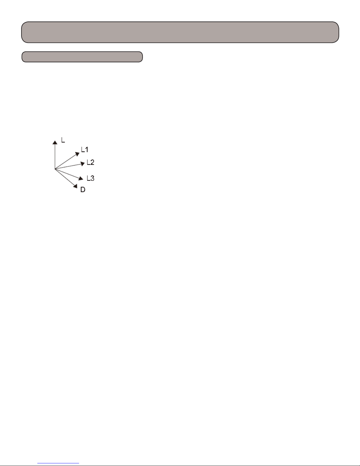
when you start the machine, then the wind blade will swing between L and D. e air deector has 7 swinging states:
Location L, Location A, Location
B, Location C, Location D, Location L to Location D, stop at any location between L-D (the included angle between
L~D is the same). e air deector will be closed at 0 Location, and the swinging is eectual only on condition that
setting the swinging order and the inner fan is running. e indoor fan and compressor may get the power when air
deector is on the default location.
(10) Display
1. Operation pattern and mode pattern display
All the display patterns will display for a time when the power on, the operation indication pattern will display in red
under standby status. When the machine is start by remote control, the indication pattern will light and display the
current operation mode (the mode light includes: Cooling, heating and dehumidify). If you close the light key, all the
display patterns will close.
2. Double-8 display
According to the dierent setting of remote control, the nixie light may display the current temperature (the
temperature scope is from 61 to 86°F) and indoor ambient temperature. e heating and air supply temperature will
display 77°F under auto-mode, the temperature will display 64.4°F, under the heating mode, heating indicator on
indoor unit will ON 10s and OFF 0.5s successively under the defrosting mode.(If you set the Fahrenheit temperature
display, the nixie light will display according to Fahrenheit temperature)
30
 Loading...