

Gree GWH28AAE-K3NNA1A, GWH28AAE-K3NNA2A, GWH28AAE-K3NNA1A/I, GWH28AAE-K3NNA2A/I, GWH28AAE-K3NNA1A/O Service Manual

GREE ELECTRIC APPLIANCES,INC.OF ZHUHAI
Change for Life
Service Manual
Models: GWH28AAE-K3NNA1A
GWH28AAE-K3NNA2A
(Refrigerant:R410A)

Table of Contents
Service Manual
Part
1. Summary
2. Specications
2.1 Specication Sheet ...........................................................................................................2
2.2 Capacity Curve in Different Outdoor Temperature ...........................................................4
2.3 Cooling and Heating Data Sheet in Rated Frequency .....................................................4
: Technical Information
Ⅰ
......................................................................................................................1
..........................................................................................................2
3. Outline Dimension Diagram
3.1 Indoor Unit ........................................................................................................................5
3.2 Outdoor Unit .....................................................................................................................5
4. Refrigerant System Diagram
5. Electrical Part
5.1 Wiring Diagram .................................................................................................................7
5.2 PCB Printed Diagram .......................................................................................................9
6. Function and Control
...........................................................................................................7
...................................................................................... 11
.......................................................................1
........................................................................5
......................................................................6
6.1 Remote Controller Introduction .....................................................................................11
6.2 Brief Description of Modes and Functions ......................................................................14
Part
: Installation and Maintenance
Ⅱ
7. Notes for Installation and Maintenance
8. Installation
8.1 Installation Dimension Diagram ......................................................................................22
8.2 Installation Parts-checking ............................................................................................24
8.3 Selection of Installation Location ....................................................................................24
8.4 Electric Connection Requirement ..................................................................................24
8.5 Installation of Indoor Unit ................................................................................................24
8.6 Installation of Outdoor Unit .............................................................................................27
8.7 Vacuum Pumping and Leak Detection ...........................................................................28
8.8 Check after Installation and Test Operation ...................................................................28
9. Maintenance
................................................................................................................22
............................................................................................................29
.................................................19
..........................................19
9.1 Error Code ......................................................................................................................29
9.2 Procedure of Troubleshooting ........................................................................................32
9.3 Maintenance Method for Normal Malfunction .................................................................43
Table of contents

Service Manual
10. Exploded View and Parts List
10.1 Indoor Unit ....................................................................................................................45
10.2 Outdoor Unit .................................................................................................................47
11. Removal Procedure
11.1 Removal Procedure of Indoor Unit ...............................................................................49
11.2 Removal Procedure of Outdoor Unit ............................................................................54
Appendix:
Appendix 1: Reference Sheet of Celsius and Fahrenheit ....................................................59
Appendix 2: Conguration of Connection Pipe .....................................................................59
Appendix 3: Pipe Expanding Method ...................................................................................60
Appendix 4: List of Resistance for Temperature Sensor ......................................................61
........................................................................................................................59
.......................................................................................49
..............................................................45
Service Manual
Part
Ⅰ
: Technical Information
1. Summary
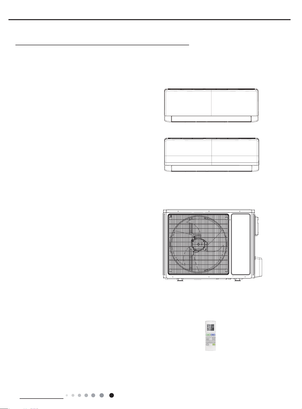
Indoor Unit:
GWH28AAE-K3NNA1A/I
GWH28AAE-K3NNA2A/I
Outdoor Unit:
GWH28AAE-K3NNA1A/O
Remote Controller:
YAW1F1
Technical Information
1
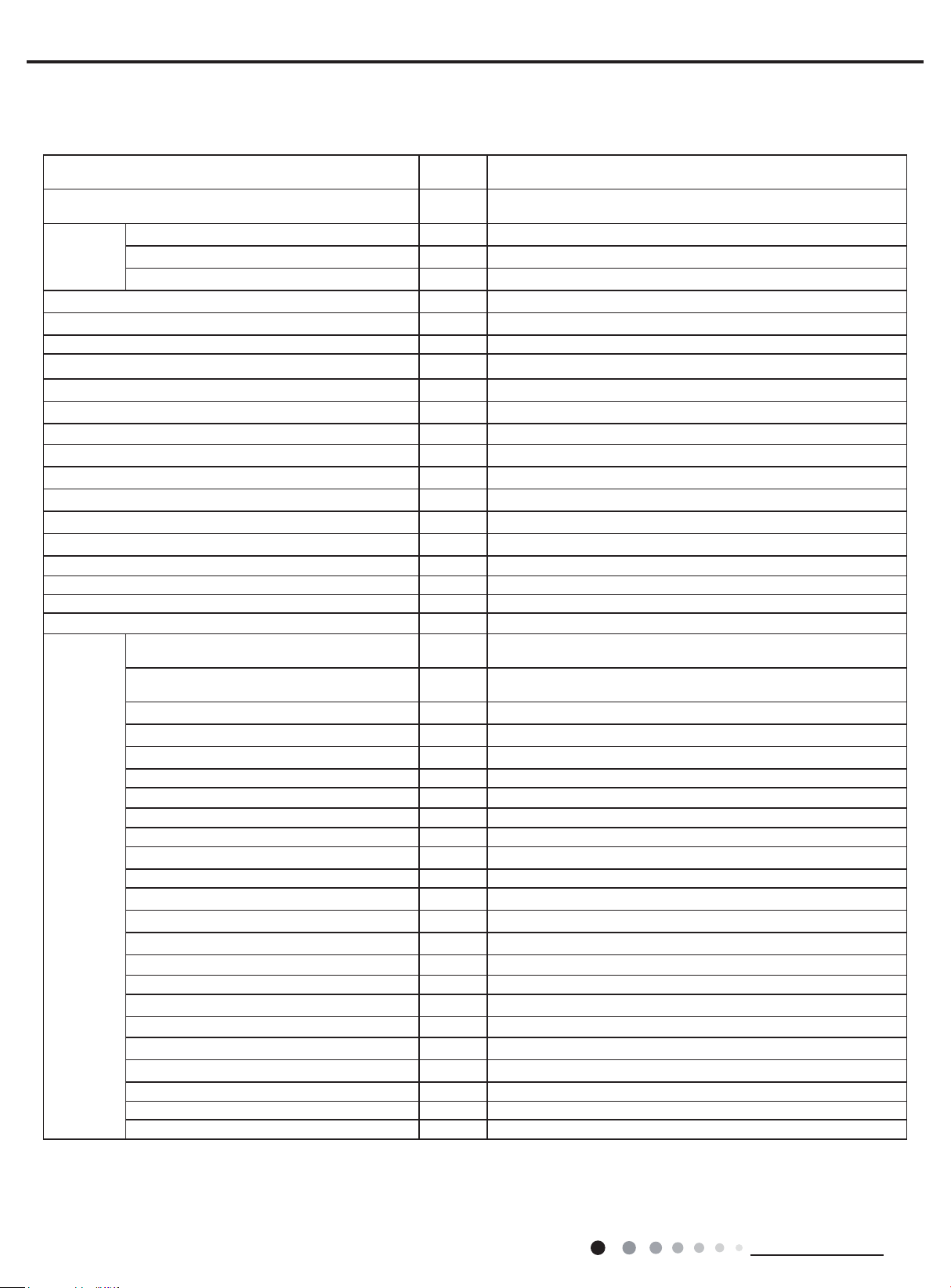
2. Specications
2.1 Specication Sheet
Service Manual
Model
Product Code
Power
Supply
Power Supply Mode Outdoor
Cooling Capacity W 8000
Heating Capacity W 8500
Cooling Power Input W 2846
Heating Power Input W 2647
Cooling Current Input A 12.3
Heating Current Input A 12
Rated Input W 3650
Rated Current A 20
Air Flow Volume(SH/H/M/L/SL) m3/h 1200/1100/1000/850/-
Dehumidifying Volume L/h 3.0
EER W/W 2.81
COP W/W 3.21
SEER W/W /
HSPF W/W /
Application Area m
Indoor Unit
Rated Voltage V~ 220-240
Rated Frequency Hz 50
Phases 1
2
Fan Type
Product Code of Indoor Unit
Fan Type Cross-ow
Diameter Length(DXL) mm Ф108X830
Fan Motor Cooling Speed(SH/H/M/L/SL) r/min 1330/1200/1000/900/-
Fan Motor Heating Speed(SH/H/M/L/SL) r/min 1330/1200/1000/900/-
Output of Fan Motor W 35
Fan Motor RLA A 0.35
Fan Motor Capacitor μF 3
Evaporator Form Aluminum Fin-copper Tube
Pipe Diameter mm Ф7
Row-n Gap mm 2.5-1.5
Coil Length (LXDXW) mm 845X25.4X342.9
Swing Motor Model MP35CP
Output of Swing Motor W 2.5
Fuse A 3.15
Sound Pressure Level (SH/H/M/L/SL) dB (A) 51/48/42/39/-
Sound Power Level (SH/H/M/L/SL) dB (A) 61/58/52/49/-
Dimension (WXHXD) mm 1080X325X245
Dimension of Carton Box (LXWXH) mm 1125X397X320
Dimension of Package (LXWXH) mm 1145X400X330
Net Weight kg 16.5
Gross Weight kg 19.5
GWH28AAE-K3NNA1A
GWH28AAE-K3NNA2A
CA476002101
CA477001301
46-70
GWH28AAE-K3NNA1A/I
GWH28AAE-K3NNA2A/I
CA476N02101
CA477N01301
2
Technical Information
Service Manual
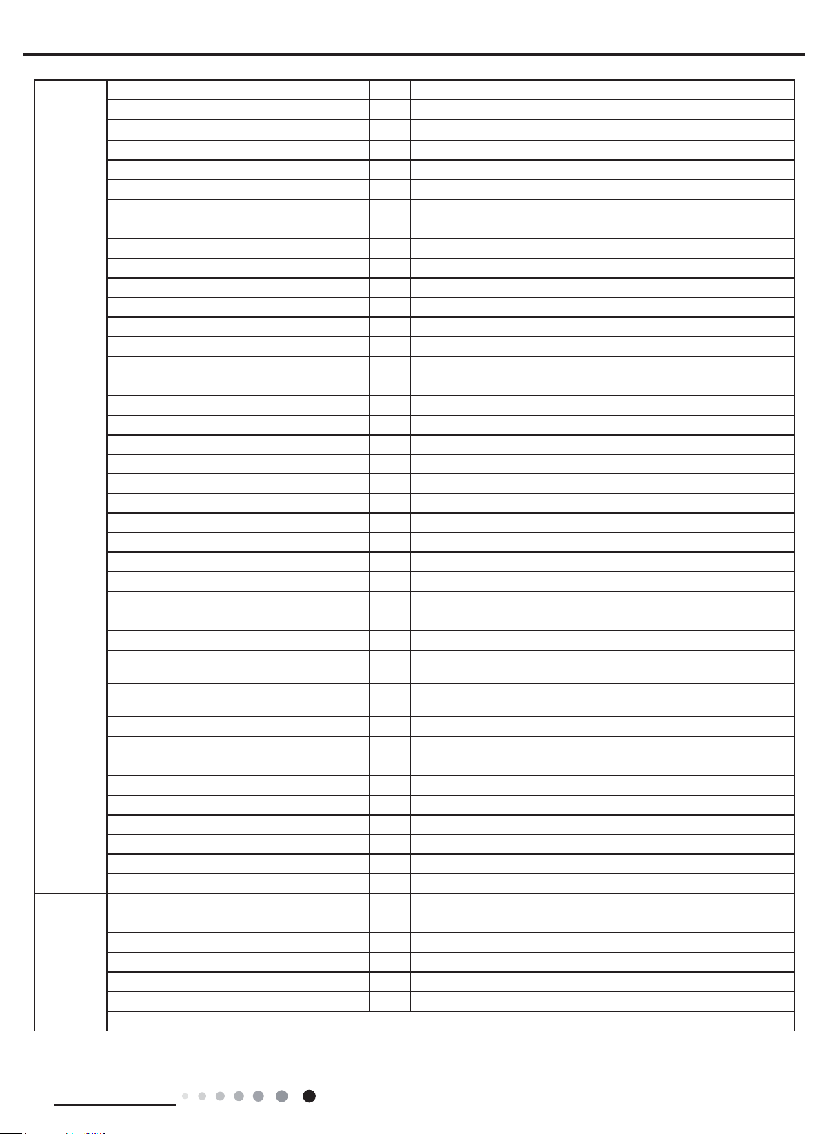
Outdoor Unit
Connection
Pipe
Model of Outdoor Unit GWH28AAE-K3NNA1A/O
Outdoor Unit Product Code CA476W02101
Compressor Manufacturer/Trademark ZHUHAI LANDA COMPRESSOR CO., LTD
Compressor Model QXAS-F305N450
Compressor Oil ATMOS-RB68EP or equivalent
Compressor Type Rotary
L.R.A. A 60
Compressor RLA A 11.6
Compressor Power Input W 2525
Overload Protector /
Throttling Method Capillary
Operation Temp
Ambient Temp (Cooling)
Ambient Temp (Heating)
o
C 16~30
o
C 18~43
o
C -7~24
Condenser Form Aluminum Fin-copper Tube
Pipe Diameter mm Ф7
Rows-n Gap mm 2.5-1.4
Coil Length (LXDXW) mm 820X38.1X660
Fan Motor Speed rpm 850
Output of Fan Motor W 35
Fan Motor RLA A 0.8
Fan Motor Capacitor μF 4.5
Air Flow Volume of Outdoor Unit m3/h 1800
Fan Type Axial-ow
Fan Diameter mm Ф520
Defrosting Method Automatic Defrosting
Climate Type T1
Isolation I
Moisture Protection IPX4
Permissible Excessive Operating Pressure for
the Discharge Side
Permissible Excessive Operating Pressure for
the Suction Side
MPa 4.3
MPa 2.5
Sound Pressure Level (H/M/L) dB (A) 59/-/-
Sound Power Level (H/M/L) dB (A) 69/-/-
Dimension (WXHXD) mm 965X700X396
Dimension of Carton Box (LXWXH) mm 1026X455X735
Dimension of Package (LXWXH) mm 1029X458X750
Net Weight kg 61
Gross Weight kg 65.5
Refrigerant R410A
Refrigerant Charge kg 1.9
Length m 5
Gas Additional Charge g/m 15
Outer Diameter Liquid Pipe mm Ф6
Outer Diameter Gas Pipe mm Ф16
Max Distance Height m 10
Max Distance Length m 30
Note: The connection pipe applies metric diameter.
The above data is subject to change without notice; please refer to the nameplate of the unit.
Technical Information
3
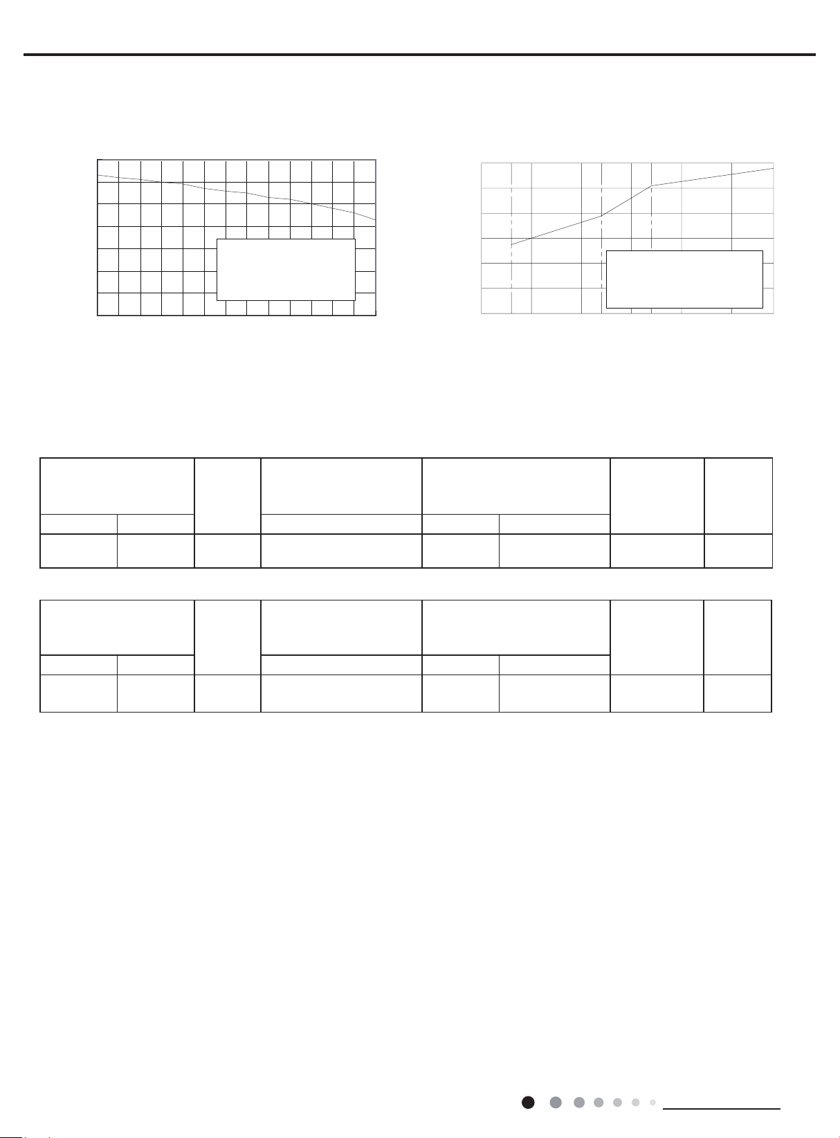
2.2 Capacity Curve in Different Outdoor Temperature
) % ( a p a c i t y r a t i o C
24
01
Cooling Heating
Service Manual
110
100
90
80
70
60
50
40
Condition
Indoor:DB27
Indoor air flow: Super High
Pipe length:5m
°C
WB19
°C
30 31 32 33 34 35 36 37 38 39 40 41 42 43
Outdoor temp.( ) Outdoor temp.( )
°C
120
100
80
60
40
20
0
-1 5
2.3 Cooling and Heating Data Sheet in Rated Frequency
Cooling:
Rated cooling condition(°C)
(DB/WB)
Indoor Outdoor P (MPa) T1 (°C) T2 (°C)
27/19 35/24 28K 0.9~1.1
Model
Pressure of gas pipe
connecting indoor and
outdoor unit
Inlet and outlet pipe temperature
of heat exchanger
in:6~8
out:10~12
in:75~85
out:37~43
Condition Heating
Indoor:DB20
Indoor air flow: Super High
Pipe length:5m
°C
0
157-7 -5 02
°C
Fan speed of
indoor unit
Super High High
Fan speed
of outdoor
unit
Heating:
Rated heating condition(°C)
(DB/WB)
Indoor Outdoor P (MPa) T1 (°C) T2 (°C)
20/- 7/6 28K 2.8~3.0
Instruction:
T1: Inlet and outlet pipe temperature of evaporator
T2: Inlet and outlet pipe temperature of condenser
P: Pressure at the side of big valve
Connection pipe length: 5 m.
Model
Pressure of gas pipe
connecting indoor and
outdoor unit
Inlet and outlet pipe temperature
in:75~85
out:37~43
of heat exchanger
in:1~3
out:2-5
Fan speed of
indoor unit
Super High High
Fan speed
of outdoor
unit
4
Technical Information
Service Manual
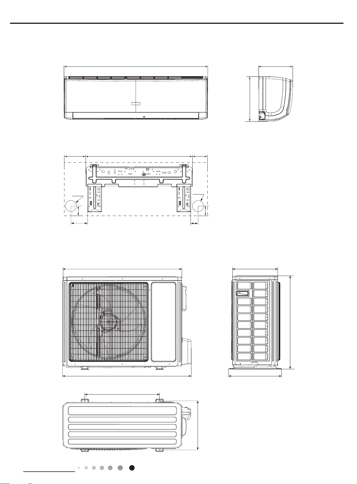
340
897
1080
245
3. Outline Dimension Diagram
3.1 Indoor Unit
207 685 188
324
Φ70
43
154
3.2 Outdoor Unit
79
Φ70
43
Unit:mm
700
Technical Information
965
560
396
364
Unit:mm
5
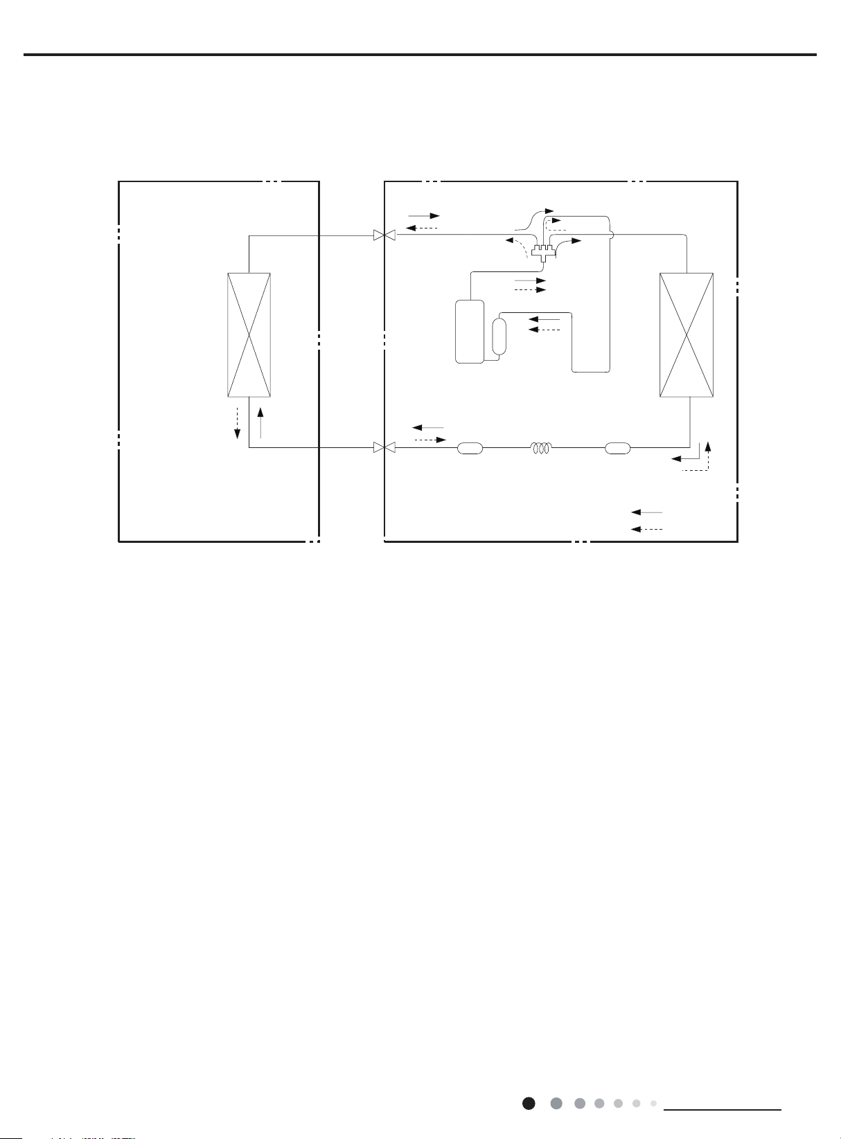
4. Refrigerant System Diagram
Indoor unit
Outdoor unit
Indoor unit
Outdoor unit
Accumlator
COOLING
Discharge
Suction
Heat
exchanger
(evaporator)
Heat
exchanger
(condenser)
Valve
Valve
Liquid pipe
side
Gas pipe
side
Compressor
Strainer
Capillary
Cooling and heating model
Gas pipe
side
Valve
Service Manual
4-Way valve
Heat
exchanger
(evaporator)
Connection pipe specication:
Liquid pipe:1/4" (6mm)
Gas pipe:5/8" (16mm)
Liquid pipe
side
Valve
Discharge
Suction
Compressor
Strainer StrainerCapillary
Accumlator
Heat
exchanger
(condenser)
COOLING
HEATING
6
Technical Information
Service Manual
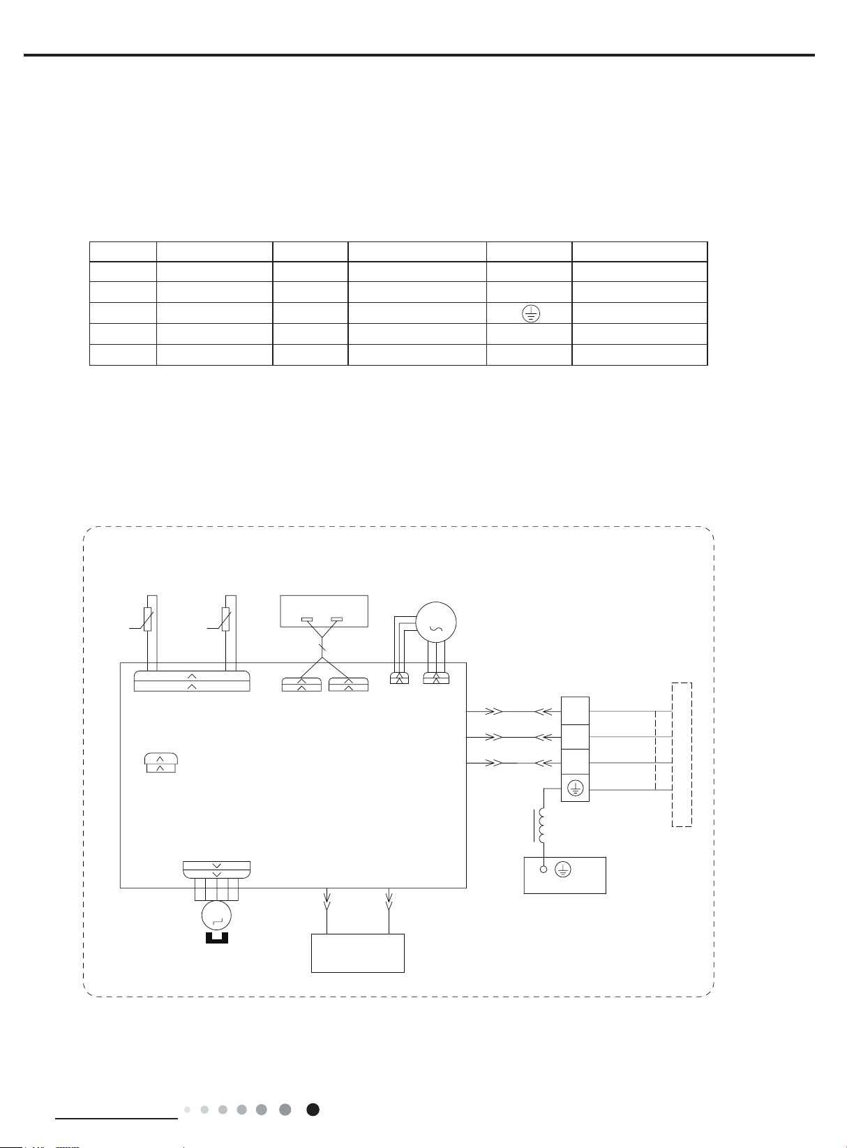
5. Electrical Part
5.1 Wiring Diagram
● Instruction
Symbol Symbol Color Symbol Symbol Color Symbol Name
WH White GN Green CAP Jumper cap
YE Yellow BN Brown COMP Compressor
RD Red BU Blue Grounding wire
YEGN Yellow/Green BK Black / /
VT Violet OG Orange / /
Note: Jumper cap is used to determine fan speed and the swing angle of horizontal lover for this model.
● Indoor Unit
78%(
6(1625
57
7(03
76(1625
&$3
-803
5220
6(1625
7(03
5(&(,9(5$1'
',63/$<%2$5'
$3
57
',63
$3
35,17('&,5&8,7%2$5'
6:,1*
6:,1*8'
+($/7+/
',63/$<
',63
)$102725
3*)
&20287
/$&/
+($/7+1
0
3*
1
%8
%.
%1
0$*1(7,&
5,1*
/
7(50,1$/
%/2&.
1
;7
<(*1
3(
(9$325$725
%8
%.
%1
<(*1
&211(&7,1*
&$%/(
287'22581,7
Technical Information
0
83'2:1
67(33,1*
02725
'58%
&2/'3/$60$
*(1(5$725
6363247703
7
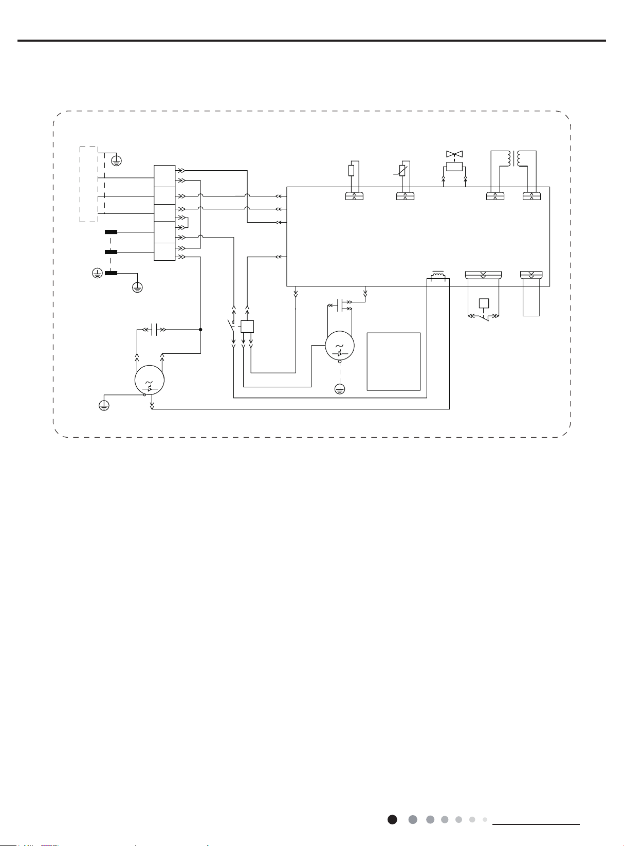
● Outdoor Unit
Service Manual
<(*1
3(
%8
%.
,1'22581,7
/
1
32:(5
%1
%1
%8
<(*1
<(
6 50
<(*1
3(
%.
3(
;7
1
7(50,1$/
%/2&.
3(
&$3
&
&203
&
/
1
&203
%8
%1
%8
7
%8
-
/ $
%8
%.
%8
%.
%1
%1
.0
5'
$
&20,11(5
$&/
1
&203
1
$&&217$&725
%8
%.
%8
6+,(/',1*
5(6,6725
5
2875220
28778%(
7(03
57
28778%(
6(1625
:$<9$/9(
<9
97
9 1
$335,17('&,5&8,7%2$5'
/
2)$1+
5'
)$1
02725
&$3
&
0
3(
<(*1
%1
%1
127(0RWRU
JURXQGRQO\
DSSOLHVWR
WKHLURQ
VKHOOPRWRU
3(
<( :+
+,*+35(6685(
6:,7&+
75$16)250(5
97
+33
600007000636
7&
+3
3
ėĖ
7528775,1
/33
%.
These wiring diagrams are subject to change without notice; please refer to the one supplied with the unit.
8
Technical Information
Service Manual
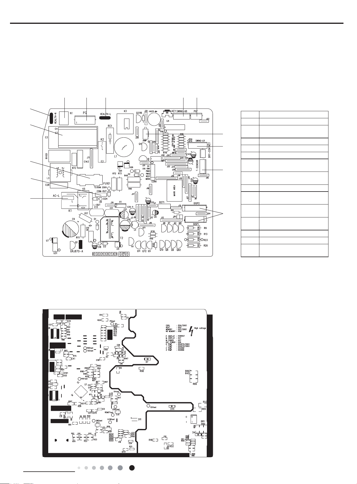
5.2 PCB Printed Diagram
Indoor Unit
● Top view
7 8
6
5
4
3
2
9 10
11
12
13
14
1
No. Name
Interface of display
1
Live wire interface of power
2
supply
3 Communication wire
4 Fuse
5 Indoor fan driven capacitor
Neutral wire interface of cold
6
plasma
Neutral wire interface of
7
power supply
8 Interface of indoor fan
Live wire interface of cold
9
plasma
Interface of up & down swing
10
motor
Interface of indoor fan
11
feedback
12 Jumper cap
13 Interface of left & right motor
Temperature sensor
14
interface
● Bottom view
Technical Information
9
12 34
10
11
12
13
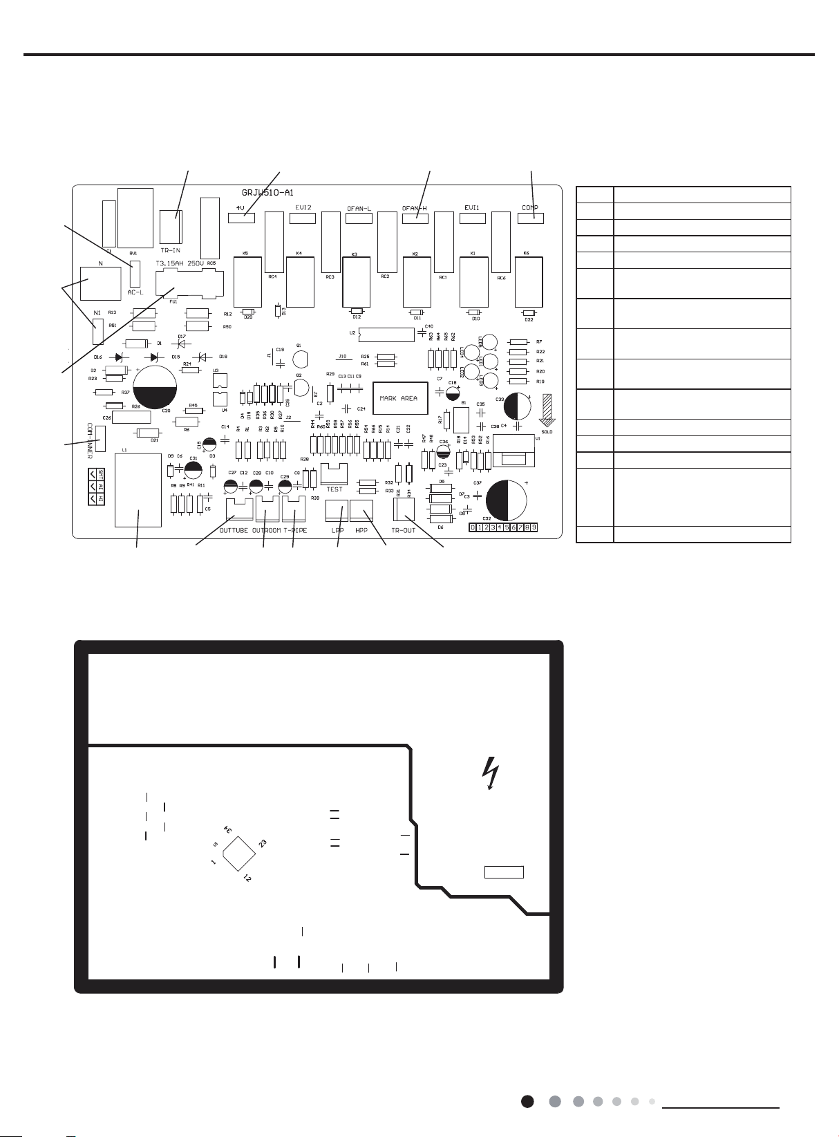
Outdoor Unit
● Top view
81415 9
7
6
5
Service Manual
1 Input of transformer
2 Terminal for 4-way valve
3 Terminal for outdoor fan
4 Terminal for compressor
5 Output of transformer
Terminal for high pressure
6
protection
Terminal for low pressure
7
protection
Terminal for outdoor ambient
8
temp sensor
Terminal for outdoor pipe temp
9
sensor
Terminal for communication
10
wire
11 Protective tube
12 Terminal for neutral wire
13 Terminal for live wire
Wiring terminal of outdoor
discharge temperature sensor
14
(Only for the models with this
function)
15 Current mutual-inductor
● Bottom view
10
Technical Information
Service Manual
Temp. display type
Sleep mode
do not. Please refer to the actual models.
6. Function and Control
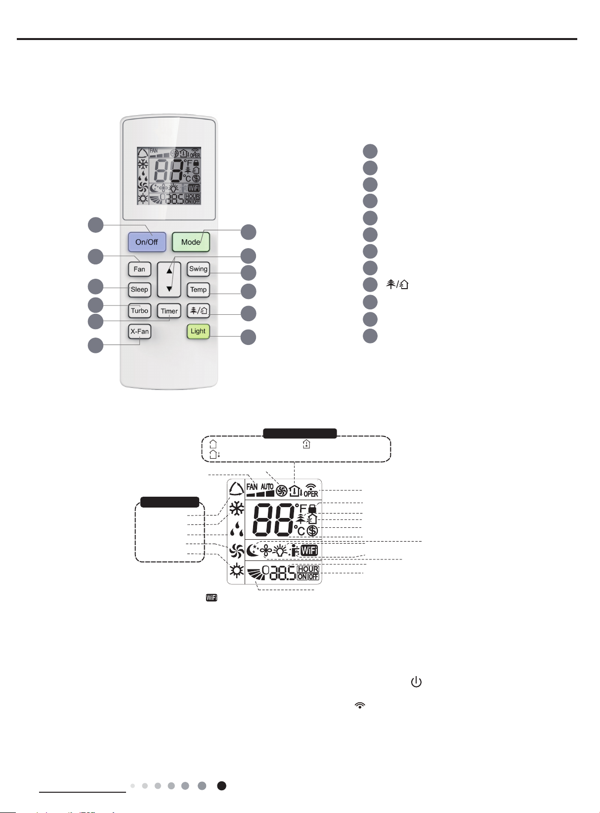
6.1 Remote Controller Introduction
1
3
6
8
10
11
2
4
5
7
9
12
1
On/Off button
2 Mode button
3 Fan button
4
5
6 Sleep button
7 Temp button
8 Turbo button
9
10 Timer button
11 X-Fan button
12 Light button
▲
▲/ button
Swing button
button
Introduction for icons on display screen
Set fan speed
Operation mode
Auto mode
Cool mode
Dry mode
Fan mode
Heat mode
NOTICE:
:Set temp.
:Outdoor ambient temp.
Turbo mode
“ ” This is a general remote controller. Some models have this function while some
:Indoor ambient temp.
Send signal
Child lock
health function
ventilation operation
8ć heating function
Set temperature
Light function
I feel function
Set time
TIMER ON /TIMER OFF
Up & down swing
X-fan mode
Introduction for buttons on remote controller
Note:
● This is a general use remote controller, it could be used for the air conditioners with multifunction; For some function, which the
model doesn't have, if press the corresponding button on the remote controller that the unit will keep the original running status.
● After putting through the power, the air conditioner will give out a sound. Operation indictor " " is ON (red indicator). After that,
you can operate the air conditioner by using remote controller.
●
Under on status, pressing the button on the remote controller, the signal icon " "
and the air conditioner will give out a “de” sound, which means the signal has been sent to the air conditioner.
Under off status, set temperature and clock icon will be displayed on the display of remote controller (If timer on, timer off and light
functions are set, the corresponding icons will be displayed on the display of remote controller at the same ime); Under on status, the
display will show the corresponding set function icons.
on the display of remote controller will blink once
Technical Information
11
Service Manual
A
*
1. On/Off button
Press this button to turn on the unit. Press this button again to turn off the unit.
2. Mode button
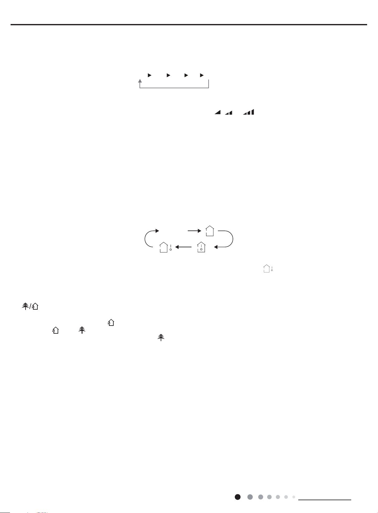
Each time you press this button,a mode is selected in a sequence that goes from AUTO, COOL, DRY, FAN, and HEAT *, as the following:
UTOCOOL DRY FAN
HEAT
Note: Only for models with heating function.
3. Fan button
This button is used for setting Fan Speed in the sequence that goes from AUTO, , , to , then back to Auto.
4. ▲/▲ button
● Press ▲ / button to increase/decreaseset temperature. In AUTO mode, set temperature is not adjustable.
● When setting Timer On or Timer Off, press "▲" or " " button to adjust the time.
▲
▲
5. Swing button
Press this button to set up & down swing angle.
6. Sleep button
Under Cool, Heat or Dry mode, press this button to turn on Sleep function.
Press this button again to cancel Sleep function. Under Fan and Auto modes, this function is unavailable.
7. Temp button
Press this button, you can see indoor set temperature, indoor ambient temperatureon indoor unit’s display. The setting on remote controller
is selected circularly as below:
no display
Note:
Outdoor temperature display is not available for some models. At that time, indoor unit receives " " signal, while it displays indoor set
temperature.
8. Turbo button
Press this button to activate / deactivate the Turbo function.
9. button
Press this button to achieve the on and off of healthy and scavenging functions in operation status. Press this button for the rst time to start
scavenging function; LCD displays " ". Press the button for the second time to start healthy and scavenging functions simultaneously;
LCD displays " " and " " . Press this button for the third time to quit healthy and scavenging functions simultaneously. Press the button
for the fourth t ime to start healthy function; LCD display " " .
Press this button again to repeat the operation above.
● This function is only available for some models.
10. Timer button
● Under ON status, press this button to set timer OFF; Under OFF status, press this button to set timer ON.
● Press this button once and the characters of HOUR ON (OFF) will ash to be displayed. Meanwhile, press "▲" button or " " button to
adjust timer setting (time will change quickly if holding "▲" or " " button). Time setting range is 0.5~24hours.
▲
Press this button again to conrm timer setting and the characters of HOUR ON (OFF)will stop ashing.
If the characters are ashing but you haven’t press timer button,timer setting status will be quit after 5s.If timer is conrmer, press this button
again to cancel timer.
11. X-Fan button
Press this button in COOL or DRY mode to turn on X-fan function.
When this function is started up, indoor fan will still operate at low fan speed for a while after turning off the unit by remote controller.
12. Light button
Press this button to turn on the display's light and press this button again to turn off the display's light.
12
Technical Information
▲
Service Manual
Function introduction for combination buttons
1. Combination of "MODE" and " ▲ " buttons:
About switch between Fahrenheit and centigrade
and
℃
At unit OFF, press "MODE" and " ▲ " buttons simultaneously to switch between
2. Combination of "TEMP" and "TIMER" buttons:
About Energy-saving Function
Press "TEMP" and "TIMER" simultaneously in COOL mode to start energy-saving function.
Nixie tube on the remote controller displays "SE". Repeat the operation to quit the function.
3. Combination of "TEMP" and "TIMER" buttons:
About 8℃ Heating Function
Press "TEMP" and "TIMER" simultaneously in HEAT mode to start 8℃ Heating Function Nixie tube on the remote controller displays " "
and a selected temperature of "8℃".
(46℉ if Fahrenheit is adopted). Repeat the operation to quit the function.
4. WIFI Function
Press "MODE" and "TURBO" button simultaneously to turn on or turn off WIFI function. When WIFI function is turned on, the "
be displayed on remote controller; Long press "MODE" and "TURBO" buttons simultaneously for 10s, remote controller will send WIFI reset
code and then the WIFI function will be turned on. WIFI function is defaulted ON after energization of the remote controller.
● This function is only available for some models.
℉
.
WiFi
" icon will
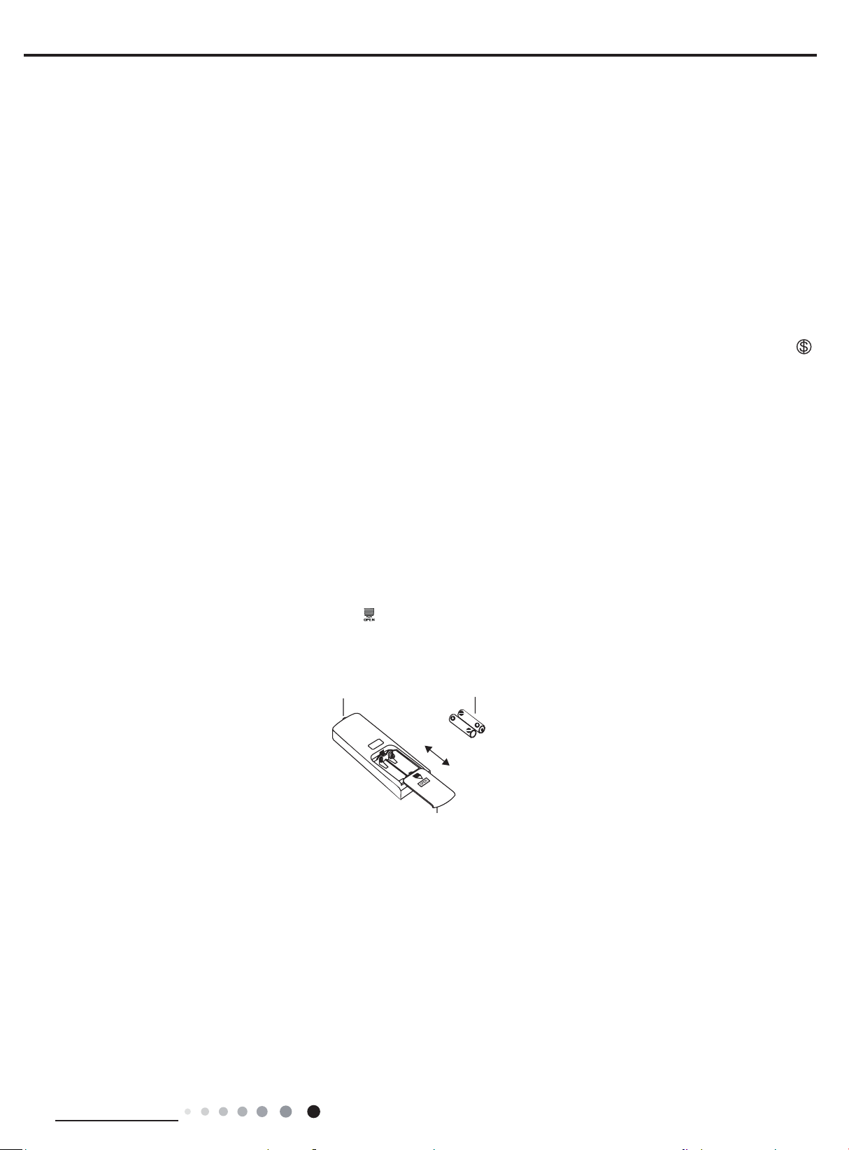
Replacement of batteries in remote controller
1. Press the back side of remote controller marked with " ", as shown in the g, and then push out
arrow direction.
2. Replace two 7# (AAA 1.5V) dry batteries, and make sure the position of "+" polar and "-" polar are correct.
3. Reinstall the cover of battery box.
signal sender battery
reinstall
remove
Cover of battery box
the cover of battery box along the
Technical Information
13
Service Manual
Heating
indicato
Temp.
Coolin
indicato
Power
indicato
r
indicator
6.2 Brief Description of Modes and Functions
1. Summary
(1) Buzzer
When the controller is energized or receives signal from button (emergency operation switch on air conditioner) or remote controller, the
buzzer will give out a beep.
(2) Display
After energization, all icons will be displayed once. Operation icon is in red under standby status. After turning on the unit by remote
◆
controller, operation icon is bright and corresponding set operation mode icon will be displayed (Mode icon include: cooling, heating,
drying).
r
g
r
r
(3) Temperature parameter
Indoor set temperature (Tpreset)
◆
Indoor ambient temperature (Tamb.)
◆
Inner tube temperature of indoor evaporator (Ttube)
◆
2. Introduction of Basic Mode Function
Once the compressor is energized, there should be a minimum interval of 3 mins between two start-ups.
◆
If the unit is with memory function and is off before power failure, the compressor can be restarted without an interval of 3 mins; if the
◆
unit is on before power failure, the compressor will be restarted with an interval of 3 mins.
◆
Once compressor is started, it won’t stop within 6 mins according to the change of room temp.
(1) Auto mode
Operation condition and process for auto mode
①
Under auto mode, the system will automatically select operation mode (cooling, heating, and fan) according to indoor ambient
temperature. There swill be 30s delayed for protection between mode switchover.
When Tamb≥26 , unit will be in cooling mode℃ Ex-factory set temperature is 20
◆
Cooling and heating unit: When Tamb≤(19℃+Tcompensation), unit will be in heating mode Tpreset=20℃.
◆
Cooling only unit: When Tamb≤22℃(or 72℉), unit will be in fan mode Tpreset=25℃.
◆
For cooling and heating unit under condition that (19℃+Tcompensation)<Tamb<26℃ (For cooling only unit under condition that
◆
22℃<Tamb<26℃), when unit is initially turned on in auto mode, it will operate according to auto fan mode. When unit is changed to
auto mode from other modes, it will maintain its previous working status (If auto mode is turned on from
drying mode, unit will operate according to auto fan mode).
② Display: Operation icon, actual operation mode icon, set temperature (that’s the display content of dual-8 nixie tube)
③ Protection function is same as that under each mode.
indicator
drying
Receive
window
℃
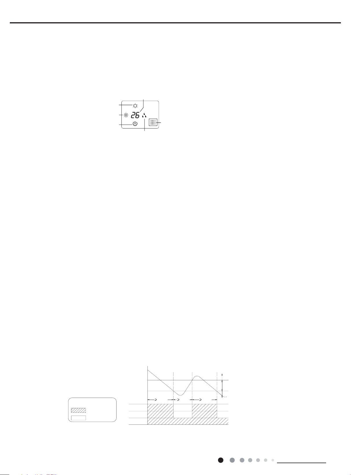
(2) Cooling mode
Operation condition and process for cooling mode
①
When Tamb. ≥Tset+1℃, the system operates under cooling mode. In this case, the compressor, the ODU fan motor and the IDU fan
◆
motor operates at set speed.
When Tamb. ≤Tset-1℃, the compressor and the ODU fan motor stop, while the IDU fan motor operates at set speed.
◆
When Tset-1℃<Tamb. <Tset+1℃, the system will maintain its previous operation status.
◆
In cooling mode, the 4-way valve is de-energized (4-way valve is not available for cooling only unit). Temperature setting range is
16~30℃.
Start cooling
Original operating status
Stop cooling
Technical Information
14
Tpreset +1 ˚C
Tpreset –1 ˚C
Graphic instruction:
(Same as below)
Indicates operation
Indicates stop
Display: Operation icon, cooling icon, set temperature.
②
Outdoor fan motor
Indoor fan motor
Tamb.
6 min. 3 min. 6 min.
Compressor
Set fan speed
Service Manual
T
amb.
Outdoor fan motor
Outdoor fan moto
Protection function
③
Freeze protection
◆
During operation, when controller detected that Ttube≤0℃ for a consecutive period of time, the system enters into freeze protection. In
that case, the compressor and the ODU fan stop operation, while the IDU operates at set fan speed. If freeze protection is released and
the compressor has been out of operation for 3 mins, the unit will resume its previous operation status.
Freeze protection period
Compressor
3 min
r
Indoor fan motor
Overcurrent protection ( this protection function is not available for those models whose cooling capacity ≤12000Btu/h)
◆
Set fan speed
During operation process, if controller detected that system current exceeds the limit value for 3s consecutively (overcurrent), only the
fan operates. About 3 mins later, if overcurrent is released, the system will resume original operation.
If overcurrent protection occurs for 6 times consecutively, and resume operation time won’t exceed 6min every time, overcurrent protection information will be displayed. After turning off the unit, display won’t be displayed.
If turn on the unit again, the system will be restated up again. Overcurrent protection information will be eliminated.
Please refer to maintenance part for display information and disposal method for details.
Locked protection to IDU fan motor
◆
During operation of IDU fan motor, if controller detected that the rotation speed of IDU fan motor less than 300/min or stop rotation, the
motor operates abnormally. In order to prevent damage to motor, controller will protect automatically, the system stops operation and
blocked information of IDU fan motor will be displayed. After turning off the unit, display won’t be displayed.
If turn on the unit again, the system will be restated up again. Blocked information of IDU fan motor will be eliminated. (For some models,
they can only be restated up after re-energized)
Please refer to maintenance part for display information and disposal method for details.
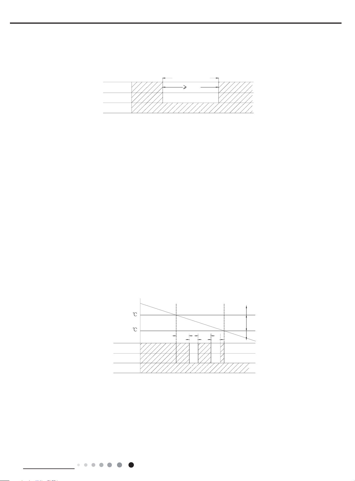
(3) Drying mode
Operation condition and process for drying mode
①
When Tamb. >Tset+2℃, the system starts drying and cooling. In this case, the compressor and the ODU fan motor operate, and the
◆
IDU fan motor operates at low speed.
When Tset-2℃≤Tamb. ≤Tset+2℃, the system will start drying. In this case, the IDU fan motor operates at low speed; the compressor
◆
and the ODU fan motor operate for 6 minutes and stop for 4 minutes in cycle.
When Tamb.<Tset-2℃, the compressor and the ODU fan motor stop, while the IDU fan motor runs at low speed.
◆
In drying mode, the 4-way valve is de-energized (4-way valve is not available for cooling only unit); Temperature setting range is
16~30℃. Fan speed can’t be adjusted.
Display: Operation icon, drying icon, set temperature.
②
Protection function
③
Freeze protection
◆
During dying and cooling operation, when the controller detected that Ttube≤0℃ for a period of time consecutively, the system will enter
into freeze protection. In that case, the compressor and the ODU fan motor stops operation, while the IDU fan motor operates at low
speed. When freeze protection is release and the compressor has stopped for 3min, the system will resume original operation.
During drying operation, when the controller detected that Ttube≤0℃ for a period of time consecutively, the system enters into freeze
protection. In that case, the compressor, the ODU fan motor stops operation, while the IDU fan motor operates at low speed. When
freeze protection is release and the compressor has stopped for 4min, the system will resume original operation.
Other protection is same as that under cooling mode.
◆
(4) Fan mode
Technical Information
T
preset
+2
T
preset-
2
Compressor
Indoor fan motor
6 min
6min.
4min.
Low speed
4min.
Cooling
Drying
Stop
15
Service Manual
Reversing
Operation condition and process for fan mode
①
In fan mode, the IDU fan motor operates at set speed, while the compressor and the ODU fan motor stop. 4-way valve is de-energized
(4-way valve is not available for cooling only unit). Temperature setting range is 16~30℃.
Display: Operation icon, set temperature.
②
Protection function
③
In fan mode, there are overcurrent protection and blocked protection of IDU fan motor. Please refer to corresponding protection function
under cooling mode for details.
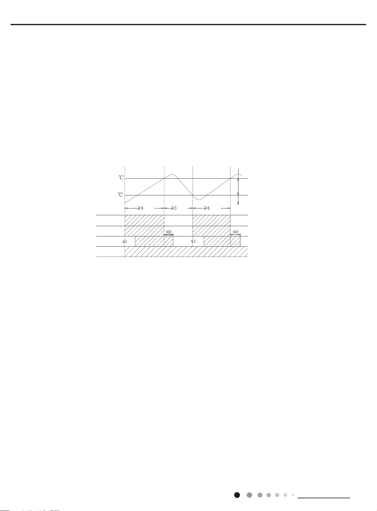
(5) Heating mode(no heating mode is not available for cooling only unit)
Operation conditioner and process for heating mode
①
When Tamb-Tcompensation≤Tpreset-1℃, unit will operate in heating mode. 4-way valve will be energized while compressor and
◆
outdoor fan starts operation at the same time. Indoor fan will start some time later so that air condition won’t blow out cold air.
When Tamb-Tcompensation≥Tpreset+1℃, compressor and outdoor fan will stop operation while 4-way valve is still power on. Indoor
◆
fan will continue operation for a while at set fan speed to blow out the residual heat so that temperature within the air conditioner won’t
be too high.
When Tpreset-1
◆
Tamb-Tcompensation<Tpreset+1℃, system will maintain its previous working status.
℃<
In heating mode, 4-way valve is energized. Temperature setting range is 16~30℃.
T
preset
+4
T
preset
+2
amb
.
T
Compressor
Outdoor unit
Intdoor unit
Display: Operation icon, heating icon, set temperature.
②
Defrosting condition and process
③
min.
valve
min.
min.
.nim.nim
Set fan speedSet fan speed
Stop heating
Original operating status
Start heating
For ensusing heating effect, air conditioner will defrost automatically according to defrosting status on outdoor unit. During defrosting,
heating icon will be on and off.
Protection function
④
Overheating prevention protection
◆
During operation, when controller detects that Ttube≥55℃,the ODU fan motor stops operation; When Ttube is resumed normally, the
ODU fan motor resumes operation.
Noise silencing protection
◆
When turning off the unit or during mode switchover, the 4-way valve is closed. In order to decrease noise, the 4-way valve will delay
2mins to be closed.
Overcurrent protection ( this protection function is not available for those models whose cooling capacity ≤12000Btu/h)
◆
During operation process, if controller detected that system current exceeds the limit value for 3s consecutively(overcurrent), the
system stops operation. About 3mins later, if overcurrent is released, the system will resume original operation. If overcurrent protection
occurs for 6 times consecutively, and resume operation time won’t exceed 6min every time, overcurrent protection information will be
displayed. After turning off the unit, display won’t be displayed.
If turn on the unit again, the system will be restated up again. Overcurrent protection information will be eliminated.
Please refer to maintenance part for display information and disposal method for details.
Locked protection to IDU fan motor
◆
During operation of IDU fan motor, if controller detected that the rotation speed of IDU fan motor less than 300/min or stop rotation, the
motor operates abnormally. In order to prevent damage to motor, controller will protect automatically, the system stops operation and
blocked information of IDU fan motor will be displayed. After turning off the unit, display won’t be displayed.
If turn on the unit again, the system will be restated up again. Blocked information of IDU fan motor will be eliminated. (For some models, they can only be restated up after re-energized)
Please refer to maintenance part for display information and disposal method for details.
16
3. Other Control Function Introduction
(1)Timer function
Technical Information
Service Manual
Clock timer: The precision of clock timer is 1minute. 24hours circulated timer can be set.
Timer ON: If timer ON is set during operation of the unit, the unit will continue to operate. If timer ON is set at unit OFF, upon ON
◆
time reaches, the unit will start to run according to previous setting status.
Timer OFF: If timer OFF is set at unit OFF, the system will keep standby status. If timer OFF is set at unit ON, upon OFF time
◆
reaches, the unit will stop operation.
Timer change:
◆
Although timer has been set, the unit still can be turned on/off by pressing ON/OFF button on the remote controller. You can also reset
the timer.
If timer ON and timer OFF are set at the same time during operation of the unit, the unit will keep running at current status till OFF
time reaches. Upon ON time reached, the system will be turned on automatically. The unit will operate circularly like that every
24hours.
If timer ON and timer OFF are set at unit OFF status, the system keep OFF status till ON time reaches. Upon OFF time reaches, the
system will be turned OFF automatically. The unit will operate circularly like that every 24hours.
(2) Emergency operation switch
After pressing this button, the system will operate according under auto mode and the IDU fan motor operates at auto speed. Swing
motor operates when the IDU fan motor operates. Press this button again to turn off the unit.
Emergency
operation switch
OFF status
Press
ON status(Auto mode)
Press
(3) Sleep function
In this mode, the system will select proper sleep curve to operate according to different set temperature.
If start up sleep function under cooling or drying mode, the system will increase set temperature automatically within a certain
①
range to operate.
If start up sleep function under heating mode, the system will decrease set temperature automatically within a certain range to
②
operate.
(4) Turbo function
Turbo function can be set under cooling and heating modes. During operation of turbo function, the system operates at the maximum
fan speed.
(5) Dry function
Dry function can be set under cooling and drying modes. During operation of drying function, the fan will stop operation after operating
for a period of time when turning off the unit.
(6) Auto fan speed control
Auto fan speed control can be set under cooling, heating and fan mode. During operation of auto fan speed control, the IDU fan motor
will adjust the fan speed (high, medium or low speed) according to ambient temperature.
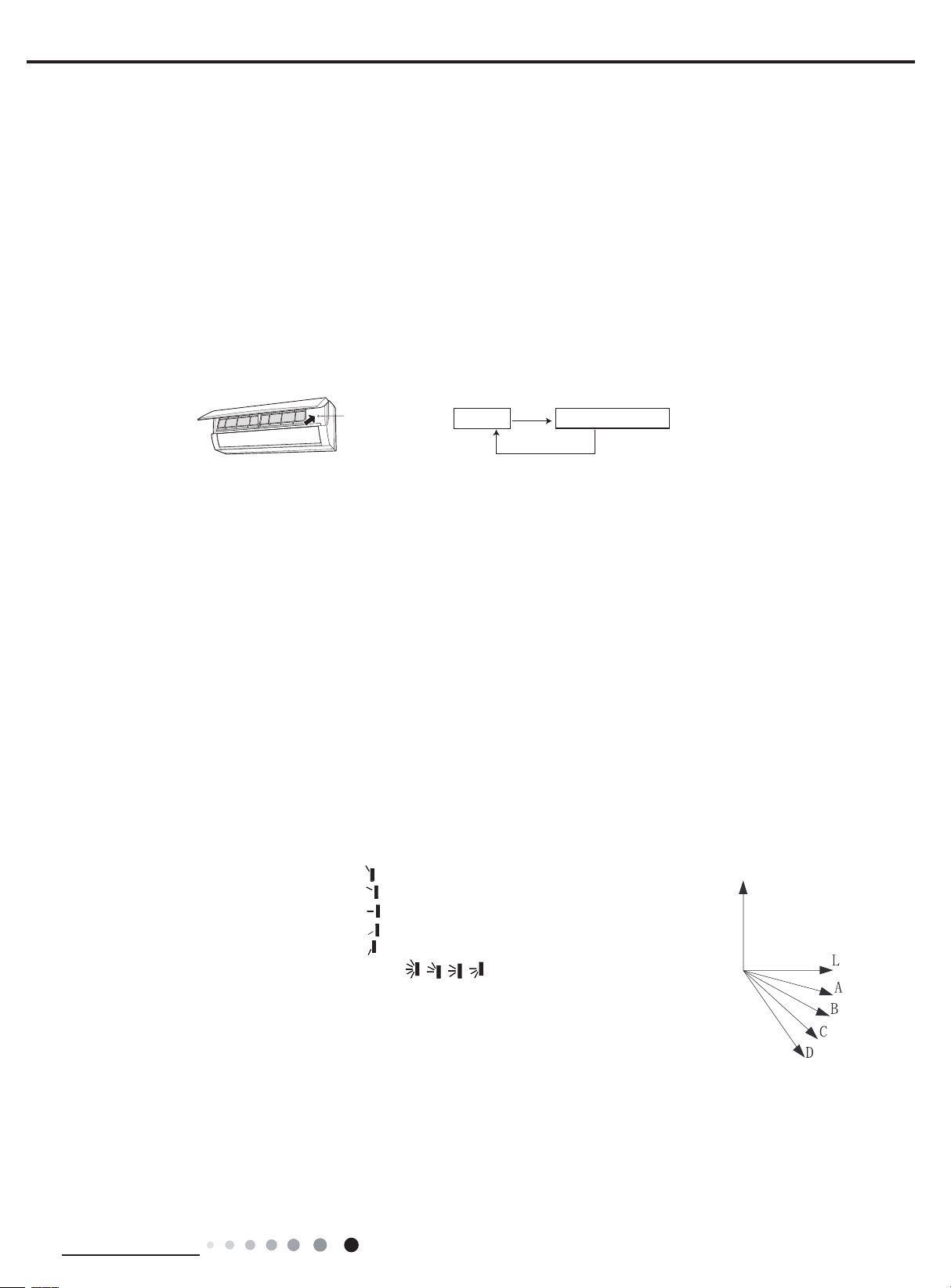
(7) Up&down swing control
After energization, up & down swing motor will rstly have the horizontal louver rotate anticlockwise to position O to close air outlet.
①
If swing function has not been set after start-up of the unit, horizontal louver will turn clockwise to position D in heating mode, or turn
clockwise to level position L in other modes.
If swing function is set when turning on the unit, the horizontal louver will swing between L and D.
②
Horizontal louver has 7 swing statuses:
Stay at position L: control by remote controller:
◆
Stay at position A: control by remote controller:
◆
Stay at position B: control by remote controller:
◆
Stay at position C: control by remote controller:
◆
Stay at position D: control by remote controller:
◆
Swing between L and D: control by remote controller: , , ,
◆
Stop at any postion between L and D (angles between L and D are equiangular) and no display
◆
O(0°)
on remote controller.
When turning off the unit, horizontal louver will close at position O.
③
Swing action is valid only when set swing command and the IDU fan motor is operating.
④
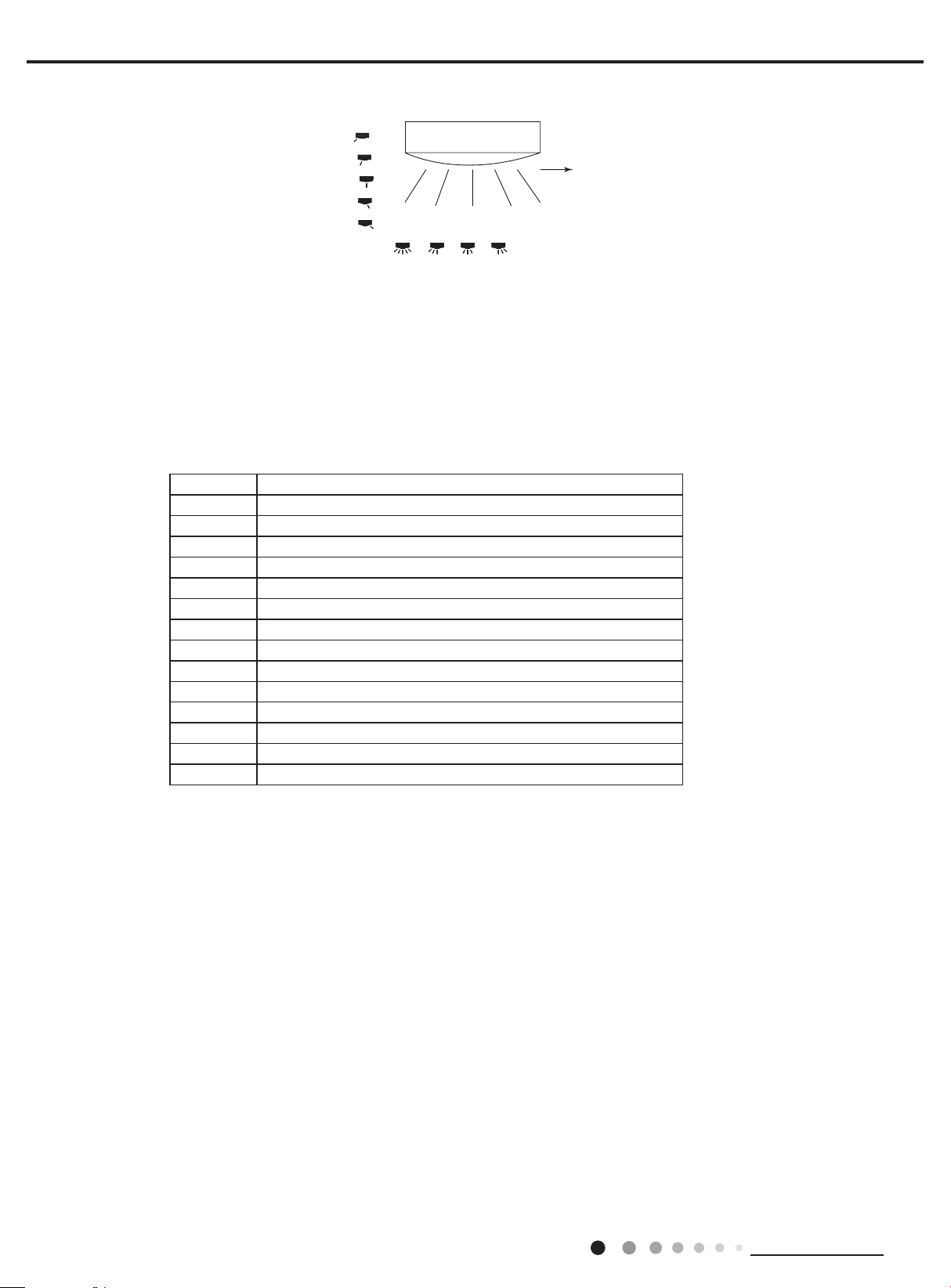
(8) Left&Right swing control(This function is only available for some model)
After energization, swing motor will rstly have the vertical louver rotate anticlockwise to position O to close air outlet. If swing
①
function has not been set after start-up of the unit, vertical louver will turn clockwise to position D in heating mode, or turn clockwise to
position L in other modes.
If swing function is set when turning on the unit, the vertical louver will swing between L and D.
②
Technical Information
17
Service Manual
ǃǃǃǃ
L
A
B
Vertical louver has 7 swing statuses:
Stay at position L: control by remote controller:
◆
Stay at position A: control by remote controller:
◆
Stay at position B: control by remote controller:
◆
Stay at position C: control by remote controller:
◆
Stay at position D: control by remote controller:
◆
Swing between L and D: control by remote controller:
◆
Stop at any position between L and D (angles between L and D are equiangular), control by remote controller: OFF
◆
When turning off the unit, vertical louver will close at position O.
③
Swing action is valid only when swing command has been set and the IDU fan motor is operating.
④
, , ,
C
Set this position as starting point 0(0
D
O
)
(9) Dual-8 nixie tube display
When the air conditioner is turned on for the rst time, dual-8 nixie tube defaulted to display current set temperature.
◆
When controller receives signal of display set temperature, dual-8 nixie tube displays set temperature. When received remote control
◆
signal is switched to indoor ambient temperature display status signal from other display status, dual-8 nixie tube will display indoor
ambient temperature for 3-5s, and then turn back to display set temperature. If remote control to set other status, the display keeps the
same.
When air conditioner has a malfunction,dual-8 nixie tube will show relevant error code.
◆
F1 Indoor ambient temperature sensor is open/short-circuited
F2 Indoor evaporator temperature sensor is open/short-circuited
H6 Blocked protection of IDU fan motor
C5 Malfunction protection of jumper cap
U8 Zero-crossing inspection circuit malfunction of the IDU fan motor
F3 Outdoor ambient temperature sensor is open/short-circuited
F4 Outdoor condenser temperature sensor is open/short-circuited
F5 Outdoor discharge temperature sensor is open/ short-circuited
E1 High pressure protection
E3 Low pressure protection of compressor
E4 High discharge temperature protection of compressor
E5 Overcurrent protection
E6 Communication malfunction
H3 Overload protection compressor
E8 Overload malfunction
When air conditioner is in auto defrosting, heating icon will be on and off.
◆
If turn off light button, all display will be turned off.
◆
(10) Memory function
Power failure when turning on the unit
①
Memory content: ON status, mode, up&down swing, light, set temperature, set fan speed, general timer, Fahrenheit/ Celsius
◆
General timer can be memorized. Time of timer is calculated again from energization.
◆
Clock timer can’t be memorized.
◆
Power failure when turning off the unit
②
Memory content: OFF status, mode, up&down swing, light, set temperature, set fan speed, general timer, Fahrenheit/ Celsius
◆
General timer can be memorized. Time of timer is calculated again from energization.
◆
Clock timer can’t be memorized.
◆
4. Special Function
(1) Health function (for the model with health function)
During operation of the IDU fan motor, press health button on the remote controller to start health function (If there is not health button on
the remote controller, the unit defaults health function ON).
(2) I Feel function (for all models, but it needs the remote controller which can set this function)
When I FEEL command is received, the controller will operate according to the ambient temperature sent by the remote controller (For
defrosting and cold air prevention, the unit operates according to the ambient temperature sensed by the air conditioner). The remote
controller will regularly send ambient temperature data to the controller. When the data has not been received for a long time, the unit
will operate according to the temperature sensed by the air conditioner. If I FEEL function is not set, the ambient temperature will be that
sensed by the air conditioner.
18
Technical Information
 Loading...