

Gree GWH24YE-D3DNA1A, GWH24YE-D3DNA1A/I, GWH18YE-D3DNA1A/I, GWH24YE-D3DNA1A/O, GWH18YE-D3DNA1A/O Service Manual
...
GREE ELECTRIC APPLIANCES,INC.OF ZHUHAI
Change for Life
Service Manual
Models: GWH18YE-D3DNA1A
GWH24YE-D3DNA1A
(Refrigerant R410A)

Table of Contents
Service Manual
Table of Contents
Part
Ⅰ
: Technical Information
.......................................................................1
1. Summary
......................................................................................................................1
2. Specications
..........................................................................................................2
2.1 Specication Sheet ...........................................................................................................2
2.2 Operation Characteristic Curve ........................................................................................4
2.3 Capacity Variation Ratio According to Temperature .........................................................4
2.4 Cooling and Heating Data Sheet in Rated Frequency .....................................................5
2.5 Noise Curve ......................................................................................................................6
3. Outline Dimension Diagram
........................................................................7
3.1 Indoor Unit ........................................................................................................................7
3.2 Outdoor Unit .....................................................................................................................8
4. Refrigerant System Diagram
......................................................................9
5. Electrical Part
.........................................................................................................10
5.1 Wiring Diagram ...............................................................................................................10
5.2 PCB Printed Diagram .....................................................................................................12
6. Function and Control
......................................................................................15
6.1 Remote Controller Introduction .....................................................................................15
6.2 Operation of Smart Control (Smart Phone, Tablet PC) For Gree ...................................20
6.3 Operation of Smart Control (Smart Phone, Tablet PC) .................................................33
6.4 Brief Description of Modes and Functions ......................................................................46
Part
Ⅱ
: Installation and Maintenance
.................................................51
7. Notes for Installation and Maintenance
..........................................51
8. Installation
................................................................................................................53
8.1 Installation Dimension Diagram ......................................................................................53
8.2 Installation Parts-checking ............................................................................................55
8.3 Selection of Installation Location ....................................................................................55
8.4 Electric Connection Requirement ..................................................................................55
8.5 Installation of Indoor Unit ................................................................................................55
8.6 Installation of Outdoor Unit .............................................................................................58
8.7 Vacuum Pumping and Leak Detection ...........................................................................59
8.8 Check after Installation and Test Operation ...................................................................59
8.9 Wired Controller .............................................................................................................60

Table of Contents
Service Manual
9. Maintenance
............................................................................................................70
9.1 Error Code List ...............................................................................................................70
9.2 Procedure of Troubleshooting ........................................................................................77
9.3 Troubleshooting for Normal Malfunction .........................................................................91
10. Exploded View and Parts List
..............................................................93
10.1 Indoor Unit ....................................................................................................................93
10.2 Outdoor Unit .................................................................................................................95
11. Removal Procedure
.......................................................................................97
11.1 Removal Procedure of Indoor Unit ...............................................................................97
11.2 Removal Procedure of Outdoor Unit ..........................................................................102
Appendix:
......................................................................................................................108
Appendix 1: Reference Sheet of Celsius and Fahrenheit ..................................................108
Appendix 2: Conguration of Connection Pipe ...................................................................108
Appendix 3: Pipe Expanding Method .................................................................................109
Appendix 4: List of Resistance for Temperature Sensor ....................................................110
1
Technical Information
Service Manual
1. Summary
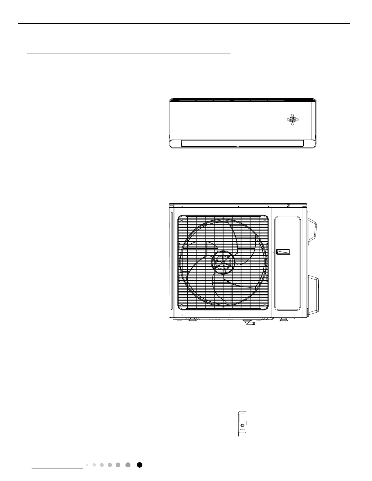
Indoor Unit:
Outdoor Unit:
Remote Controller:
Part
Ⅰ
: Technical Information
GWH18YE-D3DNA1A/O
GWH24YE-D3DNA1A/O
GWH18YE-D3DNA1A/I
GWH24YE-D3DNA1A/I
YAG1FBF
FAN
MODE
ON/OFF
2
Technical Information
Service Manual
2. Specications
2.1 Specication Sheet
Model GWH18YE-D3DNA1A GWH24YE-D3DNA1A
Product Code CB437001500 CB437001700
Power Supply
Rated Voltage V~ 208/230 208/230
Rated Frequency Hz 50/60 50/60
Phases 1 1
Power Supply Mode Outdoor Outdoor
Cooling Capacity(Min~Max) Btu/h 18000(4094~21837) 22000(6800~30700)
Heating Capacity(Min~Max) Btu/h 18000(4094~24566) 24000(6800~32000)
Cooling Power Input(Min~Max) W 1330(350~2500) 1700(450~3700)
Heating Power Input(Min~Max) W 1500(350~2500) 2000(380~3700)
Cooling Power Current A 5.7 7.54
Heating Power Current A 6.2 9.37
Rated Input W 2500 3700
Rated Current A 10.8 16.4
Air Flow Volume(SH/H/MH/M/ML/L/SL) CFM 736/677/618/559/500/457/353 824/765/706/647/589/500/383
Dehumidifying Volume Pint/h 1.8 2.5
EER (Btu/h)/W 13.53 13.00
COP (Btu/h)/W 12.00 12.00
SEER 24.5 21.50
SCOP 12 11.30
Application Area yd
2
27.51-40.7 38.3~59.8
Indoor Unit
Model of indoor unit GWH18YE-D3DNA1A/I GWH24YE-D3DNA1A/I
Indoor Unit Product Code CB437N01500 CB437N01700
Fan Type Cross-ow Cross-ow
Diameter Length(DXL) inch Φ4 1/4X32 11/16 Φ4 3/16X35
Fan Motor Cooling Speed (SH/H/
MH/M/ML/L/SL/Q)
r/min 1400/1300/1200/1100/1000/850/600
1500/1300/1100/1000/900/850/800/6
00
Fan Motor Heating Speed (SH/H/
MH/M/ML/L/SL/Q)
r/min 1400/1250/1100/1000/1050/900/850 1500/1300/1100/1050/1000/900/850
Output of Fan Motor W 60 70
Fan Motor RLA A 0.38 0.24
Fan Motor Capacitor μF / /
Evaporator Form Aluminum Fin-copper Tube Aluminum Fin-copper Tube
Pipe Diameter inch Ф1/4 Ф1/4
Row-n Gap inch 2-1/16 2-1/16
Coil Length (LXDXW) inch 33 1/4X1X13 1/2 33 1/4X1X13 1/2
Swing Motor Model MP35CP/MP24HF MP35CJ
Output of Swing Motor W 2.5/1.5 2.5
Fuse A 3.15 3.15
Sound Pressure Level (SH/H/MH/
M/ML/L/SL)
dB (A) 51/48/45/42/39/36/34 52/48/46/44/42/40/37
Sound Power Level (SH/H/MH/M/
ML/L/SL)
dB (A) 61/58/55/52/49/46/44 62/58/56/54/52/50/47
Dimension (WXHXD) inch 43 11/32X12 56/64X9 51/64 43 11/32X12 56/64X9 51/64
Dimension of Carton Box
(LXWXH)
inch 45 53/64X15 53/64X13 11/32 45 53/64X15 53/64X13 11/32
Dimension of Package (LXWXH) inch 45 15/16X15 15/16X13 15/16 45 15/16X15 15/16X13 15/16
Net Weight Ib 36.4 36.4
Gross Weight Ib 44.1 44.1
3
Technical Information
Service Manual
Outdoor Unit
Model of Outdoor Unit GWH18YE-D3DNA1A/I GWH24YE-D3DNA1A/O
Outdoor Unit Product Code CB437W01500 CB437W01700
Compressor Manufacturer/Trademark
ZHUHAI GREE DAIKIN DEVICE
CO., LTD
ZHUHAI LANDA COMPRESSOR
CO., LTD
Compressor Model QXAT-D20zF030 QXAT-D20zF030
Compressor Oil RB68EP RB68EP
Compressor Type Rotary Rotary
Compressor L.R.A. A 30 30
Compressor RLA 15.5 15.5
Compressor Power Input W 2443 2443
Overload Protector
1NT11L-6233/HPC115/95/
KSD115°C
1NT11L-6233/HPC115/95/
KSD115°C
Throttling Method Electron expansion valve Electron expansion valve
Operation temp ºF 61~86 61~86
Ambient temp (cooling) ºF 0~129 0~129
Ambient temp (heating) ºF -22~75 -22~75
Condenser Form Aluminum Fin-copper Tube Aluminum Fin-copper Tube
Pipe Diameter inch Φ1/4 Φ1/4
Rows-n Gap inch 2-1/16 3-1/16
Coil Length (LXDXW) inch 37 3/16X1 1/2X29 7/16 37 51/64X3 7/16X29 29/64
Fan Motor Speed rpm 820 820
Output of Fan Motor W 90 90
Fan Motor RLA A 0.65 0.65
Fan Motor Capacitor μF / /
Air Flow Volume of Outdoor Unit CFM 2354 4000
Fan Type Axial-ow Axial-ow
Fan Diameter inch Φ17 1/4 Φ21 21/32
Defrosting Method Automatic Defrosting Automatic Defrosting
Climate Type T1 T1
Isolation I I
Moisture Protection IPX4 IPX4
Design Pressure(High) PSIG 550 550
Design Pressure(Low) PSIG 240 240
Sound Pressure Level (H/M/L) dB (A) 59/-/- 59/-/-
Sound Power Level (H/M/L) dB (A) 69/-/- 69/-/-
Dimension (WXHXD) inch 39 3/8X31 7/64X16 13/16 39 3/8X31 7/64X16 13/16
Dimension of Carton Box (LXWXH) inch 42 1/2X19X33 42 1/2X19X33
Dimension of Package (LXWXH) inch 42 41/64X19 7/32X33 21/32 42 41/64X19 7/32X33 21/32
Net Weight Ib 141.1 141.1
Gross Weight Ib 152.1 152.1
Refrigerant R410A R410A
Refrigerant Charge oz 74.1 81.1
Connection
Pipe
Length ft 24.6 24.6
Gas Additional Charge oz/ft 0.5 0.5
Outer Diameter Liquid Pipe inch 1/4 1/4
Outer Diameter Gas Pipe inch 5/8 5/8
Max Distance Height ft 32.8 32.8
Max Distance Length ft 82.0 82.0
Note:The connection pipe applies metric diameter.
The above data is subject to change without notice; please refer to the nameplate of the unit.
4
Technical Information
Service Manual
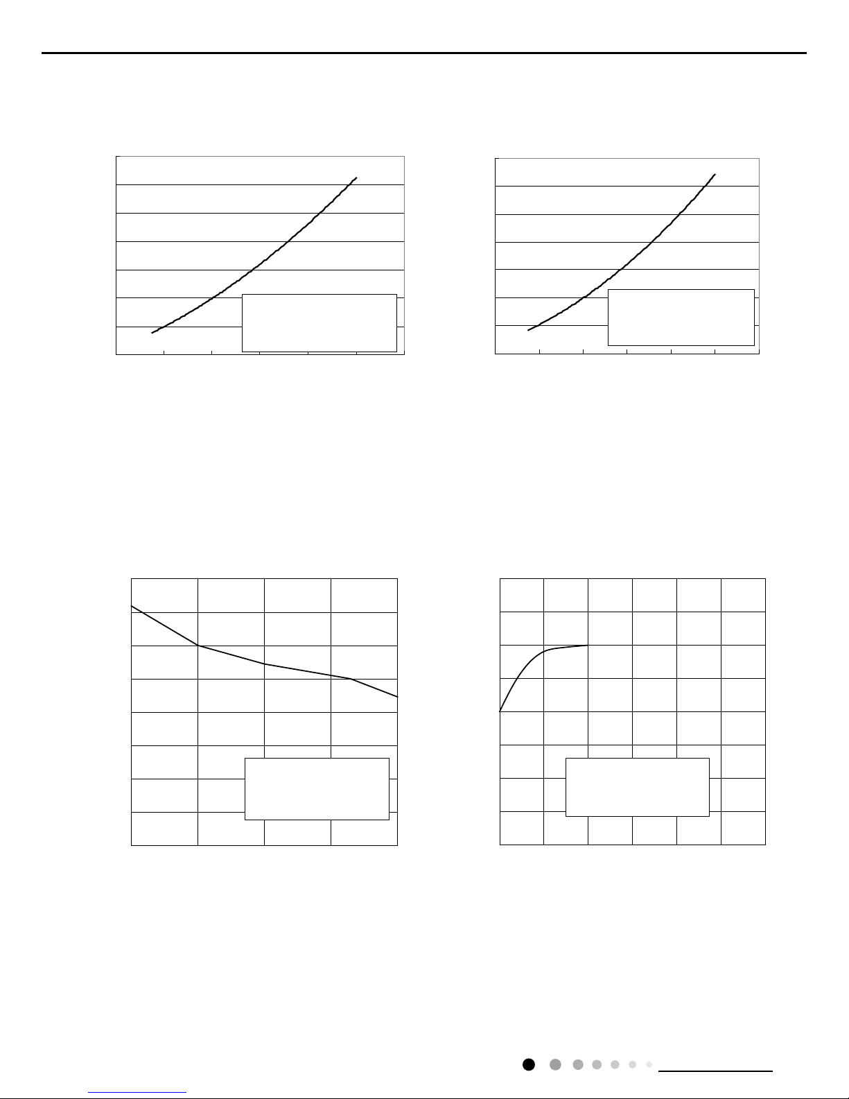
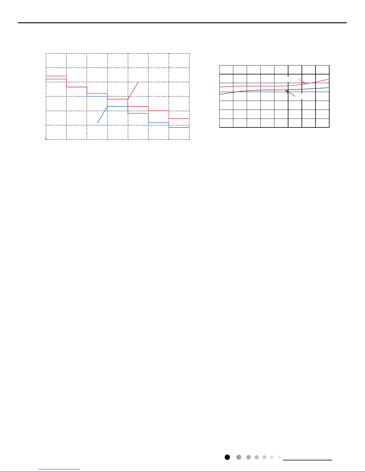
2.2 Operation Characteristic Curve
2.3 Capacity Variation Ratio According to Temperature
Cooling
Cooling
Heating
Heating
Cooling
Heating
24K
0
2
4
6
8
10
12
14
020406080100 120
0
2
4
6
8
10
12
14
020406080 100
120
Conditio
n
Indoor:DB 81°F
WB66
°F
Indoor air flow: Super High
Pipe length:24.6ft
Condition
Indoor:DB 68°F
Indoor air flow: Super High
Pipe length:24.6ft
Compressor Frequency(Hz)
Compressor Frequency(Hz)
Current(A)
Current(A)
Capacity ratio(%)
Capacity ratio(%)
Outdoor temp(°F)
89.695 100.4 107.6 118.4
60
70
80
90
100
110
120
50
40
40
50
120
110
100
90
80
70
60
50
44.63217.6-22-45
Outdoor temp(°F)
Condition
Indoor:DB81°F WB66°F
Indoor air flow: Super High
Pipe length:24.6 ft
Condition
Indoor:DB 68°F
Indoor air flow:Super High
Pipe length:24.6 ft
5
Technical Information
Service Manual
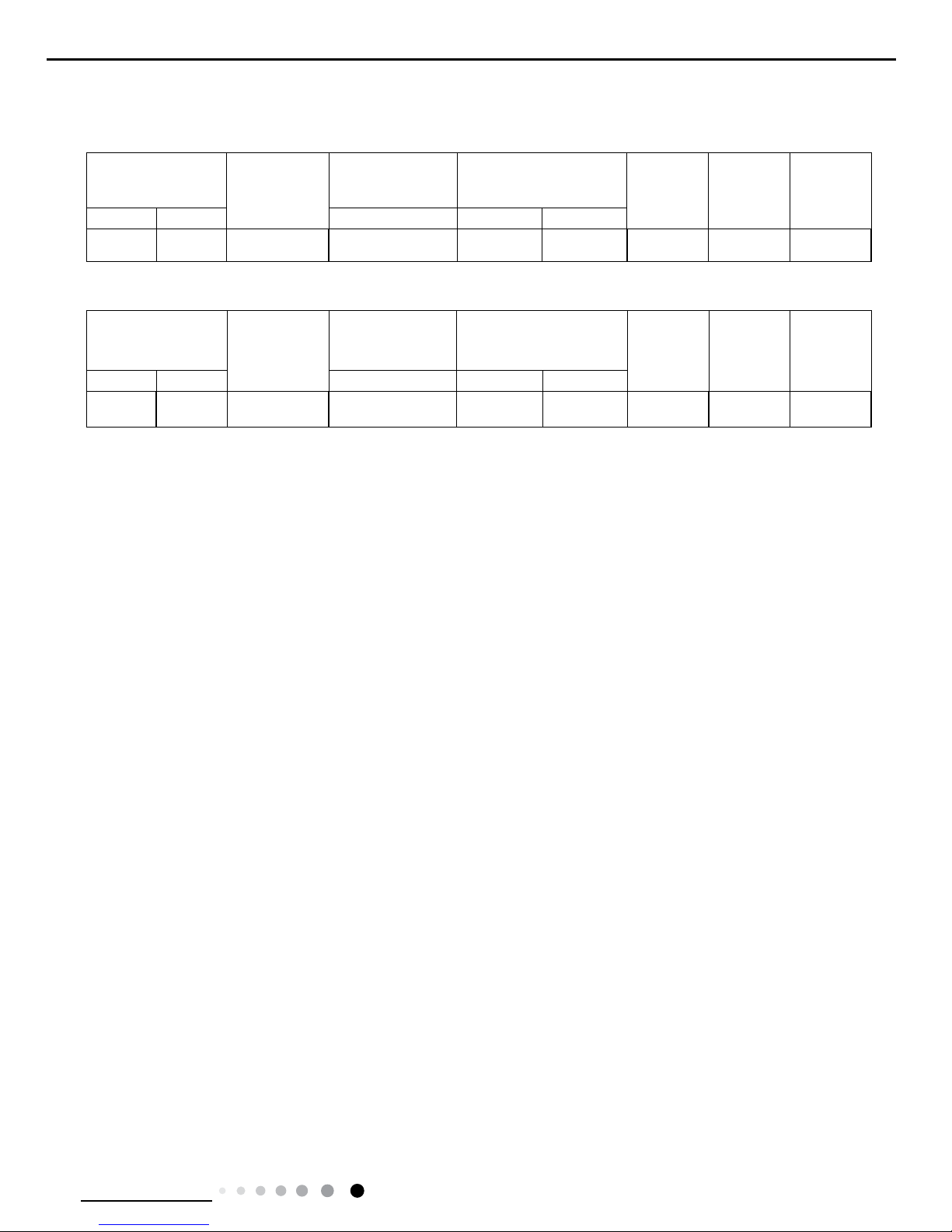
2.4 Cooling and Heating Data Sheet in Rated Frequency
Rated cooling
condition(°F) (DB/WB)
Model
Pressure of gas pipe
connecting indoor
and outdoor unit
Inlet and outlet pipe
temperature of heat
exchanger
Fan speed of
indoor unit
Fan speed of
outdoor unit
Compressor
revolution
(Hz)
Indoor Outdoor PSIG T1 (°F) T2 (°F)
81/66 95/75 18/24K 130.5~159.5 54 to 57 176 to 104 Super High High 75
Rated heating
condition(°F) (DB/WB)
Model
Pressure of gas pipe
connecting indoor
and outdoor unit
Inlet and outlet pipe
temperature of heat
exchanger
Fan speed of
indoor unit
Fan speed of
outdoor unit
Compressor
revolution
(Hz)
Indoor Outdoor P (MPa) T1 (°F) T2 (°F)
68/60 17/16 18/24K 365.3~391.3 158 to 104 34 to 41 Super High High 75
Instruction:
T1: Inlet and outlet pipe temperature of evaporator
T2: Inlet and outlet pipe temperature of condenser
P: Pressure at the side of big valve
Connection pipe length: 24.6ft.
Cooling:
Heating:
6
Technical Information
Service Manual
2.5 Noise Curve
46
48
50
52
54
56
58
60
20 30 40 50 60 70 80 90 100
Compressor frequency(Hz)
Noise dB(A)
Heating
Cooling
55
60
45
50
40
30
35
Indoor fan motor rotating speed
Super
High
Super
Low
Middle
High
Middle
Low
High Middle Low
Noise dB(A)
18K
24K
7
Technical Information
Service Manual
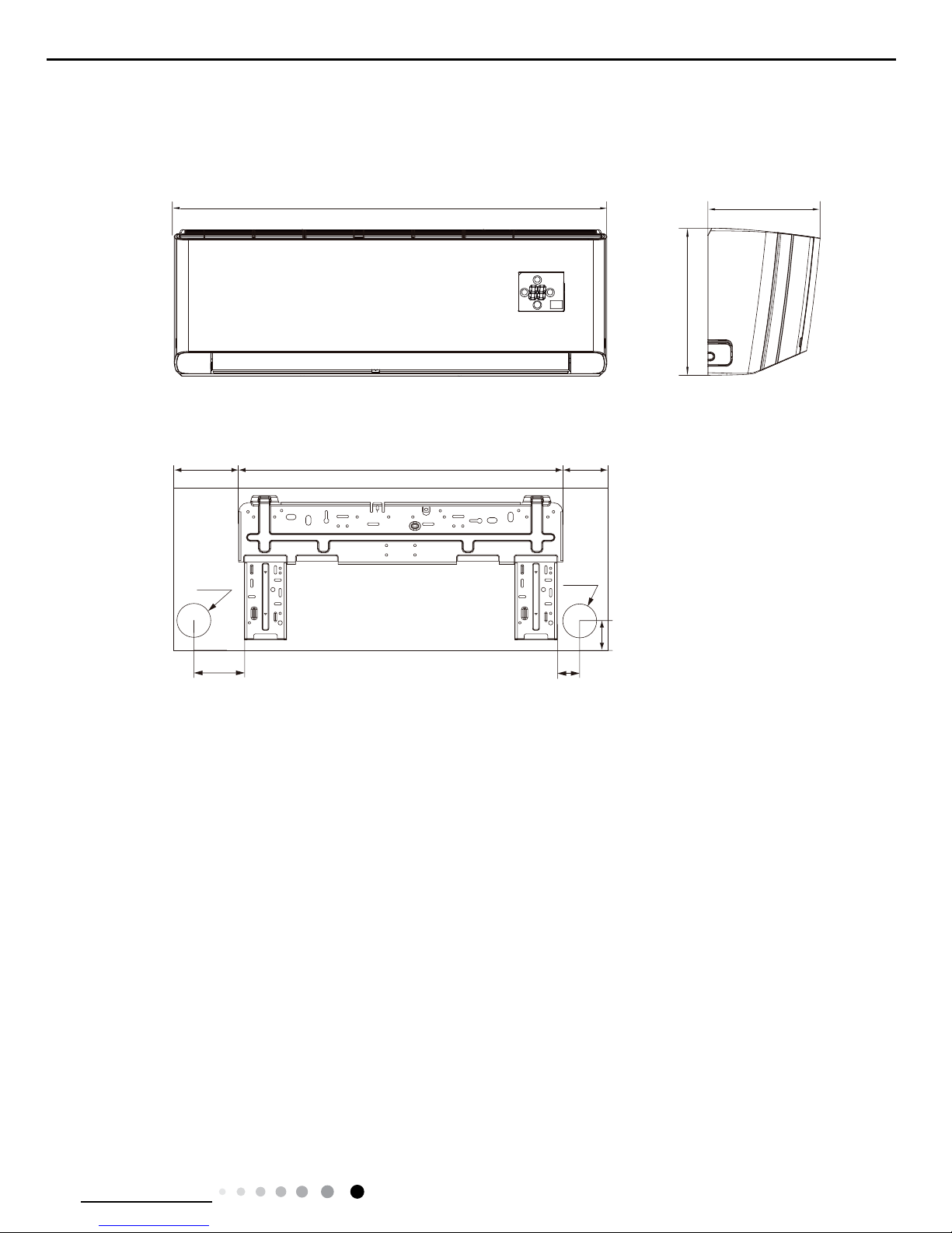
3. Outline Dimension Diagram
3.1 Indoor Unit
Unit:inch
43 11/32
12 56/64
9 51/64
8 9/16
26 15/16
7 27/32
1 11/16
6 1/16
3 1/8
Φ2 3/4Φ2 3/4
8
Technical Information
Service Manual
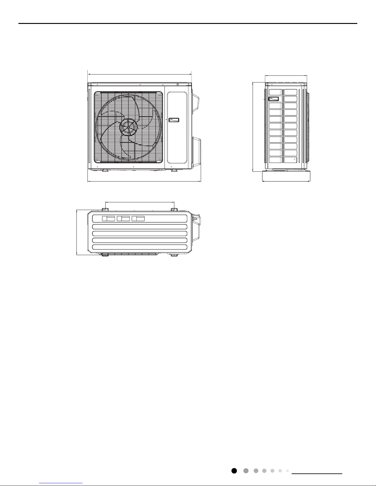
3.2 Outdoor Unit
Unit:inch
14 9/16
31 7
/
64
16 13/16
15 9/16
39 3/8
24
36

9
Technical Information
Service Manual
4. Refrigerant System Diagram
Connection pipe specication:
Liquid : 1/4"
Gas : 5/8"
6HUYLFH0DQXDO
5HIULJHUDQW6\VWHP'LDJUDP
INDOOR UNIT OUTDOOR UNIT
HEAT
EXCHANGE
(EVAPORATOR)
HEAT
EXCHANGE
(CONDENSER)
COMPRESSOR
GAS SIDE
3-WAY VALVE
LIQUID SIDE
2-WAY VALVE
COOLING
HEATING
Accumlator
Discharge
Suction
4-Way valve
Electron
Strainer
Strainer
expansion
valve
Strainer
Capillary
D
Strainer
Intercooler
10
Technical Information
Service Manual
5. Electrical Part
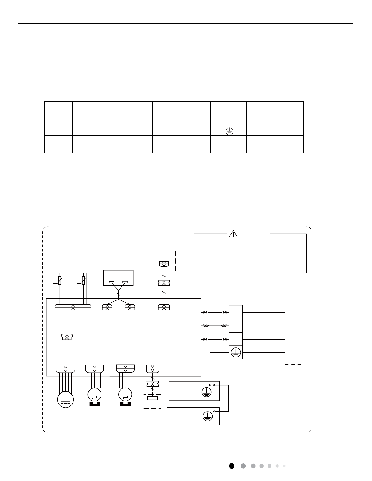
5.1 Wiring Diagram
● Indoor Unit
●Instruction
Symbol Symbol Color Symbol Symbol Color Symbol Name
WH White GN Green CAP Jumper cap
YE Yellow BN Brown COMP Compressor
RD Red BU Blue Grounding wire
YEGN Yellow/Green BK Black / /
VT Violet OG Orange / /
Note: Jumper cap is used to determine fan speed and the swing angle of horizontal lover for this model.
63610000225
67(33,1*
&$3
%/2&.
7(50,1$/
*
(9$325$725
)$1
-803
$30$,1%2$5'
<(*1
%.
%1
<(*1
1
1
;7
%8
$&/
&20287
&200$18$/
&211(&725
$3
:,5('
02725
287'22581,7
76(1625 ',63',63
57
$3
5220
78%(
7(036(1625
7(036(1625
',63/$<%2$5'
5(&(,9(5$1'
57
'&02725
0
6:,1*8'
0
(/(&75,&%2;
*
&21752//(5
:$51,1*
$3
:,),
:,),
02'8/(02725
*1<(*1
%.
5'%1
:+%8
&211(&7,1*
&$%/(
6:,1*/5
0
83'2:1
67(33,1*
02725
/()75,*+7
3OHDVHGRQWWRXFKDQ\HOHFWURQLF
FRPSRQHQWDQGWHUPLQDOZKHQWKH
PDFKLQHLVUXQQLQJVWRSSLQJRUKDV
EHHQSRZHUHGRIIIRUOHVVWKDQ
PLQXWHVWRSUHYHQWHOHFWULFVKRFN
11
Technical Information
Service Manual
3OHDVHGRQWWRXFKDQ\
WHUPLQDOZKHQWKHYROWDJH
RIWHUPLQDO3'&DQG
1'&DW$3LVKLJKHU
WKDQ9WRSUHYHQWWKH
ULVNRIHOHFWULFVKRFN
*
&20B,11(5
<9
:$<9$/9(
/
:
9
8
5($&725
2*:+
9$/9(
(;3$16,21
(/(&7521,&
)$
(.9
35,17('&,5&8,7%2$5'
)$1
*
<(*1
7(036(1625
(;+$867
7(036(1625
2875220
28778%(
7(036(1625
%.:+
%8 <(
&203
;
&203
6$7
:+
29&B&203
2)$1
*
5'
0
575757
*
*
5'%8 <(
8%8 9<( :5'
<(*1
7B6(1625
29(5/2$'3527(&725
:$51,1*
/
0$*1(7,&
5,1*
//
:$<
<9
9
9$/9(
97 97
/
/
,1'&,1'&
$&B/
1
&1
:+
$3
.
.
.
/
*
<(*1
3(
+($7
(+
5'
%27720
+($7(5
%$1'
5'
02725
/
/
32:(5
:+%8
/
/
1
5'%1
%.
:+%8
;7
,1'22581,7
%1
*1<(*1
%/2&.
7(50,1$/
*
0$*1(7,&
%.%1
/
5,1*
%.
%1
%8
%8
/
/
*
<(*1
*1<(*1
0$18$/
7(036(1625
28778%(
57
:+
/
/
/
3OHDVHGRQWWRXFKDQ\
WHUPLQDOZKHQWKHYROWDJH
RIWHUPLQDO3'&DQG
1'&DW$3LVKLJKHU
WKDQ9WRSUHYHQWWKH
ULVNRIHOHFWULFVKRFN
*
&20B,11(5
<9
:$<9$/9(
:
9
8
9$/9($
(;3$16,21
(/(&7521,&
)$5HG
(.9
35,17('&,5&8,7%2$5'
)$1
*
<(*1
7(036(1625
(;+$867
7(036(1625
2875220
28778%(
7(036(1625
%.:+
%8 <(
&203
;
&203
6$7
:+
29&B&203
2)$1
*
5'
0
575757
*
*
8
%'
5<(
8%89<(:5'
<(*1
7B6(1625
29(5/2$'3527(&725
:$51,1*
/
0$*1(7,&
5,1*
//
:$<
<9
:$<
9$/9(
97 97
$&B/
1
&1
:+
$3
.
.
.
*
<(*1
3(
+($7
(+
5'
%27720
+($7(5
%$1'
5'
02725
/
/
32:(5
:+%8
1
5'%1
%.
:+%8
;7
,1'22581,7
%1
*1<(*1
%/2&.
7(50,1$/
*
0$*1(7,&
%.%1
/
5,1*
%.
%1
%8
%8
/
/
*
<(*1
*1<(*1
6(1625
7(036(1625
28778%(
57
:+
/
/
LURQVKHOOPRWRU
RQO\DSSOLHVWRWKH
1RWH0RWRUJURXQG
)$:KLWH
(.9
9$/9(%
(;3$16,21
(/(&7521,&
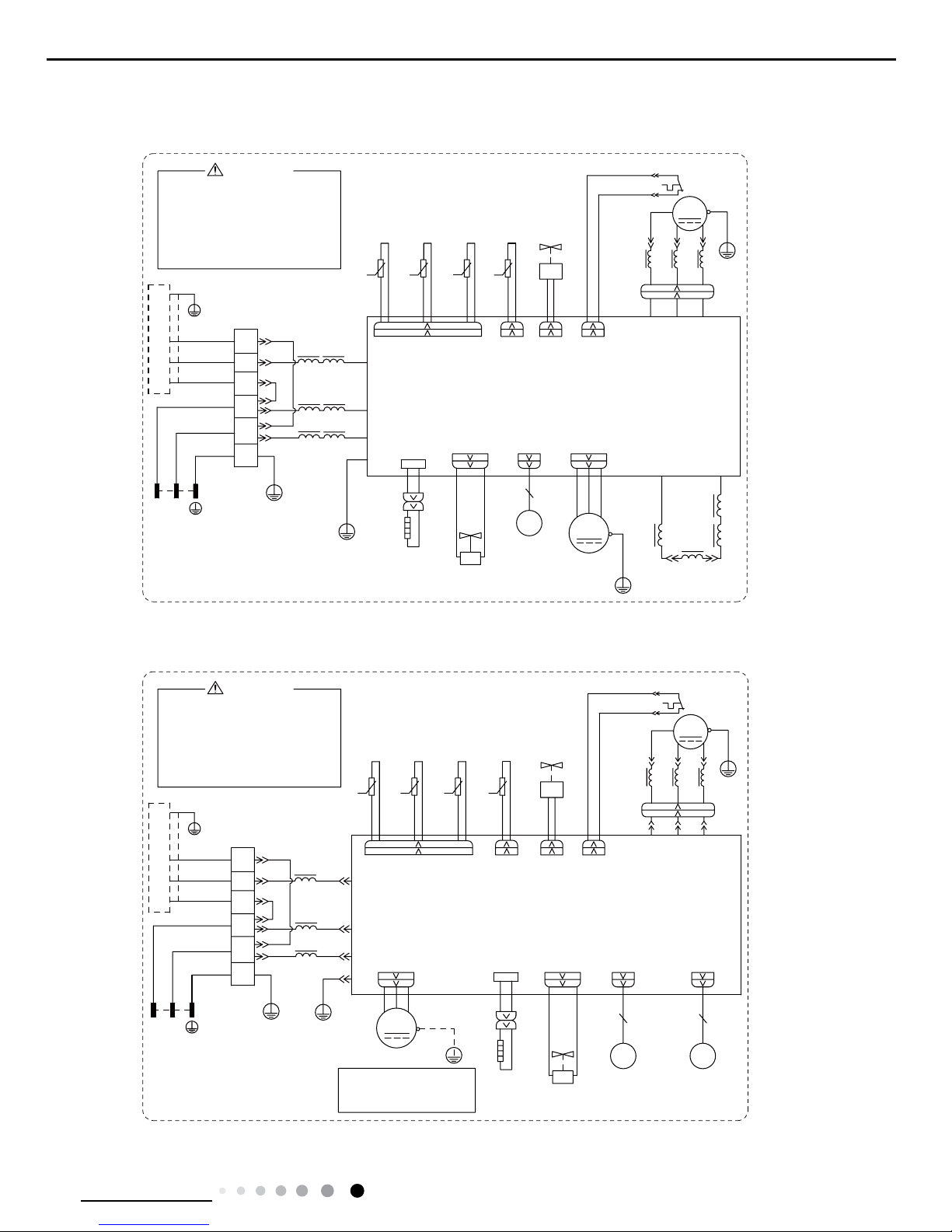
● Outdoor Unit
These wiring diagrams are subject to change without notice; please refer to the one supplied with the unit.
GWH18YE-D3DNA1A/O
GWH24YE-D3DNA1A/O
63610000440
600007000653
12
Technical Information
Service Manual
1216 18
17
34
5
6
7
8
915
11
12
10
13
14
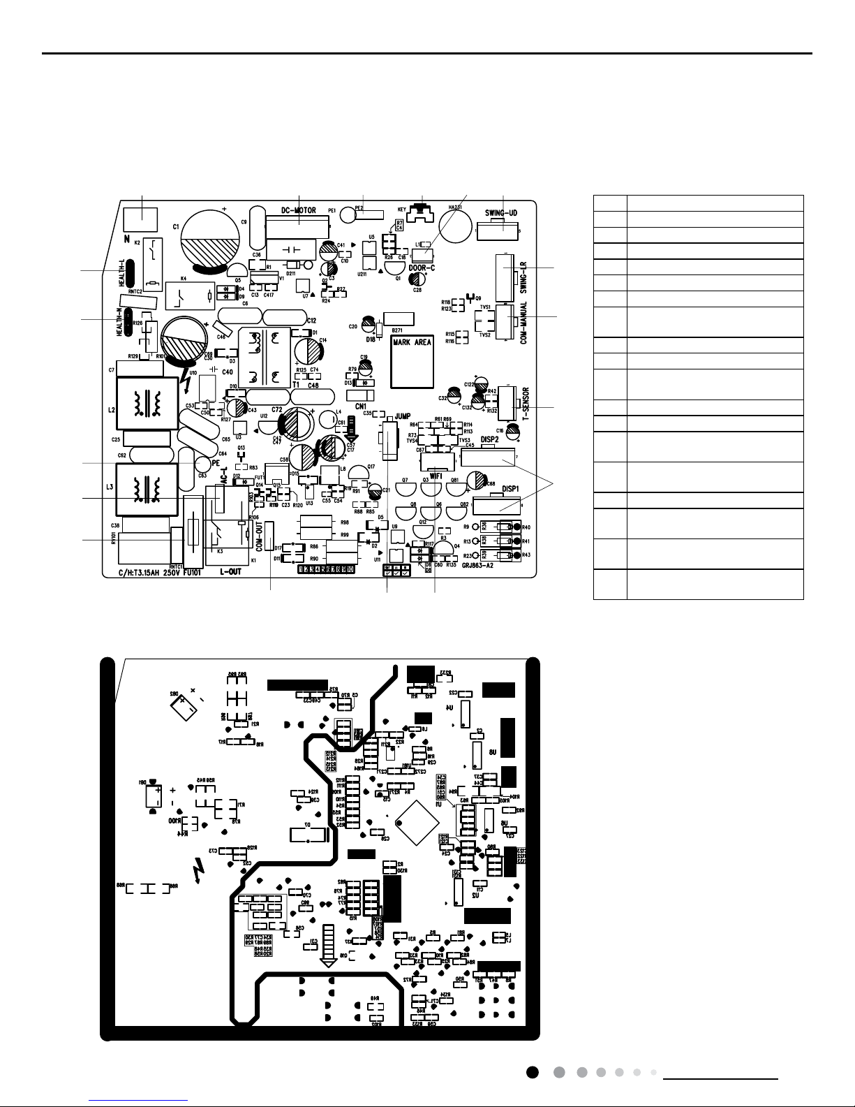
No.Name
1Neutral wire
2Needle stand for indoor fan
3Auto button
4Up&down swing motor
5left&right swing motor
6Interface of temperature sensor
7
Terminal for display board
connection
8Terminal of jumper cap
9Communication wire
10
Connect earthing wire(only fo
r
the mode with this function)
11 Fuse
12 Live wire interface
13
Interface of health function
neutral wire
14
Interface of health function live
wire
15 Detecting plate(WIFI )
16
Connect earthing wire(only fo
r
the mode with this function)
17
Wired controller (only for th
e
mode with this function)
18
Interface of gate control (only
for the mode with this function)
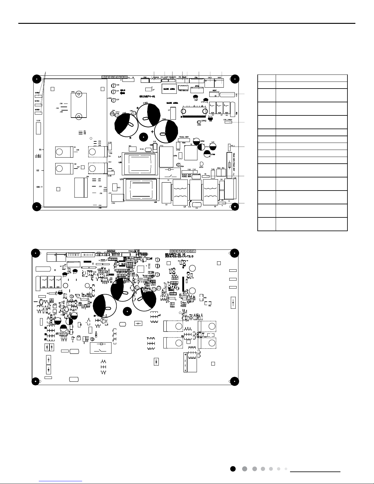
5.2 PCB Printed Diagram
● Top view
Indoor Unit
● Bottom view
13
Technical Information
Service Manual
1234 56
7
8
9
10
11
1
Terminal of compressor
wire
2
Terminal of low pressure
protection
3
Terminal of compressor
overload protection
4
Terminal of outdoor
temperature sensor
5Terminal of outdoor fan
6Terminal of 4-way valve
7
Communication wire
with indoor unit
8Power supply live wire
9Earthing wire
10
Power supply neutral
wire
11 PFC induction wire
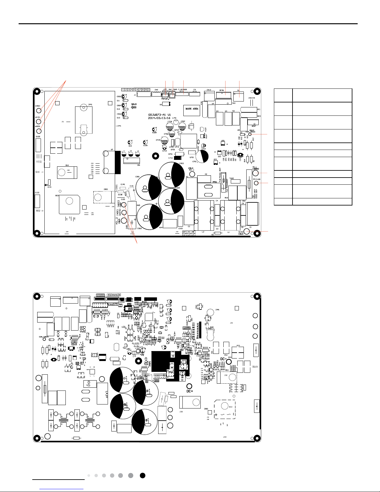
● Top view
● Bottom view
Outdoor Unit
18K
14
Technical Information
Service Manual
● Top view
● Bottom view
1234 56 78 9
10
11
12
13
14
24K
No. Name
1 Interface of compressor
2
Interface of temperature
sensor
3
Terminal of compressor
overload protection
4
Low-temperature cooling
sensor
5 Cooling A valve
6 Cooling B valve
7 Interface of outdoor motor
8 Interface of 2-way valve
9 Interface of 4-way valve
10
Terminal of chassis electric
heating
11
Communication wire with
indoor unit
12
Live wire interface of power
cord
13
Earthing wire interface of cold
plasma
14
Neutral wire interface of
power cord
15
Technical Information
Service Manual
6. Function and Control
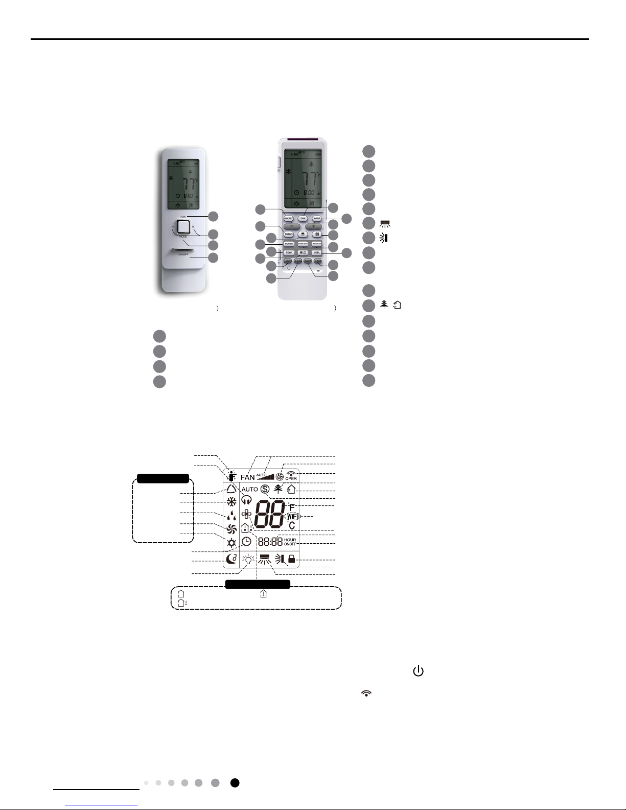
6.1 Remote Controller Introduction
1
2
3
4
5
6
7
8
9
10
11
12
button
button
X-FAN button
QUIET button
SLEEP button
TEMP button
I FEEL button
13
14
15
16
TURBO button
LIGHT button
button
TIMER ON/
TIMER OFF button
CLOCK button
1
2
3
4
ON/OFF button
FAN button
+/- button
MODE button
ON/OFF button
FAN button
+/- button
MODE button
/
1
3
1
13
5
4
3
7
9
6
8
12
14
11
2
4
16
15
10
2
1
(before opening cover (after opening cover
Buttons on Remote Controller
Introduction for Icons on Display Screen
1
2
3
4
5
6
7
8
9
10
11
12
button
button
X-FAN button
QUIET button
SLEEP button
TEMP button
I FEEL button
13
14
15
16
TURBO button
LIGHT button
button
TIMER ON/
TIMER OFF button
CLOCK button
1
2
3
4
ON/OFF button
FAN button
+/- button
MODE button
ON/OFF button
FAN button
+/- button
MODE button
/
1
3
1
13
5
4
3
7
9
6
8
12
14
11
2
4
16
15
10
2
1
(before opening cover (after opening cover
Send signal
Turbo mode
8
ć
(46 ) heating function
Set temperature
Set time
X-FAN function
TIMER ON /TIMER OFF
Child lock
Up & down swing
Left & right swing
Set fan speed
Light
Temp. display type
: Set temp.
: Outdoor ambient temp.
: Indoor ambient temp.
Sleep mode
Clock
Heat mode
Fan mode
Dry mode
Cool mode
Auto mode
Operation mode
I feel
Healthy mode
Scavenging functions
Quiet
Ɖ
This is a general remote controller. Some
models have this function while some do
not. Please refer to the actual models.
Introduction for Buttons on Remote Controller
Note:
● After putting through the power, the air conditioner will give out a sound.Operation indictor " " is ON (red indicator). After that, you can
operate the air conditioner by using remote controller.
● Under on status, pressing the button on the remote controller, the signal icon " " on the display of remote controller will blink once and
the air conditioner will give out a “de” sound, which means the signal has been sent to the air conditioner.
● Under off status, set temperature and clock icon will be displayed on the display of remote controller (If timer on, timer off and light
functions are set, the corresponding icons will be displayed on the display of remote controller at the same time); Under on status, the
display will show the corresponding set function icons.
1. ON/OFF button
Press this button, the unit will be turned on, press it once more, the unit will be turned off. Sleep function will be canceled, while unit off.
16
Technical Information
Service Manual
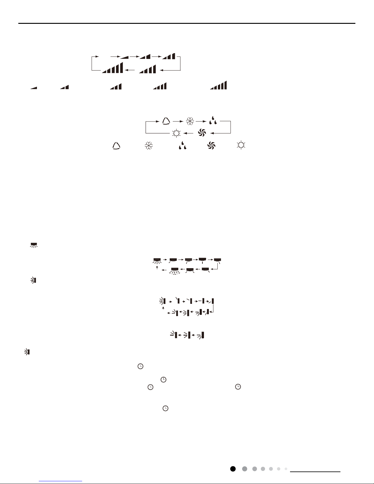
2. FAN button
Press this button, Auto, Low, Medium-low, Medium, Medium-high, High speed can be circularly selected. After powered on, Auto fan speed
is default. Under DRY mode, Low fan speed only can be set up.
3. MODE button
Press this button, Auto, Cool, Dry, Fan, Heat mode can be selected circularly. Auto mode is default while power on. Under Auto mode, the
temperature will not be displayed;Under Heat mode, the initial value is 28°C( 82°F);Under other modes, the initial value is 25°C(77°F).
4. +/- button
● Presetting temperature can be increased.
Press this button,the temperature can be set up, continuously press this button and hold for two seconds, the relative contents can quickly
change,until unhold this button and send the order that the °C(°F) signal will be displayed all the time.The temperature adjustment is
unavilable under the Auto mode, but the order can be sent by if pressing this button.Temperature of Celsius degree setting:16-30;for
Fahrenheit degree setting:61-86.
● Presetting temperature can be decreased.
Press this button, the temperature can be set up, continuously press this button and hold for two seconds, the relative contents can quickly
change,until unhold this button and send the order that the°C(°F) signal will be displayed all the time.The temperature adjustment is
unavailable under the Auto mode,but the order can be sent by if pressing this button.
5. TURBO button
Under Cool or Heat mode,press this button can turn on or turn off the Turbo function.After the Turbo function turned on, the signal of Turbo
will display. The signal will be automatically cancelled if changing the mode or fan speed.
6. button
Press this button to set left & right swing angle cycling as below:
7. button
Press this button to set swing angle,which circularly changes as below:
This remote controller is universal. If it receives threes kinds of following status,the swing angle will remain origial.
If guide louver is stopped when it is swinging up and down,it will remain its present position.
indicates guide louver swings back and forth in the ve places,as shown in the gure.
8. CLOCK button
Press this button, the clock can be set up,signal blink and display.Within 5 seconds, the value can be adjusted by pressing + or - button,
if continuously press this button for 2 seconds above,in every 0.5 seconds, the value on ten place of Minute will be increased 1.During
blinking,repress the Clock button or Conrm button,signal will be constantly displayed and it denotes the setting succeeded. After
powered on, 12:00 is defaulted to display and signal will be displayed. If there is signal be displayed that denotes the current time
value is Clock value, otherwise is Timer value.
9. TIMER ON/TIMER OFF button
● Timer On setting: Signal “ON”will blink and display,signal will conceal,the numerical section will become the timer on setting status.
During 5 seconds blink,by pressing + or - button to adjust the time value of numerical section,every press of that button,the value will be
increased or decreased 1 minute.Hold pressing + or - button,2 seconds later,it quickly change,the way of change is: During the initial 2.5
seconds,ten numbers change in the one place of minute,then the one place is constant,ten numbers change in the ten splace of minute at
2.5 seconds speed and carry. During 5s blink,press the Timer button,the timer setting succeeds.The Timer On has been set up,repress the
timer button,theTimer On will be canceled. Before setting theTimer,please adjust the Clock to the current actual time.
● One press this key to enter into TIMER OFF setup, in which case the TIMER OFF icon will blink. The method of setting is the sameas for
TIMER ON.
Note: It’s Low fan speed
under Dry mode.
(only for cooling and heating unit.
As for cooling only unit, it won’t
have any action when it receives
the signal of heating operation.)
Medium fanLow fan High fa
n
Medium-low fan Medium-high fan
ATUO
Medium fanLow fan High fan
Medium-low fan Medium-high fan
ATUO
AUTO COOL DRY FAN HEAT
OFF
OFF
OFF
OFF
OF
F
OFF
OFF
OFF
OFF
OFF
OFF
OFF
OFF
OFF
17
Technical Information
Service Manual
10. TEMP button
Press this button, you can see indoor set temperature, indoor ambient temperature or outdoor ambient temperature on indoor unit’s
display. The setting on remote controller is selected circularly as below:
no display
When selecting "
" with remote controller or no display, temperature indicator on indoor unit displays set temperature; When selecting
"
" with remote controller,temperature indicator on indoor unit displays indoor ambient temperature; When selecting " " with remote
controller, temperature indicator on indoor unit displays outdoor ambient temperature. 3s later it will return to the setting temprature or it
depends on the other received signal within 3s.
Attention: When displaying the outdoor ambient, the displaying range is 32-99°F and 0-60°C.When it goes beyond the range, it keeps the
threshold data (the smallest—0°C or 32°F and the largest 99°F or 60°C).
Warm tips: When operating buttons on the cover please make sure the cover is closed completely.
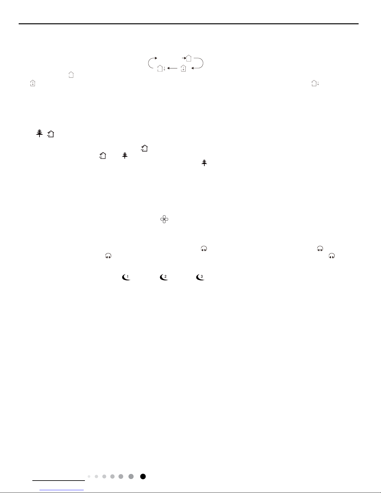
11.
/
button(This function is only available for some models)
Press this button to achieve the on and off of healthy and scavenging functions in operation status.Press this button for the rst
time to start scavenging function;LCD displays“
”.Press the button for the second time to start healthy and scavenging functions
simultaneously;LCD displays“
”and “
” .Press this button for the third time to quit healthy and scavenging functions simultaneously.
Press the button for the fourth time to start healthy function; LCD display“
” .Press this button again to repeat the operation above.
12. I FEEL button
Press this button once, to turn on the I FEEL function, then the gure of "I FEEL" will be displayed, after every press of other function
button, every 200ms to send I FEEL once, after this function started,the remote control will send temperature to the main un it in every 10
minutes.When repress this button, this function will be turned off.
13. LIGHT button
Press this button at unit On or Off status,Light On and Light Off can be set up.After powered on, Light On is defaulted.
14. X-FAN button
Pressing X-FAN button in COOL or DRY mode,the icon
is displayed and the indoor fan will continue operation for 2 minutes in order
to dry the indoor unit even though you have turned off the unit.After energization, X-FAN OFF is defaulted.X-FAN is not available in
AUTO,FAN or HEAT mode.
15. QUIET button
Press this button,the Quiet status is under the Auto Quiet mode (display"
" and “Auto”signal ) and Quiet mode(display "
" singal) and
Quiet OFF(there is no signal of "
" displayed),after powered on,the Quiet OFF is defaulted. Under the Quiet mode (Display "
"signal),
the fan speed is not available.
16. SLEEP button
●Press this button, can select Sleep 1 (
), Sleep 2 ( ),Sleep 3 (
) and cancel the Sleep, circulate between these, after
electried, Sleep Cancel is defaulted.
●Sleep 1 is Sleep mode 1, in Cool, Dehumidify modes: sleep status after run for one hour, the main unit setting temperature will increase
1°C(1ºF~2ºF), 2 hours,setting temperature increased 2°C(3ºF~4ºF), the unit will run at this setting temperature; In Heat mode: sleep status
after run for one hour, the setting temperature will decrease 1°C(1ºF~2ºF), 2 hours, setting temperature will decrease 2°C(3ºF~4ºF), then
the unit will run at this setting temperature.
●Sleep 2 is sleep mode 2, that is air conditioner will run according to the presetting a group of sleep temperature curve.
In Cool mode:
(1) When setting the initial temperature 16~23°C(61ºF~74ºF), after turned on Sleep function, the temperature will be increased 1°C(1ºF~2ºF)
in every hour,after 3°C(5ºF~6ºF) the temperature will be maintained, after 7hours,the temperature will be decreased 1°C(1ºF~2ºF), after
that the unit will keep on running under this temperature;
(2) When setting the initial temperature 24~27°C(75ºF~81ºF), after turned on Sleep function, the temperature will be increased 1°C(1ºF~2ºF)
in every hour,after 2°C(3ºF~4ºF) the temperature will be maintained, after 7hours,the temperature will be decreased 1°C(1ºF~2ºF) , after
that the unit will keep on running under this temperature;
(3) When setting the initial temperature 28~29°C(82ºF~85ºF), after turned on Sleep function, the temperature will be increased 1°C(1ºF~2ºF)
in every hour, after 1°C(1ºF~2ºF) the temperature will be maintained, after 7hours,the temperature will be decreased 1°C(1ºF~2ºF) , after
that the unit will keep on running under this temperature;
(4) When setting the initial temperature 30°C(86ºF), under this temperature setting, after 7hours, the temperature will be decreased
1°C(1ºF~2ºF), after that the unit will keep on running under this temperature;
In Heat mode:
(1) Under the initial presetting temperature 16°C(61ºF), it will run under this setting temperature all along.
(2) Under the initial presetting temperature17~20°C(62ºF~68ºF), after Sleep function started up, the temperature will decrease 1°C(1ºF~2ºF)
in every hour, after 1°C(1ºF~2ºF) decreased, this temperature will be maintained.
(3) Under the initial presetting temperature 21~27°C(69ºF~81ºF), after Sleep function started up, the temperature will decrease
1°C(1ºF~2ºF) in every hour,after 2°C(3ºF~4ºF) decreased, this temperature will be maintained.
(4) Under the initial presetting temperature 28~30°C(82ºF~86ºF), after Sleep function started up, the temperature will decrease
1°C(1ºF~2ºF) in every hour, after 3°C(5ºF~6ºF) decreased, this temperature will be maintained.
18
Technical Information
Service Manual
●Sleep 3- the sleep curve setting under Sleep mode by DIY:
(1) Under Sleep 3 mode, press "Turbo" button for a long time, remote control enters into user individuation sleep setting status, at this
time, the time of remote control will display "1hour ", the setting temperature "88" will display the corresponding temperature of last setting
sleep curve and blink (The rst entering will display according to the initial curve setting value of original factory);
(2) Adjust "+" and "-" button, could change the corresponding setting temperature, after adjusted, press "Trubo "button for conrmation;
(3) At this time, 1hour will be automatically increased at the timer postion on the remote control, (that are "2hours" or "3hours" or "8hours "),
the place of setting temperature "88" will display the corresponding temperature of last setting sleep curve and blink;
(4) Repeat the above step (2)~(3) operation, until 8hours temperature setting nished, sleep curve setting nished, at this time, the remote
control will resume the original timer display;temperature display will resume to original setting temperature.
●Sleep3- the sleep curve setting under Sleep mode by DIY could be inquired:
The user could accord to sleep curve setting method to inquire the presetting sleep curve, enter into user individuation sleep setting
status, but do not change the temperature, press "Turbo" button directly for conrmation.
Note: In the above presetting or enquiry procedure, if continuously within10s, there is no button pressed, the sleep curve setting status will
be automatically quit and resume to display the original displaying. In the presetting or enquiry procedure, press "ON/OFF" button, "Mode"
button, "Timer" button or "Sleep" button, the sleep curve setting or enquiry status will quit similarly.
17. About X-FAN function
This function indicates that moisture on evaporator of indoor unit will be blowed after the unit is stopped to avoid mould.
(1)Having set X-FAN function on: After turning off the unit by pressing ON/OFF button indoor fan will continue running for about 2 min. at
low speed. In this period, press X-FAN button to stop indoor fan directly.
(2)Having set X-FAN function off: After turning off the unit by pressing ON/OFF button, the complete unit will be off directly.
18. About AUTO RUN
When AUTO RUN mode is selected, the setting temperature will not be displayed on the LCD, the unit will be in accordance with the room
temp. automatically to select the suitable running method and to make ambient comfortable.
19. About turbo function
If start this function, the unit will run at super-high fan speed to cool or heat quickly so that the ambient temp. approachs the preset temp.
as soon as possible.
20. About lock
Press + and - buttons simultaneously to lock or unlock the keyboard. If the remote controlleris locked, the icon
will be displayed on it, in
which case, press any button, the mark will icker for three times. If the keyboard is unlocked, the mark will disappear.
21. About swing up and down
(1)Press swing up and down button continuously more than 2s,the main unit will swing back and forth from up to down, and then loosen
the button, the unit will stop swinging and present position of guide louver will be kept immediately.
(2)Under swing up and down mode, when the status is switched from off to
OFF
, if press this button again 2s later,
OFF
status will switch
to off status directly; if press this button again within 2s,the change of swing status will also depend on the circulation sequence stated
above.
22. About swing left and right
(1)Press swing left and right button continuously more than 2s,the main unit will swing back and forth from left to right, and then loosen the
button, the unit will stop swinging and present position of guide louver will be kept immediately.
(2)Under swing left and right mode, when the status is switched from off to
, if press this button again 2s later,
status will switch
to off status directly; if press this button again within 2s,the change of swing status will also depend on the circulation sequence stated
above.
23. About switch between Fahrenheit and Centigrade
Under status of unit off, press MODE and - buttons simultaneously to switch °C and °F.
24. Combination of " TEMP" and "CLOCK" buttons : About Energy-saving Function
Press “TEMP” and “CLOCK” simultaneously in COOL mode to start energy-saving function.Nixie tube on the remote controller displays “SE”.
Repeat the operation to quit the function.
25. Combination of " TEMP" and "CLOCK" buttons : About 8°C(46ºF) Heating Function
Press “TEMP” and “CLOCK” simultaneously in HEAT mode to start 8°C(46ºF) Heating Function.Nixie tube on the remote controller
displays"
"and a selected temperature of “8°C” (46°F if Fahrenheit is adopted). Repeat the operation to quit the function.
26. About Auto Quiet function
When auto quiet function is selected:
(1)Under cooling mode: indoor fan operates at notch 4 speed. 10 minutes later or when indoor ambient temperature≤28°C(82ºF), indoor
fan will operate at notch 2 speed or quiet mode according to the comparison between indoor ambinet temperature and set temperature.
(2)Under heating mode: indoor fan operates at notch 3 speed or quiet mode according to the comparison between indoor ambient
temperature and set temperature.
(3)Under dry, fan mode: indoor fan operates at quiet mode.
(4)Under auto mode: the indoor fan operates at the auto quiet mode according to actual cooling, heating or fan mode.
27. About Sleep function
Under the Fan and Auto mode, the Sleep function cannot be set up, under Dehumidify mode, only Sleep 1 can be selected.Select and
enter into any kind of Sleep mode, the Quiet function will be attached and stared, different Quiet status could be optional and turned off.
19
Technical Information
Service Manual
1
4
3 1
2
4
2
3
5
battery
Cover of battery box
remove
reinstall
1
4
3 1
2
4
2
3
5
battery
reinstall
1
4
3 1
2
4
2
3
5
Operation Guide
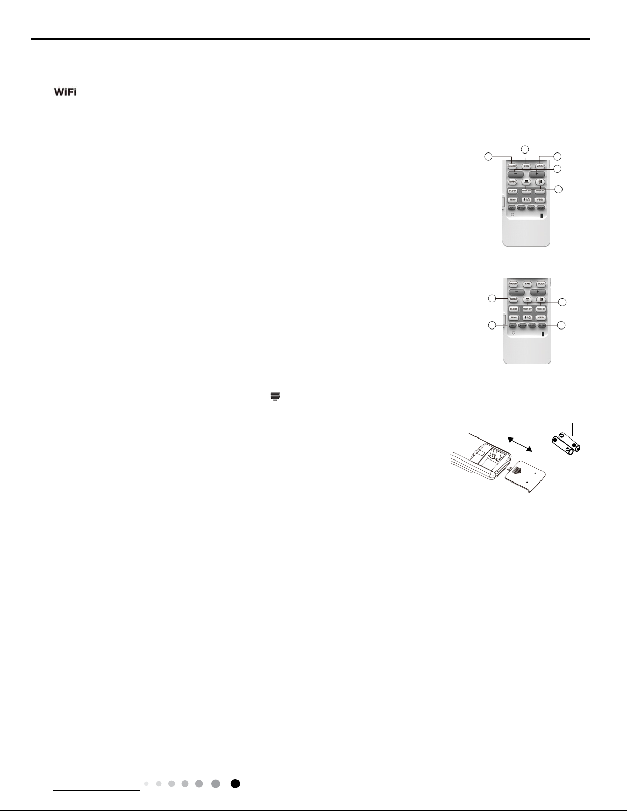
28.WIFI Function
Replacement of Batteries in Remote Controller
1. General operation
(1)After powered on, press ON/OFF button, the unit will start to run. (Note: When it is powered on, the
guide louver of main unit will close automatically.)
(2)Press MODE button, select desired running mode.
(3)Pressing + or - button, to set the desired temperature (It is unnecessary to set the temp. at AUTO
mode.)
(4)Pressing FAN button, set fan speed, can select AUTO FAN,LOW, MEDIUM-LOW, MEDIUM, MEDIUM-
HIGH and HIGH.
(5)Pressing and button, to select the swing.
2. Optional operation
(1)Press SLEEP button, to set sleep.
(2)Press TIMER ON and TIMER OFF button, can set the scheduled timer on or timer off.
(3)Press LIGHT button, to control the on and off of the displaying part of the unit (This function may be not
available for some units).
(4)Press TURBO button, can realize the ON and OFF of TURBO function.
1. Press the back side of remote controller marked with " ",as shown in the g,and then push out the
cover of battery box along the arrow direction.
2. Replace two 7# (AAA 1.5V) dry batteries, and make sure the position of "+" polar and "-" polar are
correct.
3. Reinstall the cover of battery box.
Note:
● During operation, point the remote control signal sender at the receiving window on indoor unit.
● The distance between signal sender and receiving window should be no more than 8m, and there
should be no obstacles between them.
● Signal may be interfered easily in the room where there is uorescent lamp or wireless telephone;
remote controller should be close to indoor unit during operation.
● Replace new batteries of the same model when replacement is required.
● When you don’t use remote controller for a long time, please take out the batteries.
● If the display on remote controller is fuzzy or there’s no display, please replace batteries.
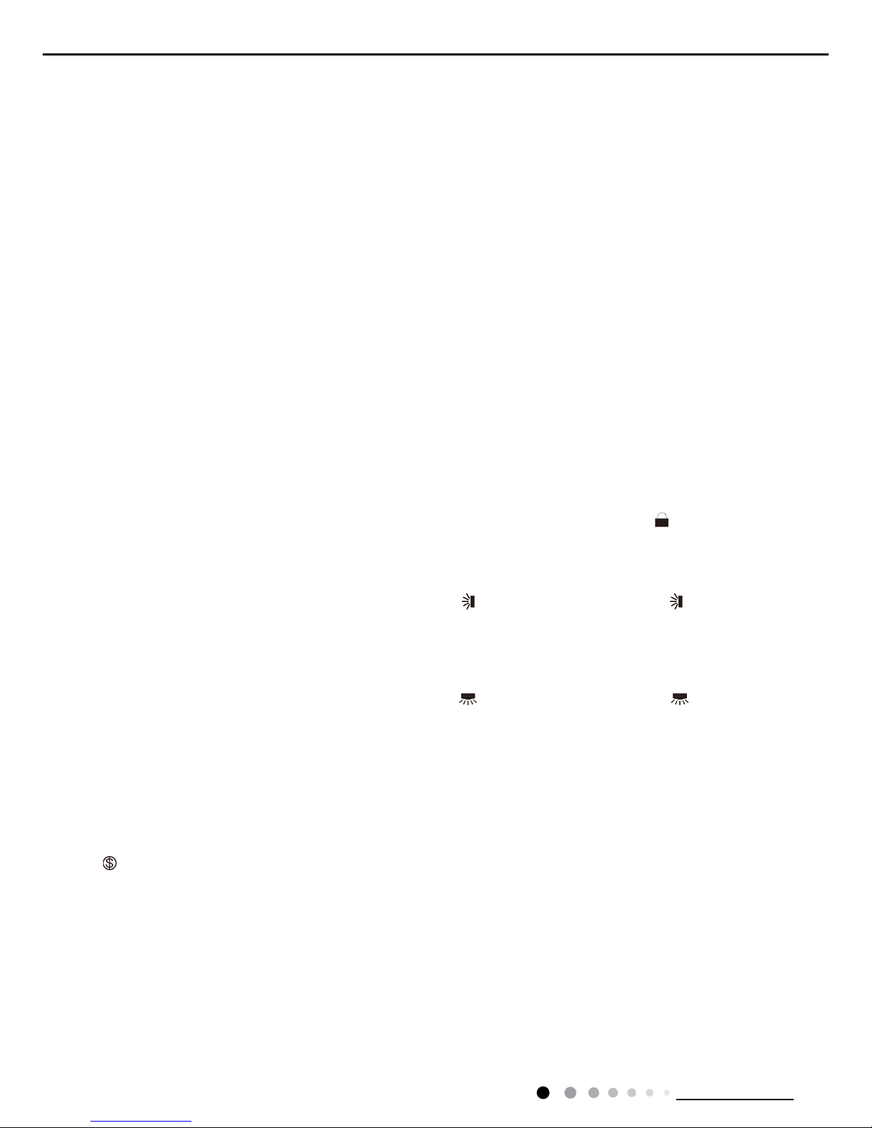
Press "MODE" and "TURBO" button simultaneously to turn on or turn off WIFI function. When WIFI function is turned on, the
" " icon will be displayed on remote controller; Long press "MODE" and "TURBO" buttons simultaneously for 10s, remote
controller will send WIFI reset code and then the WIFI function will be turned on. WIFI function is defaulted ON after energization
of the remote controller.(This function only applicable for some models. )
20
Technical Information
Service Manual
6.2 Operation of Smart Control (Smart Phone, Tablet PC) For Gree
NOTE:One AC can be controlled by 4 smart phones in maximum at the same time.
(2).Short-distance and long-distance control setting for air conditioner connecting with router
Step 1: Under short-distance control, return to the homepage "Home Control". Tap at the top right corner of the homepage "Device".
Operation Instructions
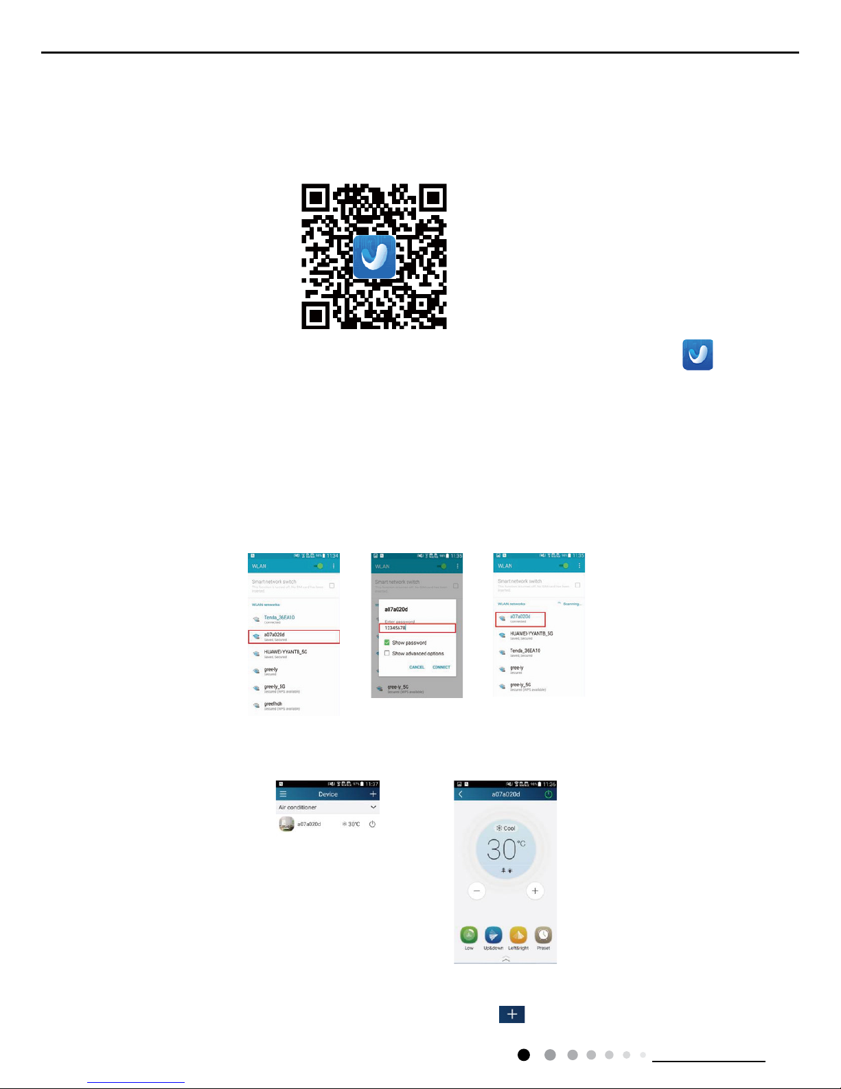
Download and install APP
Scan the following QR code with your smart phone and download Wi Smart.
Conguration
Step 2: Open APP and the screen will show the air conditioner that you just connected. Tap the name of this air conditioner on
your phone to enter and realize short-distance control, as shown below. Please refer to "Functions introduction" for specic control
methods.
Install the APP according to its guidance. When successfully installed, your smart phone homepage will show this icon
User of IOS system can search for the Gree Smart in Apple store to download the Apple version APP.
NOTE: Select either the original conguration or AP conguration according to the APP functions.
1.Original conguration
Before operation, please nish the following conguration in order to realize Wi control and the connection between air conditioner and
intelligent device.
(1).Short-distance control setting for air conditioner using Wi hotspot
Step 1: Air conditioner Wi is set in AP mode in factory. You can search the air conditioner Wi hotspot through your smart phone. The
name of Wi hotspot is the last 8 numbers of the air conditioner mac address. Password is 12345678.
21
Technical Information
Service Manual
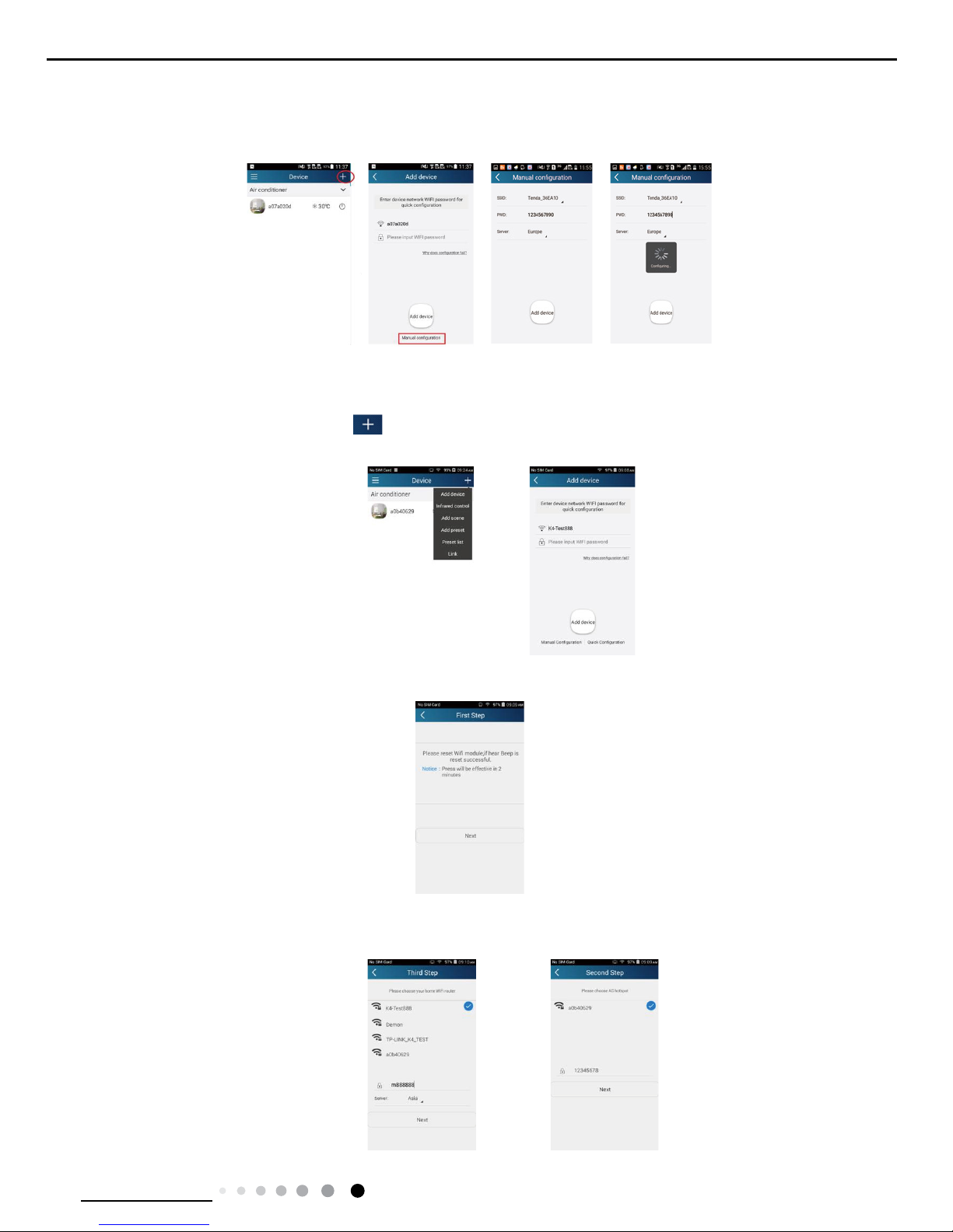
2.AP conguration
4 steps of conguration
Step 1: Enter homepage "Device", and then tap at the top right corner.
Select "Add device" and enter the page "Add device". Tap "Manual Conguration".
Step 2: Tap "Next" in the First Step.
Step 3: Select the wireless network of air conditioner. APP will show the password 12345678 (default password of the network of air
conditioner). Then tap "Next"; select the name of home Wi router, then enter the correct password and select a server.
Select "Add device" and enter the page of "Add device". Tap "Manual conguration" and enter the page "Manual conguration".
Step 2: Select the correct network name and enter the password. Select the server (The server setting here must keep the same as the
server setting in "Settings" mentioned below. Otherwise, remote control will fail.), then tap the button "Add device" for conguration. At
this time, "Conguring" is displayed on the APP. The buzzer in the indoor unit will give out a sound when conguration succeeds.
22
Technical Information
Service Manual
Step 4: If conguration is successful, a window will pop up and read "Conguration succeeded". Then conguration is completed.
NOTE: After conguration is completed, the air conditioner hot spot connected to your phone will disAPPear. You should reconnect your
phone to the home Wi router to realize long-distance control.
The above conguration only needs one phone. Other types of phones shall install this APP, connect with the air conditioner hot spot or
wireless router of Wi air conditioner. When connection is done, open the APP to use short-distance operation to control the air conditioner
and then you can use the long-distance control.
Functions introduction
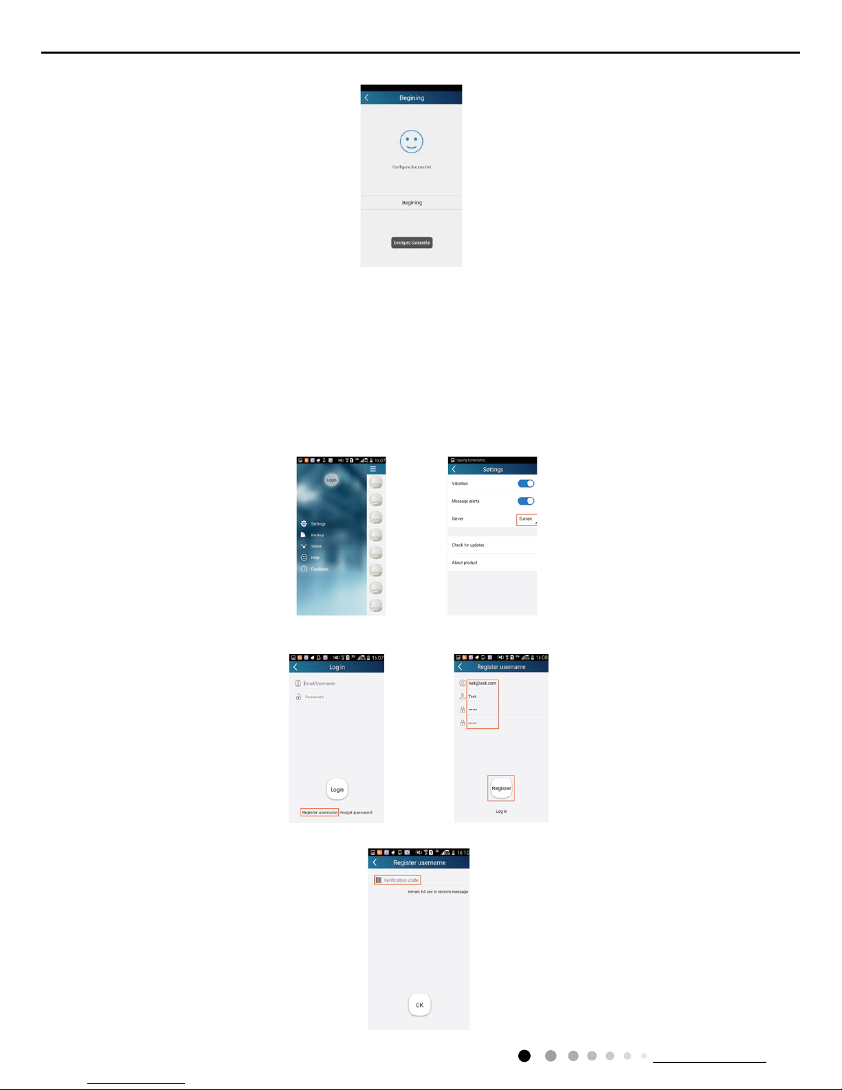
1.User registration
Purpose: To realize long-distance control
Operation instruction: For the rst time login, you have to register a new username. If you already have a username, skip the registration
step and enter email address and password on the "Login Page" to log in. If password is forgotton, you can reset the password.
Operation steps:
(1) Select the sever address
(2) Account login: Slide the page "Device", and enter the page "Menu" on the left. Tap "Login" to enter the page "Register username". New
user must rst register a username. Tap "Register”.
(3) Enter your email address. Wait until you receive the verication code. Enter the code and then tap "OK" to log in.
23
Technical Information
Service Manual
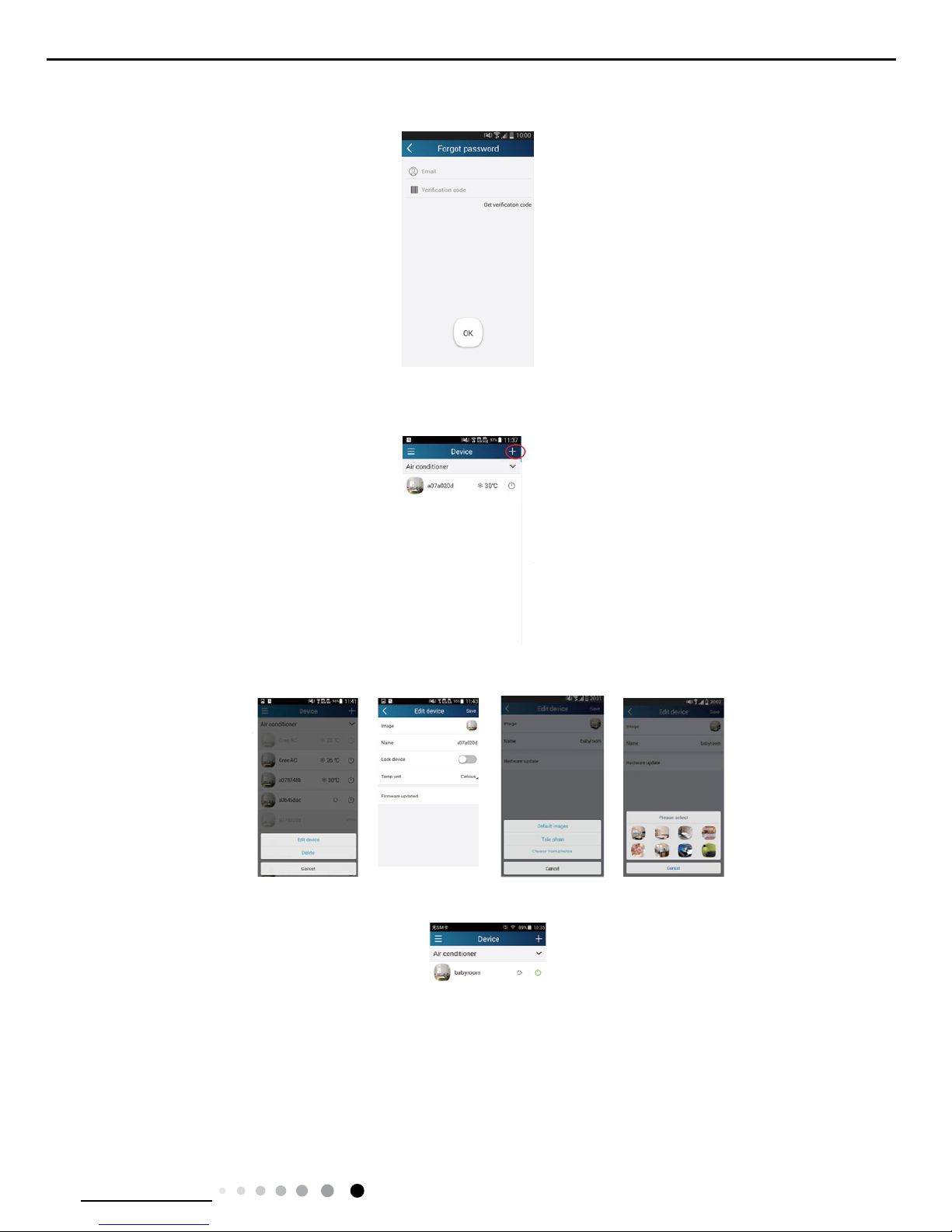
(4) If password is forgotten, you can reset the password with your email address.
Tap "Forgot password" and enter the page "Forgot password". Tap "Get verication code" to get an email verication code. Enter a new
password and tap "OK" to log in.
2.Personal settings
Purpose: Set name (device name, preset name, etc.) and images (device image) in order to identify a user easily.
(1) Set device name
After quick conguration, a list of controllable smart devices will be generated. Default name for air conditioner is the last 8 numbers of the
air condtioner mac address.
Step 1: Tap and hold "a0b417ac" to enter the page "Edit device". Tap "Image" to select the source of image. Select from "Default images"
or "Take photo" or "Choose from photos" and save an image.
Step 2: Tap "Name" to change device name. Save it and the new device name will be shown. Enable button ''Lock device'' to lock the
device so that other smart phones can’t search the device. Tap "Temp unit" to change the temperature unit.
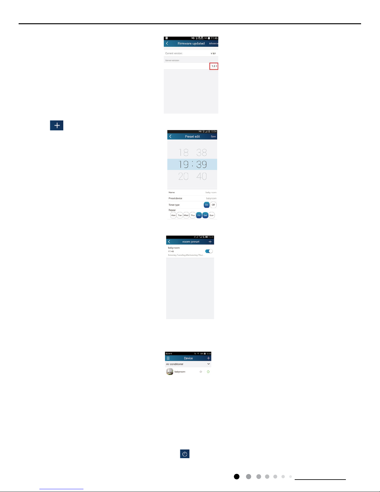
Step 3: Tap "Firmware update" to upgrade the rmware of the device. Tap"1.8" and then the device will be updated automatically.
24
Technical Information
Service Manual
(2) Set preset name
Step 1: Tap at the top right corner of the homepage "Device". Select "Add preset" and enter the page "Preset edit".
Step 2: Choose the time. Tap "Name". As shown in the picture, its name is "baby room". For timer type, select "On". Then select the
repeating days. Save the setting of preset name.
(3) Set device image
Please refer to step 1 in 2(1)
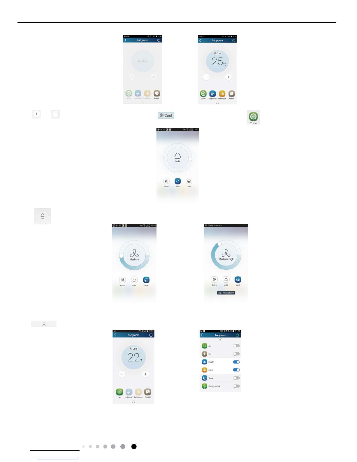
3.Control functions
(1) Common control functions: General control on the operation of smart devices (On/Off, temperature, fan speed, mode, etc.) and the
setting of advanced functions (air exchange, dry, health, light, sleep, energy saving upper limit).
Step 1: General control
Enter the homepage "Home control" rst. Take "babyroom"as an example.
Tap "babyroom" and enter the page of air conditioner control. Tap to turn on the control switch.
25
Technical Information
Service Manual
Tap or to increase or decrease temperature. Tap to change working mode. Tap to enter the page of fan speed
adjustment.
Tap and go around the circle to adjust fan speed.
Step 2: Advanced settings
Tap to enter advanced settings. You may select "Air", "Dry", "Health", "Light", "Sleep" or "Energy saving".
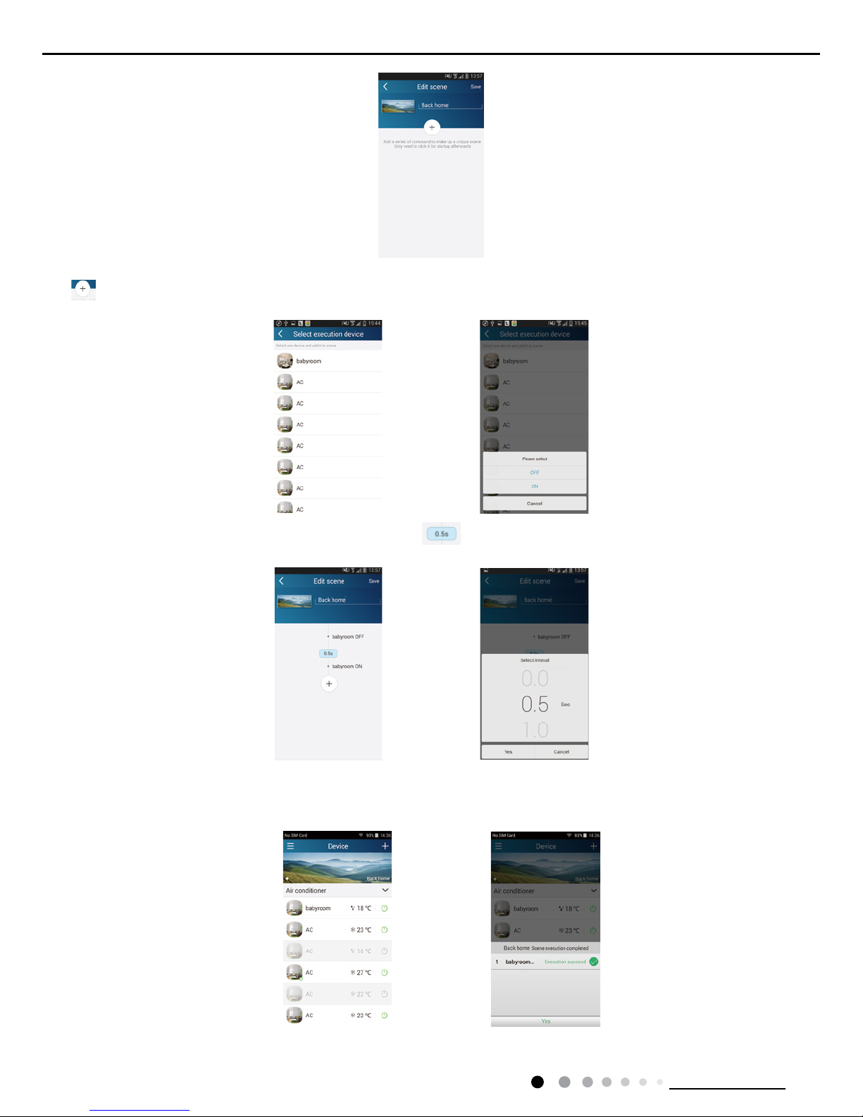
(2) Advanced control functions: Set scene; Preset; Link; Infrared control (only APPlicable to smart phones with infrared emitter)
Set scene: Preset the operation of several smart devices by one tap.
On the page "Home control", tap the image of "Home control" to enter the page "Edit scene".
26
Technical Information
Service Manual
Tap "Add scene" and edit the scene name, for example, "Back home". Add execution devices.
Tap to add commands. On the page "Select execution device", select the air conditioner named "babyroom". Then select "ON" or
"OFF".
Continue to select the next execution device as instructed above. Tap to set the interval.
Tap "Save". Tap the scene picture displayed on homepage "Device" to send the command. Then the scene "Back home" will be in execution.
You may view the execution condition of the scene.

27
Technical Information
Service Manual
(3) Preset includes single-device preset and multi-device preset
Single-device preset: This can preset a certain device to be On/Off at a specic time.
On the homepage "Device", take air conditioner "babyroom" as an example. Tap at the bottom of the page "babyroom". Then you will
enter the page "Preset edit".
Slide up and down to set the time. If you need to synchronize the time, tap " synchronize". If such "Hint" interface doesn't show up, please
skip this operation step.
Tap "Name" to customize the preset name.
Preset device can’t be selected and it will default to "babyroom". Select "On" for the timer type. Select repeating days to complete the
preset.
Multi-device preset: This can preset multiple devices to execute a command at a specic time.
Please refer to the instructions as how to set preset time, name, timer type and repeating days for a single device.
Tap "Preset device" to select one or more devices. Then return to the page "Device".
 Loading...