

Gree GWH18TC-S3DNA1D, GWH18TC-S3DNA2D, GWH24TD-S3DNA1D Service Manual

GREE ELECTRIC APPLIANCES,INC.OF ZHUHAI
Change for Life
Service Manual
Models: GWH18TC-S3DNA1D
GWH18TC-S3DNA2D
GWH24TD-S3DNA1D
(Refrigerant R410A)

Service Manual
Table of Contents
Table of Contents
Part
Ⅰ
: Technical Information
.......................................................................1
1. Summary
......................................................................................................................1
2. Specications
..........................................................................................................2
2.1 Specication Sheet ...........................................................................................................2
2.2 Operation Characteristic Curve ........................................................................................6
2.3 Capacity Variation Ratio According to Temperature .........................................................6
2.4 Noise Curve ......................................................................................................................7
2.5 Cooling and Heating Data Sheet in Rated Frequency .....................................................7
3. Outline Dimension Diagram
........................................................................8
3.1 Indoor Unit ........................................................................................................................8
3.2 Outdoor Unit .....................................................................................................................9
4. Refrigerant System Diagram
....................................................................10
5. Electrical Part
.........................................................................................................11
5.1 Wiring Diagram ...............................................................................................................11
5.2 PCB Printed Diagram .....................................................................................................14
6. Function and Control
......................................................................................17
6.1 Remote Controller Introduction .....................................................................................17
6.2 Operation of Smart Control (Smart Phone, Tablet PC) ..................................................23
6.3 Operation of Smart Control (Smart Phone, Tablet PC) For Gree ...................................34
6.4 Brief Description of Modes and Functions ......................................................................45
Part
Ⅱ
: Installation and Maintenance
.................................................53
7. Notes for Installation and Maintenance
..........................................53
8. Installation
................................................................................................................55
8.1 Installation Dimension Diagram ......................................................................................55
8.2 Installation Parts-checking ............................................................................................57
8.3 Selection of Installation Location ....................................................................................57
8.4 Electric Connection Requirement ...................................................................................57
8.5 Installation of Indoor Unit ................................................................................................57
8.6 Installation of Outdoor Unit .............................................................................................60
8.7 Vacuum Pumping and Leak Detection ...........................................................................61
8.8 Check after Installation and Test Operation ...................................................................61

Service Manual
Table of Contents
9. Maintenance
............................................................................................................62
9.1 Flashing LED of Indoor/Outdoor Unit and Primary Judgement ......................................62
9.2 Procedure of Troubleshooting ........................................................................................65
9.3 Troubleshooting for Normal Malfunction .........................................................................82
10. Exploded View and Parts List
..............................................................84
10.1 Indoor Unit ....................................................................................................................84
10.2 Outdoor Unit .................................................................................................................89
11. Removal Procedure
.......................................................................................93
11.1 Removal Procedure of Indoor Unit ...............................................................................93
11.2 Removal Procedure of Outdoor Unit ..........................................................................107
Appendix:
......................................................................................................................118
Appendix 1: Reference Sheet of Celsius and Fahrenheit ..................................................118
Appendix 2: Conguration of Connection Pipe ...................................................................118
Appendix 3: Pipe Expanding Method .................................................................................119
Appendix 4: List of Resistance for Temperature Sensor ....................................................120
1
Service Manual
Technical Information
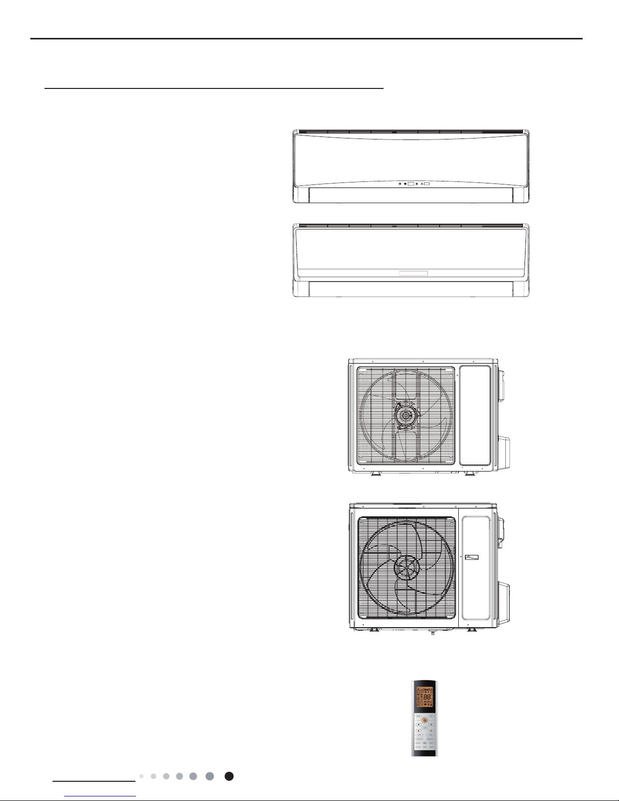
1. Summary
Indoor Unit:
Part
Ⅰ
: Technical Information
Outdoor Unit:
GWH24TD-S3DNA1D/O
GWH18TC-S3DNA1D/O
GWH18TC-S3DNA1D/I
GWH24TD-S3DNA1D/I
GWH18TC-S3DNA2D/I
Remote Controller:
YAC1FB
2
Technical Information
Service Manual
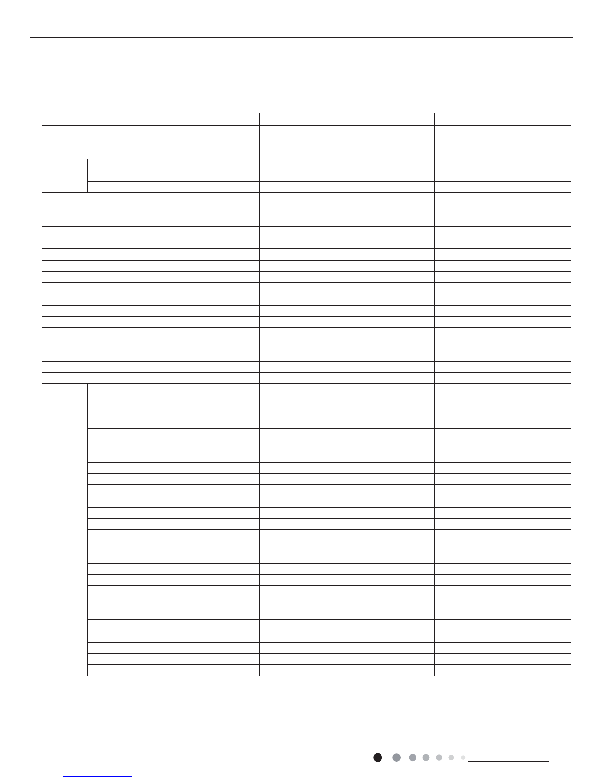
Model
GWH18TC-S3DNA1D GWH18TC-S3DNA2D
Product Code
CB148008603
CB148008605
CB148008604
CB411003103
Power
Supply
Rated Voltage
V~ 220-240 220-240
Rated Frequency
Hz 50/60 50/60
Phases
1 1
Power Supply Mode
Outdoor Outdoor
Cooling Capacity (Min~Max)
W 5300(1000~6300) 5300(1000~6300)
Heating Capacity (Min~Max)
W 5400(1000~6800) 5400(1000~6800)
Cooling Power Input (Min~Max)
W 1514(400~2450) 1514(400~2450)
Heating Power Input (Min~Max)
W 1450(400~2500) 1450(400~2500)
Cooling Current Input
A 8.75 8.75
Heating Current Input
A 8.54 8.54
Rated Input
W 2500 2500
Rated Cooling Current
A 13.7 13.7
Rated Heating Current
A 14.0 14.0
Air Flow Volume(SH/H/MH/M/ML/L/SL)
m3/h 950/870/790/710/630/560/480 950/870/790/710/630/560/480
Dehumidifying Volume
L/h 1.8 1.8
EER
W/W 3.5 3.5
COP
W/W 3.7 3.7
SEER
6.4 6.4
HSPF
/ /
Application Area
m
2
23-34 23-34
Indoor Unit
Indoor Unit Model
GWH18TC-S3DNA1D/I GWH18TC-S3DNA2D/I
Indoor Unit Product Code
CB148N08603
CB148N08605
CB148N08604
CB411N03103
Fan Type
Cross-ow Cross-ow
Fan Diameter Length(DXL)
mm Φ100X765 Φ100X765
Cooling Speed(SH/H/MH/M/ML/L/SL)
r/min 1250/1150/1050/950/850/750/650 1200/1150/1050/950/850/750/650
Heating Speed(SH/H/MH/M/ML/L/SL)
r/min 1300/1200/1100/1000/900/800/700 1350/1200/1100/1000/900/800/700
Fan Motor Power Output
W 25 25
Fan Motor RLA
A 0.1 0.1
Fan Motor Capacitor
μF / /
Evaporator Form
Aluminum Fin-copper Tube Aluminum Fin-copper Tube
Evaporator Pipe Diameter
mm Φ7 Φ7
Evaporator Row-n Gap
mm 2-1.5 2-1.5
Evaporator Coil Length (LXDXW)
mm 765X25.4X342.9 765X25.4X342.9
Swing Motor Model
MP28VC/MP24AA MP28VC/MP24AA
Swing Motor Power Output
W 2/1.5 2/1.5
Fuse Current
A 3.15 3.15
Sound Pressure Level(SH/H/MH/M/ML/L/SL)
dB (A) 46/44/42/40/38/36/34 46/44/42/40/38/36/34
Sound Power Level
(SH/H/MH/M/ML/L/SL)
dB (A) 58/56/54/52/50/48/46 58/56/54/52/50/48/46
Dimension (WXHXD)
mm 1018X319X230 1018X319X230
Dimension of Carton Box (LXWXH)
mm 1094X394X325 1094X394X325
Dimension of Package (LXWXH)
mm 1097X397X340 1097X397X340
Net Weight
kg 14 14
Gross Weight
kg 17 17
2. Specications
2.1 Specication Sheet
3
Service Manual
Technical Information
The above data is subject to change without notice; please refer to the nameplate of the unit.
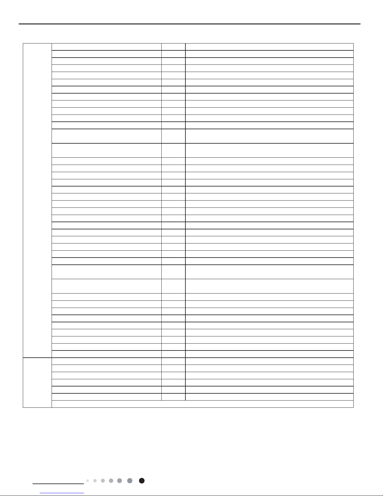
Outdoor
Unit
Outdoor Unit Model
GWH18TC-S3DNA1D/O
Outdoor Unit Product Code
CB148W08600
Compressor Manufacturer
ZHUHAI LANDA COMPRESSOR CO.,LTD
Compressor Model
QXA-B141zF030A
Compressor Oil
68EP
Compressor Type
Rotary
Compressor LRA.
A 25
Compressor RLA
A 7.2
Compressor Power Input
W 1440
Compressor Overload Protector
1NT11L-6233
Throttling Method
Electron expansion valve
Set Temperature Range °C
16~30
Cooling Operation Ambient Temperature
Range
°C
-15~43
Heating Operation Ambient Temperature
Range
°C
-20~24
Condenser Form
Aluminum Fin-copper Tube
Condenser Pipe Diameter
mm Φ9.52
Condenser Rows-n Gap
mm 2-1.4
Condenser Coil Length (LXDXW)
mm 812.5X44X660
Fan Motor Speed
rpm 800
Fan Motor Power Output
W 60
Fan Motor RLA
A 0.58
Fan Motor Capacitor
μF /
Outdoor Unit Air Flow Volume
m3/h 3200
Fan Type
Axial-ow
Fan Diameter
mm Φ520
Defrosting Method
Automatic Defrosting
Climate Type
T1
Isolation
I
Moisture Protection
IP24
Permissible Excessive Operating Pressure
for the Discharge Side
MPa 4.3
Permissible Excessive Operating Pressure
for the Suction Side
MPa 2.5
Sound Pressure Level (H/M/L)
dB (A) 56/-/-
Sound Power Level (H/M/L)
dB (A) 65/-/-
Dimension (WXHXD)
mm 955X700X396
Dimension of Carton Box (LXWXH)
mm 1026X455X735
Dimension of Package (LXWXH)
mm 1029X458X750
Net Weight
kg 47.5
Gross Weight
kg 52
Refrigerant
R410A
Refrigerant Charge
kg 1.6
Connection
Pipe
Connection Pipe Length
m 5
Connection Pipe Gas Additional Charge
g/m 50
Outer Diameter Liquid Pipe
mm Φ6
Outer Diameter Gas Pipe
mm Φ16
Max Distance Height
m 10
Max Distance Length
m 25
Note: The connection pipe applies metric diameter.
4
Technical Information
Service Manual
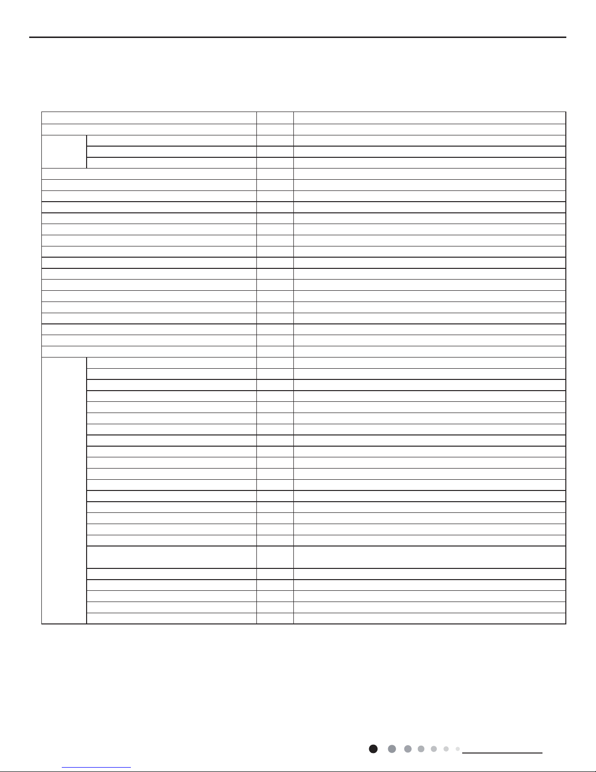
Model
GWH24TD-S3DNA1D
Product Code
CB148008703 CB148008704
Power
Supply
Rated Voltage
V~ 220-240
Rated Frequency
Hz 50/60
Phases
1
Power Supply Mode
Outdoor
Cooling Capacity (Min~Max)
W 7000(2000~8600)
Heating Capacity (Min~Max)
W 7300(1900~9000)
Cooling Power Input (Min~Max)
W 2000(450~3200)
Heating Power Input (Min~Max)
W 1960(380~3200)
Cooling Current Input
A 8.9
Heating Current Input
A 9.63
Rated Input
W 3200
Rated Cooling Current
A 13.3
Rated Heating Current
A 14.2
Air Flow Volume(SH/H/MH/M/ML/L/SL)
m3/h 1200/1130/1060/990/920/850/780
Dehumidifying Volume
L/h 2.5
EER
W/W 3.5
COP
W/W 3.7
SEER
6.3
HSPF
/
Application Area
m
2
32-50
Indoor Unit
Indoor Unit Model
GWH24TD-S3DNA1D/I
Indoor Unit Product Code
CB148N08703 CB148N08704
Fan Type
Cross-ow
Fan Diameter Length(DXL)
mm Φ106X890
Cooling Speed(SH/H/MH/M/ML/L/SL)
r/min 1400/1300/1200/1100/1000/850/750
Heating Speed(SH/H/MH/M/ML/L/SL)
r/min 1400/1300/1200/1100/1000/850/750
Fan Motor Power Output
W 60
Fan Motor RLA
A 0.24
Fan Motor Capacitor
μF /
Evaporator Form
Aluminum Fin-copper Tube
Evaporator Pipe Diameter
mm Φ7
Evaporator Row-n Gap
mm 2-1.5
Evaporator Coil Length (LXDXW)
mm 903X25.4X381
Swing Motor Model
MP35CJ/MP24HB/MP24HC
Swing Motor Power Output
W 2.5/1.5/1.5
Fuse Current
A 3.15
Sound Pressure Level(SH/H/MH/M/ML/L/SL)
dB (A) 51/50/46/44/42/40/37
Sound Power Level
(SH/H/MH/M/ML/L/SL)
dB (A) 65/62/58/56/54/52/49
Dimension (WXHXD)
mm 1178X326X264
Dimension of Carton Box (LXWXH)
mm 1253X411X349
Dimension of Package (LXWXH)
mm 1256X414X364
Net Weight
kg 17
Gross Weight
kg 21

5
Service Manual
Technical Information
The above data is subject to change without notice; please refer to the nameplate of the unit.
Outdoor
Unit
Outdoor Unit Model
GWH24TD-S3DNA1C/O
Outdoor Unit Product Code
CB148W08700
Compressor Manufacturer
ZHUHAI LANDA COMPRESSOR CO,LTD.
Compressor Model
QXAS-D23zX090A
Compressor Oil
FV50S
Compressor Type
Rotary
Compressor LRA.
A 25
Compressor RLA
A 11.5
Compressor Power Input
W 2550
Compressor Overload Protector
1NT11L-6233
Throttling Method
Electron expansion valve
Set Temperature Range °C
16~30
Cooling Operation Ambient Temperature
Range
°C
-15~43
Heating Operation Ambient Temperature
Range
°C
-20~24
Condenser Form
Aluminum Fin-copper Tube
Condenser Pipe Diameter
mm Φ7.94
Condenser Rows-n Gap
mm 3-1.4
Condenser Coil Length (LXDXW)
mm 960X87.15X748
Fan Motor Speed
rpm 820
Fan Motor Power Output
W 90
Fan Motor RLA
A 0.28
Fan Motor Capacitor
μF /
Outdoor Unit Air Flow Volume
m3/h 4000
Fan Type
Axial-ow
Fan Diameter
mm Φ552
Defrosting Method
Automatic Defrosting
Climate Type
T1
Isolation
I
Moisture Protection
IP24
Permissible Excessive Operating Pressure
for the Discharge Side
MPa 4.3
Permissible Excessive Operating Pressure
for the Suction Side
MPa 2.5
Sound Pressure Level (H/M/L)
dB (A) 58/-/-
Sound Power Level (H/M/L)
dB (A) 68/-/-
Dimension (WXHXD)
mm 980X790X427
Dimension of Carton Box (LXWXH)
mm 1080X485X840
Dimension of Package (LXWXH)
mm 1083X488X855
Net Weight
kg 65
Gross Weight
kg 70
Refrigerant
R410A
Refrigerant Charge
kg 2.3
Connection
Pipe
Connection Pipe Length
m 5
Connection Pipe Gas Additional Charge
g/m 50
Outer Diameter Liquid Pipe
mm Φ6
Outer Diameter Gas Pipe
mm Φ16
Max Distance Height
m 10
Max Distance Length
m 25
Note: The connection pipe applies metric diameter.
6
Technical Information
Service Manual
Capacity ratio(%)
Outdoor Temp.(°C)
0
20
40
60
80
100
120
31 33 35 37 39 41 43 45 47
• Conditions
Indoor: DB27°C/WB19°C
Indoor air flow:Super High
Pipe length: 5m
Capacity ratio(%)
Outdoor Temp.(°C)
20
40
60
80
100
120
-20-15 -10-5
051
0
• Conditions
Indoor: DB20°C/WB15°C
Indoor air flow:Super High
Pipe length: 5m
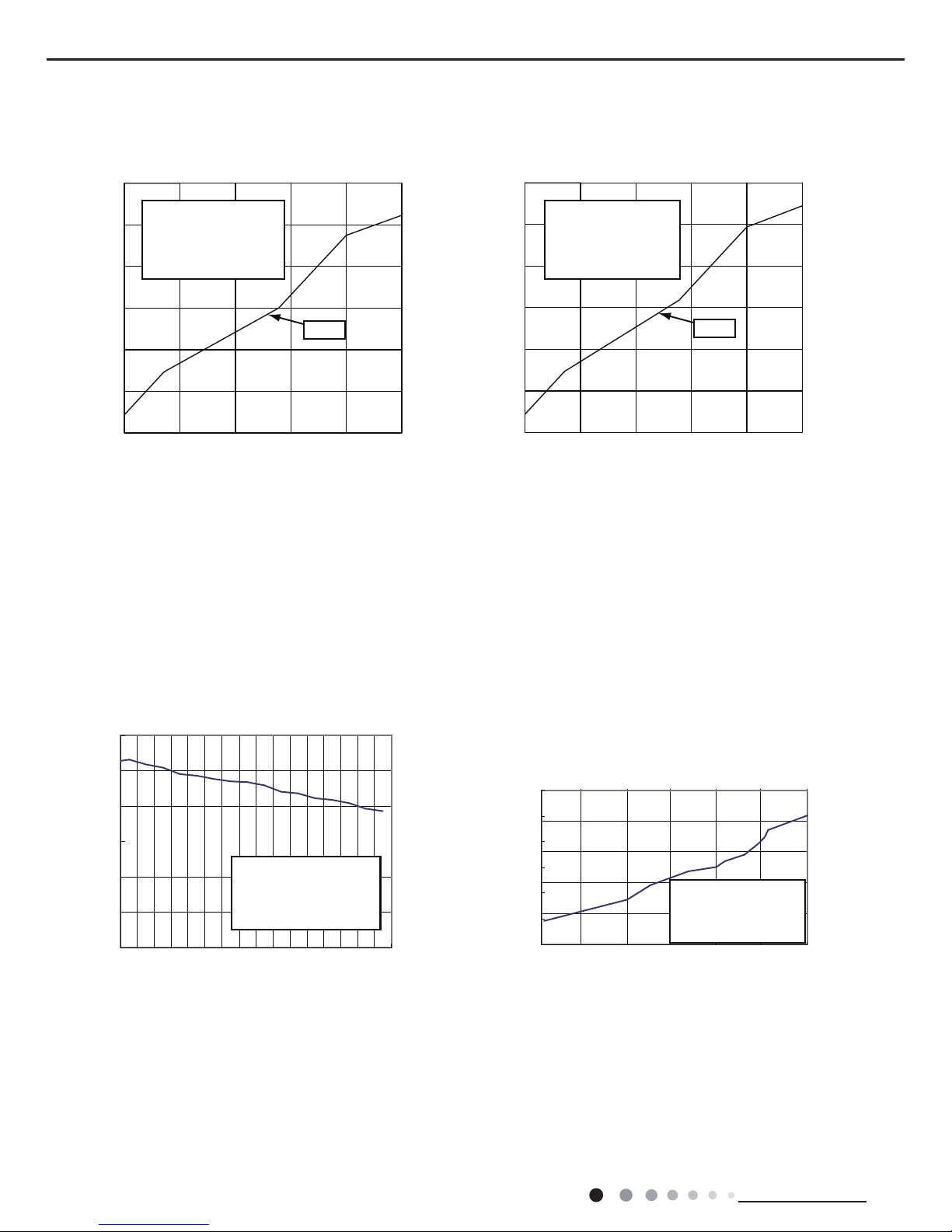
2.2 Operation Characteristic Curve
2.3 Capacity Variation Ratio According to Temperature
Cooling: Heating:
Current(A)
Compressor Speed (rps)
12010080604020
Compressor Speed (rps)
Current(A)
13
11
9
7
5
3
1
120
10080604020
13
11
9
7
5
3
1
• Conditions
Indoor: DB27°C/WB19°C
Outdoor: DB35°C/WB24°C
Indoor air flow: High
Pipe length: 5m
• Conditions
Indoor: DB20°C/WB15°C
Outdoor: DB7°C/WB6°C
Indoor air flow: High
Pipe length: 5m
230V
230V
Cooling:
Heating:
7
Service Manual
Technical Information
2.5 Cooling and Heating Data Sheet in Rated Frequency
Rated cooling
condition(°C)
(DB/WB)
Model
Pressure of gas pipe
connecting indoor and
outdoor unit
Inlet and outlet pipe
temperature of heat
exchanger
Fan speed of
indoor unit
Fan speed of
outdoor unit
Compressor
revolution
(rps)
Indoor Outdoor P (MPa) T1 (°C) T2 (°C)
27/19 35/24 All models 0.9~1.0
in:8~11
out:11~14
in:75~83
out:37~48
Super High High 75
Rated heating
condition(°C)
(DB/WB)
Model
Pressure of gas pipe
connecting indoor and
outdoor unit
Inlet and outlet pipe
temperature of heat
exchanger
Fan speed of
indoor unit
Fan speed of
outdoor unit
Compressor
revolution
(rps)
Indoor Outdoor P (MPa) T1 (°C) T2 (°C)
20/15 7/6 All models 2.2~2.4
in:75~83
out:37~45
in:1~3
out:2~6
Super High High 75
Instruction:
T1: Inlet and outlet pipe temperature of evaporator
T2: Inlet and outlet pipe temperature of condenser
P: Pressure at the side of big valve
Connection pipe length: 5 m.
Cooling:
Heating:
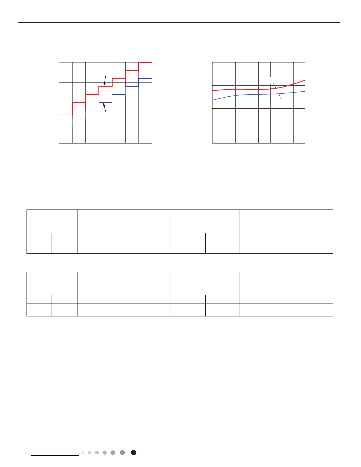
2.4 Noise Curve
46
48
50
52
54
56
58
60
20 30 40 50 60 70 80 90
100
Compressor frequency(Hz)
Noise dB(A)
Heating
24K
Cooling
18K
30
35
40
45
50
SL LMLMMH HSH
Indoor fan motor rating speed
Noise/dB(A)
Indoor side noise Outdoor side noise
8
Technical Information
Service Manual
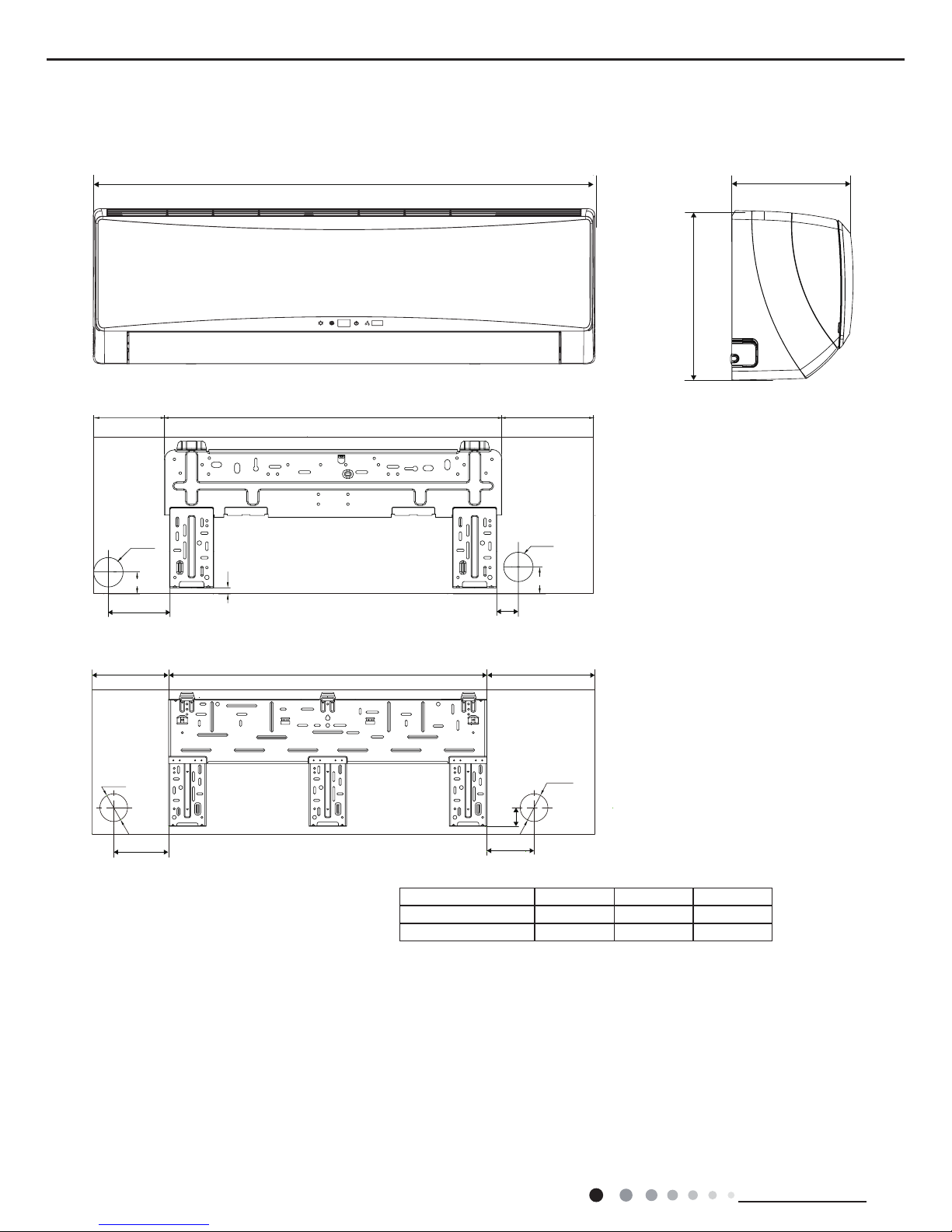
3. Outline Dimension Diagram
3.1 Indoor Unit
Unit:mm
Model W H D
18K 1018 319 230
24K 1178 326 264
130
100
50
178 747
253
Φ70
Φ70
144
685
189
55
44
Φ70
13
55
Φ70
119
W
H
D
18K
24K
9
Service Manual
Technical Information
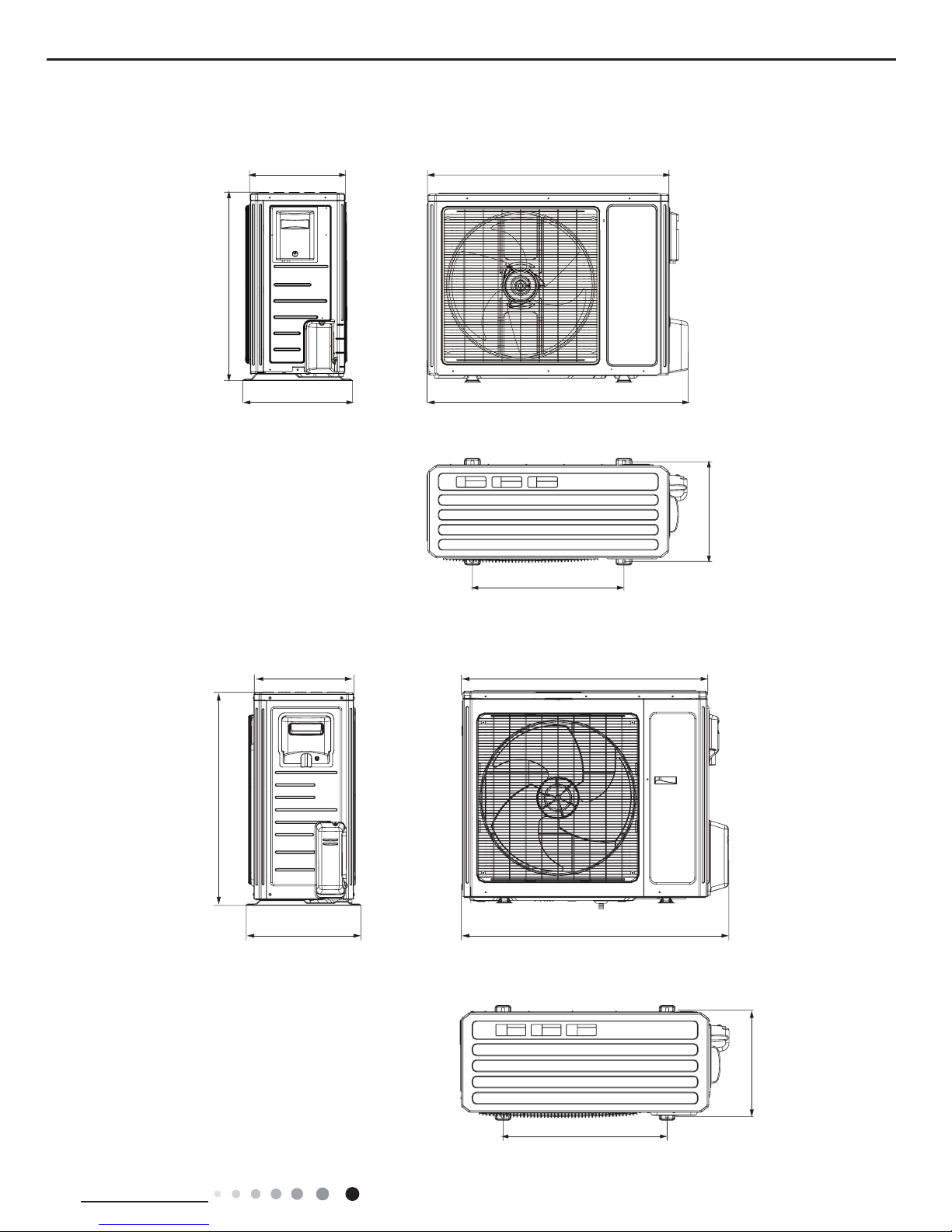
3.2 Outdoor Unit
955
890340
396
364
700
560
Unit:mm
Unit:mm
920
980
427
370
790
610
395
GWH24TD-S3DNA1D/O
GWH18TC-S3DNA1D/O
10
Technical Information
Service Manual
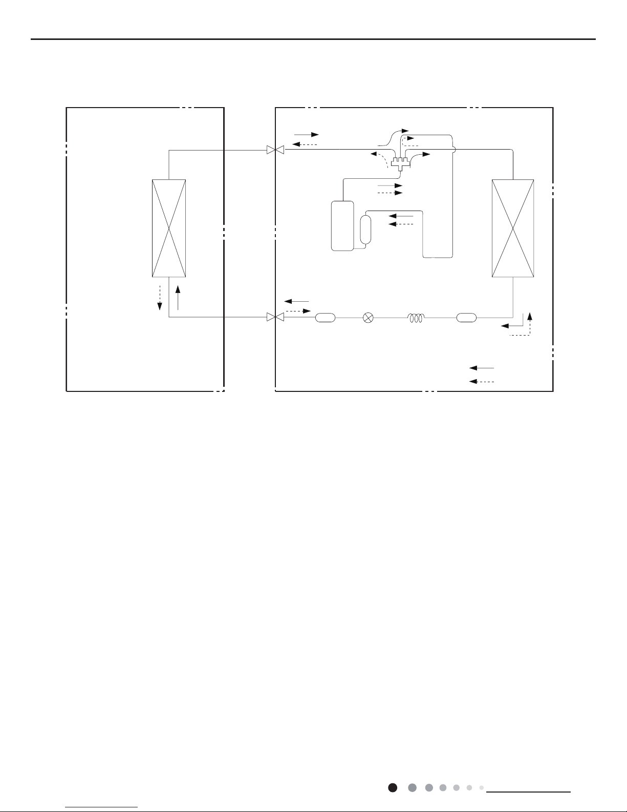
4. Refrigerant System Diagram
Indoor unit
Outdoor unit
COOLING
HEATING
4-Way valve
Discharge
Suction
Heat
exchanger
(evaporator)
Heat
exchanger
(condenser)
Valve
Valve
Liquid pipe
side
Gas pipe
side
Strainer
Strainer
Electron
expansion
valve
Capillary
Connection pipe specication:
Liquid pipe:1/4" (6mm)
Gas pipe:5/8" (16mm)
11
Service Manual
Technical Information
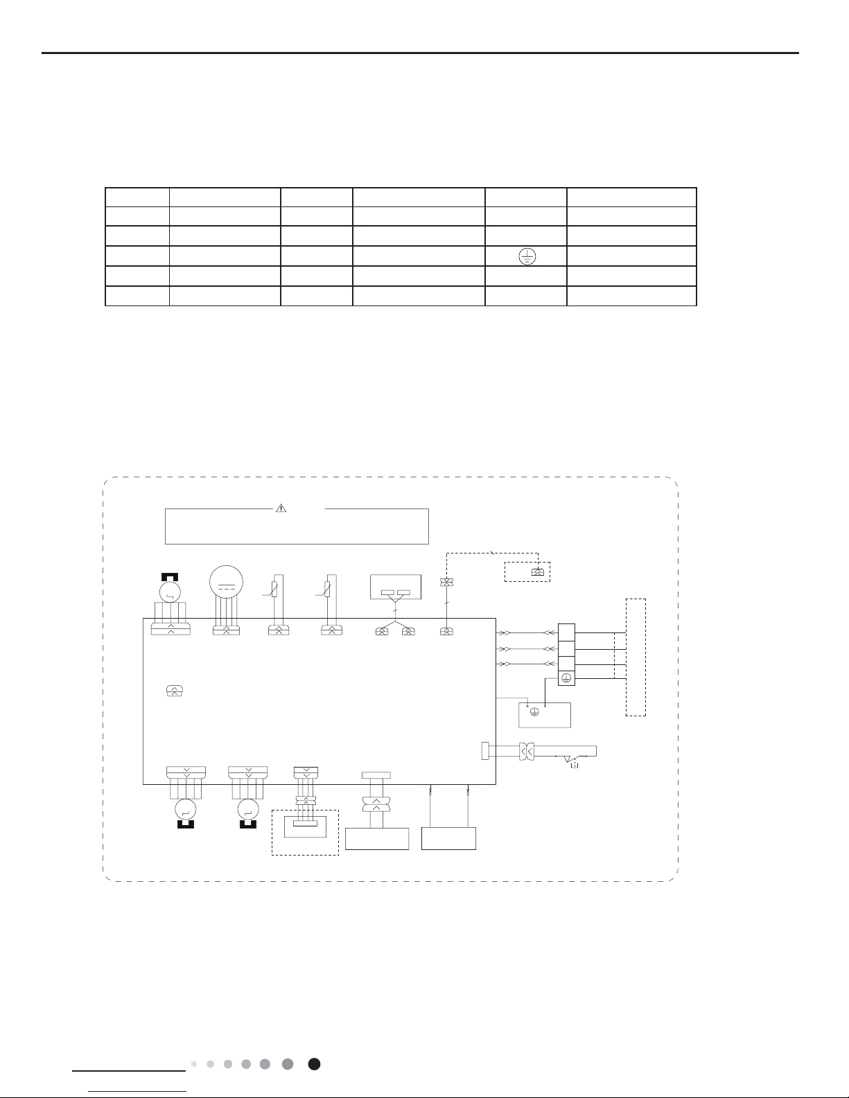
5. Electrical Part
5.1 Wiring Diagram
● Indoor Unit
●Instruction
Symbol Symbol Color Symbol Symbol Color Symbol Name
WH White GN Green CAP Jumper cap
YE Yellow BN Brown COMP Compressor
RD Red BU Blue Grounding wire
YEGN Yellow/Green BK Black / /
VT Violet OG Orange / /
Note: Jumper cap is used to determine fan speed and the swing angle of horizontal lover for this model.
GWH18TC-S3DNA1D/I GWH18TC-S3DNA2D/I
UP-DOWNUP-DOWN
M4
M3
SWING-UD2SWING-UD1
AP2
CAP
JUMP
CONNECTOR
CLEAN
ELECTROSTATIC
DEDUSTING
YEGN
BN
BK
BU
GENERATOR
6361000023204
COLD PLASMA
WH
BK
CONNECTOR
PE
BLOCK
TERMINAL
RD BU
HEALTH-L HEALTH-N
PRINTED CIRCUIT BOARD
X10
SWITCH
SA
C.
X2
NO.
3
2
N(1)
CONNECTING
CABLE
X1
EVAPORATOR
AC-L
N
COM-OUT
XT1
YEGN
YEGN
PE
OUTDOOR UNIT
Please don't touch any electronic component or terminal
when the machine is running,stopping or has been powered
off for less than 3 minutes to prevent electric shock !
STEPPING
MOTOR
STEPPING
MOTOR
COM-INNER1
WIFI MODULE
WIFI
AP4
CONNECTOR
BN
BK
BU
WARNING
CONNECTOR
DC-MOTOR
θθ
DISPLAY BOARD
RECEIVER AND
RT1
RT2
TEMP.SENSOR
ROOM TUBE
TEMP.SENSOR
FAN MOTOR
TUBEROOM
M1
DISP1DISP2
AP1
SWING-LR
M2
LEFT-RIGHT
STEPPING MOTOR
Wired Controller
AP3
12
Technical Information
Service Manual
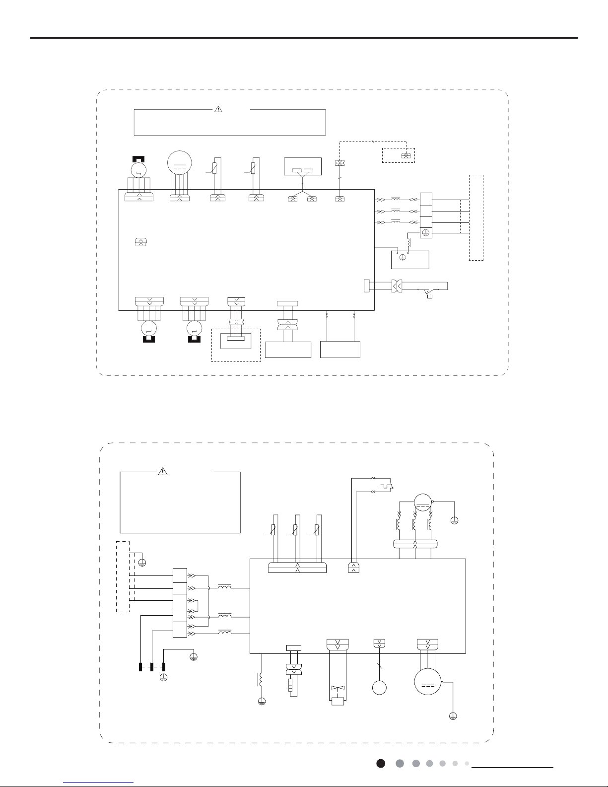
● Outdoor Unit
GWH18TC-S3DNA1D/O
Please don't touch any
terminal when the voltage
of terminal P(DC+) and
N(DC-) at AP1 is higher
than 30V to prevent the
risk of electric shock !
WARNING
COM_INNER
N1
AC_L
RD
BAND
HEATER
BOTTOM
RD
EH
HEAT_B
NL
YEGN
BU
PE
N
L
N(1)
2
3
BN
BK
BU
XT
INDOOR UNIT
L1
RING
BK
BN
BU
BN
BU
YEGN
BLOCK
TERMINAL
PE
MAGNETIC
L1
L1
POWER
6361000021801
BN
L3
PRINTED CIRCUIT BOARD
PE
YEGN
FAN MOTOR
4WAY OFANFA
VTVT
VALVE
4YV
4-WAY
M1
PE
EKV
Electronic
Expansion
Valve
PE
YEGN
PE
AP1
T_SENSOR
W(RD)V(YE)U(BU)
OVC_COMP
15K 50K20K
θ
θ
θ
COMP.
W
V
U
L2 L2
RING
MAGNETIC
L2
OVERLOAD PROTECTOR
YEGN
YEBU
RD
PE
PE
RT1 RT2 RT3
RD
WHWH
SAT
COMP
X1
YEBU
WH BK
TEMP.SENSOR
OUTTUBE
OUTROOM
TEMP.SENSOR
EXHAUST
TEMP.SENSOR
GWH24TD-S3DNA1D/I
UP-DOWNUP-DOWN
M4
M3
SWING-UD2SWING-UD1
AP2
CAP
JUMP
CONNECTOR
CLEAN
ELECTROSTATIC
DEDUSTING
YEGN
BN
BK
BU
GENERATOR
6361000023208
COLD PLASMA
WH
BK
CONNECTOR
PE
BLOCK
TERMINAL
RD BU
HEALTH-L HEALTH-N
PRINTED CIRCUIT BOARD
X10
SWITCH
SA
C.
X2
NO.
3
2
N(1)
CONNECTING
CABLE
X1
BU
BK
BN
EVAPORATOR
AC-L
N
COM-OUT
XT1
YEGN
YEGN
PE
OUTDOOR UNIT
Please don't touch any electronic component or terminal
when the machine is running,stopping or has been powered
off for less than 3 minutes to prevent electric shock !
STEPPING
MOTOR
STEPPING
MOTOR
CONNECTOR
COM-INNER1
DC-MOTOR
θθ
DISPLAY BOARD
RECEIVER AND
RT1
RT2
TEMP.SENSOR
ROOM TUBE
TEMP.SENSOR
FAN MOTOR
TUBEROOM
M1
DISP1DISP2
AP1
SWING-LR
M2
LEFT-RIGHT
STEPPING MOTOR
Wired Controller
AP3
WIFI MODULE
WIFI
AP4
CONNECTOR
L1
L1
L1
L1
WARNING
13
Service Manual
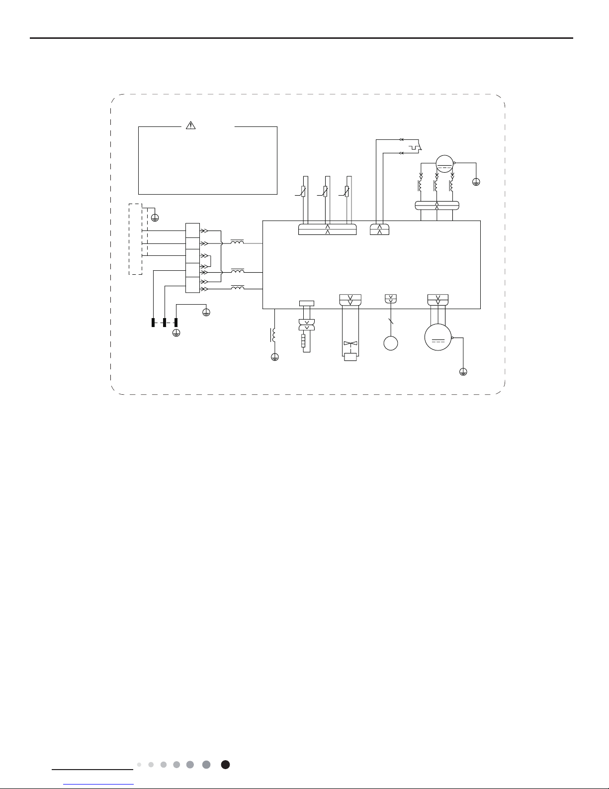
Technical Information
GWH24TD-S3DNA1D/O
Please don't touch any
electronic component or
terminal when the machine is
running , stopping or has
been powered off for less
than 30 minutes to prevent
the risk of electric shock !
WARNING
COM-INNER
N1
AC_L
NL
YEGN
BU
PE
N
L
N(1)
2
3
BN
BK
BU
XT
INDOOR UNIT
L1
RING
BK
BN
BU
BN
BU
BLOCK
TERMINAL
MAGNETIC
L1
L1
POWER
6361000007501
BN
T-SENSOR
θ
θ
θ
COMP.
L3
W
V
U
PRINTED CIRCUIT BOARD
PE
YEGN
FAN MOTOR
4WAY OFANFA
VTVT
VALVE
4YV
4-WAY
M1
PE
EKV
Electronic
Expansion
Valve
PE
YEGN
PE
L2 L2
RING
MAGNETIC
L2
OVERLOAD PROTECTOR
YEGN
W(RD)V(YE)U(BU)
YEBU
RD
PE
PE
RT1 RT2 RT3
RD
OVC-COMP
WHWH
SAT
COMP
X1
YEBU
WH BK
TEMP.SENSOR
OUTTUBE
OUTROOM
TEMP.SENSOR
EXHAUST
TEMP.SENSOR
AP1
HEAT-B
EH
RD
BOTTOM
HEATER
BAND
RD
50K15K20K
YEGN
PE
The above data is subject to change without notice. Please refer to the nameplate of the unit.
14
Technical Information
Service Manual
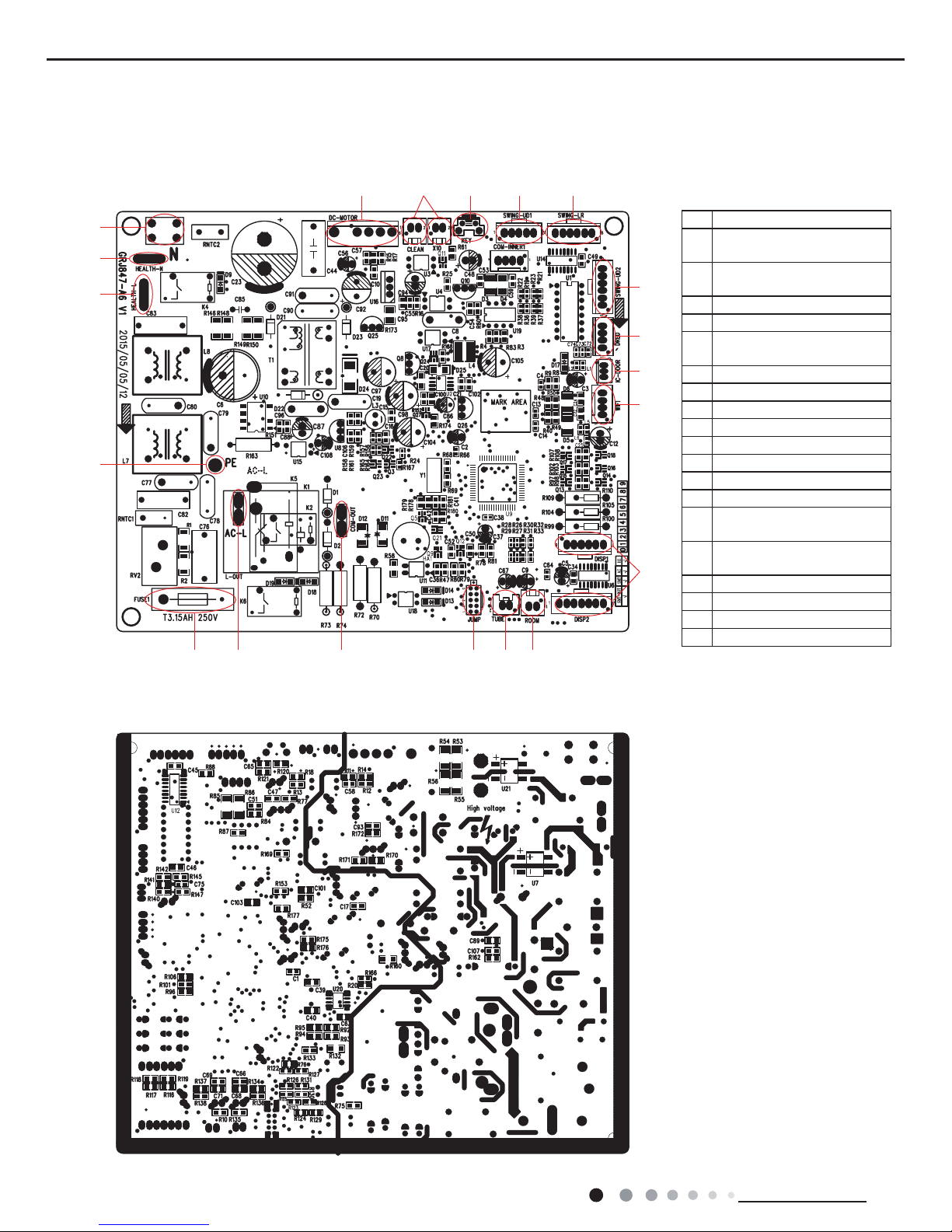
5.2 PCB Printed Diagram
● Top view
● Bottom view
Indoor Unit
1
2
3
4
5 6 7 8 9
10
11
12
13
14
151617181920
1 Grounding wire
2
Interface of health function
live wire
3
Interface of health function
neutral wire
4 Neutral wire
5 Interface of DC motor
6
Interface of electrostatuc
dedusting
7 Auto button
8 Up&down swing interface 1
9 eft&right swing interface
10 Up&down swing interface 2
11 Interface of DRED
12 Interface of IC-DOOR
13 Interface of WiFi
14 Display interface
15
Interface of ambient
temperature sensor
16
Interface of tube temperature
sensor
17 Jumper cap
18 Communication interface
19 Live wire interface
20 Fuse
15
Service Manual
Technical Information
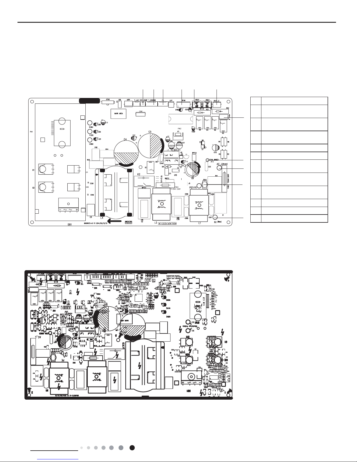
● Top view
● Bottom view
Outdoor Unit
18K
No. Name
1
Terminal of compressor
overload protection
2
Terminal of temperature
sensor
3
Terminal of electronic
expansion valve
4
Terminal of outdoor fan
5
Terminal of 4-way valve
6
Terminal of
compressorelectric heating
7
Terminal of chassis electric
heating
8
Terminal of indoor unit and
outdoor unit communication
9
Power supply live wire
10
Earthing wire
11
Power supply neutral wire
12345
6
7
8
9
10
11
16
Technical Information
Service Manual
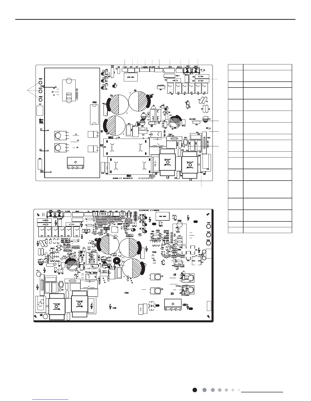
● Top view
● Bottom view
24K
No. Name
1
Power supply neutral
wire
2Power supply live wire
3
Communication wire
with indoor unit
4
Terminal of outdoor
temperature sensor
5
Terminal of compressor
overload protection
6
Terminal of electronic
expansion valve
7Terminal of outdoor fan
8
Terminal of compressor
electric heating
9Terminal of 4-way valve
10
Terminal of compressor
wire
11
Terminal of chassis
electric heating
12
Terminal of low ambient
temperature cooling
temperature sensor
13
Terminal of high
pressure protection
14
Terminal of low pressure
protection
15 Te rminal of 2-way valve
16 Earthing wire
1
10
2
16
3
11
15987654141312
17
Service Manual
Technical Information
6. Function and Control
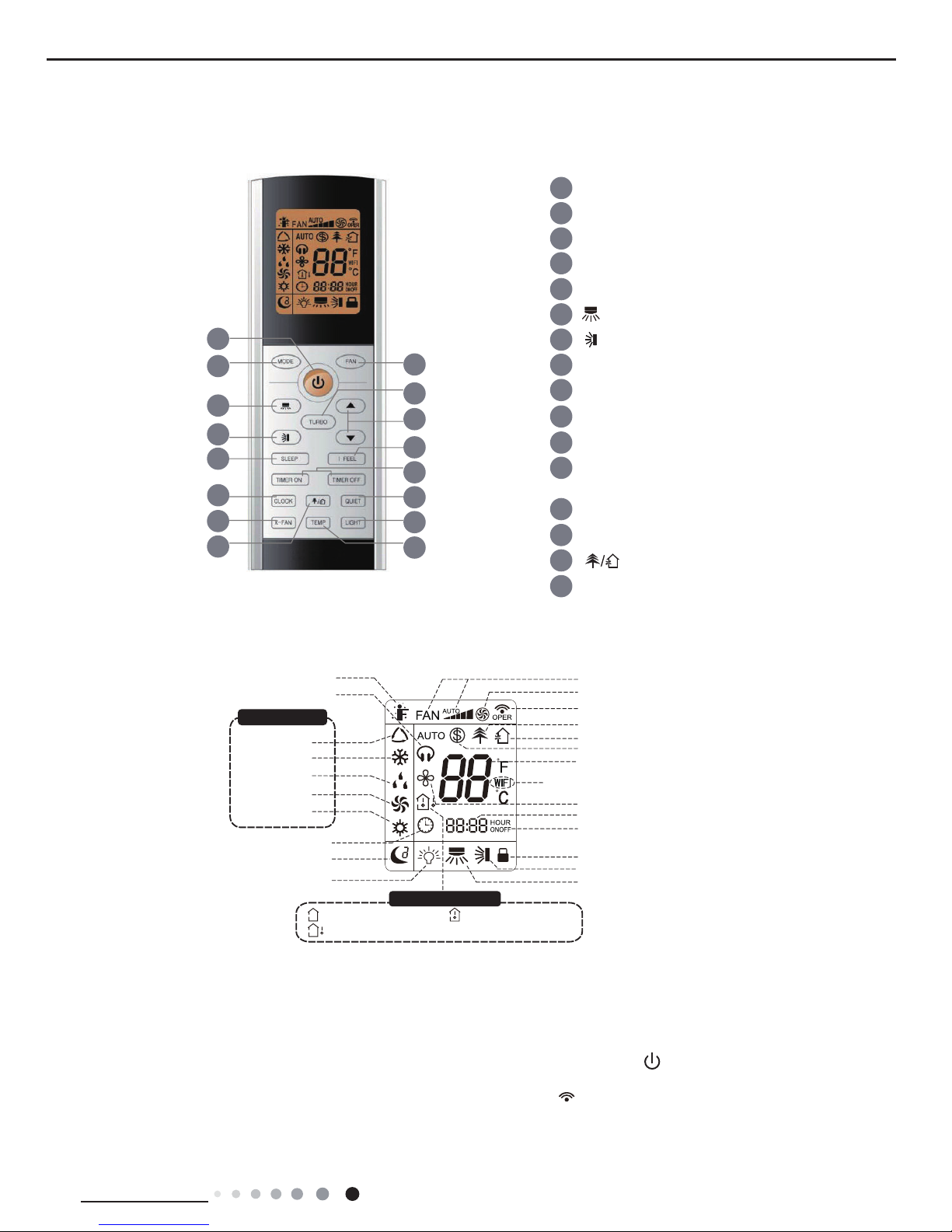
6.1 Remote Controller Introduction
Buttons on Remote Controller
Introduction for icons on display screen
Introduction for buttons on remote controller
Note:
● After putting through the power, the air conditioner will give out a sound. Operation indictor " " is ON (red indicator). After that,
you can operate the air conditioner by using remote controller.
●
Under on status, pressing the button on the remote controller, the signal icon " "
on the display of remote controller will blink once
and the air conditioner will give out a “de” sound, which means the signal has been sent to the air conditioner.
6
3
7
9
11
13
15
12
14
16
10
8
5
4
2
1
1
ON/OFF button
2 MODE button
3 FAN button
4 TURBO button
6
button
7 button
9 I FEEL button
14 LIGHT button
15 button
16 TEMP button
11 CLOCK button
12
QUIET button(This function is unavailable for this
model)
13 X-FAN button
10 TIMER ON / TIMER OFF button
8 SLEEP button
5 ▲/ button
▲
Send signal
Turbo mode
8℃ heating function
Set temperature
Set time
X-FAN function
WiFi
TIMER ON /TIMER OFF
Child lock
Up & down swing
Left & right swing
Set fan speed
Light
Temp. display type
:Set temp.
:Outdoor ambient temp.
:Indoor ambient temp.
Sleep mode
Clock
Heat mode
Fan mode
Dry mode
Cool mode
Auto mode
Operation mode
I feel
Healthy mode
Scavenging functions
Quiet
18
Technical Information
Service Manual
1. ON/OFF button
2. MODE button
3. FAN button
Press this button can turn on or turn off the air conditioner. After turning on the air conditioner, operation indicator " "on indoor unit’s
display is ON (green indicator. The colour is different for different models), and indoor unit will give out a sound.
● When selecting auto mode, air conditioner will operate automatically according to sensed temperature. Set temperature can’t be adjusted
and will not be displayed as well. Press "FAN" button can adjust fan speed. Press " " / " " button can adjust fan blowing angle.
● After selecting cool mode, air conditioner will operate under cool mode. Cool indicator " "on indoor unit is ON. Press "▲" or " ▲ "
button to adjust set temperature. Press "FAN" button to adjust fan speed. Press " " / " " button to adjust fan blowing angle.
● When selecting dry mode, the air conditioner operates at low speed under dry mode. Dry indicator " " on indoor unit is ON. Under dry
mode, fan speed can’t be adjusted. Press " " / " " button to adjust fan blowing angle.
● When selecting fan mode, the air conditioner will only blow fan, no cooling and no heating. All indicators are OFF, Operation indicator is
ON.Press "FAN" button to adjust fan speed. Press " " / " " button to adjust fan blowing angle.
● When selecting heating mode, the air conditioner operates under heat mode. Heat indicator " " on indoor unit is ON. Press "▲" or " ▲
" button to adjust set temperature. Press "FAN" button to adjust fan speed. Press " " / " " button to adjust fan blowing angle. (Cooling
only unit won’t receive heating mode signal. If setting heat mode with remote controller, press ON/OFF button can’t start up the unit.
Note:
● For preventing cold air, after starting up heating mode, indoor unit will delay 1~5 minutes to blow air (actual delay time is depend on indoor
ambient temperature).
● Set temperature range from remote controller: 16~30℃(61-86°F); Fan speed: auto, low speed, medium speed, high speed.
4. TURBO button
Under COOL or HEAT mode, press this button to turn to quick COOL or quick HEAT mode. " " icon is displayed on remote controller.
Press this button again to exit turbo function and " " icon will disappear. If start this function, the unit will run at super-high fan speed to
cool or heat quickly so that the ambient temp. approachs the preset temp. as soon as possible.
5. ▲/▲ button
6. button
● Press " ▲ " or " ▲ " button once increase or decrease set temperature 1℃(°F). Holding " ▲ " or " ▲ " button, 2s later, set temperature
on remote controller will change quickly. On releasing button after setting is finished, temperature indicator on indoor unit will change
accordingly. (Temperature can’t be adjusted under auto mode)
● When setting TIMER ON, TIMER OFF or CLOCK, press " ▲ " or " ▲ " button to adjust time. (Refer to CLOCK, TIMER ON, TIMER OFF
buttons) When setting TIMER ON, TIMER OFF or CLOCK, press " ▲ " or " ▲ " button to adjust time. (Refer to CLOCK, TIMER ON, TIMER
OFF buttons)
Press this button can select left & right swing angle. Fan blow angle can be selected
circularly as below:
Note:
● Press this button continuously more than 2s, the main unit will swing back and forth from left to right, and then loosen the button, the unit
will stop swinging and present position of guide louver will be kept immediately.
Note:
● Under AUTO speed, air conditioner will select proper fan speed automatically according to sensed temperature.
● Fan speed under dry mode is low speed.
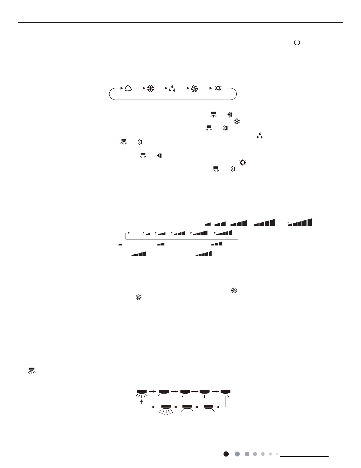
This button is used for setting Fan Speed in the sequence that goes from AUTO, , , , to then back
to Auto.
Press this button to select your required operation mode.
AUTO COOL FA NDRY HEAT
Auto
Medium spee
d
Low-Medium speedLow speed
High speedMedium-High speed
no display
(stops at current position)
19
Service Manual
Technical Information
● Under swing left and right mode, when the status is switched from off to , if press this button again 2s later, status will switch to off
status directly; if press this button again within 2s, the change of swing status will also depend on the circulation sequence stated above.
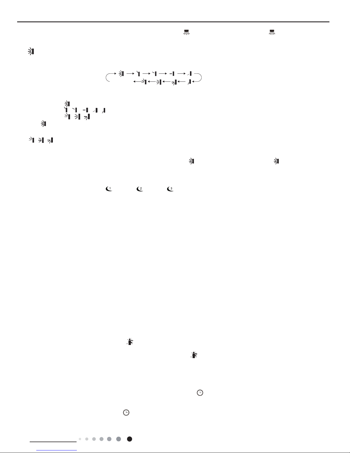
7. button
Press this button can select up & down swing angle. Fan blow angle can be selected
circularly as below:
● When selecting " ", air conditioner is blowing fan automatically. Horizontal louver will automatically swing up & down at maximum angle.
● When selecting " 、 、 、 、 ", air conditioner is blowing fan at xed position. Horizontal louver will stop at the xed position.
● When selecting " 、 、 " , air conditioner is blowing fan at xed angle. Horizontal louver will send air at the xed angle.
● Hold " "button above 2s to set your required swing angle. When reaching your required angle, release the button.
Note:
● " 、 、 " may not be available. When air conditioner receives this signal, the air conditioner will blow fan automatically.
● Press this button continuously more than 2s, the main unit will swing back and forth from up to down, and then loosen the button, the unit
will stop swinging and present position of guide louver will be kept immediately.
● Under swing up and down mode, when the status is switched from off to , if press this button again 2s later, status will switch to off
status directly; if press this button again within 2s,the change of swing status will also depend on the circulation sequence stated above.
no display
(horizontal louvers stops
at current position)
8. SLEEP button
Press this button, can select Sleep 1 ( ), Sleep 2 ( ), Sleep 3 ( ) and cancel the Sleep, circulate between these, after electried, Sleep
Cancel is defaulted.
Sleep 1 is Sleep mode 1, in Cool modes; sleep status after run for one hour, the main unit setting temperature will increase 1 ℃ , two hours,
setting temperature increased 2 ℃, then the unit will run at this setting temperature; In Heat mode: sleep status after run for one hour, the
setting temperature will decrease 1 , two hours, setting temperature will decrease 2℃ , then the unit will run at this setting temperature.
● Sleep 2 is sleep mode 2, that is air conditioner will run according to the presetting a group of sleep temperature curve.
● Sleep 3-the sleep curve setting under Sleep mode by DIY;
(1)Under Sleep 3 mode, press “Turbo” button for a long time, remote controller enters into user individuation sleep setting status, at this time,
the time of remote controller will display “1hour”, the setting temperature “88” will display the corresponding temperature
of last setting sleep curve and blink (The rst entering will display according to the initial curve setting value of original factory);
(2)Adjust “+” and “-” button, could change the corresponding setting temperature, after adjusted, press “Turbo” button for conrmation;
(3) At this time, 1hour will be automatically increased at the timer postion on the remote control, (that are "2hours" or "3hours" or "8hours"),
the place of setting temperature "88" will display the corresponding temperature of last setting sleep curve and blink;
(4) Repeat the above step (2)~(3) operation, until 8 hours temperature setting nished,sleep,curve setting nished, at this time, the remote
controller will resume the original timer display; temperature display will resume to original setting temperature.
● Sleep3- the sleep curve setting under Sleep mode by DIY could be inquired:
The user could accord to sleep curve setting method to inquire the presetting sleep curve, enter into user individuation sleep setting status,
but do not change the temperature, press “Turbo” button directly for conrmation. Note: In the above presetting or enquiry procedure, if
continuously within 10s, there is no button pressed, the sleep curve setting within 10s, there is no button pressed, the sleep curve setting
status will be automatically quit and resume to display the original displaying. In the presetting or enquiry procedure, press "ON/OFF" button,
"Mode" button, "Timer" button or "Sleep" button, the sleep curve setting or enquiry status will quit similarly.
9. I FEEL button
10. TIMER ON / TIMER OFF button
Press this button to start I FEEL function and " " will be displayed on the remote controller. After this function is set, the remote controller
will send the detected ambient temperature to the controller and the unit will automatically adjust the indoor temperature according to the
detected temperature. Press this button again to close I FEEL function and " " will disappear.
● Please put the remote controller near user when this function is set. Do not put the remote controller near the object of high temperature
or low temperature in order to avoid detecting inaccurate ambient temperature.
● TIMER ON button
"TIMER ON" button can set the time for timer on. After pressing this button, " " icon disappears and the word "ON" on remote controller
blinks. Press " ▲ " or " ▲ "button to adjust TIMER ON setting. After each pressing " ▲ " or " ▲ " button, TIMER ON setting will increase
or decrease 1min. Hold " ▲ " or " ▲ " button, 2s later, the time will change quickly until reaching your required time. Press "TIMER ON" to
conrm it. The word "ON" will stop blinking. " " icon resumes displaying. Cancel TIMER ON: Under the condition that TIMER ON is started
up, press "TIMER ON" button to cancel it.
20
Technical Information
Service Manual
12. QUIET button(This function is unavailable for this model)
13. X-FAN button
14. LIGHT button
16. TEMP button
15. button(This function is unavailable for this model)
Press this button, the Quiet status is under the Auto Quiet mode (display " " and "AUTO" signal ) and Quiet mode (display " " singal)
and Quiet OFF (there is no signal of " " displayed), after powered on, the Quiet OFF is defaulted.
Note:
●
The Quiet function cannot be set up in Fan and Dry mode; Under the Quiet mode,
the fan speed is not available.
● If Auto Quiet mode has been selected, after the room temperature reached the setting temperature or 10mins later, the AC will immediately
enter into the Quiet running status, at this time the fan speed is not adjustable.
Pressing this button in COOL or DRY mode, the icon " " is displayed and the indoor fan will continue operation for 2 minutes in order to
dry the indoor unit even though you have turned off the unit. After energization, X-FAN OFF is defaulted.
X-FAN is not available in AUTO, FAN or HEAT mode.This function indicates that moisture on evaporator of indoor unit will be blowed after
the unit is stopped to avoid mould.
● Having set X-FAN function on: After turning off the unit by pressing ON/OFF button indoor fan will continue running for about 2 minutes. at
low speed. In this period, press X-FAN button to stop indoor fan directly.
● Having set X-FAN function off: After turning off the unit by pressing ON/OFF button, the complete unit will be off directly.
Press this button to turn off display light on indoor unit. " " icon on remote controller disappears. Press this button again to turn on
display light. " " icon is displayed.
By pressing this button, you can see indoor set temperature, indoor ambient temperature or outdoor ambient temperature on indoor unit’s
display. The setting on remote controlleris selected circularly as below:
Press this button to achieve the on and off of healthy and scavenging functions in operation status. Press this button for the rst time to start
scavenging function; LCD displays " ". Press the button for the second time to start healthy and scavenging functions simultaneously;
LCD displays " " and " " . Press this button for the third time to quit healthy and scavenging functions simultaneously. Press the button
for the fourth t ime to start healthy function; LCD display " " . Press this button again to repeat the operation above.
no display
11. CLOCK button
Press this button to set clock time. " " icon on remote controller will blink. Press " ▲ " or " ▲ " button within 5s to set clock time. Each
pressing of " ▲ " or " ▲ " button, clock time will increase or decrease 1 minute. If hold " ▲ " or " ▲ " button, 2s later, time will change quickly.
Release this button when reaching your required time. Press "CLOCK" button to conrm the time. " " icon stops blinking.
Note:
● Clock time adopts 24-hour mode.
● The interval between two operation can’t exceeds 5s. Otherwise, remote controller will quit setting status. Operation for TIMER ON/TIMER
OFF is the same.
● TIMER OFF button
"TIMER OFF" button can set the time for timer off. After pressing this button," "icon disappears and the word "OFF" on remote controller
blinks. Press " ▲ " or " ▲ " button to adjust TIMER OFF setting. After each pressing " ▲ " or " ▲ " button, TIMER OFF setting will increase
or decrease 1min. Hold " ▲ " or " ▲ " button, 2s later, the time will change quickly until reaching your required time. Press "TIMER OFF"
word "OFF" will stop blinking. " " icon resumes displaying. Cancel TIMER OFF. Under the condition that TIMER OFF is started up, press
"TIMER OFF" button to cancel it.
Note:
● Under on and off status, you can set TIMER OFF or TIMER ON simultaneously.
● Before setting TIMER ON or TIMER OFF, please adjust the clock time.
● After starting up TIMER ON or TIMER OFF, set the constant circulating valid. After that, air conditioner will be turned on or turned off
according to setting time. ON/OFF button has no effect on setting. If you don’t need this function, please use remote controller to cancel it.

21
Service Manual
Technical Information
1. Energy-saving function
Under cooling mode, press "TEMP" and " CLOCK" buttons simultaneously to start up or turn off energy-saving function. When energy-saving
function is started up, "SE" will be shown on remote controller, and air conditioner will adjust the set temperature automatically according to
ex-factory setting to reach to the best energy-saving effect. Press "TEMP" and "CLOCK"buttons simultaneously again to exit energy-saving
function.
Note:
● Under energy-saving function, fan speed is defaulted at auto speed and it can’t be adjusted.
●
Under energy-saving function, set temperature can’t be adjusted. Press "TURBO"
button and the remote controller won’t send signal.
● Sleep function and energy-saving function can’t operate at the same time. If energy-saving function has been set under cooling mode,
press sleep button will cancel energy-saving function. If sleep function has been set under cooling mode, start up the energy-saving function
will cancel sleep function.
● When selecting " " or no display with remote controller, temperature indicator on indoor unit displays set temperature.
● When selecting " " with remote controller, temperature indicator on indoor unit displays indoor ambient temperature.
● When selecting " " with remote controller, temperature indicator on indoor unit displays outdoor ambient temperature.
Note:
●
Outdoor temperature display is not available for some models. At that time, indoor
unit receives " "signal, while it displays indoor set
temperature.
● It’s defaulted to display set temperature when turning on the unit.There is no display in the remote controller.
● Only for the models whose indoor unit has dual-8 display.
● When selecting displaying of indoor or outdoor ambient temperature, indoor temperature indicator displays corresponding temperature and
automatically turn to display set temperature after three or ve seconds.
Function introduction for combination buttons
2. 8℃ heating function(only for the mode with this function)
3. Child lock function
4. Temperature display switchover function
5.Combination "MODE" and "TURBO" buttons:About WIFI function
Under heating mode, press "TEMP" and "CLOCK" buttons simultaneously to start
up or turn off 8℃ heating function. When this function is
started up, " " and "8℃" will be shown on remote controller, and the air conditioner keep the heating status
at 8℃. Press "TEMP" and
"CLOCK" buttons simultaneously again to exit 8℃heating function.
Note:
● Under 8℃ heating function, fan speed is defaulted at auto speed and it can’t be adjusted.
● Under 8℃ heating function, set temperature can’t be adjusted. Press "TURBO" button and the remote controller won’t send signal.
● Sleep function and 8℃ heating function can’t operate at the same time. If 8℃heating function has been set under cooling mode, press
sleep button will cancel 8℃ heating function. If sleep function has been set under cooling mode, start up the 8℃ heating function will cancel
sleep function.
● Under ℉ temperature display, the remote controller will display 46℉ heating.
Press " ▲ " and " ▲ " simultaneously to turn on or turn off child lock function. When child lock function is on, " " icon is displayed on
remote controller. If you operate the remote controller, the " " icon will blink three times without sending signal to the unit.
Under OFF status, press " ▲ " and "MODE" buttons simultaneously to switch temperature display between ℃ and ℉.
Press "MODE" and "TURBO" button simultaneously to turn on or turn off WIFI function. When WIFI function is turned on, the "
WIFI"
icon will
be displayed on remote controller; Long press "MODE" and "TURBO" buttons simultaneously for 10s, remote controller will send WIFI reset
code and then the WIFI function will be turned on. WIFI function is defaulted ON after energization of the remote controller.
Operation guide
1.
After putting through the power, press "ON/OFF" button on remote controller to turn on the air conditioner.
2.
Press "MODE" button to select your required mode: AUTO, COOL, DRY, FAN, HEAT.
3.
Press " ▲ " or " ▲ " button to set your required temperature. (Temperature can’t be adjusted under auto mode).
4.
Press "FAN" button to set your required fan speed: auto, low, medium and high speed.
5.
Press "SWING" button to select fan blowing angle.
22
Technical Information
Service Manual
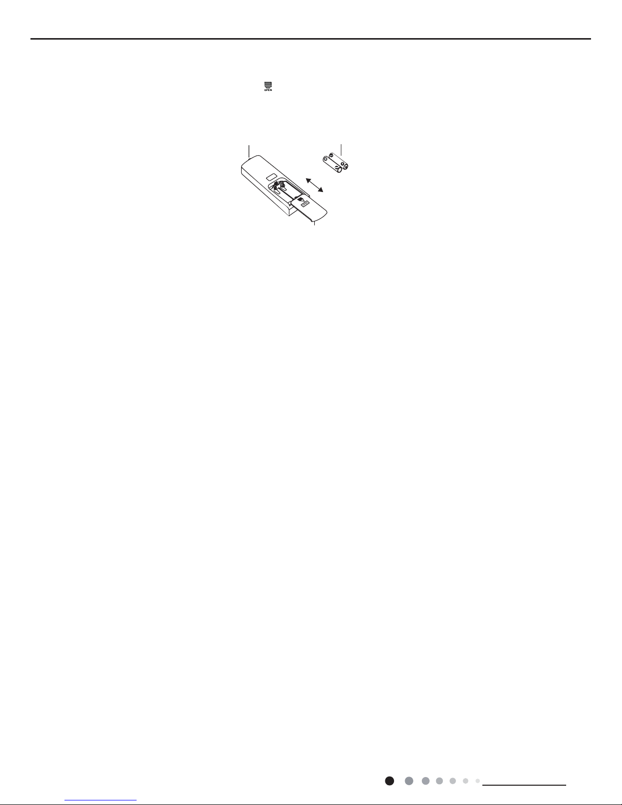
Replacement of batteries in remote controller
1. Press the back side of remote controller marked with " ", as shown in the g, and then push out
the cover of battery box along the
arrow direction.
2. Replace two 7# (AAA 1.5V) dry batteries, and make sure the position of "+" polar and "-" polar are correct.
3. Reinstall the cover of battery box.
Note:
● During operation, point the remote control signal sender at the receiving window on indoor unit.
● The distance between signal sender and receiving window should be no more than 8m, and there should be no obstacles between
them.
● Signal may be interfered easily in the room where there is uorescent lamp or wireless telephone; remote controller should be close to
indoor unit during operation.
● Replace new batteries of the same model when replacement is required.
● When you don’t use remote controller for a long time, please take out the batteries.
● If the display on remote controller is fuzzy or there’s no display, please replace batteries.
signal sender battery
Cover of battery box
remove
reinstall
23
Service Manual
Technical Information
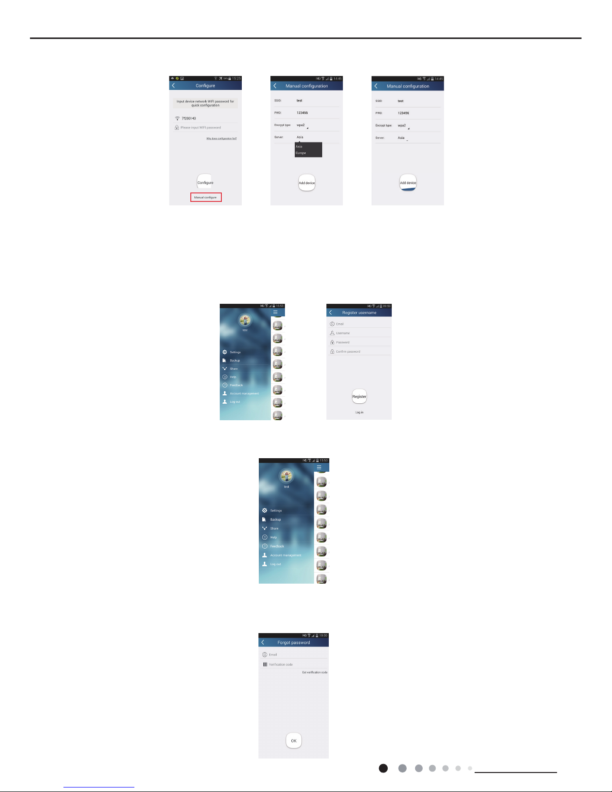
2.Short-distance and long-distance control setting for air conditioner connecting
Step 1: Under short-distance control, return to the homepage "Home Control". Tap at the top right corner of the homepage
"Home control". Select "Add device"
Step 2: Enter the correct network name and password, select the encrypt mode ""wpa2" and select the server,then tap the button
"Add device" for conguration. If conguration succeeds, App will notify user that conguration is successful and return to homepage.
6.2 Operation of Smart Control (Smart Phone, Tablet PC)
Operation Instructions
Download and install APP
Scan the following QR code (also indicated on package box) with your smart phone and download Wi Smart.
Conguration
Before operation, please nish the following conguration in order to realize Wi control and the connection between air conditioner and
mobile phone.
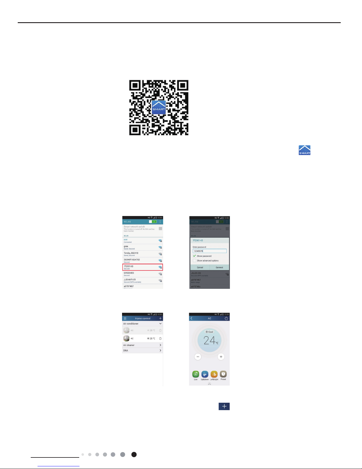
1.Short-distance control setting for air conditioner using wi hotspot
Step 1: Air conditioner wi is set to AP mode in factory. You can search the air conditioner wi hotspot through your smart phone. The
name of wi hotspot is the last 8 numbers of the air condtioner mac address. Password is 12345678.
Step 2: Open Gree APP and the screen will show the air conditioner that you just connected. Click this air conditioner to enter and
realize short-distance control, as shown below. Please refer to "Functions introduction" for specic control methods.
Install the APP according to its guidance. When successfully installed, your smart phone homepage will show this icon
24
Technical Information
Service Manual
Functions introduction
1.User registration
Purpose: To realize long-distance control
Operation instruction: For the rst time login, you have to register a new username. If you already have a username, skip the registration
step and enter email address and password on the "Login Page" to log in. If password is forgotton, you can reset the password.
Operation steps:
(1) Account login: Slide the page "Home c ontrol". and enter the page "Menu" on the left. Tap "Login" to enter the page "Register
username". New user must rst register a username. Tap "Register”.
(2) Enter your email address and tap "Get verication code". Wait until you receive the verication code. Enter the code and then tap
"OK" to log in. Username will appear. As shown here, the username is "test".
(3) If password is forgotten, you can reset the password with your email address.T
ap "Forgot password" and enter the page "Forgot password". Tap "Verification code" to get a email verification code. Enter a new
password and tap "OK" to log in.
Please note:
Please select the encrypt mode "empty" if your wi has been set without password.
25
Service Manual
Technical Information
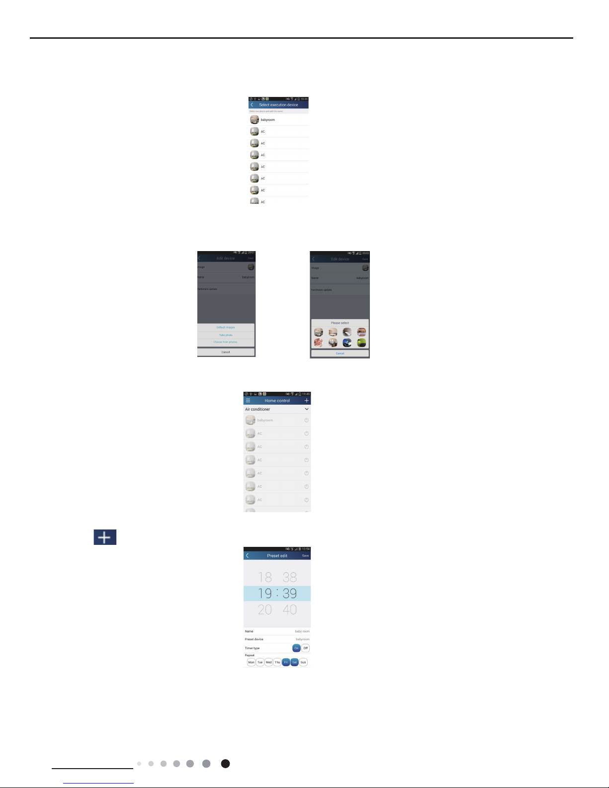
2.Personal setting
Purpose: Set name (device name, preset name, etc.) and images (device image) in order to identify a user easily.
(1) Set device name
After quick conguration, a list of controllable smart devices will be generated. Default name for air conditioner is "AC".
Step 1: Tap and hold "babyroom" to enter the page "Edit device". Tap "Image" to select the source of image. Select from "Default images"
or "Take photo" or "Choose from photos" and save an image.
Step 2: Tap "Name" to change device name. Save it and the new device name will be shown.
name will be shown.
(2) Set preset name
Step 1: Tap at the top right corner of the homepage "Home control". Select "Add preset" and enter the page "Preset edit".
Step 2: Choose the time. Tap "Name". As shown in the picture, its name is "baby room". For timer type, select "On". Then select the
repeating days. Save the setting of preset name.
26
Technical Information
Service Manual
(3) Set device image
Please refer to step 1 in 2(1)
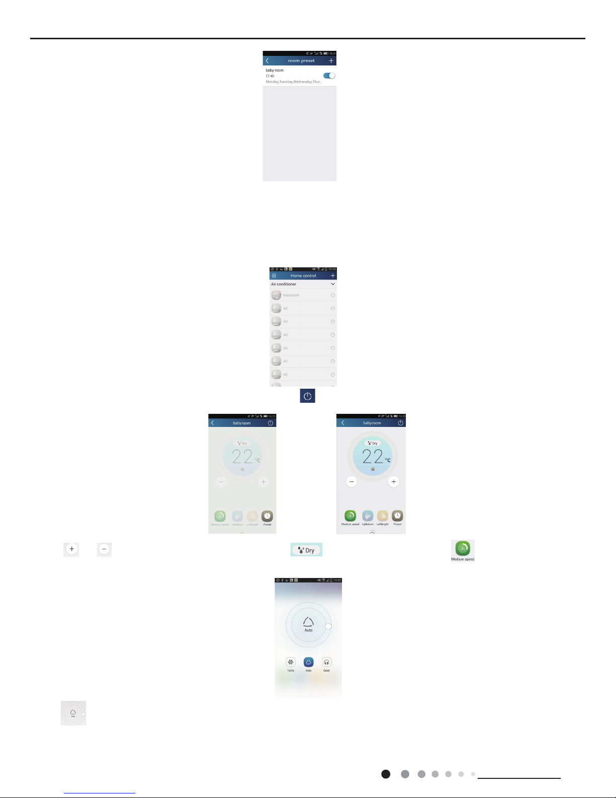
3.Control functions
(1) Common control functions: General control on the operation of smart devices (On/Off, temperature, fan speed, mode, etc.) and the
setting of advanced functions (air exchange, dry, health, light, sleep, energy saving upper limit).
Step 1: General control Enter the homepage "Home control" rst. Take "baby home" as an example.
Tap "babyroom" and enter the page of air conditioner control. Tap to turn on the control switch.
Tap or to increase or decrease temperature. Tap to change working mode. Tap to enter the page of fan
speed adjustment.
Tap and go around the circle to adjust fan speed.
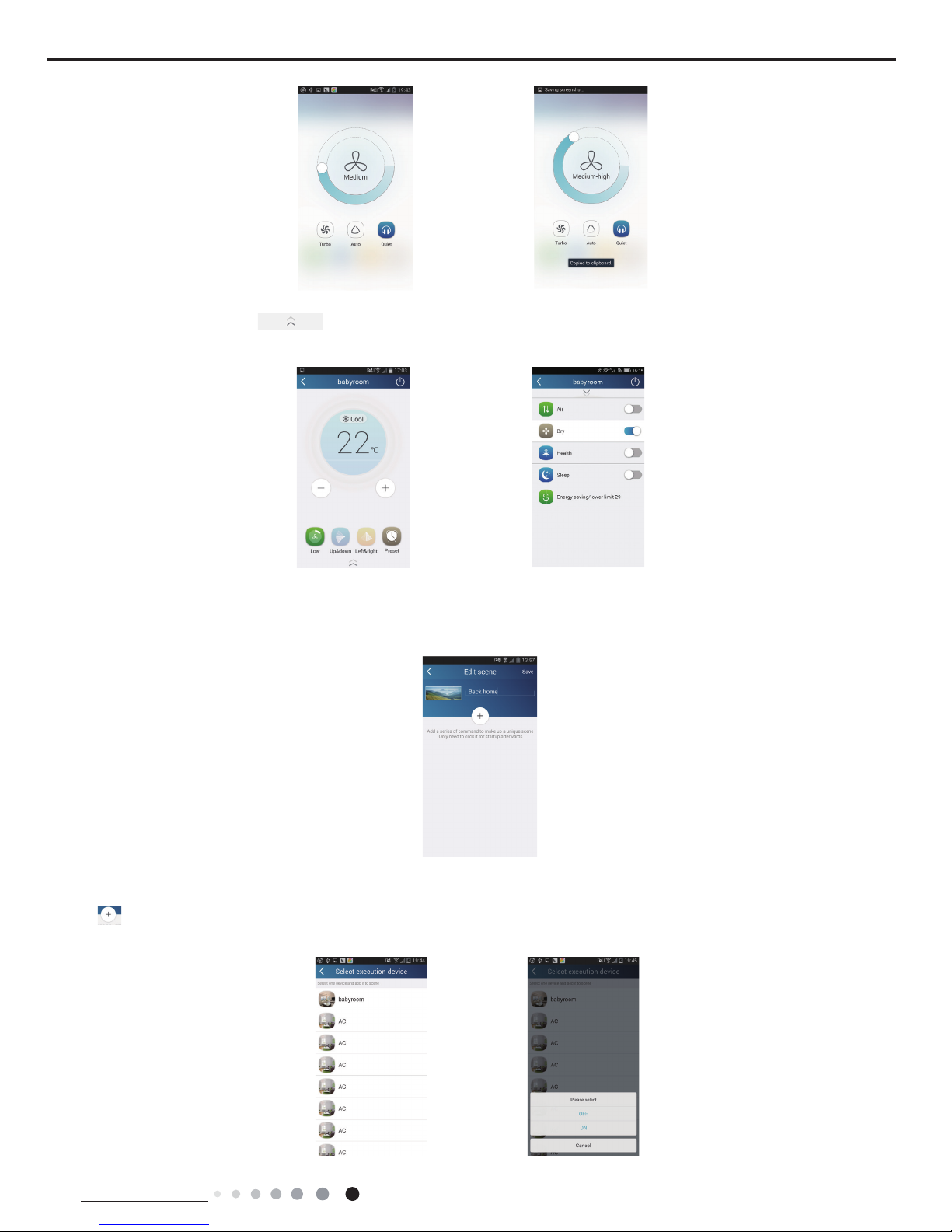
27
Service Manual
Technical Information
Step 2: Advanced settings Tap to enter advanced settings. You mayselect "Air", "Dry", "Health", "Light", "Sleep" or "Energy
saving".
(2) Advanced control functions: Set scene; Preset; Link: Infrared control (only applicable to smart phone with infrared emitter)
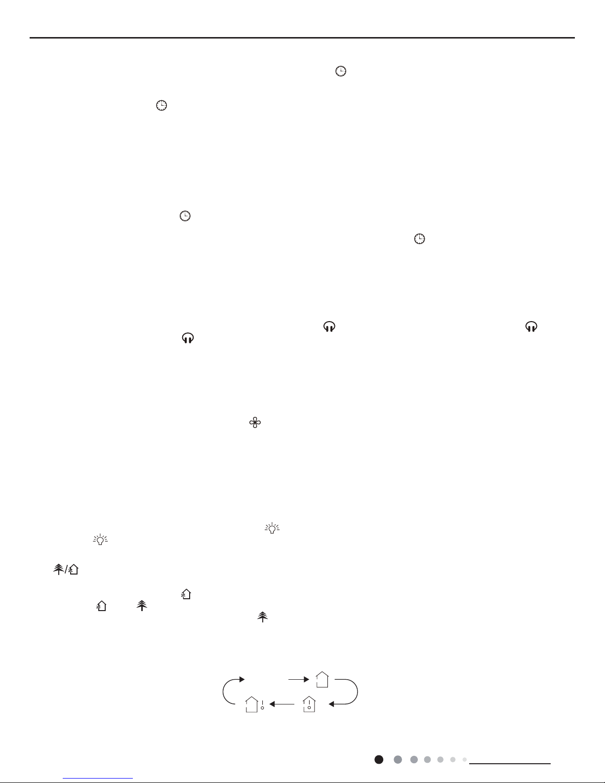
Set scene: Preset the operation of several smart devices by one tap. On the page "Home control", tap the image of "Home control" to enter
the page "Edit scene".
Tap "Add scene" and edit the scene name, for example, "Back home". Add execution devices.
Tap to add commands. On the page "Select execution device", select the air conditioner named "babyroom". Then select "ON" or
"OFF".
 Loading...