

Gree GWH18MC-K3DNA7E, GWH18MC-K3DNA3E, GWH18MC-3DNA7E, GWH18MC-K3DNA8E, GWH18MC-K3DNB3E Service Manual
...
GREE ELECTRIC APPLIANCES INC.OF ZHUHAI
Service Manual
Models:GWH18MC-K3DNA2E
GWH18MC-K3DNA3E
GWH18MC-K3DNA4E
GWH18MC-K3DNA5E
GWH18MC-K3DNA7E
GWH18MC-K3DNA7E
(Electric heating belt)
GWH18MC-K3DNA8E
GWH18MC-K3DNB3E
GWH18MC-K3DNB7E
GWH18MC-K3DNC1E
GWH18MC-K3DNC3E
GWH18MC-K3DNE4E
GWH24MD-K3DNA2E
GWH24MD-K3DNA3E
GWH24MD-K3DNA4E
GWH24MD-K3DNA5E
GWH24MD-K3DNA7E
GWH24MD-K3DNA7E
(Electric heating belt)
GWH24MD-K3DNA8E
GWH24MD-K3DNB3E
GWH24MD-K3DNC1E
(Refrigerant R410A)

Table of Contents
Summary and Features
...................................................................................... 1
1.Safety Precautions
............................................................................................ 3
2.Specifi cations
........................................................................................................ 4
2.1 Unit Specifi cations
.................................................................................................. 4
2.2 Operation Characteristic Curve
......................................................................... 16
2.3 Capacity Variation Ratio According to Temperature
..................................... 17
2.4 Operation Data
...................................................................................................... 17
2.5 Noise Criteria Curve Tables for Both Models
................................................. 18
3. Construction Views
....................................................................................... 19
3.1 Indoor Unit
.............................................................................................................. 19
3.2 Outdoor Unit
........................................................................................................... 20
4. Refrigerant System Diagram
................................................................. 21
5. Schematic Diagram
....................................................................................... 22
5.1 Electrical Data
........................................................................................................ 22
5.2 Electrical Wiring
.................................................................................................... 22
5.3 Printed Circuit Board
............................................................................................ 25
6. Function and Control
................................................................................... 28
6.1 Remote Control Operations
............................................................................... 28
6.2 Description of Each Control Operation
............................................................ 31
7. Installation Manual
......................................................................................... 38
7.1 Notices for Installation
......................................................................................... 38
7.2 Installation Dimension Diagram
........................................................................ 40
7.3 Install Indoor Unit
.................................................................................................. 41
7.4 Install Outdoor Unit
............................................................................................... 42
7.5 Check After Installation and Test Operation
................................................... 43
7.6 Installation and Maintenance of Healthy Filter
............................................... 44

8. Exploded Views and Parts List
........................................................... 45
8.1 Indoor Unit
............................................................................................................. 45
8.2 Outdoor Unit
.......................................................................................................... 57
9. Troubleshooting
............................................................................................... 65
9.1 Precautions before Performing Inspection or Repair
................................... 65
9.2 Confi rmation
.......................................................................................................... 66
9.3 Flashing LED of Indoor/Outdoor Unit and Primary Judgement
................. 66
9.4 How to Check simply the main part
.................................................................. 71
10. Removal Procedure
.................................................................................... 91
10.1 Removal Procedure of Indoor Unit
................................................................. 91
10.2 Removal Procedure of Outdoor Unit
........................................................... 100

Summary and Features
1
Summary and Features
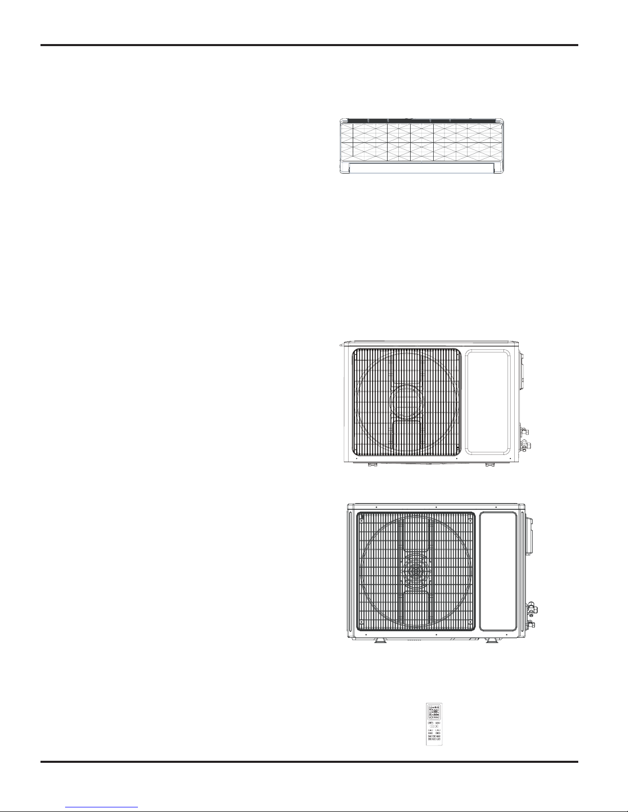
Indoor Unit
GWH18MC-K3DNA2E/I
GWH24MD-K3DNA2E/I
GWH18MC-K3DNA4E/I
GWH24MD-K3DNA4E/I
GWH18MC-K3DNA5E/I
GWH24MD-K3DNA5E/I
GWH18MC-K3DNB3E/I
GWH24MD-K3DNB3E/I
GWH18MC-K3DNC1E/I
GWH24MD-K3DNC1E/I
GWH18MC-K3DNE4E/I
GWH18MC-K3DNA8E/I
GWH24MD-K3DNA8E/I
GWH18MC-K3DNB7E/I
GWH18MC-K3DNC3E/I
GWH18MC-K3DNA3E/I
GWH24MD-K3DNA3E/I
Summary and Features
2
Outdoor Unit
GWH18MC-K3DNA7E/O
GWH18MC-K3DNA7E/O
(Electric heating belt)
GWH24MD-K3DNA7E/O
GWH24MD-K3DNA7E/O
(Electric heating belt)
YB1FA
Remote Controller
GWH18MC-K3DNA7E/I
GWH18MC-K3DNA7E/I
GWH24MD-K3DNA7E/I
GWH24MD-K3DNA7E/I
Safety Precautions
3
Caution
Warning
Warning
Caution
could result in
personal injury
or death.
Incorrect handling
result in
injury
, or damage to product
or property.
Incorrect handling
may
minor
Recognize the following safety information:
Installing, starting up, and servicing air conditioner can be
hazardous due to system pressure, electrical components, and
equipment location, etc.
Only trained, qualified installers and service personnel are
allowed to install, start-up, and service this equipment.
Untrained personnel can perform basic maintenance functions
such as cleaning coils. All other operations should be performed
by trained service personnel.
When handling the equipment, observe precautions in the
manual and on tags, stickers, and labels attached to the equipment. Follow all safety codes. Wear safety glasses and
work gloves. Keep quenching cloth and fire extinguisher nearby
when brazing.
Read the instructions thoroughly and follow all warnings or
cautions in literature and attached to the unit. Consult local
building codes and current editions of national as well as local
electrical codes.
All electric work must be performed by a licensed technician
according to local regulations and the instructions given in this
manual.
Never supply power to the unit unless all wiring and tubing
are completed, reconnected and checked.
This system adopts highly dangerous electrical voltage.
Incorrect connection or inadequate grounding can cause
personal injury or death. Stick to the wiring diagram and all
the instructions when wiring.
Have the unit adequately grounded in accordance with
local electrical codes.
Have all wiring connected tightly. Loose connection may
lead to overheating and a possible fire hazard.
All installation or repair work shall be performed by your dealer
or a specialized subcontractor as there is the risk of fire, electric
shock, explosion or injury.
Make sure the ceiling wall is strong enough to bear the
weight of the unit.
Make sure the noise of the outdoor unit does not disturb
neighbors.
Properly insulate any tubing running inside the room to
prevent the water from damaging the wall.
Make sure the outdoor unit is installed on a stable, level
surface with no accumulation of snow, leaves, or trash
beside.
Follow all the installation instructions to minimize the risk
of damage from earthquakes, typhoons or strong winds.
Avoid contact between refrigerant and fire as it generates
poisonous gas.
Apply specified refrigerant only. Never have it mixed with
any other refrigerant. Never have air remain in the
refrigerant line as it may lead to rupture and other hazards.
Make sure no refrigerant gas is leaking out when
installation is completed.
Should there be refrigerant leakage, the density of
refrigerant in the air shall in no way exceed its limited
value , or it may lead to explosion .
Before installing, modifying, or servicing system, main
electrical disconnect switch must be in the OFF position.
There may be more than 1 disconnect switch. Lock out and
tag switch with a suitable warning label.
Keep your fingers and clothing away from any moving parts.
Clear the site after installation. Make sure no foreign
objects are left in the unit.
Always ensure effective grounding for the unit.
Never install the unit in a place where a combustible gas
might leak, or it may lead to fire or explosion.
Make a proper provision against noise when the unit is
installed at a telecommunication center or hospital.
Provide an electric leak breaker when it is installed in a
watery place.
Never wash the unit with water.
Handle unit transportation with care. The unit should not be
carried by only one person if it is more than 20kg.
Never touch the heat exchanger fins with bare hands.
Never touch the compressor or refrigerant piping without
wearing glove.
Do not have the unit operate without air filter.
Should any emergency occur, stop the unit and disconnect
the power immediately.
1.Safety Precautions

Specifi cations
4
Model GWH18MC-K3DNA7E(Electric heating belt)
Product Code CB172002501
Power
Supply
Rated Voltage V
220-240
Rated Frequency Hz 50
Phases 1
Power Supply Mode Outdoor
Cooling Capacity W 5275(1260~6600)
Heating Capacity W 5850(1120~6800)
Cooling Power Input W 1600(380~2650)
Heating Power Input W 1620(350~2650)
Cooling Power Current A 7.25
Heating Power Current A 7.34
Rated Input W 2650
Rated Current A 12.00
Air Flow Volume(SH/H/M/L/SL) m
3
/h 850/780/650/550/-
Dehumidifying Volume L/h 2
EER W/W 3.30
COP W/W 3.61
SEER W/W /
HSPF W/W /
Application Area m
2
23-34
Indoor Unit
Model of indoor unit GWH18MC-K3DNA7E/I
Fan Type Cross-fl ow
Diameter Length(DXL) mm ĭ98X710
Fan Motor Cooling Speed(SH/H/M/L/SL) r/min 1350/1200/1050/900/-
Fan Motor Heating Speed(SH/H/M/L/SL) r/min 1420/1250/1150/1050/-
Output of Fan Motor W 20
Fan Motor RLA A 0.25
Fan Motor Capacitor ȝF 1.5
Input of Heater W -
Evaporator Form Aluminum Fin-copper Tube
Pipe Diameter mm ĭ7
Row-fi n Gap mm 2-1.4
Coil Length (LXDXW) mm 715X25.4X304.8
Swing Motor Model MP28VB
Output of Swing Motor W 3
Fuse A PCB 3.15A
Sound Pressure Level (SH/H/M/L/SL) dB (A) 48/46/40/35/-
Sound Power Level (SH/H/M/L/SL) dB (A) 58/54/50/45/-
Dimension (WXHXD) mm 940X298X200
Dimension of Carton Box (L/W/H) mm 1010X285X380
Dimension of Package(L/W/H) mm 1013X383X300
Net Weight kg 12
Gross Weight kg 16
2.Specifi cations
2.1 Unit Specifi cations
Specifi cations
5
Outdoor
Unit
Model of Outdoor Unit GWH18MC-K3DNA7E/O(Electric heating belt)
Compressor Manufacturer/Trademark MITSUBISHI ELECTRIC (GUANGZHOU)COMP
Compressor Model SNB130FGYMC
Compressor Oil PV50S
Compressor Type Rotary
L.R.A. A 27.00
Compressor RLA A 8.40
Compressor Power Input W 1245
Overload Protector 1NT11L-6578
Throttling Method Capillary
Operation Temp ºC 16~30
Ambient Temp (Cooling) ºC 18~45
Ambient Temp (Heating) ºC -15~24
Condenser Form Aluminum Fin-copper Tube
Pipe Diameter mm ĭ7
Rows-fi n Gap mm 2-1.4
Coil Length (LXDXW) mm 812X38.1X550
Fan Motor Speed rpm 880
Output of Fan Motor W 60
Fan Motor RLA A 0.62
Fan Motor Capacitor ȝF 3.5
Air Flow Volume of Outdoor Unit m
3
/h 2400
Fan Type Axial-fl ow
Fan Diameter mm ĭ445
Defrosting Method Automatic Defrosting
Climate Type T1
Isolation I
Moisture Protection IP24
Permissible Excessive Operating Pressure
for the Discharge Side
MPa 3.0
Permissible Excessive Operating Pressure
for the Suction Side
MPa 0.9
Sound Pressure Level (H/M/L) dB (A) 54/-/-
Sound Power Level (H/M/L) dB (A) 64/-/-
Dimension (WXHXD) mm 899X596X378
Dimension of Carton Box (L/W/H) mm 945X417X630
Dimension of Package(L/W/H) mm 948X432X633
Net Weight kg 38
Gross Weight kg 43
Refrigerant R410A
Refrigerant Charge kg 1.20
Connection
Pipe
Length m 5
Gas Additional Charge g/m 30
Outer Diameter Liquid Pipe mm ĭ6
Outer Diameter Gas Pipe mm ĭ12
Max Distance Height m 10
Max Distance Length m 30
The above data is subject to change without notice. Please refer to the nameplate of the unit.

Specifi cations
6
Model
GWH18MC-K3DNA2E GWH18MC-K3DNA3E
GWH18MC-K3DNA4E GWH18MC-K3DNA5E
GWH18MC-K3DNA8E GWH18MC-K3DNB3E
Product Code
CB181003300 CB171005000 CB161002900
CB162003100 CB173002600 CB163003900
Power
Supply
Rated Voltage V
220-240
Rated Frequency Hz 50
Phases 1
Power Supply Mode Outdoor
Cooling Capacity W 5275(1260~6600)
Heating Capacity W 5850(1120~6800)
Cooling Power Input W 1600(380~2650)
Heating Power Input W 1620(350~2650)
Cooling Power Current A 7.25
Heating Power Current A 7.34
Rated Input W 2650
Rated Current A 12.00
Air Flow Volume(SH/H/M/L/SL) m
3
/h 850/780/650/550/-
Dehumidifying Volume L/h 2
EER W/W 3.30
COP W/W 3.61
SEER W/W /
HSPF W/W /
Application Area m
2
23-34
Indoor Unit
Model of indoor unit
GWH18MC-K3DNA2E/I GWH18MC-K3DNA3E/I
GWH18MC-K3DNA4E/I GWH18MC-K3DNA5E/I
GWH18MC-K3DNA8E/I GWH18MC-K3DNB3E/I
Fan Type Cross-fl ow
Diameter Length(DXL) mm ĭ98X710
Fan Motor Cooling Speed(SH/H/M/L/SL) r/min 1350/1200/1050/900/-
Fan Motor Heating Speed(SH/H/M/L/SL) r/min 1420/1250/1150/1050/-
Output of Fan Motor W 20
Fan Motor RLA A 0.25
Fan Motor Capacitor ȝF 1.5
Input of Heater W -
Evaporator Form Aluminum Fin-copper Tube
Pipe Diameter mm ĭ7
Row-fi n Gap mm 2-1.4
Coil Length (LXDXW) mm 715X25.4X304.8
Swing Motor Model MP28VB
Output of Swing Motor W 3
Fuse A PCB 3.15A
Sound Pressure Level (SH/H/M/L/SL) dB (A) 48/46/40/35/-
Sound Power Level (SH/H/M/L/SL) dB (A) 58/54/50/45/-
Dimension (WXHXD) mm 940X298X200
Dimension of Carton Box (L/W/H) mm 1010X285X380
Dimension of Package(L/W/H) mm 1013X383X300
Net Weight kg 12
Gross Weight kg 16
Specifi cations
7
Outdoor
Unit
Model of Outdoor Unit GWH18MC-K3DNA7E/O
Compressor Manufacturer/Trademark MITSUBISHI ELECTRIC (GUANGZHOU)COMP
Compressor Model SNB130FGYMC
Compressor Oil PV50S
Compressor Type Rotary
L.R.A. A 27.00
Compressor RLA A 8.40
Compressor Power Input W 1245
Overload Protector 1NT11L-6578
Throttling Method Capillary
Operation Temp ºC 16~30
Ambient Temp (Cooling) ºC 18~45
Ambient Temp (Heating) ºC -15~24
Condenser Form Aluminum Fin-copper Tube
Pipe Diameter mm ĭ7
Rows-fi n Gap mm 2-1.4
Coil Length (LXDXW) mm 812X38.1X550
Fan Motor Speed rpm 880
Output of Fan Motor W 60
Fan Motor RLA A 0.62
Fan Motor Capacitor ȝF 3.5
Air Flow Volume of Outdoor Unit m
3
/h 2400
Fan Type Axial-fl ow
Fan Diameter mm ĭ445
Defrosting Method Automatic Defrosting
Climate Type T1
Isolation I
Moisture Protection IP24
Permissible Excessive Operating Pressure
for the Discharge Side
MPa 3.0
Permissible Excessive Operating Pressure
for the Suction Side
MPa 0.9
Sound Pressure Level (H/M/L) dB (A) 54/-/-
Sound Power Level (H/M/L) dB (A) 64/-/-
Dimension (WXHXD) mm 899X596X378
Dimension of Carton Box (L/W/H) mm 945X417X630
Dimension of Package(L/W/H) mm 948X432X633
Net Weight kg 38
Gross Weight kg 43
Refrigerant R410A
Refrigerant Charge kg 1.20
Connection
Pipe
Length m 5
Gas Additional Charge g/m 30
Outer Diameter Liquid Pipe mm ĭ6
Outer Diameter Gas Pipe mm ĭ12
Max Distance Height m 10
Max Distance Length m 30
The above data is subject to change without notice. Please refer to the nameplate of the unit.

Specifi cations
8
Model
GWH18MC-K3DNB7E GWH18MC-K3DNC1E
GWH18MC-K3DNC3E GWH18MC-K3DNE4E
GWH18MC-K3DNA7E
Product Code
CB164001800 CB139002600 CB136000500
CB403000400 CB172002500
Power
Supply
Rated Voltage V
220-240
Rated Frequency Hz 50
Phases 1
Power Supply Mode Outdoor
Cooling Capacity W 5275(1260~6600)
Heating Capacity W 5850(1120~6800)
Cooling Power Input W 1600(380~2650)
Heating Power Input W 1620(350~2650)
Cooling Power Current A 7.25
Heating Power Current A 7.34
Rated Input W 2650
Rated Current A 12.00
Air Flow Volume(SH/H/M/L/SL) m
3
/h 850/780/650/550/-
Dehumidifying Volume L/h 2
EER W/W 3.30
COP W/W 3.61
SEER W/W /
HSPF W/W /
Application Area m
2
23-34
Indoor Unit
Model of indoor unit
GWH18MC-K3DNB7E/I GWH18MC-K3DNC1E/I
GWH18MC-K3DNC3E/I GWH18MC-K3DNE4E/I
GWH18MC-K3DNA7E/I
Fan Type Cross-fl ow
Diameter Length(DXL) mm ĭ98X710
Fan Motor Cooling Speed(SH/H/M/L/SL) r/min 1350/1200/1050/900/-
Fan Motor Heating Speed(SH/H/M/L/SL) r/min 1420/1250/1150/1050/-
Output of Fan Motor W 20
Fan Motor RLA A 0.25
Fan Motor Capacitor ȝF 1.5
Input of Heater W -
Evaporator Form Aluminum Fin-copper Tube
Pipe Diameter mm ĭ7
Row-fi n Gap mm 2-1.4
Coil Length (LXDXW) mm 715X25.4X304.8
Swing Motor Model MP28VB
Output of Swing Motor W 3
Fuse A PCB 3.15A
Sound Pressure Level (SH/H/M/L/SL) dB (A) 48/46/40/35/-
Sound Power Level (SH/H/M/L/SL) dB (A) 58/54/50/45/-
Dimension (WXHXD) mm 940X298X200
Dimension of Carton Box (L/W/H) mm 1010X285X380
Dimension of Package(L/W/H) mm 1013X383X300
Net Weight kg 12
Gross Weight kg 16
Specifi cations
9
Outdoor
Unit
Model of Outdoor Unit GWH18MC-K3DNA7E/O
Compressor Manufacturer/Trademark MITSUBISHI ELECTRIC (GUANGZHOU)COMP
Compressor Model SNB130FGYMC
Compressor Oil PV50S
Compressor Type Rotary
L.R.A. A 27.00
Compressor RLA A 8.40
Compressor Power Input W 1245
Overload Protector 1NT11L-6578
Throttling Method Capillary
Operation Temp ºC 16~30
Ambient Temp (Cooling) ºC 18~45
Ambient Temp (Heating) ºC -15~24
Condenser Form Aluminum Fin-copper Tube
Pipe Diameter mm ĭ7
Rows-fi n Gap mm 2-1.4
Coil Length (LXDXW) mm 812X38.1X550
Fan Motor Speed rpm 880
Output of Fan Motor W 60
Fan Motor RLA A 0.62
Fan Motor Capacitor ȝF 3.5
Air Flow Volume of Outdoor Unit m
3
/h 2400
Fan Type Axial-fl ow
Fan Diameter mm ĭ445
Defrosting Method Automatic Defrosting
Climate Type T1
Isolation I
Moisture Protection IP24
Permissible Excessive Operating Pressure
for the Discharge Side
MPa 3.0
Permissible Excessive Operating Pressure
for the Suction Side
MPa 0.9
Sound Pressure Level (H/M/L) dB (A) 54/-/-
Sound Power Level (H/M/L) dB (A) 64/-/-
Dimension (WXHXD) mm 899X596X378
Dimension of Carton Box (L/W/H) mm 945X417X630
Dimension of Package(L/W/H) mm 948X432X633
Net Weight kg 38
Gross Weight kg 43
Refrigerant R410A
Refrigerant Charge kg 1.20
Connection
Pipe
Length m 5
Gas Additional Charge g/m 30
Outer Diameter Liquid Pipe mm ĭ6
Outer Diameter Gas Pipe mm ĭ12
Max Distance Height m 10
Max Distance Length m 30
The above data is subject to change without notice. Please refer to the nameplate of the unit.
Specifi cations
10
Model GWH24MD-K3DNA7E(Electric heating belt)
Product Code CB172002601
Power
Supply
Rated Voltage V
220-240
Rated Frequency Hz 50
Phases 1
Power Supply Mode Outdoor
Cooling Capacity W 6450(1400~7000)
Heating Capacity W 7000(1200~8200)
Cooling Power Input W 1985(350~2500)
Heating Power Input W 1930(350~2700)
Cooling Power Current A 8.80
Heating Power Current A 8.56
Rated Input W 2700
Rated Current A 12.40
Air Flow Volume(SH/H/M/L/SL) m
3
/h 900/800/700/550/-
Dehumidifying Volume L/h 2
EER W/W 3.25
COP W/W 3.62
SEER W/W /
HSPF W/W /
Application Area m
2
27-42
Indoor Unit
Model of indoor unit GWH24MD-K3DNA7E/I
Fan Type Cross-fl ow
Diameter Length(DXL) mm ĭ98X765
Fan Motor Cooling Speed(SH/H/M/L/
SL)
r/min 1250/1100/950/800/-
Fan Motor Heating Speed(SH/H/ML/
SL)
r/min 1300/1100/1000/850/-
Output of Fan Motor W 35
Fan Motor RLA A 0.30
Fan Motor Capacitor ȝF 2.5
Input of Heater W -
Evaporator Form Aluminum Fin-copper Tube
Pipe Diameter mm ĭ7
Row-fi n Gap mm 2-1.5
Coil Length (LXDXW) mm 765X25.4X342.9
Swing Motor Model MP35XX
Output of Swing Motor W 3
Fuse A PCB 3.15A
Sound Pressure Level (SH/H/M/L/SL) dB (A) 51/47/42/39/-
Sound Power Level (SH/H/M/L/SL) dB (A) 61/57/52/49/-
Dimension (WXHXD) mm 1007X315X219
Dimension of Carton Box (L/W/H) mm 1073X395X313
Dimension of Package(L/W/H) mm 1076X398X328
Net Weight kg 14
Gross Weight kg 19
Specifi cations
11
Outdoor
Unit
Model of Outdoor Unit GWH24MD-K3DNA7E/O(Electric heating belt)
Compressor Manufacturer/Trademark MITSUBISHI ELECTRIC (GUANGZHOU)COMP
Compressor Model SNB130FGYMC
Compressor Oil PV50S
Compressor Type Rotary
L.R.A. A 27.00
Compressor RLA A 8.40
Compressor Power Input W 1245
Overload Protector 1NT11L-6578
Throttling Method Capillary
Operation Temp ºC 16~30
Ambient Temp (Cooling) ºC 18~45
Ambient Temp (Heating) ºC -15~24
Condenser Form Aluminum Fin-copper Tube
Pipe Diameter mm ĭ7
Rows-fi n Gap mm 2-1.4
Coil Length (LXDXW) mm 837X38.1X660
Fan Motor Speed rpm 690/500
Output of Fan Motor W 60
Fan Motor RLA A 0.62
Fan Motor Capacitor ȝF 3.5
Air Flow Volume of Outdoor Unit m
3
/h 3200
Fan Type Axial-fl ow
Fan Diameter mm ĭ520
Defrosting Method Automatic Defrosting
Climate Type T1
Isolation I
Moisture Protection IP24
Permissible Excessive Operating
Pressure for the Discharge Side
MPa 3.0
Permissible Excessive Operating
Pressure for the Suction Side
MPa 0.9
Sound Pressure Level (H/M/L) dB (A) 54/-/-
Sound Power Level (H/M/L) dB (A) 64/-/-
Dimension (WXHXD) mm 955X700X396
Dimension of Carton Box (L/W/H) mm 1026X455X735
Dimension of Package(L/W/H) mm 1029X458X750
Net Weight kg 48
Gross Weight kg 53
Refrigerant R410A
Refrigerant Charge kg 1.35
Connection
Pipe
Length m 5
Gas Additional Charge g/m 30
Outer Diameter Liquid Pipe mm ĭ6
Outer Diameter Gas Pipe mm ĭ12
Max Distance Height m 10
Max Distance Length m 30
The above data is subject to change without notice. Please refer to the nameplate of the unit.
Specifi cations
12
Model
GWH24MD-K3DNA2E GWH24MD-K3DNA3E
GWH24MD-K3DNA4E GWH24MD-K3DNA5E
Product Code
CB181003400 CB171005100
CB161003000 CB162003200
Power
Supply
Rated Voltage V
220-240
Rated Frequency Hz 50
Phases 1
Power Supply Mode Outdoor
Cooling Capacity W 6450(1400~7000)
Heating Capacity W 7000(1200~8200)
Cooling Power Input W 1985(350~2500)
Heating Power Input W 1930(350~2700)
Cooling Power Current A 8.80
Heating Power Current A 8.56
Rated Input W 2700
Rated Current A 12.40
Air Flow Volume(SH/H/M/L/SL) m
3
/h 900/800/700/550/-
Dehumidifying Volume L/h 2
EER W/W 3.25
COP W/W 3.62
SEER W/W /
HSPF W/W /
Application Area m
2
27-42
Indoor Unit
Model of indoor unit
GWH24MD-K3DNA2E/I GWH24MD-K3DNA3E/I
GWH24MD-K3DNA4E/I GWH24MD-K3DNA5E/I
Fan Type Cross-fl ow
Diameter Length(DXL) mm ĭ98X765
Fan Motor Cooling Speed(SH/H/M/L/
SL)
r/min 1250/1100/950/800/-
Fan Motor Heating Speed(SH/H/ML/
SL)
r/min 1300/1100/1000/850/-
Output of Fan Motor W 35
Fan Motor RLA A 0.30
Fan Motor Capacitor ȝF 2.5
Input of Heater W -
Evaporator Form Aluminum Fin-copper Tube
Pipe Diameter mm ĭ7
Row-fi n Gap mm 2-1.5
Coil Length (LXDXW) mm 765X25.4X342.9
Swing Motor Model MP35XX
Output of Swing Motor W 3
Fuse A PCB 3.15A
Sound Pressure Level (SH/H/M/L/SL) dB (A) 51/47/42/39/-
Sound Power Level (SH/H/M/L/SL) dB (A) 61/57/52/49/-
Dimension (WXHXD) mm 1007X315X219
Dimension of Carton Box (L/W/H) mm 1073X395X313
Dimension of Package(L/W/H) mm 1076X398X328
Net Weight kg 14
Gross Weight kg 19
 Loading...