

Gree GWH18KG-K3DNA5G, GWH18KG-K3DNA9G, GWH18KG-K3DNA6G, GWH24KG-K3DNA6G, GWH24KG-K3DNA9G Service Manual
...
GREE ELECTRIC APPLIANCES,INC.OF ZHUHAI
Change for Life
Service Manual
Models: GWH18KG-K3DNA5G
GWH18KG-K3DNA6G
GWH18KG-K3DNA9G
GWH18KG-K3DNB2G
GWH24KG-K3DNA5G
GWH24KG-K3DNA6G
GWH24KG-K3DNA9G
GWH24KG-K3DNB2G
(Refrigerant R410A)

Service Manual
Table of Contents
Table of Contents
Part
Ⅰ
: Technical Information
.......................................................................1
1. Summary
......................................................................................................................1
2. Specications
..........................................................................................................2
2.1 Specication Sheet ...........................................................................................................2
2.2 Operation Characteristic Curve ........................................................................................6
2.3 Capacity Variation Ratio According to Temperature .........................................................6
2.4 Cooling and Heating Data Sheet in Rated Frequency .....................................................7
2.5 Noise Curve ......................................................................................................................7
3. Outline Dimension Diagram
.........................................................................................8
3.1 Indoor Unit ........................................................................................................................8
3.2 Outdoor Unit .....................................................................................................................9
4. Refrigerant System Diagram
....................................................................10
5. Electrical Part
.........................................................................................................11
5.1 Wiring Diagram ...............................................................................................................11
5.2 PCB Printed Diagram .....................................................................................................14
6. Function and Control
......................................................................................16
6.1 Remote Controller Introduction .....................................................................................16
6.2 Brief Description of Modes and Functions ......................................................................20
Part
Ⅱ
: Installation and Maintenance
.................................................26
7. Notes for Installation and Maintenance
..........................................26
8. Installation
................................................................................................................28
8.1 Installation Dimension Diagram ......................................................................................28
8.2 Installation Parts-checking ............................................................................................30
8.3 Selection of Installation Location ....................................................................................30
8.4 Electric Connection Requirement ...................................................................................30
8.5 Installation of Indoor Unit ................................................................................................30
8.6 Installation of Outdoor Unit .............................................................................................33
8.7 Vacuum Pumping and Leak Detection ...........................................................................34
8.8 Check after Installation and Test Operation ...................................................................34

Service Manual
Table of Contents
9. Maintenance
............................................................................................................35
9.1 Malfunction Display of Indoor Unit ..................................................................................35
9.2 Procedure of Troubleshooting ........................................................................................37
9.3 Troubleshooting for Normal Malfunction .........................................................................54
10. Exploded View and Parts List
..............................................................56
10.1 Indoor Unit ....................................................................................................................56
10.2 Outdoor Unit .................................................................................................................62
11. Removal Procedure
.......................................................................................66
11.1 Removal Procedure of Intdoor Unit ..............................................................................66
11.2 Removal Procedure of Outdoor Unit ............................................................................72
Appendix:
........................................................................................................................84
Appendix 1: Reference Sheet of Celsius and Fahrenheit ....................................................84
Appendix 2: Conguration of Connection Pipe .....................................................................84
Appendix 3: Pipe Expanding Method ...................................................................................85
Appendix 4: List of Resistance for Temperature Sensor ......................................................86
1
Technical Information
Service Manual
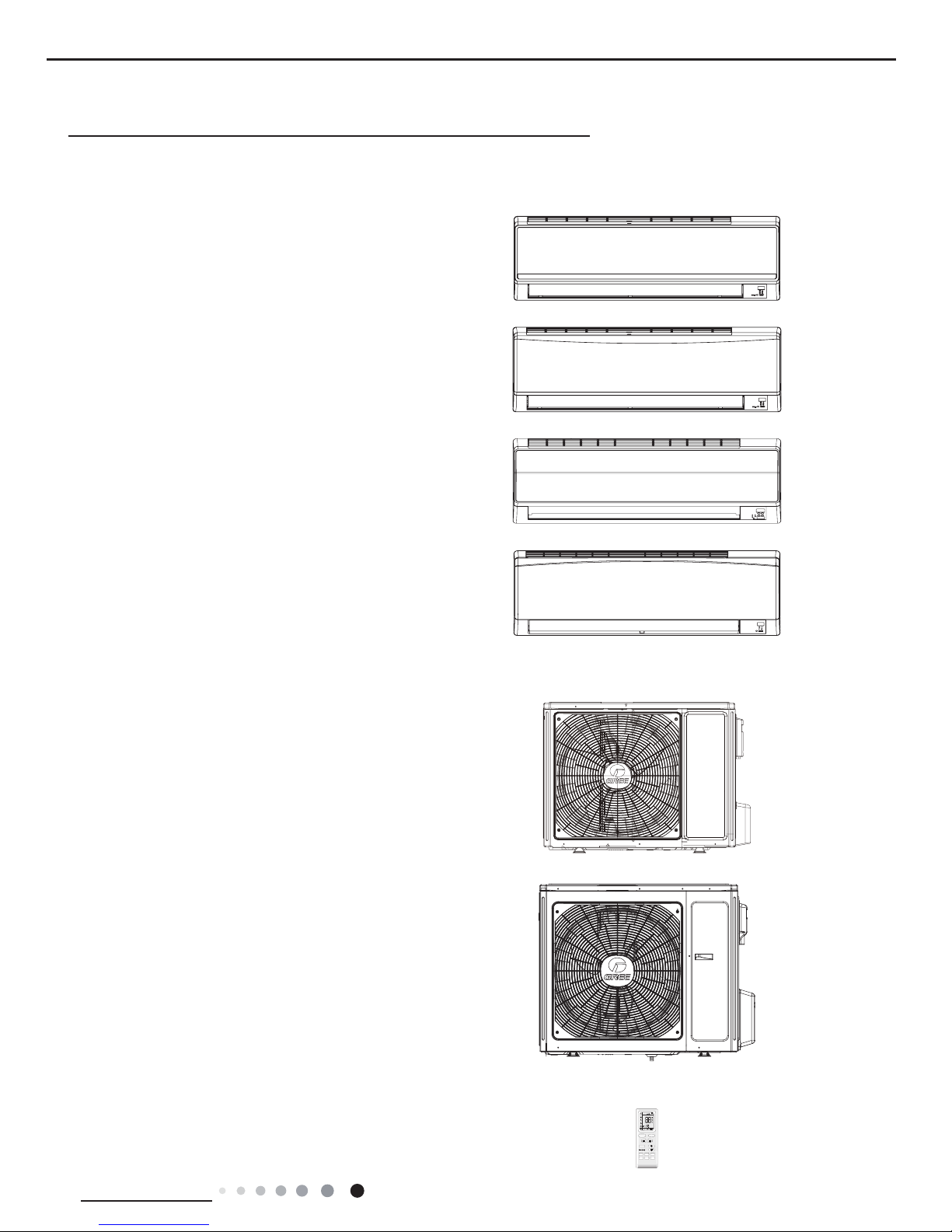
1. Summary
Part
Ⅰ
: Technical Information
Indoor Unit
Outdoor Unit
GWH18KG-K3DNA6G/O
GWH24KG-K3DNA6G/O
GWH18KG-K3DNA6G/I
GWH24KG-K3DNA6G/I
GWH18KG-K3DNA5G/I
GWH24KG-K3DNA5G/I
GWH18KG-K3DNB2G/I
GWH24KG-K3DNB2G/I
GWH18KG-K3DNA9G/I
GWH24KG-K3DNA9G/I
Remote Controller
YB1F2(XFAN)
FAN
AUTO
OPER
HEALTH
AIR
FILTER
TURBO
ON/OFF
X-FAN
HOUR
HUMIDITY
ON/OFF
MODE
FAN
X-FAN
TURBO
TEMP
TIMER
SLEEP
LIGHT
ON/OFF

2
Technical Information
Service Manual
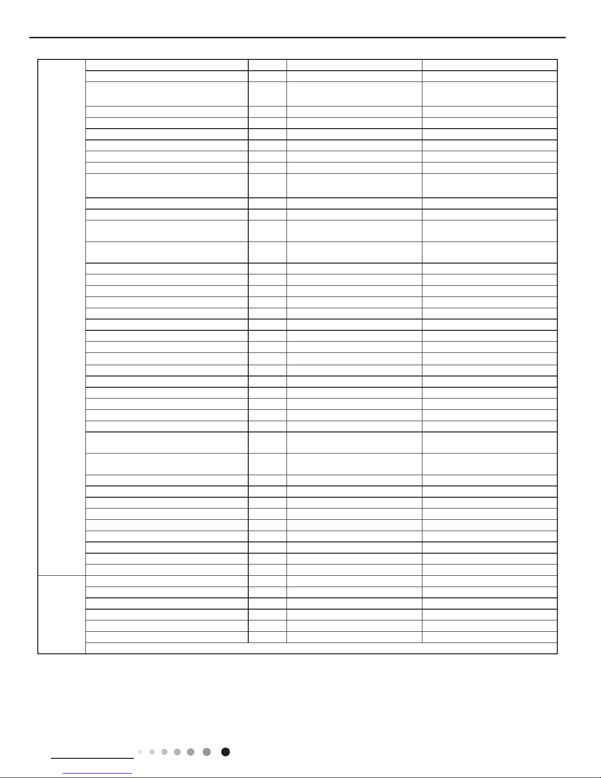
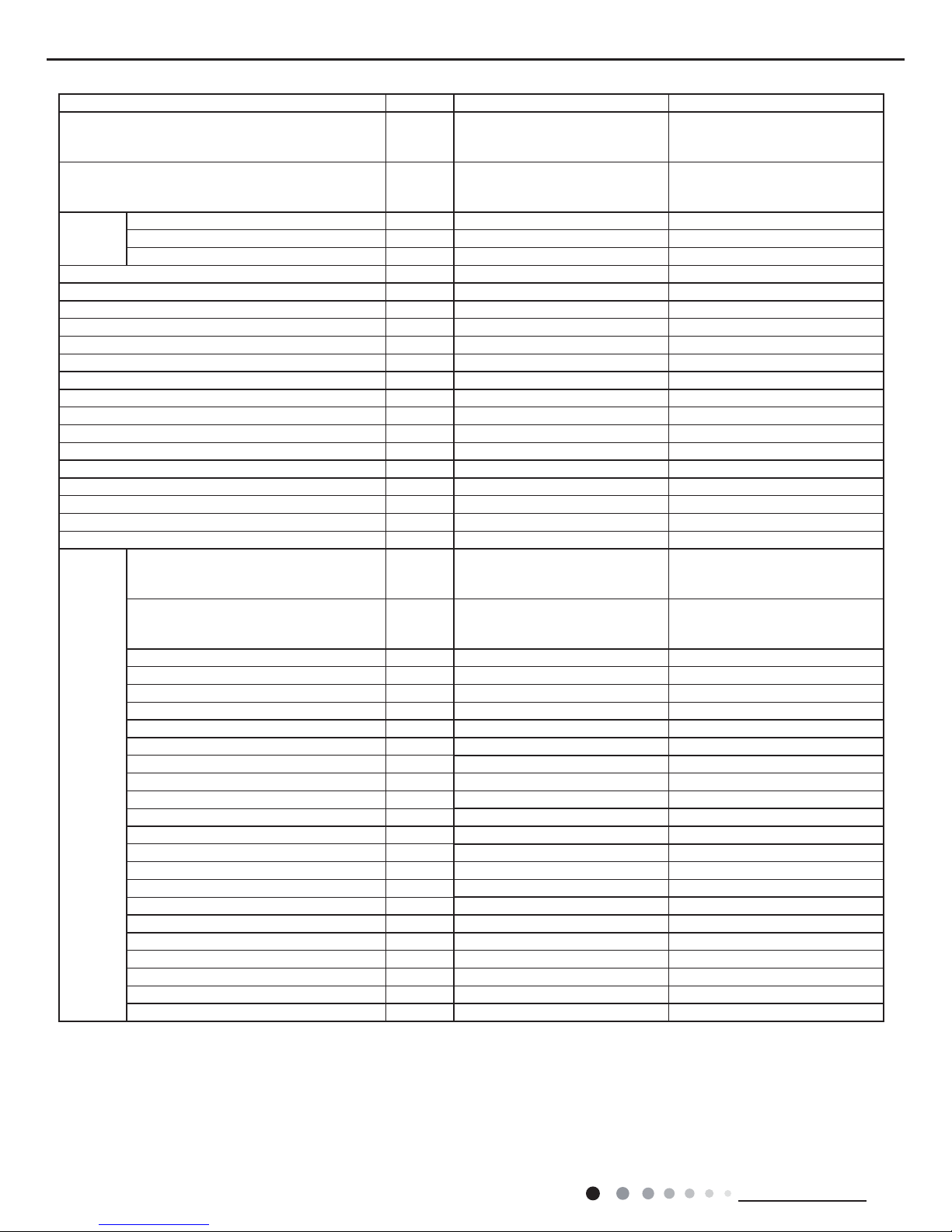
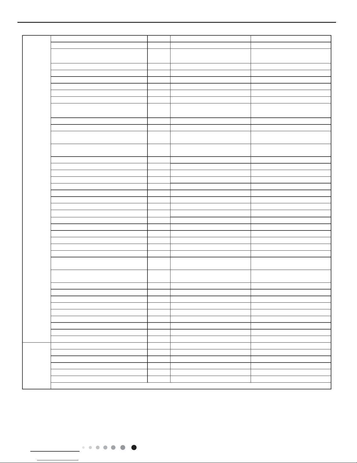
2. Specications
2.1 Specication Sheet
Parameter Unit Value Value
Model
1.GWH18KG-K3DNA6G
2.GWH18KG-K3DNA9G
1.GWH18KG-K3DNA5G
2.GWH18KG-K3DNA6G
3.GWH18KG-K3DNB2G
Product Code
1.CB146036000
2.CB146037300
1.CB146037401
2.CB146036001
3.CB409002501
Power
Supply
Rated Voltage V~ 220-240 220-240
Rated Frequency Hz 50 50
Phases 1 1
Power Supply Mode Outdoor Outdoor
Cooling Capacity(Min~Max) W 5275(1200~6200) 5275(1200~6200)
Heating Capacity(Min~Max) W 5570(1100~6000) 5570(1100~6000)
Cooling Power Input(Min~Max) W 1675(380~2450) 1675(380~2450)
Heating Power Input(Min~Max) W 1750(350~2600) 1750(350~2600)
Cooling Current Input A 7.43 7.43
Heating Current Input A 7.80 7.80
Rated Input W 2650 2650
Rated Current A 11.80 11.80
Air Flow Volume(SH/H/M//L/SL) m
3
/h 800/680/560/460/- 800/680/560/460/Dehumidifying Volume L/h 1.8 1.8
EER W/W 3.15 3.15
COP W/W 3.18 3.18
SEER W/W 5.60 5.60
HSPF W/W / /
Application Area m
2
23-34 23-34
Indoor
Unit
Indoor Unit Model
1.GWH18KG-K3DNA6G/I
2.GWH18KG-K3DNA9G/I
1.GWH18KG-K3DNA5G/I
2.GWH18KG-K3DNA6G/I
3.GWH18KG-K3DNB2G/I
Indoor Unit Product Code
1.CB146N36000
2.CB146N37300
1.CB146N37400
2.CB146N36000
3.CB409N02500
Fan Type Cross-ow Cross-ow
Fan Diameter Length(DXL) mm Ф98X650 Ф98X650
Cooling Speed(SH/H/M//L/SL) r/min 1350/1100/950/800/- 1350/1100/950/800/Heating Speed(SH/H/M//L/SL) r/min 1400/1200/1050/900/- 1400/1200/1050/900/Fan Motor Power Output W 20 20
Fan Motor RLA A 0.31 0.31
Fan Motor Capacitor μF 1.5 1.5
Evaporator Form Aluminum Fin-copper Tube Aluminum Fin-copper Tube
Evaporator Pipe Diameter mm Ф7 Ф7
Evaporator Row-n Gap mm 2-1.4 2-1.4
Evaporator Coil Length (LXDXW) mm 657X25.4X304.8 657X25.4X304.8
Swing Motor Model MP28VB MP28VB
Swing Motor Power Output W 2 2
Fuse Current A 3.15 3.15
Sound Pressure Level(SH/H/M//L/SL) dB (A) 49/44/40/35/- 49/44/40/35/Sound Power Level(SH/H/M//L/SL) dB (A) 60/55/51/46/- 60/55/51/46/Dimension (WXHXD) mm 867X305X215 867X305X215
Dimension of Carton Box (LXWXH) mm 945X380X295 945X380X295
Dimension of Package(LXWXH) mm 948X383X310 948X383X310
Net Weight kg 12 12
Gross Weight kg 15 15
3
Technical Information
Service Manual
Outdoor
Unit
Outdoor Unit Model GWH18KG-K3DNA6G/O GWH18KG-K3DNA6G/O
Outdoor Unit Product Code CB146W36000 CB146W36001
Compressor Manufacturer
ZHUHAI LANDA COMPRESSOR
CO.,LTD
ZHUHAI LANDA COMPRESSOR
CO.,LTD
Compressor Model QXA-B141zF030A QXA-B141zF030A
Compressor Oil 68EP 68EP
Compressor Type Rotary Rotary
Compressor LRA. A 25 25
Compressor RLA A 7.2 7.2
Compressor Power Input W 1440 1440
Compressor Overload Protector
1NT11L-6233 or KSD115
o
C or
HPC115/95U1
1NT11L-6233 or KSD115oC or
HPC115/95U1
Throttling Method Capillary Capillary
Set Temperature Range ºC 16~30 16~30
Cooling Operation Ambient Temperature
Range
ºC -15~43 -15~43
Heating Operation Ambient Temperature
Range
ºC -15~24 -20~24
Condenser Form Aluminum Fin-copper Tube Aluminum Fin-copper Tube
Condenser Pipe Diameter mm Ф7 Ф7
Condenser Rows-n Gap mm 2-1.4 2-1.4
Condenser Coil Length (LXDXW) mm 851X38.1X660 851X38.1X660
Fan Motor Speed rpm 750 750
Fan Motor Power Output W 60 60
Fan Motor RLA A / /
Fan Motor Capacitor μF / /
Outdoor Unit Air Flow Volume m
3
/h 3200 3200
Fan Type Axial-ow Axial-ow
Fan Diameter mm Ф520 Ф520
Defrosting Method Automatic Defrosting Automatic Defrosting
Climate Type T1 T1
Isolation I I
Moisture Protection IP24 IP24
Permissible Excessive Operating Pressure
for the Discharge Side
MPa 4.3 4.3
Permissible Excessive Operating Pressure
for the Suction Side
MPa 2.5 2.5
Sound Pressure Level (H/M/L) dB (A) 55/-/- 55/-/Sound Power Level (H/M/L) dB (A) 65-/- 65-/Dimension(WXHXD) mm 963X700X396 963X700X396
Dimension of Carton Box (LXWXH) mm 1026X455X735 1026X455X735
Dimension of Package(LXWXH) mm 1029X458X750 1029X458X750
Net Weight kg 46 46
Gross Weight kg 50.5 50.5
Refrigerant R410A R410A
Refrigerant Charge kg 1.3 1.3
Connection
Pipe
Connection Pipe Length m 5 5
Connection Pipe Gas Additional Charge g/m 20 20
Outer Diameter Liquid Pipe mm Ф6 Ф6
Outer Diameter Gas Pipe mm Ф12 Ф12
Max Distance Height m 10 10
Max Distance Length m 25 25
Note: The connection pipe applies metric diameter.
The above data is subject to change without notice. Please refer to the nameplate of the unit.
4
Technical Information
Service Manual
Parameter Unit Value Value
Model
1.GWH24KG-K3DNA6G
2.GWH24KG-K3DNA9G
1.GWH24KG-K3DNA5G
2.GWH24KG-K3DNA6G
3.GWH24KG-K3DNB2G
Product Code
1.CB146035900
2.CB146037200
1.CB146037701
2.CB146035901
3.CB409002601
Power
Supply
Rated Voltage V~ 220-240 220-240
Rated Frequency Hz 50 50
Phases 1 1
Power Supply Mode Outdoor Outdoor
Cooling Capacity(Min~Max) W 6450(2530~6550) 6450(2530~6550)
Heating Capacity(Min~Max) W 7000(2530~7600) 7000(2530~7600)
Cooling Power Input(Min~Max) W 2180(600~2650) 2180(600~2650)
Heating Power Input(Min~Max) W 2220(600~2800) 2220(600~2800)
Cooling Current Input A 9.7 9.7
Heating Current Input A 10.5 10.5
Rated Input W 2800 2800
Rated Current A 12.5 12.5
Air Flow Volume(SH/H/M//L/SL) m
3
/h 1000/800/700/550/- 1000/800/700/550/Dehumidifying Volume L/h 2.1 2.1
EER W/W 2.96 2.96
COP W/W 3.15 3.15
SEER W/W 5.60 5.60
HSPF W/W / /
Application Area m
2
23-34 23-34
Indoor
Unit
Indoor Unit Model
1.GWH24KG-K3DNA6G/I
2.GWH24KG-K3DNA9G/I
1.GWH24KG-K3DNA5G/I
2.GWH24KG-K3DNA6G/I
3.GWH24KG-K3DNB2G/I
Indoor Unit Product Code
1.CB146N35900
2.CB146N37200
1.CB146N37700
2.CB146N35900
3.CB409N02600
Fan Type Cross-ow Cross-ow
Fan Diameter Length(DXL) mm Φ98X765 Φ98X765
Cooling Speed(SH/H/M//L/SL) r/min 1350/1150/1000/850/- 1350/1150/1000/850/Heating Speed(SH/H/M//L/SL) r/min 1400/1200/1000/900/- 1400/1200/1000/900/Fan Motor Power Output W 35 35
Fan Motor RLA A 0.31 0.31
Fan Motor Capacitor μF 2.5 2.5
Evaporator Form Aluminum Fin-copper Tube Aluminum Fin-copper Tube
Evaporator Pipe Diameter mm Φ7 Φ7
Evaporator Row-n Gap mm 2-1.5 2-1.5
Evaporator Coil Length (LXDXW) mm 765X25.4X342.9 765X25.4X342.9
Swing Motor Model MP35XX MP35XX
Swing Motor Power Output W 2.5 2.5
Fuse Current A 3.15 3.15
Sound Pressure Level(SH/H/M//L/SL) dB (A) 51/47/42/39/- 51/47/42/39/Sound Power Level(SH/H/M//L/SL) dB (A) 61/57/52/49/- 61/57/52/49/Dimension (WXHXD) mm 1007X315X219 1007X315X219
Dimension of Carton Box (LXWXH) mm 1073X395X313 1073X395X313
Dimension of Package(LXWXH) mm 1076X398X328 1076X398X328
Net Weight kg 14 14
Gross Weight kg 17 17
5
Technical Information
Service Manual
Outdoor
Unit
Outdoor Unit Model GWH24KG-K3DNA6G/O GWH24KG-K3DNA6G/O
Outdoor Unit Product Code CB146W35900 CB146W35901
Compressor Manufacturer
ZHUHAI LANDA COMPRESSOR
CO.,LTD
ZHUHAI LANDA COMPRESSOR
CO.,LTD
Compressor Model QXA-B141zF030A QXA-B141zF030A
Compressor Oil 68EP 68EP
Compressor Type Rotary Rotary
Compressor LRA. A 25 25
Compressor RLA A 7.2 7.2
Compressor Power Input W 1440 1440
Compressor Overload Protector
1NT11L-6233 or KSD115
o
C or
HPC115/95U1
1NT11L-6233 or KSD115oC or
HPC115/95U1
Throttling Method Capillary Capillary
Set Temperature Range ºC 16~30 16~30
Cooling Operation Ambient Temperature
Range
ºC -15~43 -15~43
Heating Operation Ambient Temperature
Range
ºC -15~24 -20~24
Condenser Form Aluminum Fin-copper Tube Aluminum Fin-copper Tube
Condenser Pipe Diameter mm Φ7 Φ7
Condenser Rows-n Gap mm 2-1.4 2-1.4
Condenser Coil Length (LXDXW) mm 984X38.1X748 984X38.1X748
Fan Motor Speed rpm 800 800
Fan Motor Power Output W 90 90
Fan Motor RLA A / /
Fan Motor Capacitor μF / /
Outdoor Unit Air Flow Volume m
3
/h 4000 4000
Fan Type Axial-ow Axial-ow
Fan Diameter mm Φ552 Φ552
Defrosting Method Automatic Defrosting Automatic Defrosting
Climate Type T1 T1
Isolation I I
Moisture Protection IP24 IP24
Permissible Excessive Operating Pressure
for the Discharge Side
MPa 4.3 4.3
Permissible Excessive Operating Pressure
for the Suction Side
MPa 2.5 2.5
Sound Pressure Level (H/M/L) dB (A) 58/-/- 58/-/Sound Power Level (H/M/L) dB (A) 68/-/- 68/-/Dimension(WXHXD) mm 1000X790X427 1000X790X427
Dimension of Carton Box (LXWXH) mm 1080X485X840 1080X485X840
Dimension of Package(LXWXH) mm 1083X488X855 1083X488X855
Net Weight kg 55.5 55.5
Gross Weight kg 60.5 60.5
Refrigerant R410A R410A
Refrigerant Charge kg 1.80 1.80
Connection
Pipe
Connection Pipe Length m 5 5
Connection Pipe Gas Additional Charge g/m 50 50
Outer Diameter Liquid Pipe mm Φ6 Φ6
Outer Diameter Gas Pipe mm Φ16 Φ16
Max Distance Height m 10 10
Max Distance Length m 25 25
Note: The connection pipe applies metric diameter.
The above data is subject to change without notice. Please refer to the nameplate of the unit.
6
Technical Information
Service Manual
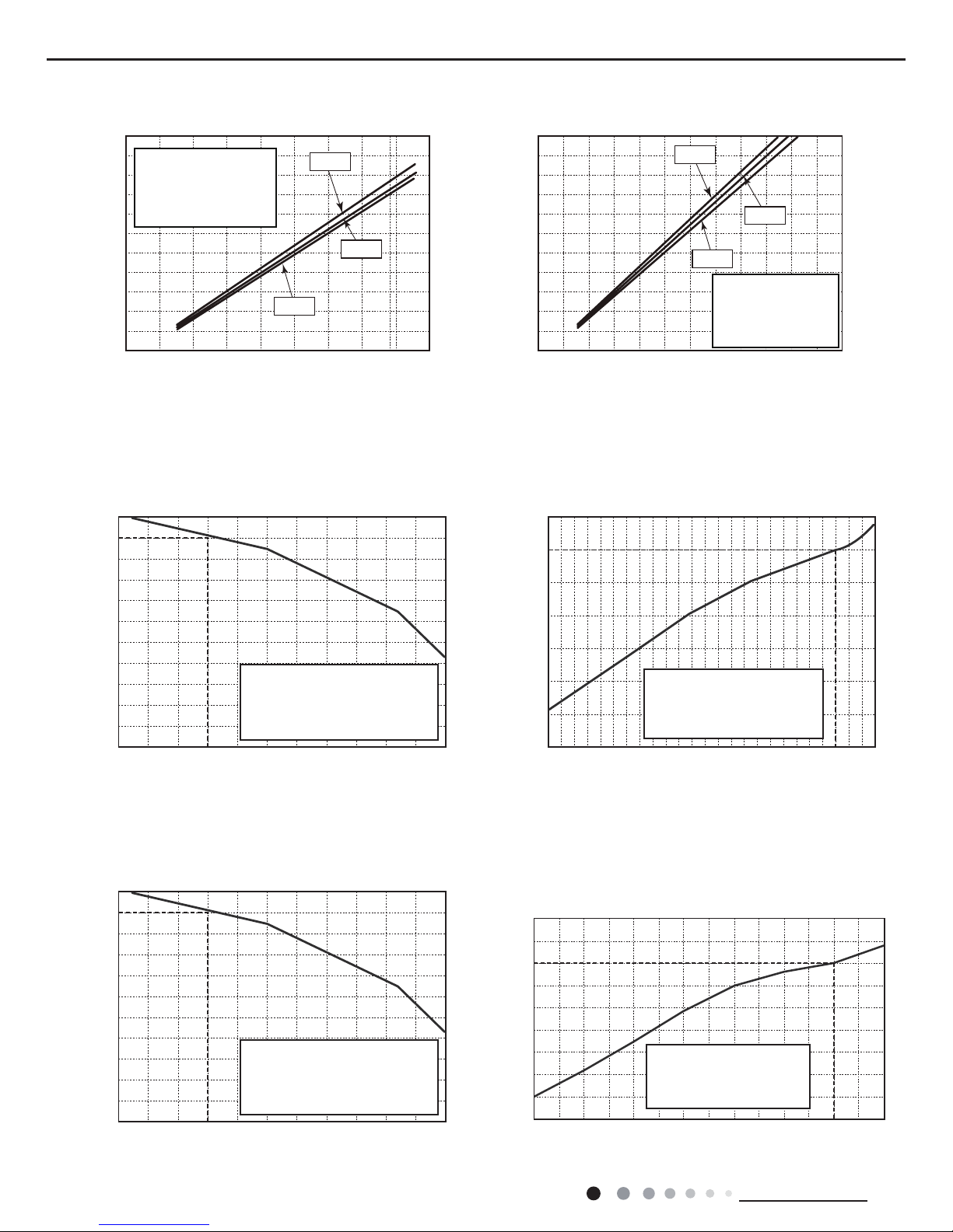
2.2 Operation Characteristic Curve
2.3 Capacity Variation Ratio According to Temperature
0 10 20 30 40 50 60 70 90 0 10 20 30 40 50 60 70 80 90 100 120 110
80
11
10
9
8
7
6
5
4
3
2
1
0
Compressor speed (rps)
) A ( t n e r r u C
11
10
9
8
7
6
5
4
3
2
1
0
Compressor speed (rps)
) A ( t n e r r u C
220V
230V
240V
220V
230V
240V
0 10 20 30 40 50 60 70 90 0 10 20 30 40 50 60 70 80 90 100 120110
80
11
10
9
8
7
6
5
4
3
2
1
0
Compressor speed (rps)
)A(tnerruC
11
10
9
8
7
6
5
4
3
2
1
0
Compressor speed (rps)
)A(tnerruC
220V
230V
240V
220V
230V
240V
Conditions
Indoor: DB27°C/WB19°C
Outdoor: DB35°C/WB24°C
Indoor air flow: High
Pipe length: 5m
Conditions
Indoor: DB27°C/WB19°C
Outdoor: DB35°C/WB24°C
Indoor air flow: High
Pipe length: 5m
Conditions
Indoor: DB20°C/WB15°C
Outdoor: DB7°C/WB6°C
Indoor air flow: High
Pipe length: 5m
Conditions
Indoor: DB20°C/WB15°C
Outdoor: DB7°C/WB6°C
Indoor air flow: High
Pipe length: 5m
Cooling Heating
Cooling Heating
32 33 34 35 36 37 38 39 43 –15 –10 –5
40 41 42
100
105
95
90
85
80
75
70
65
60
55
50
110
100
90
80
70
60
50
40
0 5 7 10
Conditions
Indoor:DB27°C/WB19°C
Indoor air flow:Super High
Pipe length: 5m
Conditions
Indoor:DB20°C/WB15°C
Indoor air flow:Super High
Pipe length: 5m
Outdoor temp.(°C) Outdoor temp.(°C)
Capacity ratio (%)
Capacity ratio (%)
Cooling Heating
Cooling Heating
32 33 34 35 36 37 38 39 43
–15 –10 –5
40 41 42
100
105
95
90
85
80
75
70
65
60
55
50
110
100
90
80
70
60
50
40
0 5 7 10
Conditions
Indoor:DB27°C/WB19°C
Indoor air flow:Super High
Pipe length: 5m
Conditions
Indoor:DB20°C/WB15°C
Indoor air flow:Super High
Pipe length: 5m
Outdoor temp.(°C)
Outdoor temp.(°C)
Capacity ratio (%)
Capacity ratio (%)
30
40
50
60
70
80
90
100
110
120
10750-5-10-15-20
Outdoor temp.(oC)
Capacity ratio(%)
Conditions
Indoor:DB20°C/WB15°C
Indoor air flow:Super High
Pipe length: 5m
Cooling Heating
Heating operation ambient temperature range is -15°C~24°C
Heating operation ambient temperature range is -20°C~24°C
7
Technical Information
Service Manual
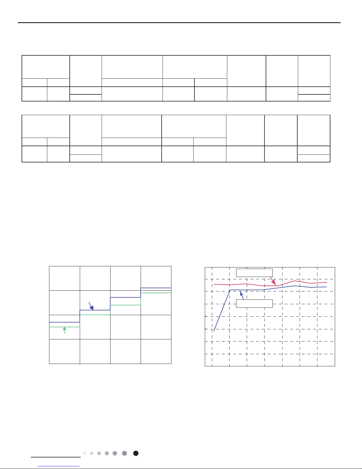
2.4 Cooling and Heating Data Sheet in Rated Frequency
Rated cooling
condition(°C)
(DB/WB)
Model
Pressure of gas pipe
connecting indoor and
outdoor unit
Inlet and outlet pipe
temperature of heat
exchanger
Fan speed of
indoor unit
Fan speed of
outdoor unit
Compressor
frequency
(Hz)
Indoor Outdoor P (MPa) T1 (°C) T2 (°C)
27/19 35/24
18K
0.9 to 1.1 12 to 14 75 to 37 Super High High
73
24K 80
Rated heating
condition(°C)
(DB/WB)
Model
Pressure of gas pipe
connecting indoor and
outdoor unit
Inlet and outlet pipe
temperature of heat
exchanger
Fan speed of
indoor unit
Fan speed of
outdoor unit
Compressor
frequency
(Hz)
Indoor Outdoor P (MPa) T1 (°C) T2 (°C)
20/15 7/6
18K
2.2 to 2.4 70 to 35 2 to 4 Super High High
75
24K 78
Instruction:
T1: Inlet and outlet pipe temperature of evaporator
T2: Inlet and outlet pipe temperature of condenser
P: Pressure at the side of big valve
Connection pipe length: 5 m.
Cooling:
Heating:
2.5 Noise Curve
Indoor side noise when blowing Outdoor side noise when blowing
Indoor fan motor rotating speed
Compressor frequency(Hz)
Noise/dB(A)
50
60
30
40
20
Low
Middle
High
Super High
24K
18K
40
42
44
46
48
50
52
54
56
20 4030 50 60 70 80 90
Noise dB(A)
18&24K Cooling
18&24K Heating
8
Technical Information
Service Manual
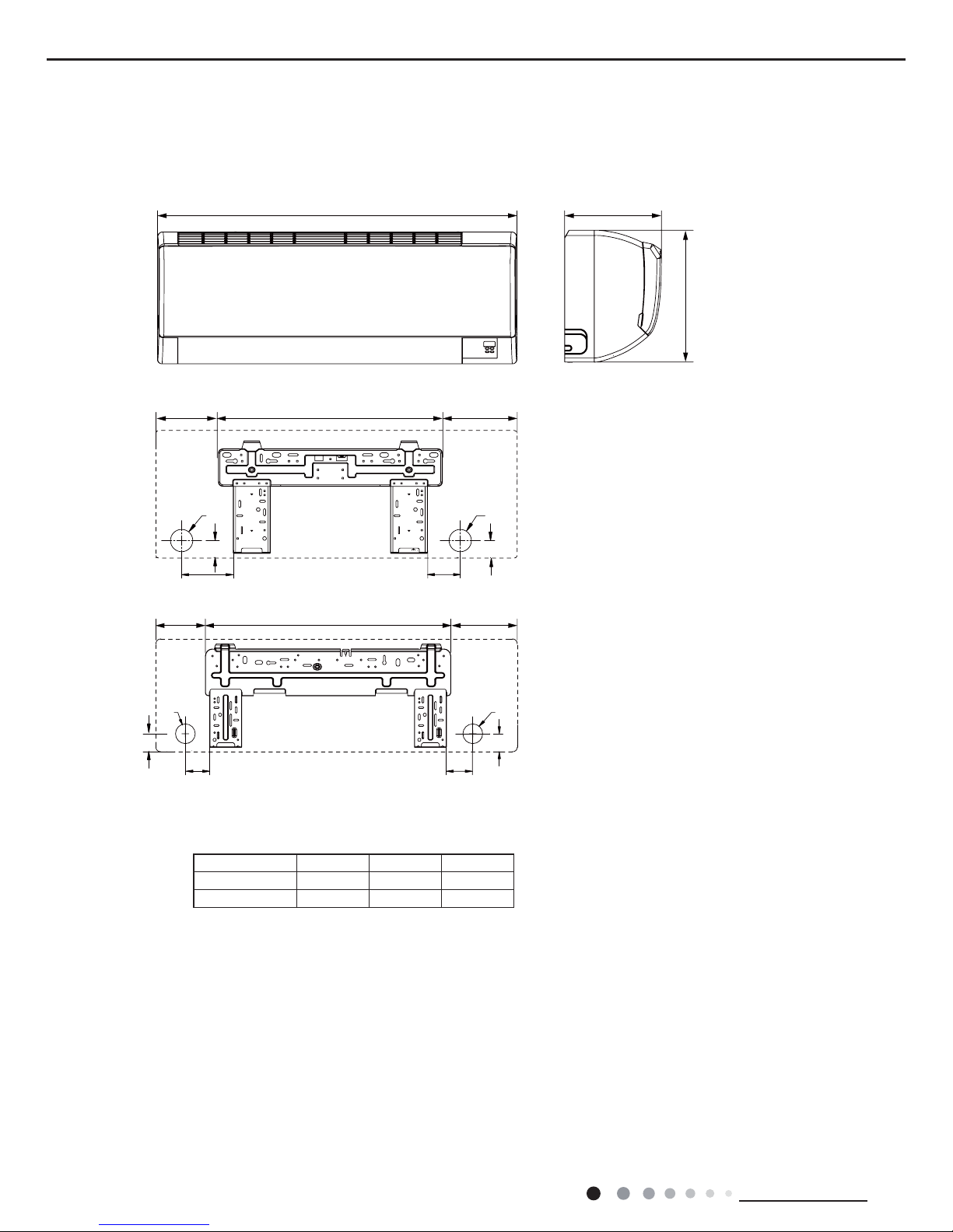
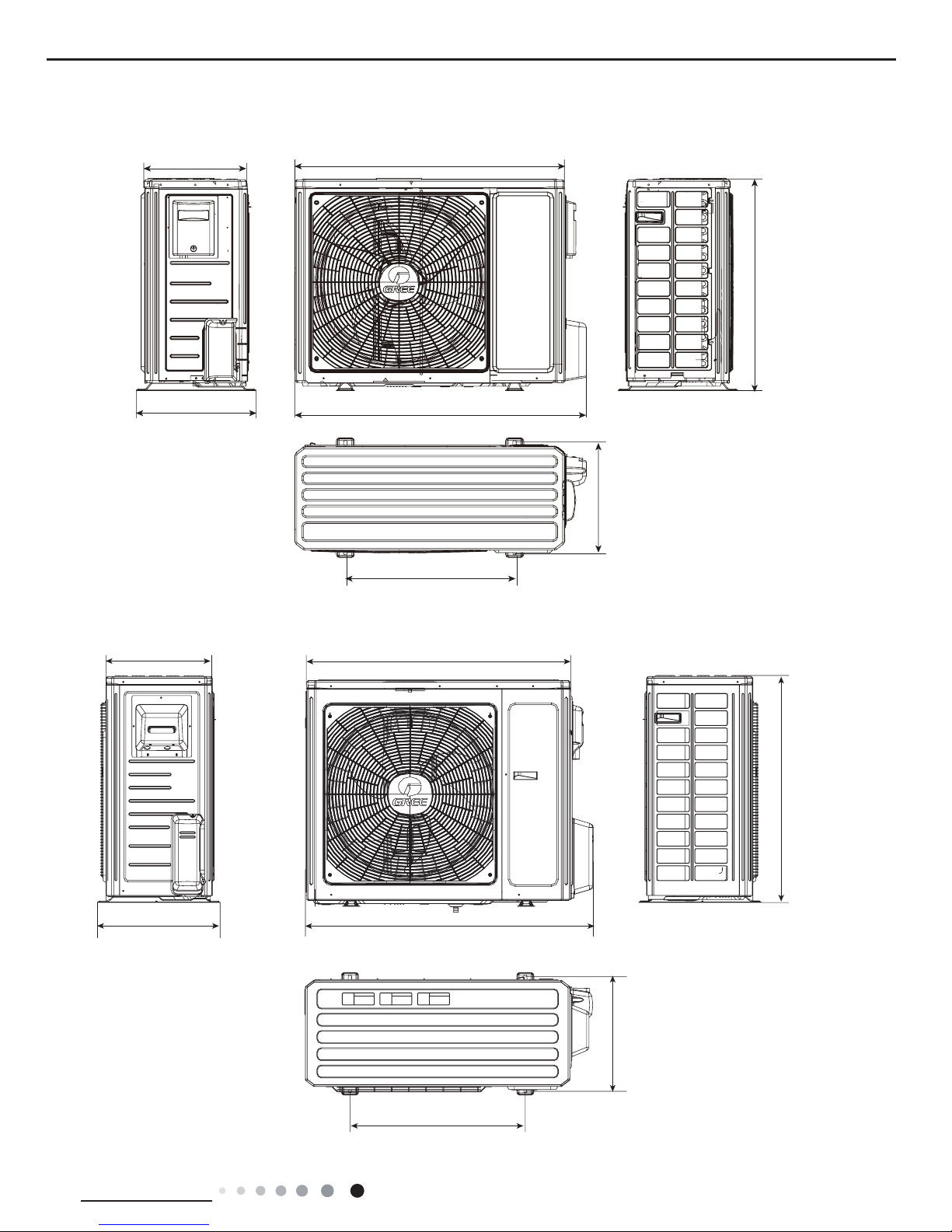
3. Outline Dimension Diagram
3.1 Indoor Unit
Φ70
Φ70
70
90
4545
40
Φ55
Φ55
Φ55
Φ55
40
41.3
41.3
71
161
54
54.5
120.5 548.5
W
D
H
103
149 542 176
130 685 193
W
D
H
unit:mm
24K Unit
18K Unit
Models W H D
18K 867 305 215
24K 1008 319 221
9
Technical Information
Service Manual
3.2 Outdoor Unit
Unit:mm
24K Unit
18K Unit
963
892
700
396
341
368
560
427
1000
920
610
370
790
395
10
Technical Information
Service Manual
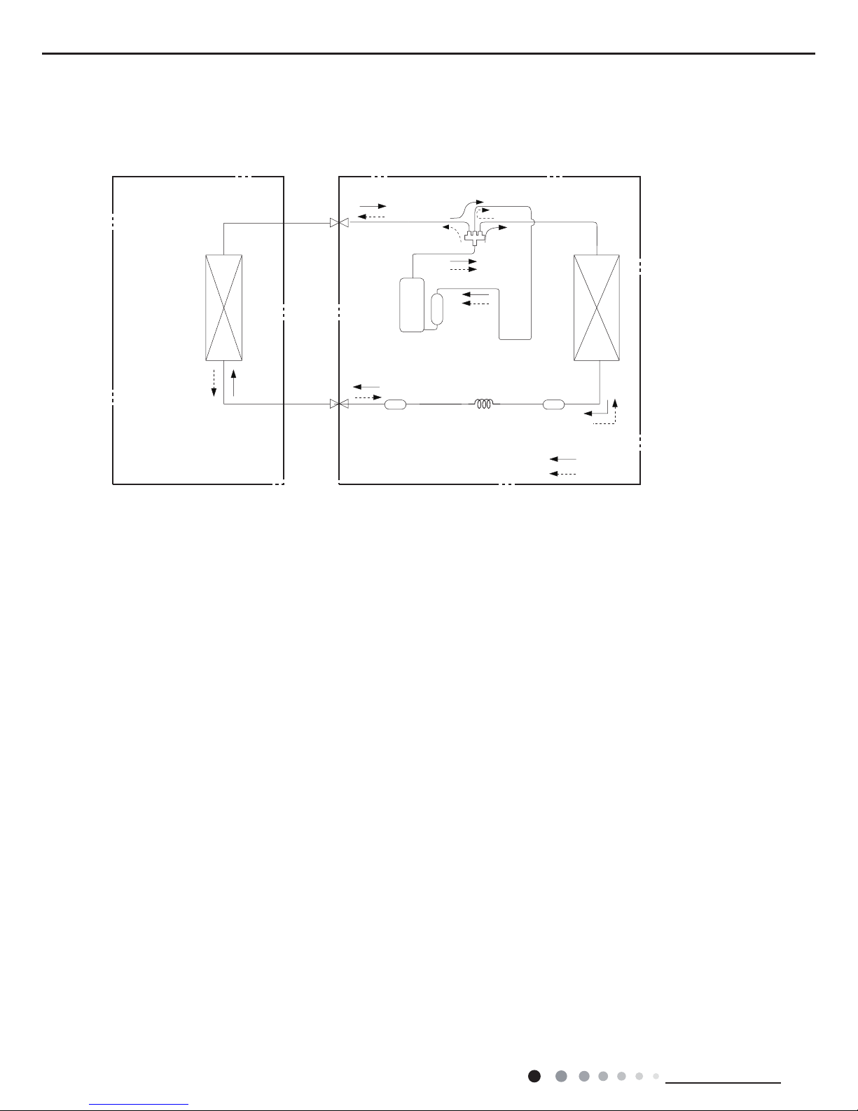
4. Refrigerant System Diagram
Connection pipe specication:
Liquid pipe:1/4" (6mm)
Gas pipe:1/2" (12mm)(18K)
Gas pipe:5/8" (16mm)(24K)
Indoor unit
Outdoor unit
COOLING
HEATING
4-Way valve
Discharge
Suction
Heat
exchanger
(evaporator)
Heat
exchanger
(condenser)
Valve
Valve
Liquid pipe
side
Gas pipe
side
Strainer Electric
expand
valve
Strainer
Capillary
Compressor
Accumlator
11
Technical Information
Service Manual
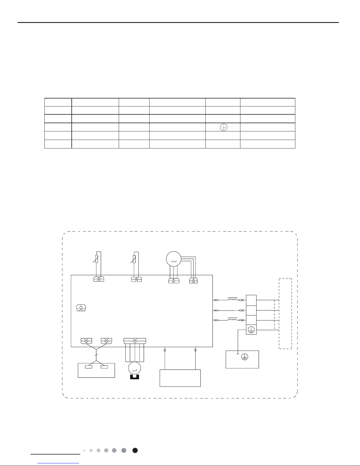
5. Electrical Part
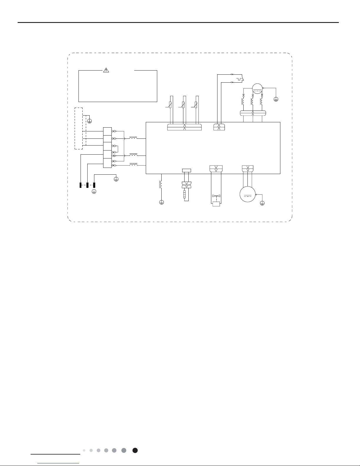
5.1 Wiring Diagram
● Indoor Unit
● Instruction
Symbol Symbol Color Symbol Symbol Color Symbol Name
WH White GN Green CAP Jumper cap
YE Yellow BN Brown COMP Compressor
RD Red BU Blue Grounding wire
YEGN Yellow/Green BK Black / /
VT Violet OG Orange / /
Note: Jumper cap is used to determine fan speed and the swing angle of horizontal lover for this model.
SENSORSENSOR
AC-L
BK
PE
ROOMTUBE
M2
SWING-UD1
ROOM TEMP.
RT2
AP2
BN
PG
YEGN
M1
BU
FAN MOTOR
OUTDOOR UNIT
2
3
XT
N(1)
TUBE TEMP.
RT1
SWING
MOTOR
COM-OUT
N
PGF
CAP
JUMP
DISP2DISP1
AP1
RECEIVER AND
DISPLAY BOARD
EVAPORATOR
TERMINAL
BLOCK
L
L
BU
BK
BN
YEGN
PRINTED CIRCUIT BOARD
HEALTH-L
BU RD
HEALTH-N
GENERATOR
COLD PLASMA
θ
θ
GWH18KG-K3DNA5G/I GWH18KG-K3DNA6G/I GWH18KG-K3DNB2G/I GWH24KG-K3DNA5G/I
GWH24KG-K3DNA6G/I GWH24KG-K3DNB2G/I
12
Technical Information
Service Manual
● Outdoor Unit
GWH18KG-K3DNA6G/O(CB146W36000) GWH24KG-K3DNA6G/O(CB146W35900)
AP1
TEMP.SENSOR
EXHAUST
TEMP.SENSOR
OUTROOM
OUTTUBE
TEMP.SENSOR
BK
WH
BU
YE
X1
COMP
SAT
WH WH
OVC_COMP
RD
RT3RT2RT1
PE
PE
RD
BU YE
U(BU)V(YE)W(RD)
YEGN
T_SENSOR
OVERLOAD PROTECTOR
L3
MAGNETIC
RING
L3
L3
AC_L
N1
COM_INNER
PE
YEGN
PE
N
L
YEGN
BU
PE
N
L
N(1)
2
3
BN
BK
BU
XT1
INDOOR UNIT
L1
RING
BK
BN
BU
BN
BU
YEGN
BLOCK
TERMINAL
PE
MAGNETIC
PE
M1
4-WAY
4YV
VALVE
VT VT
OFAN4WAY
FAN MOTOR
YEGN
PE
L1
PRINTED CIRCUIT BOARD
U V W
L1
COMP.
θ
θ
θ
POWER
Please don't touch any terminal
when the voltage of terminal
P(DC+) and N(DC-) at AP1 is
higher than 30V to prevent the
risk of electric shock !
WARNING
BN
20K 15K 50K
L2
GWH18KG-K3DNA9G/I GWH24KG-K3DNA9G/I
35,17('&,5&8,7%2$5'
<(*1
%1
%.
%8
/
/
%/2&.
7(50,1$/
(9$325$725
',63/$<%2$5'
5(&(,9(5$1'
$3
',63 ',63
-803
&$3
3*)
1
&20287
02725
6:,1*
57
78%(7(03
1
;7
287'22581,7
)$102725
%8
0
<(*1
3*
%1
$3
57
52207(03
6:,1*8'
0
78%( 5220
3(
%.
6(1625 6(1625
$&/
©
©
13
Technical Information
Service Manual
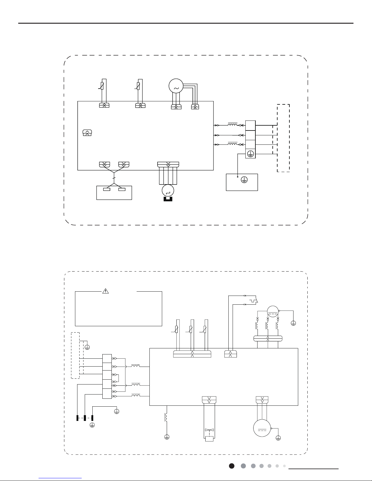
GWH18KG-K3DNA6G/O(CB146W36001) GWH24KG-K3DNA6G/O(CB146W35901)
L2
50K15K20K
BN
WARNING
Please don't touch any terminal
when the voltage of terminal
P(DC+) and N(DC-) at AP1 is
higher than 30V to prevent the
risk of electric shock !
POWER
θ
θ
θ
COMP.
L1
WVU
PRINTED CIRCUIT BOARD
L1
PE
YEGN
FAN MOTOR
4WAY OFAN
VTVT
VALVE
4YV
4-WAY
M1
PE
MAGNETIC
PE
TERMINAL
BLOCK
YEGN
BU
BN
BU
BN
BK
RING
L1
INDOOR UNIT
XT1
BU
BK
BN
3
2
N(1)
L
N
PE
BU
YEGN
L
N
PE
YEGN
PE
COM_INNER
N1
AC_L
L3
L3
RING
MAGNETIC
L3
OVERLOAD PROTECTOR
T_SENSOR
YEGN
W(RD)V(YE)U(BU)
YEBU
RD
PE
PE
RT1 RT2 RT3
RD
OVC_COMP
WHWH
SAT
COMP
X1
YE
BU
WH
BK
TEMP.SENSOR
OUTTUBE
OUTROOM
TEMP.SENSOR
EXHAUST
TEMP.SENSOR
AP1
HEAT_B
EH
RD
BOTTOM
HEATER
BAND
RD
These circuit diagrams are subject to change without notice, please refer to the one supplied with the unit.
14
Technical Information
Service Manual
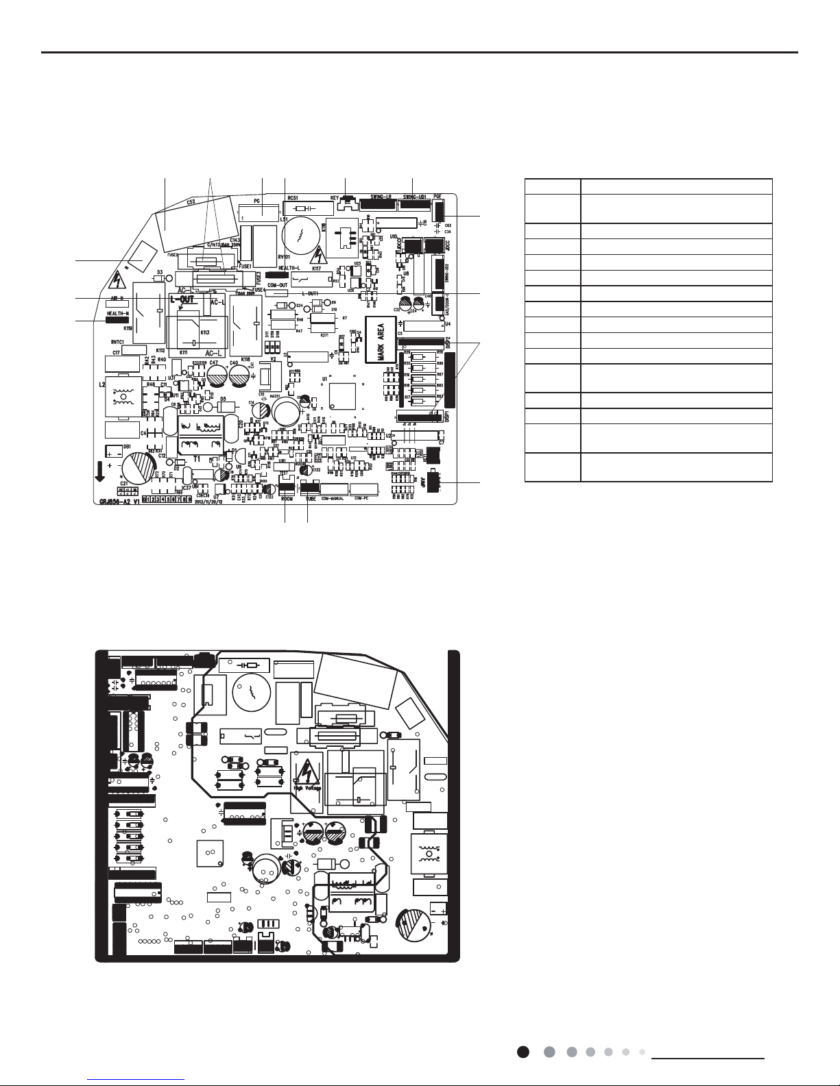
5.2 PCB Printed Diagram
● Top view
Indoor Unit
● Bottom view
No. Name
1
Interface of health function neutral
wire
2 Interface of live wire
3 Interface of neutral wire
4 Capacitor of fan motor
5 Fuse
6 Interface of PG motor
7 Interface of health function live wire
8 Auto button
9 Up & down swing
10 Feedback interface of PG motor
11
Interface of IDU and ODU
communication
12 Display interface
13 Jumper cap
14
Interface of tube temperature
sensor
15
Interface of ambient temperature
sensor
1
2
3
4 5 6 7 8 9
10
11
12
13
1415
15
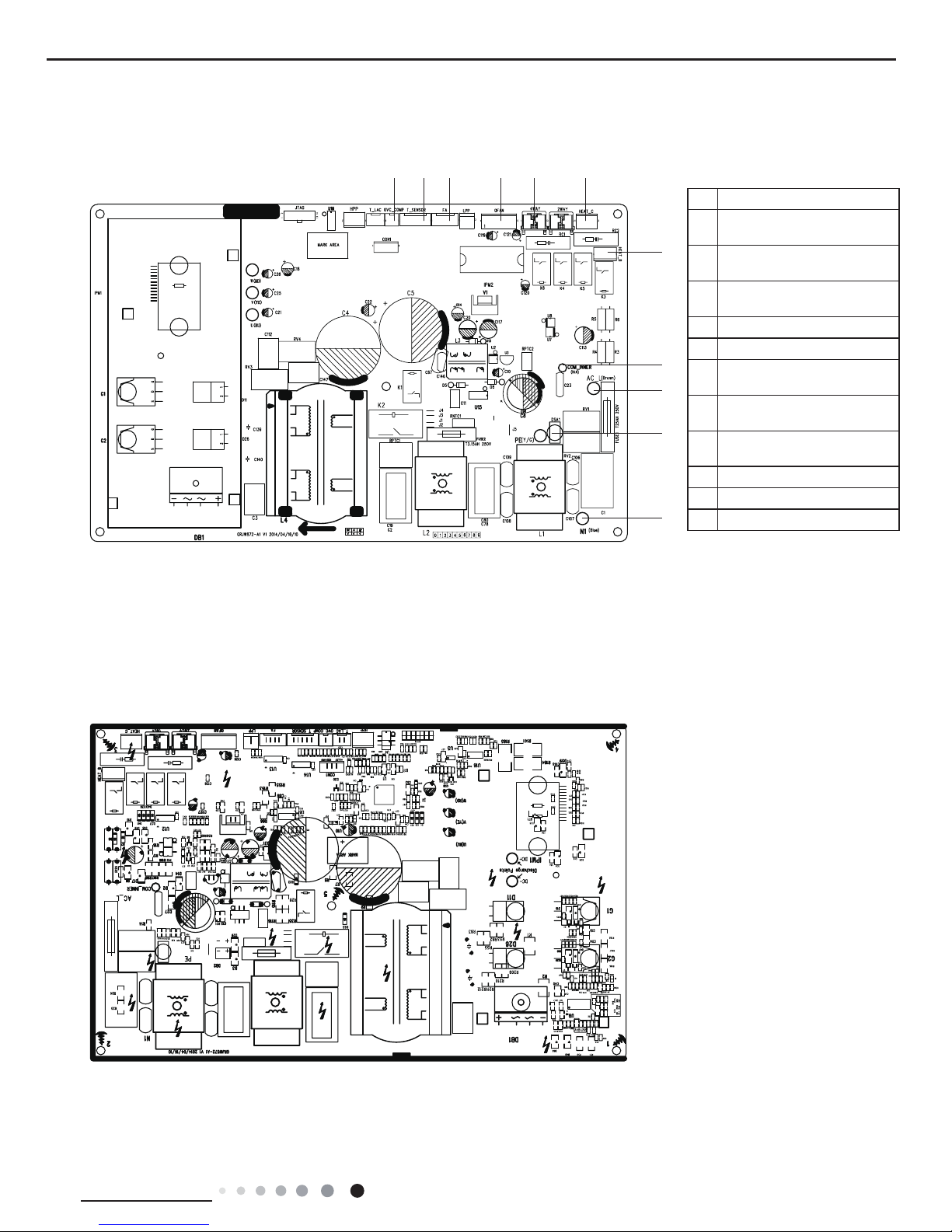
Technical Information
Service Manual
● Top view
Outdoor Unit
● Bottom view
No. Name
1
Terminal of compressor
overload protection
2
Terminal of temperature
sensor
3
Terminal of electronic
expansion valve
4
Terminal of outdoor fan
5
Terminal of 4-way valve
6
Terminal of
compressorelectric heating
7
Terminal of chassis electric
heating
8
Terminal of indoor unit and
outdoor unit communication
9
Power supply live wire
10
Earthing wire
11
Power supply neutral wire
1 2 3 4 5 6
7
8
9
10
11
16
Technical Information
Service Manual
6. Function and Control
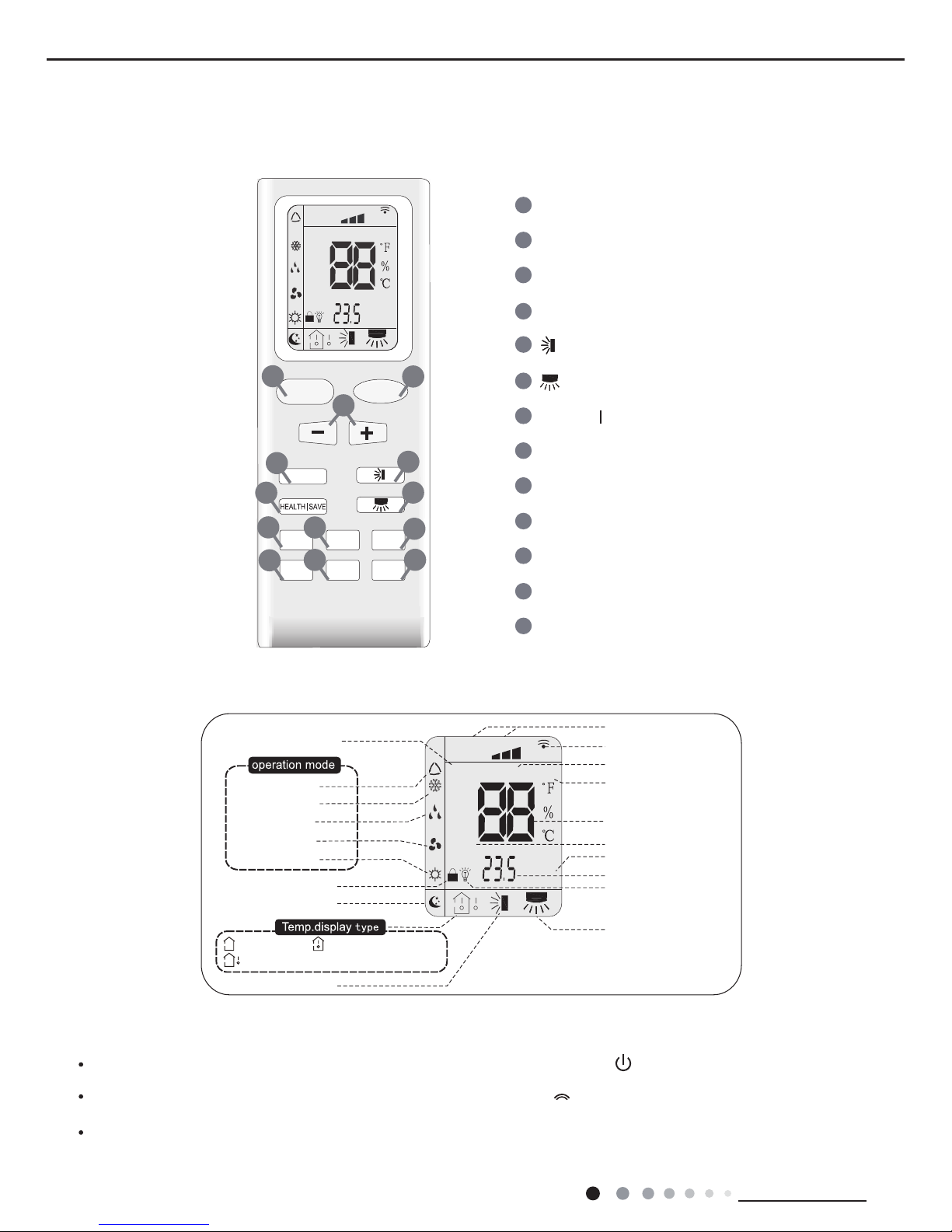
6.1 Remote Controller Introduction
Introduction for buttons on remote controller
Note:
After putting through power, air conditioner will give out a sound and operation indicator "
" is ON (red indicator). You can operate the air
conditioner through the remote controller.
At ON status, after each pressing button on remote controller, the signal icon "
" on remode controller will ash once. Air conditioner will
give out a sound, which indicates the signal has been sent to air conditioner.
At OFF status, display screen on remote controller displays set temperature. At on status, display screen on remote controller displays
the corresponding start up function’s icon.
Buttons on remote controller
Introduction for icons on display screen
ON/OFF Button
2
3
1
5
6
4
9
10
8
12
13
11
MODE Button
+/- Button
X-FAN Button
TEMP Button
TURBO Button
SLEEP Button
LIGHT Button
Button
HEALTH SAVE Button
7
Button
TIMER Button
FAN Button
FAN
AUTO
OPER
HEALTH
AIR
FILTER
TURBO
ON/OFF
X-FAN
HOUR
HUMIDITY
ON/OFF
MODE
FAN
X-FAN
TURBO
TEMP
TIMER
SLEEP
LIGHT
2
10
7
9
12
8
3
11
6
5
13
4
1
Child lock
Left&right swing
Sleep mode
Auto mode
Air mode
Cool mode
Heat mode
Fan mode
Dry mode
Up&down swing
:Indoor ambient temp.:Set temp.
:Outdoor ambient temp.
FAN
OPER
AUTO
HEALTH
AIR
FILTER
TURBO
ON/OFF
X-FAN
HOUR
HUMIDITY
TIMER ON/TIMER OFF
Set time
Light
Send signal
Health mode
X-fan
Set fan speed
Set temperature
Turbo mode
Temp. display type
Operation mode
17
Technical Information
Service Manual
1.ON/OFF button
Press this button can turn on or turn off the air conditioner. After turning on the unit,operation indicator "
" on indoor unit is ON (green
indicator. Color may be differ-ent for different models)and indoor unit gives out a sound.
2.MODE button
Press this button can select your required operation mode.
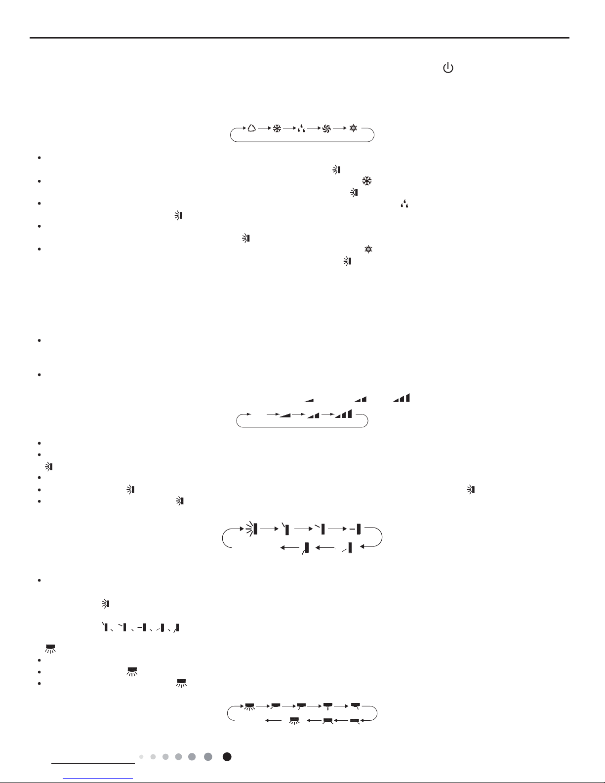
AUTO COOL DRYF AN HEAT
After selecting auto mode, air conditioner will operate automatically according to ambient temperature. Set temperature can’t be adjusted
and also can’t be displayed. Press "FAN" button can adjust fan speed. Press "
" button can adjust swing angle.
After selecting cool mode, air conditioner operates under cool mode. Cool indicator "
" on indoor unit is ON. You can press "+" or "-"
button to adjust set temperature. Press "FAN" button can adjust fan speed. Press "
" button can adjus t swing angle.
After selecting dry mode, air conditioner operates under dry mode at low speed. Dry indicator "
" on indoor unit is ON. Under dry mode,
fan speed can’t be adjusted. Press "
" button to adjust swing angle.
After selecting fan mode, air conditioner operates only under fan mode, All mode indicators on indoor unit is OFF. Operation indicator is
ON. Press "FAN" button can adjust fan speed. Press "
" button to adjust swing angle.
After selecting heat mode, air conditioner operates under heat mode. Heat indicator "
" on indoor unit is ON. You can press "+" or "-"
button to adjust set temperature. Press "FAN" button to adjust fan speed. Press "
" button to adjust swing angle. (Cooling only unit can’t
receive the signal for heating mode.)
Note:
For preventing cold wind, after starting up heating mode, indoor fan will blow fan afterdelaying 1-5min. (Details time is decided by indoor
ambient temperature) Temperature setting range on remote controller: 16
o
C~30oC(61oF~86oF) . Fan speed setting range: auto, low speed,
medium speed and high speed.
3."+" or "-" button
After each pressing of "+" or "-" button, it can increase or decrease set temperature 1
o
C(1oF~2oF) . Hold "+" or "-" button, 2s later, set
temperature on remote controller will change quickly. After reaching to your required time, loosen the button. Temperature indicator on
indoor unit will also change accordingly. (Temperature can’t be adjusted under auto mode)
Under TIMER ON, TIMER OFF or Clock setting, you can press "+"or "-" button to adjust time. (Refer to TIMER button for details)
4.FAN button
Pressing this button can set fan speed circularly as: auto (AUTO), low(
), medium( ), high( ).
Note:
Under AUTO Speed,IDU fan motor will adjust the fan speed (high, medium or low speed) according to ambient temperature.
Fan speed under dry mode is low speed.
5.
button
Press this button to start or stop up & down swing function.The remote controller defaults to simple swing condition.
Press "+" button and "
" button at the same time at unit OFF to switch between simple swing and static swing; " " blinks for 2 seconds.
In static swing condition, pressing "
" button, the swing angle of up & down louver changes as below:
If the unit is turned off during swing operation,the louver will stop at present position.
Note:
When selecting "
" with remote controller, it’s auto swing. Horizontal louver of air conditioner will swing up&down automatically at the
maximum angle.
When selecting "
" with remote controller, it is the xed position swing. Horizontal louver of air conditioner will stop at
that position as shown by the icon to swing.
6.
button
Press this button to start or stop left & right swing function. The remote controller defaults to simple swing condition.
Press "+" button and "
" button at the same time at unit OFF to switch between simple swing and static swing; blinks for 2 seconds.
In static swing condition, pressing "
" button, the swing angle of left & right louver changes as below:
AUTO
no display
(horizontal louvers
stops at current
position)
no display
(horizontal
louvers stops
at current
position)
(swing angle is
displayed
dynamically)
18
Technical Information
Service Manual
If the unit is turned off during swing operation,the louver will stop at present position.
When selecting "
" with remote controller, it is the xed position swing. Horizontal louver of air conditioner will stop at
that position as shown by the icon to swing.
When selecting "(
swing angle is displayed dynamically
)" it’s the circulating swing. Horizontal louver of air conditioner will swing circularly according to
the angle as shown by the icon.
Note:
There is no this function for the units. If press this key, the main unit will click, but it also runs under original status.
7.HEALTH/SAVE button
After pressing HEALTH button, remote controller will switch circularly as below: "HEALTH"→"AIR"→"AIR HEALTH"→"no display"
When selecting "HEALTH" by remote controller, HEALTH function will be started up.
When selecting "AIR" by remote controller, AIR function will be started up.
When selecting "AIT HEALTH", AIR and HEALTH function will be started up.
When there’s no display on remote controller, AIR and HEALTH function will be turned off.
AIR function is applicable for some models.
SAVE function:
Under cool mode, press SAVE button and the unit will operate under SAVE mode. Dual-8nixie tube on remote controller displays "SE".
Air conditioner will operate at auto speed. Set temperature can’t be adjusted. Press SAVE button again to exit SAVE mode. Air conditioner
turn back to original set speed and set temperature.
This function is applicable to partial of models.
8.X-FAN button
After pressing this button under cooling or dry mode, remote controller displays the character of "X-FAN" and X-FAN function is started up.
Press this button again to cancel X-FAN function. The character of "X-FAN" will disappear.
Note:
After starting up X-FAN function, when turning off the unit, indoor fan will continue to operate for a while at low speed to dry the residual
water inside the indoor unit.
When the unit operates under X-FAN mode, press "X-FAN" button can turn off X-FAN function. Indoor fan stops operation immediately.
9.TEMP button
Press this button can see indoor set temperature, indoor ambient temperature or outdoor ambient temperature on indoor unit’s display.
Temperature is set circularly by remote controller as below:
When selecting "
" by remote controller or no display, temperature indicator on indoor unit displays set temperature.
When selecting "
" by remote controller, temperature indicator on indoor unit displays indoor ambient temperature.
When selecting "
" by remote controller, temperature indicator on indoor unit displays outdoor ambient temperature.
Note:
Outdoor ambient temperature display may can’t be selected for some models. When indoor unit receives "
" signal, it displays indoor
set temperature.
Only for the model whose indoor unit has dual-8 display.
10.TIMER button
At ON status, press this button once can set TIMER OFF. The character of HOUR and OFF will ash.Press "+" or "-" button within 5s
can adjust the time of TEMER ON. After each pressing of "+" or "-" button, time will increase or decrease half an hour. When holding "+"
or "-" button, 2s later, the time will change quickly until to reach to your required time. After that, press "TIMER" button to conrm it. The
character of HOUR and OFF won't ash again.
Cancel TIMER OFF: Press "TIMER" button again under TIMER OFF status.
At OFF status, press this button once can set TIMER ON. Please refer to TIMER off for detailed operation.
Cancel TIMER ON: Press "TIMER" button again under TIMER ON status.
Note:
Time setting range: 0.5-24 hours.
Time interval between two operations can’t exceed 5s. Otherwise, remote controller will exit the setting status automatically.
11.TURBO button
When pressing this button under cooling or heating mode, air conditioner will enter into quick cooling or quick heating mode. The
character of "TURBO" is displayed on remote controller. Press this button again to exit turbo function and the character of "TURBO" will be
disappeared on remote controller.
12.SLEEP button
Press this button under cooling, heating mode can start up sleep function."
" icon will be displayed on remote controller. Press this button
again to cancel sleep function. "
" icon on remote controller will be displayed.
13.LIGHT button
Press this button can turn off the light for indoor unit’s display. "
" icon on remote controller will disappear. Press this button again to turn
on the light for indoor unit’s display. "
" icon on remote controller will be displayed.
no display
19
Technical Information
Service Manual
Function introduction for combination buttons
Child lock function
Press "+" and "-" buttons simultaneously can turn on or turn off child lock function. When child lock function is started up, "
" icon will be
displayed on remote controller. If operate remote controller "
" icon will ash three times, while remote controller won’t send signal.
Switchover function for temperature display
After turning off the unit by remote controller, press "-" button and "MODE" button simultaneously to switch between
o
C and °F.
Operation guide
1. After putting through the power, press "
" button on remote controller to turn on the air conditioner.
2. Press "
" button to select your required mode: AUTO, COOL, DRY, FAN, HEAT.
3. Press "+" or "-" button to set your required temperature. (Temperature can’t be adjusted under auto mode).
4. Press "
" button to set your required fan speed: auto, low, medium and high speed.
5. Press "
" button to select fan blowing angle.
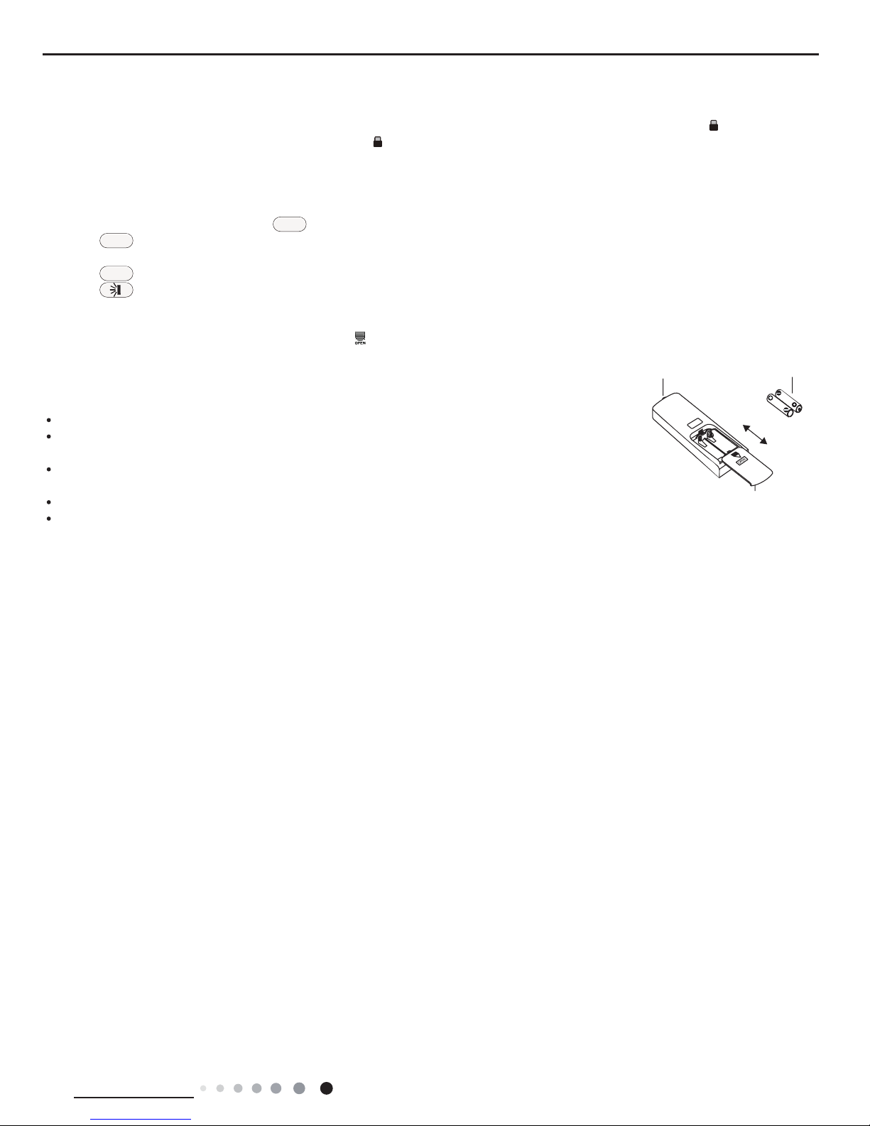
Replacement of batteries in remote controller
1. Press the back side of remote controller marked with "
", as shown in the g, and then push out the cover of battery box along the arrow
direction.
2. Replace two 7# (AAA 1.5V) dry batteries, and make sure the position of "+" polar and "-" polar are correct.
3. Reinstall the cover of battery box.
NOTICE
During operation, point the remote control signal sender at the receiving window on indoor unit.
The distance between signal sender and receiving window should be no more than 8m, and there should
be no obstacles between them.
Signal may be interfered easily in the room where there is uorescent lamp or wireless telephone; remote
controller should be close to indoor unit during operation.
Replace new batteries of the same model when replacement is required.
When you don’t use remote controller for a long time, please take out the batteries.
If the display on remote controller is fuzzy or there’s no display, please replace batteries.
ON/OFF
MODE
FAN
signal sender battery
Cover of battery box
remove
reinstall

20
Technical Information
Service Manual
6.2 Brief Description of Modes and Functions
Indoor Part
Temperature Parameter
◆
Room setting temperature (Tpreset)
◆
Room ambient temperature (Tamb.) (temperature sensor :15K, partial pressure resistance:15K)
◆
Surface temperature of copper pipe for indoor heat exchanger (Tindoor tube) (temperature sensor: 20K, partial pressure resistance:
20K)
1. Basic Functions of System
(1) Cooling Mode
①
In this mode, indoor fan and swing will operate according to the setting status. The temperature setting range is 16~30°C.
②
When the unit stop operation due to malfunction of outdoor unit or protection, indoor unit will keep original operating status.
Malfunction code will be displayed.
③
When 0≤(Tpreset-Tamb.), if the indoor unit is operating at high fan speed, the speed of fan will change to medium fan speed; if the
indoor unit is operating at medium or
low fan speed, the speed of fan will keep the same; (This condition can only be carried out after the compressor is started up);
Theres no change for super-high fan speed; when (Tamb.-Tpreset)≥1°C, the fan speed will resume setting fan speed;
(2) Dry Mode
①
In this mode, fan will operate at low fan speed and swing will operate at setting status. The temperature setting range is 16~30°C.
2. When the unit stop operation due to malfunction of outdoor unit or protection, indoor unit will keep original operating status.
Malfunction code will be displayed.
(3) Fan Mode
①
In this mode, indoor fan will operate at high, medium, low or auto fan speed. Compressor, indoor fan and the four-way valve will all
stop operation.
②
In this mode, the temperature setting range is 16~30°C.
(4) Heating Mode
①
In this mode, the temperature setting range is 16~30°C.
②
Working condition and process of heating: when the unit is turned on in heating mode, indoor unit enters into anti-cold air condition;
when the unit is tuned off, the unit will enter into the condition of blowing residual heat.
③
Protection function: in heating mode, when the compressor is stopped due to malfunction, indoor fan will operate at the condition of
blowing residual heat.
④
Defrosting control: after receiving the defrosting signal from outdoor unit, heating indicator on indoor unit OFF 0.5s and ON 10s.
⑤
Anti-cold function
⑥
Blowing residual heat function;
a) During heating operation, when the stopping condition for the compressor is reached, the compressor and the outdoor fan motor
stop operation. The upper& down horizontal louver will rotate to the horizontal position L. The indoor fan will be stopped after operating
for 60s at setting speed.
b) Due to the blockage of PG motor, horizontal louver will keep the stop position when the unit is turned off. (In other modes) When the
unit is stopped due to other malfunctions,up&down horizontal louver will rotate to horizontal position L. The indoor fan will be stopped
after operating for 60s at setting speed.
c) If the unit is turned off when the compressor is operating in heating mode or auto heating mode, up&down horizontal louver will rotate
to horizontal position L. The indoor fan will be stopped after operating for 60s at setting speed.
(5) Auto Mode
①
When Tamb.≥26°C, the unit will operate in cooling mode. The implied setting temperature is 25°C.
②
Heat pump type: when Tamb.≤22°C, the unit will operate in heating mode. The implied setting temperature is 20°C.
③
Cooling only unit: when Tamb.≤25°C, the unit will operate in auto mode. The implied setting temperature is 25°C.
④
When 23°C≤Tindoor amb. ≤25°C, the unit will operate in auto fan mode if the unit is turned on and enters into the auto mode for the
rst time. If the unit is switched to auto mode from other mode, it will keep the previous operation mode (if the unit is switched to auto
mode from dry mode, the unit will operate at auto fan mode).
2. Display Status of Indoor Indicator(NOTE:Nixie tube is not available for A8 panel.)
(1) Status of Indoor Display Board
①
After energization, all the icons will be displayed and then only the power indicator is bright. When the unit is turned on by remote
controller, the operation indicator will be bright. Meanwhile, the current setting operation mode will be displayed.
②
During defrosting, heating indicator on indoor unit OFF 0.5s and ON 10s.
③
“Dual-8” displays setting temperature.
●Display of operation icon and mode icon
After energization, all the icons will be displayed for once. In standby status, the operation indicator will be in red. If turn on the unit by
remote controller, the operating indication icon will be bright. Meanwhile, the current setting operation mode will be displayed (mode
indicator: cooling indicator, heating indicator, dry indicator). If turn off the light button, all displays will be turned off.
●Temperature display control mode for split type unit
①
When user set the remote controller as the setting temperature display status, the current setting temperature will be displayed on

21
Technical Information
Service Manual
remote controller.
②
Only when the remote control signal is switched to indoor ambient temperature display status from other display status, controller will
display the indoor ambient temperature
for 3s and then turn back to display the setting temperature.
③
When user hasnt set the temperature displaying status, it will be displayed according to the setting temperature.
(2)Malfunction Display of Indoor Unit
When multiple malfunctions occurred simultaneously, malfunction protection codes will be displayed in cycle.
3.Other Control Target
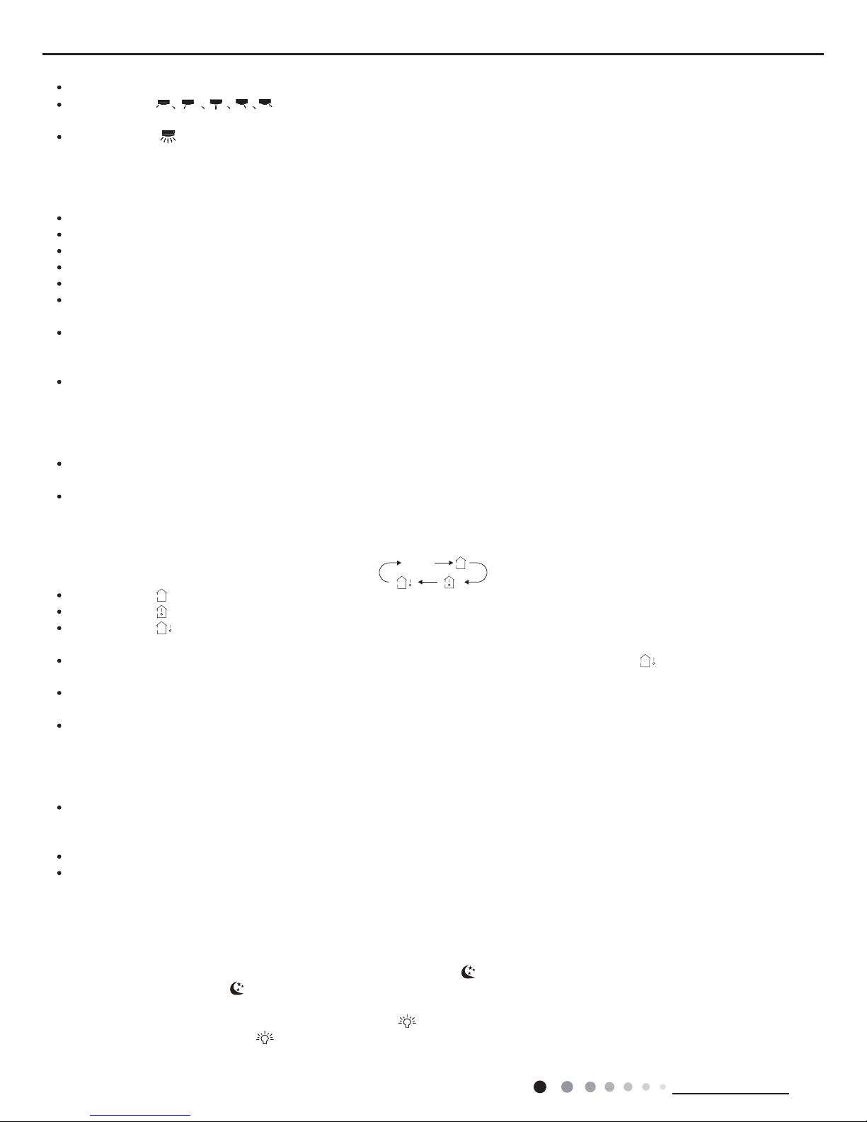
(1) Up&down swing function
After energization, up & down swing motor will rstly let the horizontal louver anticlockwise rotate to
position 0 to close air outlet.
If swing function has not been set after startup of the unit, up & down horizontal louver will clockwise
turn to position D in HEAT mode, or clockwise turn to level position L in other modes.
If setting swing function while starting up the unit, the horizontal louver will swing between L and D.
There are 7 kinds of swing status of horizontal louver: Positions L, A, B, C and D, swing between L and D
and stop at any position between L and D.
Upon turning off the unit, the horizontal louver will close at position 0. Swing function is available only when swing
function set and indoor fan is operating.
Note: If the position is set between L and B, A and C or B and D by remote controller, the horizontal louver will swing between L and D.
L----A----B----C----D
(2) Buzzer
Upon energization and operation, the buzzer will give out sound.
(3) Auto Button
After pressing this button, the unit will operate in auto mode. Indoor fan will operate at auto fan speed and swing motor will operate.
Press this button again to turn off the unit. The complete unit is energized when pressing the button and the complete unit will enter into
fast testing status. After energization, if its detected that the auto button is pressed down and the complete unit is at fast testing status,
the fast testing status will be exited.
(4) Sleep Function
This mode is only valid in cooling and heating mode. The unit will select the appropriate sleeping curve to operate according to the
different setting temperature.
During cooling mode:
①
When the initial temperature is set as 16~23°C, after starting up the sleep function, the temperature will increase by1°C every one
hour.After the temperature has increased by 3°C, the unit will keep this temperature. When the unit has operated for 7 hours, the
temperature will decrease by 1°C and then the unit will operate at this temperature all the time;
②
When the initial temperature is set as 24~27°C, after starting up the sleep function, the temperature will increase by1°C every one
hour.After the temperature has increased by 2°C, the unit will keep this temperature. When the unit has operated for 7 hours, the
temperature will decrease by 1°C and then the unit will operate at this temperature all the time;
③
When the initial temperature is set as 28~29°C, after starting up the sleep function, the temperature will increase by1°C every one
hour.After the temperature has increased by 1°C, the unit will keep this temperature. When the unit has operated for 7 hours, the
temperature will decrease by 1°C and then the unit will operate at this temperature all the time;
④
When the initial temperature is set as 30°C, the unit will operate at this temperature. After the unit has operate for 7hours, the
temperature will decrease by 1°C and then the unit will operate at this temperature all the time.
During Heating Mode:
①
When the initial temperature is set at 16°C, the unit will operate at this temperature all the time;
②
When the initial temperature is set as 17~20°C, after starting up the sleep function, the temperature will decrease by1°C every one
hour.After the temperature is decreased by 1°C, the unit will operate at this temperature;
③
When the initial temperature is set as 21~27°C, after starting up the sleep function, the temperature will decrease by1°C every one
hour.After the temperature is decreased by 2°C, the unit will operate at this temperature;
④
When the initial temperature is set as 28~30°C, after starting up the sleep function, the temperature will decrease by1°C every one
hour.
After the temperature is decreased by 3°C, the unit will operate at this temperature;
General timer and clock timer functions are compatible by equipping different functions of remote controller.
(5) Timer Function
General timer and clock timer functions are compatible by equipping different functions of remote controller.
General timer:
Timer ON
If timer ON is set during operation of the unit, the unit will continue to operate. If timer ON is set at unit OFF, upon ON time reaches the
unit will start to operate according to previous setting status.

22
Technical Information
Service Manual
Timer OFF
If timer OFF is set at unit OFF, the system will keep standby status. If timer OFF is set at unit ON, upon OFF time reaches the unit will
stop operation.
(6) Blow Function
Blow function can be set in cooling and dry mode.
(7) Indoor Fan Control
Indoor fan can be set at super-high, high, medium or low. Meanwhile, the fan will operate at super-high, high, medium and low fan
speed respectively and it can also set at auto fan speed.
(8) Memory Function
Memory content includes mode, up & down swing, light, set temperature and set fan speed, general timer (clock timer cant be
memorized), Upon power failure, the unit after power recovery will automatically start operation according to memorized content. The
unit, without timer setting before power failure, will operate according to the last setting after power recovery. The unit, with general
timer setting which has not been ful lled before power failure, will memorize the time setting and re-calculate the time after power
recovery. If there is timer function in the last remote controller command but setting time has reached, the system will act as timer on/off
setting before power failure. After power failure, the system memorizes the operation states before power failure without timer action.
Clock timer can not be memorized.
(9) Locked protection to PG motor
If the indoor fan motors rotational speed after startup keeps slow for a continuous period of time, the unit will stop operation and display
“H6”.
(10)Turbo Function
This function can be set in cooling or heating mode to quickly cool or heat the room(Turbo function is not available in auto, dry and fan
mode). After pressing the turbo button, indoor fan will operate at super-high fan speed.
4. Malfunction Detection for Temperature sensor
(1) Indoor ambient temperature sensor:
Malfunction of temperature sensor will be detected at any time;
(2) Indoor tube temperature sensor
Malfunction of temperature sensor wont be detected during defrosting period. It starts detecting the malfunction of temperature sensor
after defrosting is nished for 5 mins. Malfunction of temperature sensor will be detected at any other time.
(3) Protection of temperature sensor
1. When the temperature sensor is detected short circuit for 5s successively:
The detected temperature by the temperature sensor is too high and the complete unit will stop operation, meanwhile, the protection
and malfunction of temperature sensor will be displayed accordingly.
2. When the temperature sensor is detected open circuit for 5s successively: The unit will stop operation due to protection and the
corresponding malfunction of temperature sensor will be displayed directly.
5. Refrigerant Recovery Function (applicable when changing installation location or in maintenance)
(1) Enter refrigerant recovery function
Within 5min after energizing(unit ON or OFF status is ok),continuously press LIGHT button for 3 times within 3s to enter refrigerant
recycling mode; Fo is displayed and refrigerant recycling function is started. At this moment, the maintenance people closs liquid valve.
After 5min, stick the thimble of maintenance valve with a tool. If there is no refrigerant spraying out, close the gas valve immediately
and then turn off the unit to remove the connection pipe.
(2) Exit refrigerant recovery function
After entering refrigerant recycling mode, when receive any remote control signal or enter refrigerant recycling mode for 25min, the unit
will exit refrigerant recycling mode automatically if the unit is in standby mode before refrigerant recycling, it will be still in standby mode
after nishing refrigerant recycling; if the unit is in ON status before refrigerant recycling, it will still run in original operation mode.
6.Compulsory Defrosting Function
(1) Start up compulsory defrosting function
Under ON status, set heating mode with remote controller and adjust the temperature to 16
o
C. Press “+, -, +, -, +,-” button successively
within 5s and the complete unit will enter into compulsory defrosting status. Meanwhile, heating indicator on indoor unit will ON 10s and
OFF 0.5s successively. (Note: If complete unit has malfunction or stops operation due to protection, compulsory defrosting function can
be started up after malfunction or protection is resumed.
(2) Exit compulsory defrosting mode
After compulsory defrosting is started up, the complete unit will exit defrosting operation according to the actual defrosting result, and
the complete unit will resume normal heating operation.

23
Technical Information
Service Manual
Outdoor Part
1. Input Parameter Compensation and Calibration
①
Check the input parameter compensation function
As the instruction feature of split unit, concerning the comfortable, in heating mode, the indoor ambient temperature of compressor
stopping time is higher than preset temperature.
②
Check effective judgment controls of parameters
Effective judgment function of the outdoor exhaust temperature thermo-bulb
When conditions a and b are satised, the outdoor exhaust temperature thermo-bulb is judged not to be connected into place, the
mainboard of outer units will display failure of the outdoor exhaust temperature thermo-bulb (not connected into place), stop the unit for
repairing, and resume it by remote controls of ON/OFF.
2. Basic Functions
(1) Cooling Mode
①
Conditions and processes of cooling operation:
a) If the compressor is stop, and [T
preset
– (T
indoor ambient
– ΔT
cooling indoor ambient temperature compensation
)] ≤ 0.5°C, start up the unit for cooling, and start
to cooling operation;
b) During operations of cooling, if 0°C ≤ [T
preset
– (T
indoor ambient
–ΔT
cooling indoor ambient temperature compensation
)] < 2°C, the cooling operation will be still
running;
c) During operations of cooling, if 2°C ≤ [T
preset
– (T
indoor ambient
–ΔT
cooling indoor ambient temperature compensation
)], the cooling operation will stop after
reaching to the temperature point.
②
Temperature setting range
a) If T
outdoor ambient
≥ [T
low-temperature cooling
], the temperature can be set at: 16~30°C (Cooling at room temperature);
b) If T
outdoor ambient
< [T
low-temperature cooling
], the temperature can be set at: 25~30°C (Cooling at low temperature), that is, the minimum setting
temperature for outdoor unit judgment is 25°C.
(2) Dry Mode
①
Conditions and processes of dry operations: Same as the cooling mode;
②
The temperature setting range is: 16~30°C;
(3) Fan Mode
1. The compressor, outdoor fan and four-way valve are switched off;
②
The temperature setting range is: 16~30°C.
(4) Heating Mode
①
Conditions and processes of heating operations: (T
indoor ambient
is the actual detection temperature of indoor environment thermo-bulb,
ΔT
heating indoor ambient temperature compensation
is the indoor ambient temperature compensation during heating operations)
a) If the compressor is stop, and [(T
indoor ambient
–ΔT
heating indoor ambient temperature compensation
) –T
preset
] ≤ 0.5°C, start the machine to enter into heating
operations for heating;
b) During operations of heating, if 0°C ≤ [(T
indoor ambient
–ΔT
heating indoor ambient temperature compensation
) –T
preset
] < 2°C, the heating operation will be still
running;
c) During operations of heating, if 2°C ≤ [(T
indoor ambient
–ΔT
heating indoor ambient temperature compensation
) –T
preset
], the heating operation will stop after
reaching the temperature point.
②
The temperature setting range in this mode is: 16~30°C.
(5) Defrosting Control
①
After the time for defrosting is judged to be satised, if the temperature for defrosting is satised after detections for continuous
3minutes, the defrosting operation will start.
②
Start to defrost: Compressor stops and starts up 55S later;
③
Defrosting nish: Compressor stops and starts up 55S later;
④
Conditions of nishing defrosting
The defrosting operation can exit when any of the conditions below is satised:
a) T
outdoor pipe
≥ 12°C;
b) T
outdoor ambient
<-5°C, and the Toutdoor pipe≥ 6°C last more than 80S;
c) The continuous running time of defrosting reaches to 8min.
(6) Compressor Control

24
Technical Information
Service Manual
①
The frequency of compressor will be controlled with the relationship of ambient temperature and preset temperature and changing
speed of ambient temperature;
②
Start the compressor after starting cooling, heating, dry operations, and the outdoor fan start for 5s;
③
When the unit is off, in safety stops and switching to fan mode, the compressor will stop immediately;
④
In all modes: once the compressor starts up, it will not be allowed to stop until having run for the [T
min. Compressor running time
] (Note:
including cases of shutdown when the temperature point is reached; except the cases requiring stopping the compressor such as fault
protection,remote shutdown, mode switching etc.);
⑤
In all modes: once the compressor stops, it will be allowed be restart after 3-minute delay (Note: The indoor units have a function of
power memory, the machine can be restarted after remote shutdown and powering up again without delay).
(7) Outdoor Fan Control
①
When the unit is off by remote control, in safety stops and stop after reaching to the temperature point.
②
In fan mode: The outdoor fan stops;
③
Start to defrost: Outdoor fan will stop after compressor stops for 50S;
④
Defrosting nish: Outdoor fan will start up when the compressor is stopping.
(8) 4-way valve control
①
The 4-way valve control under the modes of Cooling, dehumidi cation and fan: closing;
②
When the unit is on in heating mode, the 4-way valve is energized;
③
When the unit is on in heating mode and heating mode shift to other modes, the 4-way valve will be de-energized after compressor
stops for 2min;
④
After protection stops, the 4-way valve will be de-energized after 4min;
⑤
Start to defrost: The power of 4-way valve will be de-energized after the compressor stops;
⑥
Defrosting nish: The 4-way valve will be energized after the compressor stops.
(9)Freeze prevention protection
①
Under cooling or drying mode, if it detected that Tindoor tube <0°C for 3 min successively, the unit will stop operation due to freeze
prevention protection. If 6°C<Tindoorr tube, and compressor has stopped for 3min, the complete unit can be allowed to resume
operation;
②
Under cooling or drying mode, if Tindoor tube<6°C, the operation frequency of compressor may decrease or the operation frequency
of compressor may stop increasing,
③
If the unit stops operation due to freeze prevention protection for 6 times successively, the unit cant resume operation automatically
and error code will be displayed successively. Only press ON/OFF button can resume the operation. During operation process, if
compressor operates for more than 10min, times of stop operation due to freeze prevention protection will be cleared.
Malfunction and malfunction times will be cleared immediately when turning off the unit or switch to fan/heating mode.
(10)Overload protection function
①
Overload protection function under cooling or drying mode, if 65°C≤Toutdoor tube, the unit stops operation due to overload protection
under cooling; if Toutdoor tube<55°C, and compressor has stopped for 3mins, the complete unit can then be allowed to resume
operation;
②
under cooling or drying mode, if 55°C≤Toutdoor tube, operation frequency of compressor will decrease or operation frequency of
compressor will stop increasing;
③
Overload protection function under heating mode, if 64°C≤Tindoor tube, the unit will stop operation due to overload protection under
heating, If Tindoor tube<54°C, and compressor has stopped for 3min, the complete unit can then be allowed to resume operation;
④
Under heating mode, if 54°C≤Tindoor tube, operation frequency of compressor will decrease or operation frequency of compressor
will stop increasing;
⑤
If the unit stops operation due to overload protection for 6 times successively, the unit cant resume operation automatically and error
code will be displayed successively. Only press ON/OFF button can resume the operation. During operation process, if compressor
operates for more than 10min, times of stop operation due to overload protection will be cleared. Malfunction and malfunction times will
be cleared immediately when turning off the unit, under fan mode or switching to heating mode.
(11)Discharge temperature protection function of compressor
①
If 115°C≤Tdischarge, the unit stops operation due to discharge protection; if Tdischarge<97°C, and compressor has stopped for
3min,the complete unit can then be allowed to resume operation;
②
If 97°C≤Tdischarge, operation frequency of compressor will decrease or operation frequency of compressor will stop increasing;
③
If the unit stops operation due to discharge temperature protection of compressor for 6 times successively, the unit cant resume

25
Technical Information
Service Manual
operation automatically and error code will be displayed successively. Only press ON/OFF button can resume the operation. During
operation process, if compressor operates for more than 10min, times of stop operation due to discharge protection will be cleared.
Malfunction and malfunction times will be cleared immediately when turning off the unit, or switching to fan mode.
(12)Current protection function
①
If 12A ≤ I AC current, operation frequency of compressor will decrease or operation frequency of compressor will stop increasing;
②
If 17 A ≤ I AC current, the unit stops operation due to overcurrent protection. When compressor has stopped operation for 3min, the
complete unit can then be allowed to resume operation.
③
If the unit stops operation due to overcurrent protection for 6 times successively, the unit cant resume operation automatically.
Only press ON/OFF button can resume the operation. During operation process, if compressor operates for more than 10min, times
of stop operation due to overcurrent protection will be cleared.
(13)Voltage-dropping protection
During operation, if the voltage is decreasing quickly, the unit may stop operation and alarm voltage-dropping malfunction. 3 mins
later, the unit will be restarted up automatically.
(14)Communication malfunction
If it hasnt received the correct signal from indoor unit for 3min successively, the unit will stop operation due to communication
malfunction; If communication malfunction is resumed and compressor has stopped for 3min, the complete unit can then be allowed to
resume operation.
(15)IPM module protection
After compressor is turned on, if it causes overcurrent to IPM modular, or control voltage is too low due to some abnormal causes, IP
will generate modular protection signal. Main chip will detect the modular protection signal as soon as the unit is turned on. Once
modular protection signal is detected, the unit will stop operation immediately due to protection. If modular protection is resumed and
compressor has stopped for 3min, the complete unit can then be allowed to resume operation.
If the unit stops operation due to modular protection for 3 times successively, the unit cant resume operation automatically, except
pressing ON/OFF button. If compressor has operates for more than 10 min successively, the stop operation times due to modular
protection will be cleared.
(16)Modular overheating protection
①
If 80°C≤Tmodular, operation frequency of compressor will decrease or operation frequency of compressor will stop increasing;
②
If 95°C≤Tmodular, the unit will stop operation due to protection; if Tmodular<87°C, and compressor has stopped for 3min, the
complete unit can then be resume operation;
③
If the unit stops operation due to modular overheating protection for 6 times successively, the unit cant resume operation
automatically. Only press ON/OFF button can resume the operation. During operation process, if compressor operates for more
than 10min, times of stop operation due to modular overheating protection will be cleared. Malfunction times will be cleared immediately
when turning off the unit, or switching to fan mode.
(17)Overload protection of compressor
①
If it detected that overload switch of compressor breaks for 3s successively, the system will stop operation due to protection;
②
If it detected overload protection is resumed, and compressor has stopped for 3min, the complete unit can then be allowed to
resume operation;
③
If it detected that the unit stops operation due to overload protection of compressor for 3 times successively, the unit cant resume
operation automatically, except pressing ON/OFF button. After compressor operates for 30min, overload protection times of compressor
will be cleared.
 Loading...