

Gree GWH24ACD-K3NNA1A, GWH24AAD-K3NNA1A/O, GWH24ACD-K3NNA1A/I, YAW1F Service Manual

GREE ELECTRIC APPLIANCES,INC.OF ZHUHAI
Change for Life
Service Manual
Model:
GWH24ACD-K3NNA1A
(Refrigerant R410A)

Service Manual
Table of Contents
Part
Ⅰ
: Technical Information
.......................................................................1
1. Summary
......................................................................................................................1
2. Specications
..........................................................................................................2
2.1 Specication Sheet ...........................................................................................................2
2.2 Capacity Curve in Different Outdoor Temperature ...........................................................4
2.3 Cooling and Heating Data Sheet in Rated Frequency .....................................................4
3. Outline Dimension Diagram
........................................................................5
3.1 Indoor Unit ........................................................................................................................5
3.2 Outdoor Unit .....................................................................................................................6
4. Refrigerant System Diagram
......................................................................7
5. Electrical Part
...........................................................................................................8
5.1 Wiring Diagram .................................................................................................................8
5.2 PCB Printed Diagram .....................................................................................................10
6. Function and Control
...................................................................................... 11
6.1 Remote Controller Introduction .....................................................................................11
6.2 Brief Description of Modes and Functions ......................................................................15
Part
Ⅱ
: Installation and Maintenance
.................................................20
7. Notes for Installation and Maintenance
..........................................20
8. Installation
................................................................................................................23
8.1 Installation Dimension Diagram ......................................................................................23
8.2 Installation Parts-Checking ............................................................................................25
8.3 Selection of Installation Location ....................................................................................25
8.4 Requirements for electric connection .............................................................................25
8.5 Installation of Indoor Unit ................................................................................................25
8.6 Installation of Outdoor unit .............................................................................................28
8.7 Vacuum Pumping and Leak Detection ...........................................................................29
8.8 Check after Installation and Test operation ....................................................................29
9. Maintenance
............................................................................................................30
9.1 Error code .......................................................................................................................30
9.2 Procedure of Troubleshooting ........................................................................................32
9.3 Maintenance method for normal malfunction .................................................................40
Table of Contents

Service Manual
10. Exploded View and Parts List
..............................................................42
10.1 Indoor Unit ....................................................................................................................42
10.2 Outdoor Unit .................................................................................................................45
11. Removal Procedure
.......................................................................................47
11.1 Removal Procedure of Indoor Unit ...............................................................................47
11.2 Removal Procedure of Outdoor Unit ............................................................................52
Appendix:
........................................................................................................................57
Appendix 1: Reference Sheet of Celsius and Fahrenheit ....................................................57
Appendix 2: Conguration of Connection Pipe .....................................................................57
Appendix 3: Pipe Expanding Method ...................................................................................58
Appendix 4: List of Resistance for Temperature Sensor ......................................................59
Table of Contents
1
Technical Information
Service Manual
1. Summary
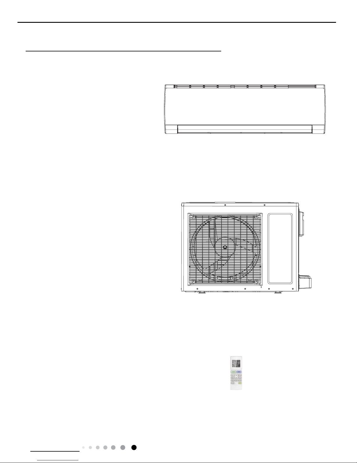
Indoor Unit:
GWH24ACD-K3NNA1A/I
Part
Ⅰ
: Technical Information
Outdoor Unit:
GWH24AAD-K3NNA1A/O
Remote Controller:
YAW1F
2
Technical Information
Service Manual
Model GWH24ACD-K3NNA1A
Product Code CA497000600/CA497000601/CA497000602/CA497000603
Power
Supply
Rated Voltage V~ 220-240
Rated Frequency Hz 50
Phases 1
Power Supply Mode Indoor
Cooling Capacity W 6150
Heating Capacity W 6700
Cooling Power Input W 1915
Heating Power Input W 1856
Cooling Power Current A 8.49
Heating Power Current A 8.23
Rated Input W 2700
Rated Current A 13.88
Air Flow Volume(SH/H/M/L/SL) m3/h 900/800/700/600/-
Dehumidifying Volume
L/h 1.8
EER W/W 3.21
COP W/W 3.61
SEER
W/W /
HSPF W/W /
Application Area m
2
23-34
Indoor Unit
Model of Indoor Unit GWH24ACD-K3NNA1A/I
Product Code of Indoor Unit CA497N00600/CA497N00601/CA497N00602/CA497N00603
Fan Type Cross-ow
Diameter Length(DXL) mm Φ106X706
Fan Motor Cooling Speed(SH/H/M/L/SL) r/min 1350/1200/1050/900/-
Fan Motor Heating Speed(SH/H/M/L/SL) r/min 1350/1200/1100/900/-
Output of Fan Motor W 35
Fan Motor RLA A 0.35
Fan Motor Capacitor μF 2.5
Input of Heater W /
Evaporator Form Aluminum Fin-copper Tube
Pipe Diameter mm Φ7
Row-n Gap mm 2-1.4
Coil Length (LXDXW) mm 715X25.4X304.8
Swing Motor Model MP35CP
Output of Swing Motor W 2.5
Fuse A 3.15
Sound Pressure Level (SH/H/M/L/SL) dB (A) 49/45/41/37/-
Sound Power Level (SH/H/M/L/SL) dB (A) 59/55/51/47/-
Dimension (WXHXD) mm 1013X307X221
Dimension of Carton Box (LXWXH) mm 1077X375X300
Dimension of Package (LXWXH) mm 1080X378X315
Net Weight kg 14
Gross Weight kg 17
2. Specications
2.1 Specication Sheet
3
Technical Information
Service Manual
The above data is subject to change without notice; please refer to the nameplate of the unit.
Outdoor Unit
Model of Outdoor Unit GWH24AAD-K3NNA1A/O
Product Code of Outdoor Unit CA115W14300
Compressor Manufacturer/Trademark ZHUHAI LANDA COMPRESSOR CO.,LTD
Compressor Model QXA-F232F050
Compressor Oil RB68EP
Compressor Type Rotary
L.R.A. A 40
Compressor RLA A 8.4
Compressor Power Input W 1930
Overload Protector UP3-27
Throttling Method Capillary
Operation Temp
o
C 16~30
Ambient Temp (Cooling)
o
C 18~48
Ambient Temp (Heating)
o
C -7~24
Condenser Form Aluminum Fin-copper Tube
Pipe Diameter mm Φ7
Rows-n Gap mm 1-1.4
Coil Length (LXDXW)
mm
613X38.1X660
Fan Motor Speed rpm 780
Output of Fan Motor W 68
Fan Motor RLA
A 0.75
Fan Motor Capacitor μF 2.5
Air Flow Volume of Outdoor Unit m3/h 2800
Fan Type Axial-ow
Fan Diameter mm Φ460
Defrosting Method Automatic Defrosting
Climate Type T1
Isolation I
Moisture Protection IPX4
Permissible Excessive Operating
Pressure for the Discharge Side
MPa 4.3
Permissible Excessive Operating
Pressure for the Suction Side
MPa 2.5
Sound Pressure Level (H/M/L) dB (A) 56/-/-
Sound Power Level (H/M/L) dB (A) 66/-/-
Dimension (WXHXD) mm 913X680X378
Dimension of Carton Box (LXWXH) mm 994X428X725
Dimension of Package (LXWXH) mm 997X431X740
Net Weight kg 50
Gross Weight kg 54
Refrigerant R410A
Refrigerant Charge kg 1.45
Connection
Pipe
Length m 5
Gas Additional Charge g/m 15
Outer Diameter Liquid Pipe mm Φ6
Outer Diameter Gas Pipe mm Φ12
Max Distance Height m 10
Max Distance Length m 25
Note: The connection pipe applies metric diameter.
4
Technical Information
Service Manual
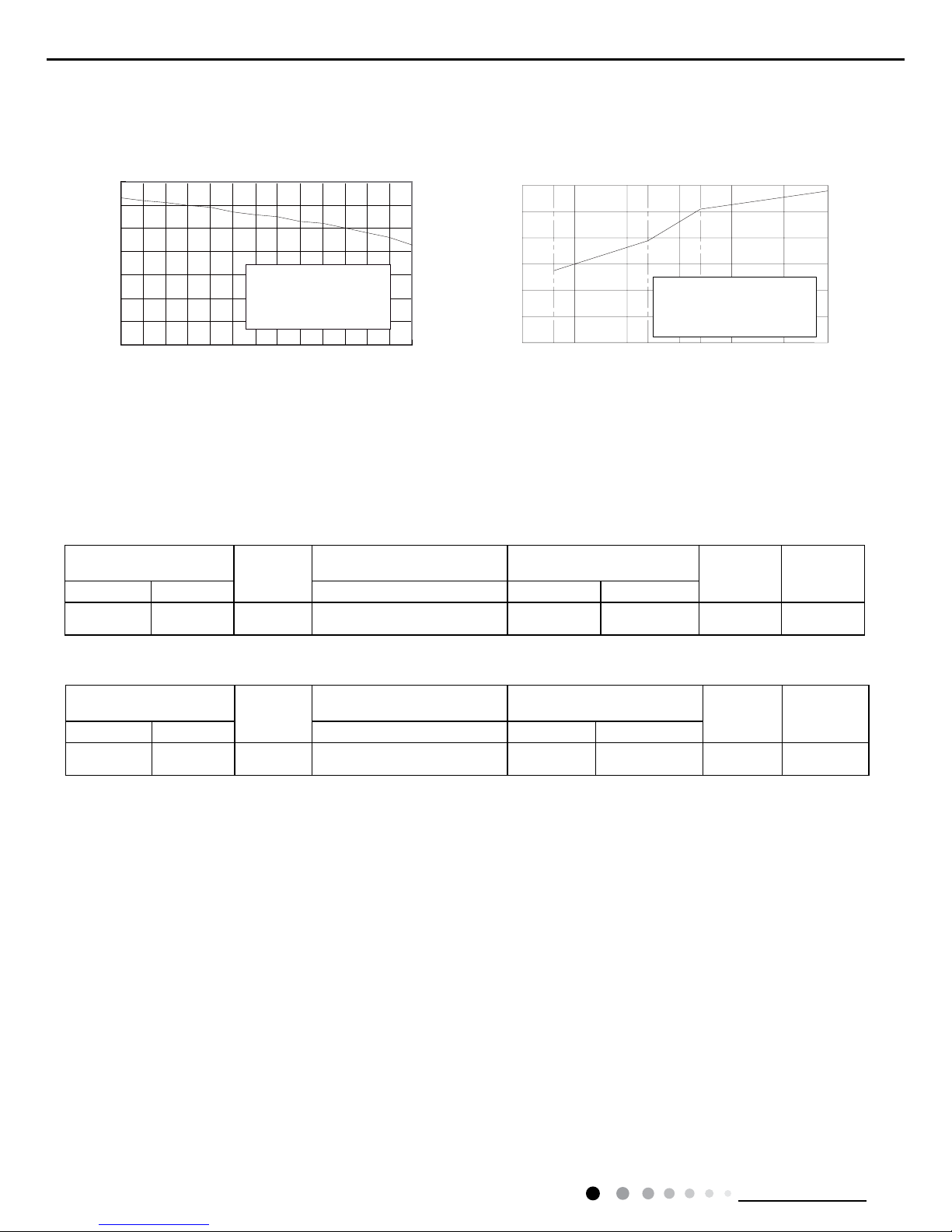
2.2 Capacity Curve in Different Outdoor Temperature
2.3 Cooling and Heating Data Sheet in Rated Frequency
Heating
Rated heatling condition(°C)
(DB/WB)
Model
Pressure of gas pipe connecting
indoor and outdoor unit
Inlet and outlet pipe temperature
of heat exchanger
Fan speed of
indoor unit
Fan speed of
outdoor unit
Indoor Outdoor P (MPa) T1 (°C) T2 (°C)
20/- 7/6 24K 3.5~3.8
in:75~85
out:37~43
in:1~3
out:2~5
Super High High
40
50
60
70
80
90
100
110
32 33 34 35 36 37 38 39 40 41 42 43 44 45
Outdoor temp.( ) Outdoor temp.( )
)
%
(
o i t a r y t i c a p a
C
)%(oitar yticapaC
Condition
Indoor:DB27
°C
WB19
°C
°C
°C
Indoor air flow: Super High
Pipe length:5m
157-7 -5 02
24
0
20
40
60
80
100
120
-10510
Condition Heating
Indoor:DB20
°C
Indoor air flow: Super High
Pipe length:5m
Cooling Heating
Rated cooling condition(°C)
(DB/WB)
Model
Pressure of gas pipe connecting
indoor and outdoor unit
Inlet and outlet pipe temperature
of heat exchanger
Fan speed of
indoor unit
Fan speed of
outdoor unit
Indoor Outdoor P (MPa) T1 (°C) T2 (°C)
27/19 35/24 24K 0.85~1.0
in:8~11
out:11~14
in:75~85
out:37~43
Super High High
Cooling
Instruction:
T1: Inlet and outlet pipe temperature of evaporator
T2: Inlet and outlet pipe temperature of condenser
P: Pressure at the side of big valve
Connection pipe length: 5m.
5
Technical Information
Service Manual
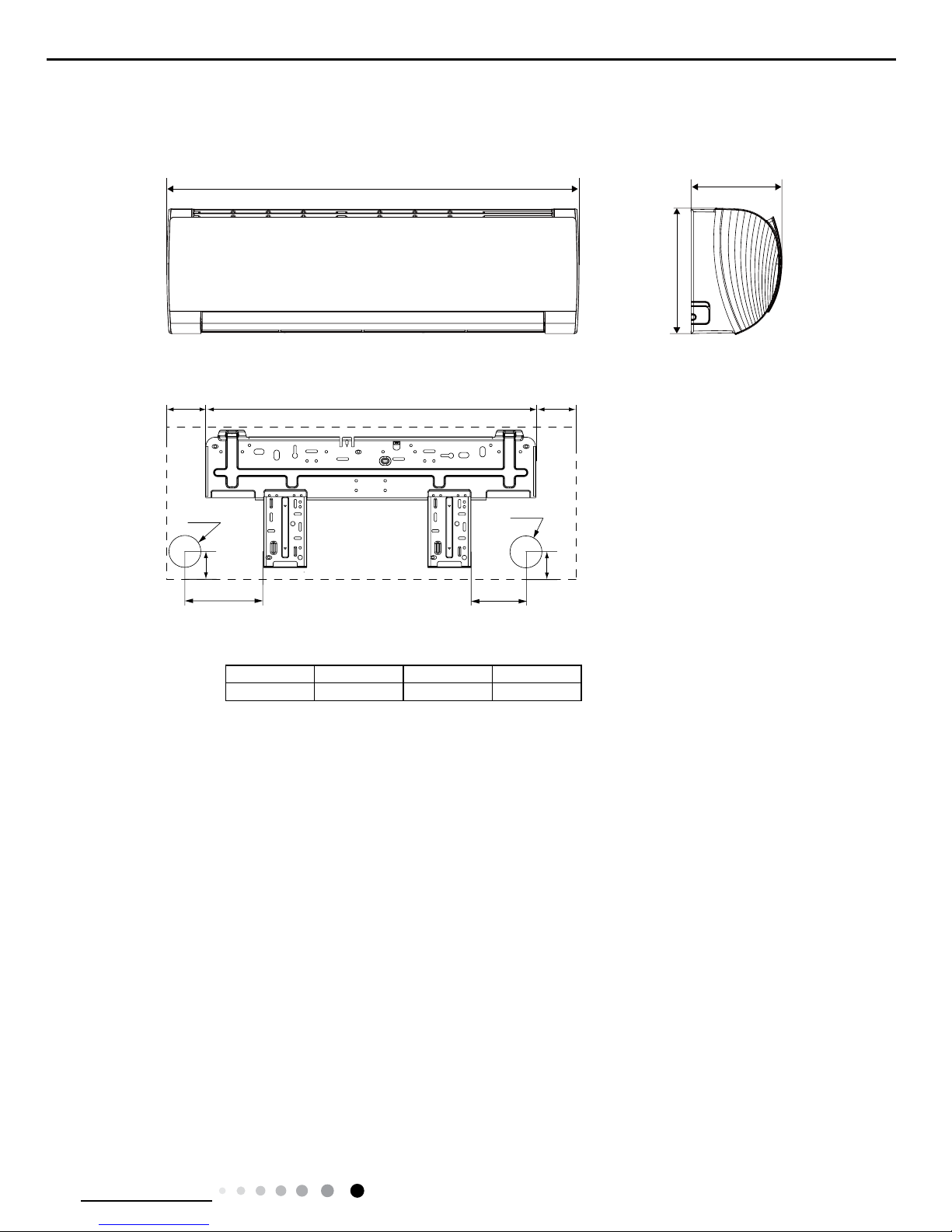
3. Outline Dimension Diagram
3.1 Indoor Unit
Unit:mm
125.5 685 202.5
140
190
38
Φ55
Φ55
38
W
H
D
MODEL W H D
24K 1013 307 221
6
Technical Information
Service Manual
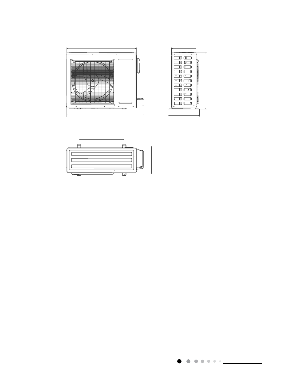
Unit:mm
3.2 Outdoor Unit
913
378
847
680
549
843
300
7
Technical Information
Service Manual
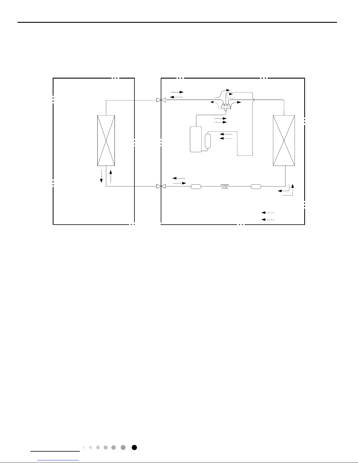
4. Refrigerant System Diagram
Cooling and heating model
Connection pipe specication:
Liquid pipe:1/4" (6mm)
Gas pipe:1/2" (12mm)
Indoor unit
Outdoor unit
Indoor unit
Outdoor unit
COOLING
HEATING
Accumlator
4-Way valve
COOLING
Discharge
Suction
Discharge
Suction
Heat
exchanger
(evaporator)
Heat
exchanger
(evaporator)
Heat
exchanger
(condenser)
Heat
exchanger
(condenser)
Valve
Valve
Valve
Valve
Liquid pipe
side
Gas pipe
side
Liquid pipe
side
Gas pipe
side
Compressor
Accumlator
Compressor
Strainer
Strainer
Capillary
StrainerCapillary
8
Technical Information
Service Manual
Symbol Symbol Color Symbol Symbol Color Symbol Name
WH White GN Green CAP Jumper cap
YE Yellow BN Brown COMP Compressor
RD Red BU Blue Grounding wire
YEGN Yellow/Green BK Black / /
VT Violet OG Orange / /
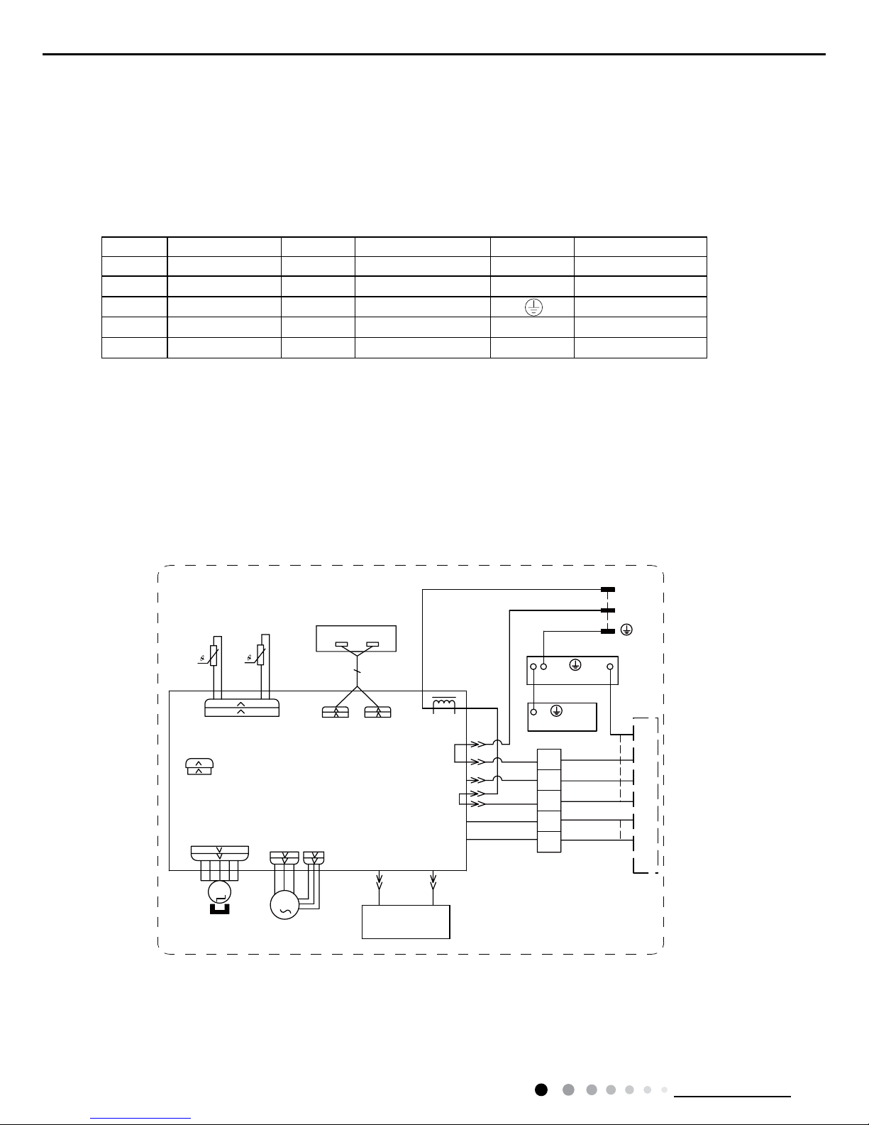
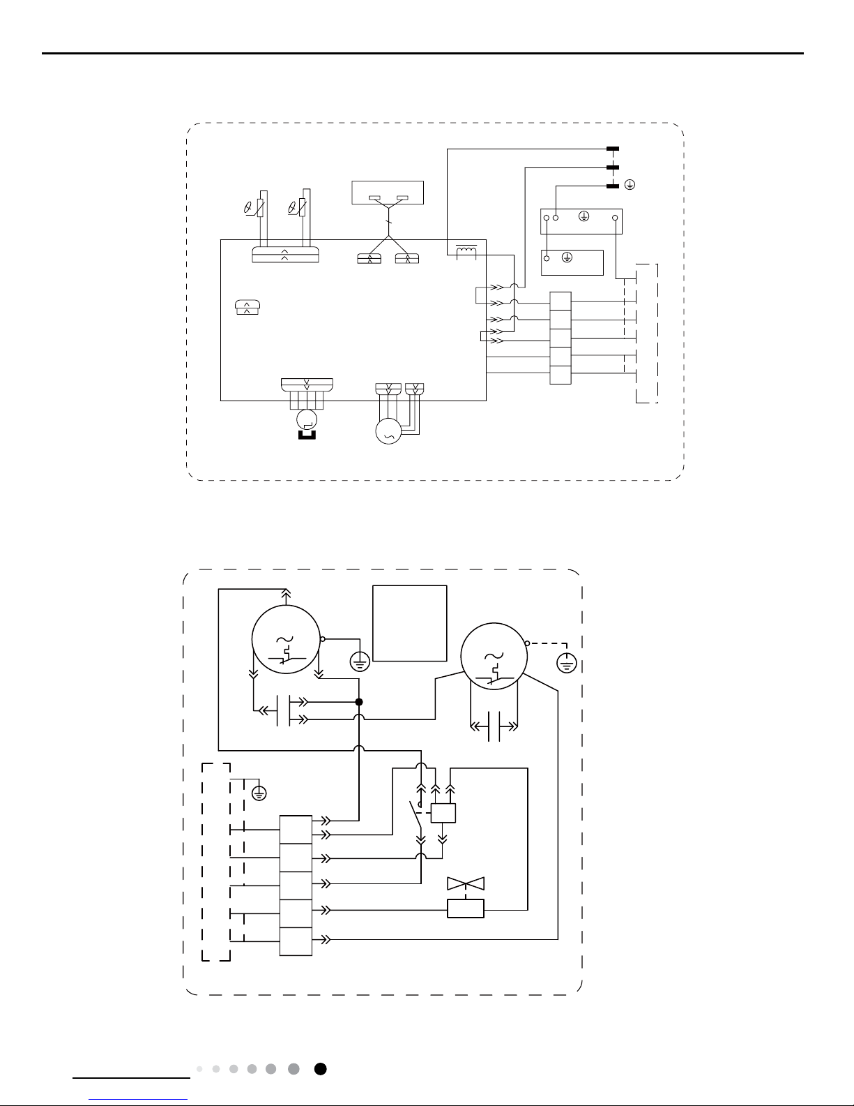
5. Electrical Part
5.1 Wiring Diagram
● Indoor Unit
●Instruction
Note: Jumper cap is used to determine fan speed and the swing angle of horizontal lover for this model.
;7
%85'
&2/'3/$60$
*(1(5$725
+($/7+1
+($/7+/
1
0
)$102725
3*
3*)
67(33,1*
0
6:,1*8'
6:,1*
',63/$<
',63
$3
',63
/$&/
32:(5
&211(&7,1*
%/2&.
7(50,1$/
&$%/(
/
1
<(*1*1
1
%8
%.
/
%8:+
%1%.
35,17('&,5&8,7%2$5'
287'22581,7
:$<
2)$1
($57+3/$7(
3(
3(
(9$325$725
<(*1
<(*1
97
2*
%8
%.
%1
2*
&203
%1
97
-803
&$3
',63/$<%2$5'
5(&(,9(5$1'
$3
76(1625
7(03
6(1625
7(03
6(1625
57
57
5220
78%(
02725
63632437
GWH24ACD-K3NNA1A/I(CA497N00600/CA497N00601)
9
Technical Information
Service Manual
6363243702
6363344001
These wiring diagrams are subject to change without notice; please refer to the one supplied with the unit.
GWH24ACD-K3NNA1A/I(CA497N00602/CA497N00603)
$&&217$&725
<(*1
3(
<(*1
<(*1
97
%.
%1
97
-
%8
%8
%.
%8
5'
%1
&
&$3
)$102725
0
&203
%.
<(
%8
%8
&$3
&
&
50
6
&203
:$<9$/9(
<9
.0
%/2&.
7(50,1$/
;7
2*
97
%.
%1
%8
,1'22581,7
1
3(
3(
2*:+
%1
7
/
$
$
127(0RWRU
JURXQGRQO\
DSSOLHVWR
WKHLURQ
VKHOOPRWRU
● Outdoor Unit
02725
57
57
6(1625
7(03
6(1625
7(03
76(1625
$3
5(&(,9(5$1'
',63/$<%2$5'
&$3
-803
97
%1
&203
2*
%1
%.
%8
2*
97
<(*1
<(*1
(9$325$725
3(
3(
($57+3/$7(
2)$1
287'22581,7
35,17('&,5&8,7%2$5'
%1%.
%8:+
/
%.
%8
1
<(*1*1
1
/
&$%/(
7(50,1$/
%/2&.
&211(&7,1*
32:(5
/$&/
',63
$3
',63
',63/$<
6:,1*
6:,1*8'
0
67(33,1*
3*)
3*
)$102725
0
1
;7
78%(
5220
:$<

10
Technical Information
Service Manual
5.2 PCB Printed Diagram
● Top view
● Bottom view
1Interface of compressor
2Interface of live wire
3Interface of neutral wire
4
Interface of neutral wire for
cold plasma
5Interface of PG motor
6Interface of outdoor fan
7Interface of 4-way valve
8
Interface of live wire of cold
plasma
9Interface of up&down swing
10
Feedback interface of PG
motor
11 Interface of left&right swing
12 Jumper
13
Interface of temperature
sensor
14 Interface of display board
1
2
3
5678
9
10
11
12
13
14
4
11
Technical Information
Service Manual
6. Function and Control
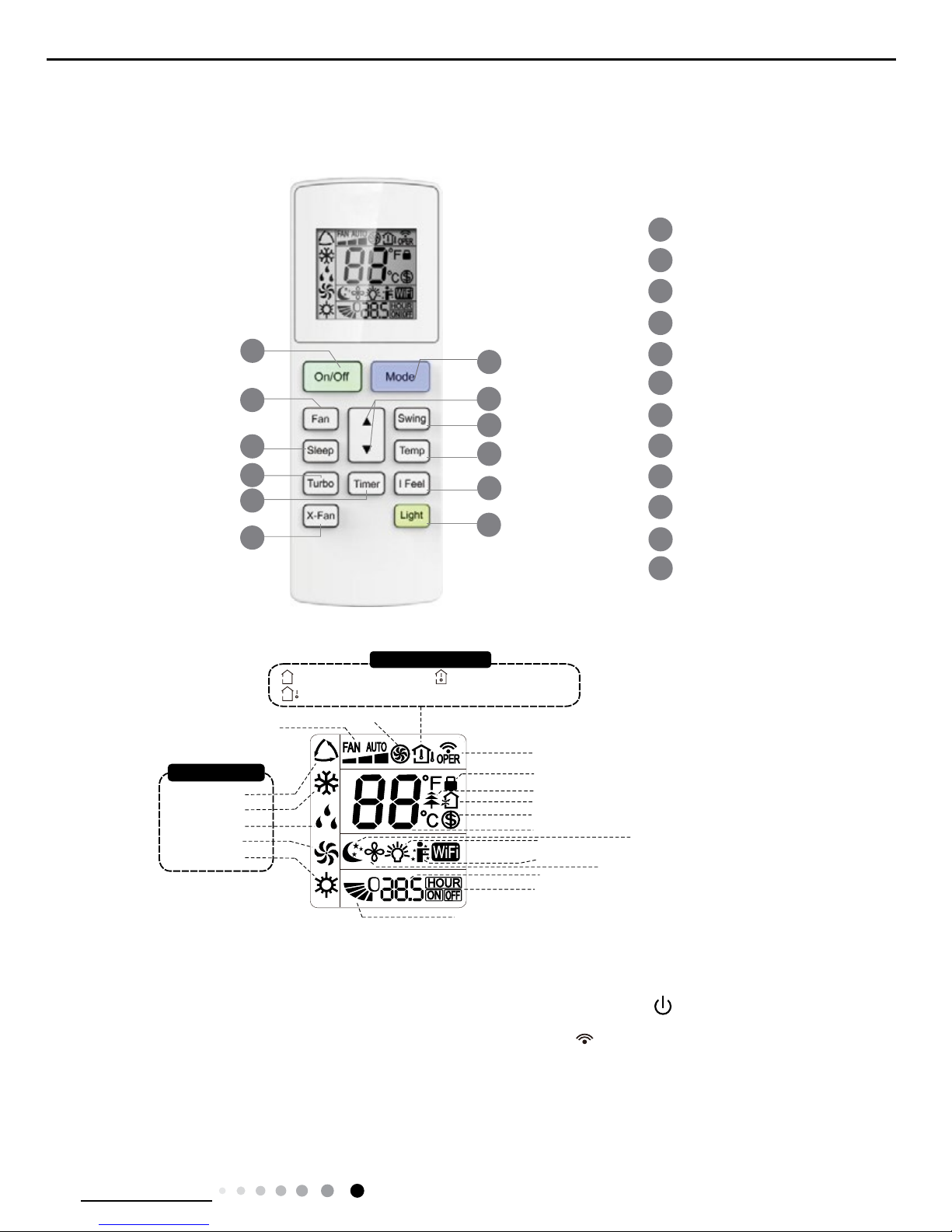
6.1 Remote Controller Introduction
Icon Display on Remote Controller
Operation introduction of remote controller
Buttons on Remote Controller
1
2
5
4
6
7
8
11
12
9
On/Off button
▲/ button
3
Fan button
Swing button
X-Fan button
Turbo button
Light button
10
Temp button
I Feel button
Timer button
Sleep button
Mode button
▲
2
5
7
9
4
12
3
1
6
8
10
11
Send signal
Turbo mode
8ć heating function
Set temperature
Set time
TIMER ON /TIMER OFF
Child lock
Up & down swing
Set fan speed
Light function
Temp. display type
:Set temp.
:Outdoor ambient temp.
:Indoor ambient temp.
Sleep mode
Heat mode
Fan mode
Dry mode
Cool mode
Auto mode
Operation mode
I feel function
X-fan mode
health function
ventilation operation
● This is a general use remote controller, it could be used for the air conditioners with multifunction; For some function, wh
ich
the model doesn't have, if press the corresponding button on the remote controller that the unit will keep the original running
status
.
●After putting through the power, the air conditioner will give out a sound.Operation indictor " " is ON (red indicator). Af
ter that,
you can operate the air conditioner by using remote controller
.
● Under on status, pressing the button on the remote controller, the signal icon " "on the display of remote controller wi
ll
blink once and the air conditioner will give out a “de” sound, which means the signal has been sent to the air conditioner
.
● Under off status, set temperature and clock icon will be displayed on the display of remote controller (If timer on, timer of
f and
light functions are set, the corresponding icons will be displayed on the display of remote controller at the same time); Under
on
status, the display will show the corresponding set function icons.
12
Technical Information
Service Manual
1. ON/OFF button
2. MODE button
3. F
AN button
6. SLEEP button
5. SWING button
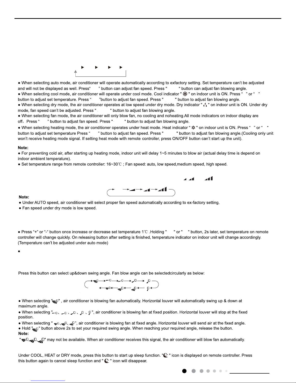
Press this button to turn on the unit. Press this button again to turn off the unit.
Each time you press this button,a mode is selected in a sequence that goes from AUTO, COOL, DRY, FAN, and HEAT *,
as the following:
AUTO COOL DRY FAN
HEAT
*
* Note: Only for models with heating function.
This button is used for setting Fan Speed in the sequence that goes from AUTO,
, to , then back to Auto.
4.▲ / button
▲
▲Press / button to increase/decreaseset temperature.In AUTO mode,set temperature is not adjustable.
▲
Press this button to set up & down swing angle.
Auto
▲
▲
▲
▲
▲
▲
(horizontal louvers
stops at current position)
no display
Fan
Fan
Swing
Swing
Swing
Swing
Swing
Fan
Fan
When setting Timer On or Timer Off, press ▲ or ▼ button to adjust the time. (See TIMER Button for setting details)
13
Technical Information
Service Manual
7.
TEMP button
8. TURBO button
9. I FEEL button
10. Timer button
11. X-FAN button
12. LIGHT button
NOTICE:
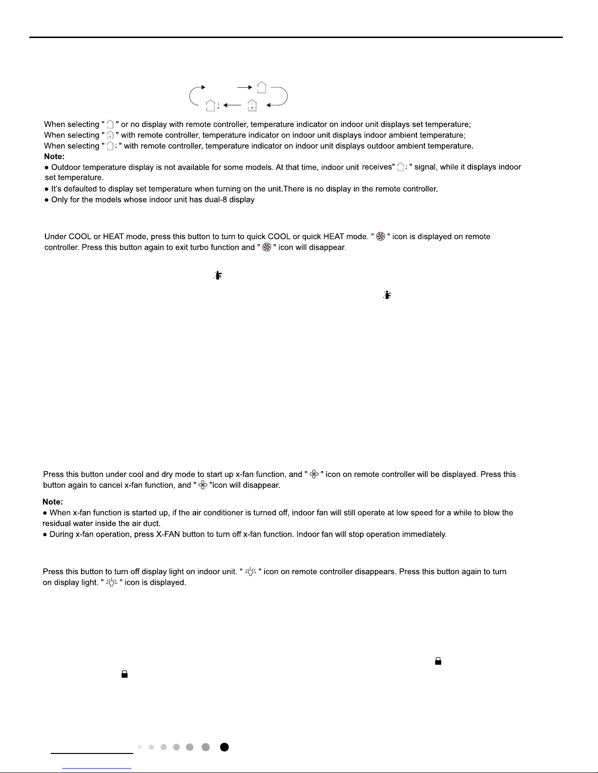
Press this button, you can see indoor set temperature, indoor ambient temperature
on indoor unit’s display. The setting
on remote controller is selected circularly as below:
no display
Press this button to activate / deactivate the Turbo function.
Turn on the display's light and press this button again to turn off the display's
light.
As for the detailed content of remote controller, please refer to QR code on the cover.
Function introduction for combination buttons
Press " " and " "
buttons simultaneously 3s to lock or unlock the keypad. If the remote
pressing any button, blinks three times.
controller is locked, is displayed. In this case,
▲
Combination of "" and " " buttons: About lock
▲
▲
▲
About switch between Fahrenheit and centigradeCombination of "MODE" and " " buttons:
▲
At unit OFF, press "MODE" and " " buttons simultaneously to
switch between ć and .
▲
(NOTE:X-FAN is the alternative expression of BLOW for the purpose of understanding.)
● When unit is on, press this button to set Timer Off. OFF and HOUR icon will be blinking. Within 5s, press ▲ or ▼ button to adjust the
time for Timer Off. Pressing ▲ or ▼ button once will increase or decrease the time by 0.5h. Hold ▲ or ▼ button for 2s, time will change
quickly. Release the button after your required set time is reached. Then press TIMER button to confirm it. OFF and HOUR icon will
stop blinking.
● When unit is off, press this button to set Timer On. ON and HOUR icon will be blinking. Within 5s, press ▲ or ▼ button to adjust the
time for Timer On. Pressing ▲ or ▼ button once will increase or decrease the time by 0.5h. Hold ▲ or ▼ button for 2s, time will
change quickly. Release the button after your required set time is reached. Then press TIMER button to confirm it. ON and HOUR icon
will stop blinking.
● Cancel Timer On/Off: If Timer function is set up, press TIMER button once to cancel this function.
Note:
● Range of time setting is: 0.5~24h
● The interval between two motions can't exceed 5s, otherwise the remote controller
will exit setting status.
Press this button to start I FEEL function and " " will be displayed on the remote controller. After this function is set, the remote
controller will send the detected ambient temperature to the controller and the unit will automatically adjust the indoor temperature
according to the detected temperature. Press this button again to close I FEEL function and " " will disappear.
14
Technical Information
Service Manual
8. TURBO button
9. I FEEL button
10. Timer button
11. X-FAN button
12. LIGHT button
NOTICE:
Press this button, you can see indoor set temperature, indoor ambient temperature
on indoor unit’s display. The setting
on remote controller is selected circularly as below:
no display
Press this button to activate / deactivate the Turbo function.
Turn on the display's light and press this button again to turn off the display's
light.
As for the detailed content of remote controller, please refer to QR code on the cover.
Function introduction for combination buttons
Press " " and " "
buttons simultaneously 3s to lock or unlock the keypad. If the remote
pressing any button, blinks three times.
controller is locked, is displayed. In this case,
▲
Combination of "" and " " buttons: About lock
▲
▲
▲
About switch between Fahrenheit and centigradeCombination of "MODE" and " " buttons:
▲
At unit OFF, press "MODE" and " " buttons simultaneously to
switch between ć and .
▲
Nixie tube on the remote controller displays
"SE"
. Repeat the operation to quit the function.
Combination of "TEMP" and "TIMER" buttons: About Energy-saving Function
Press "TEMP" and "TIMER" simultaneously in COOL mode to start e nergy-saving function.
(46 if Fahrenheit is adopted). Repeat the operation to quit the function.
Combination of "TEMP" and "TIMER" buttons:
About 8
ć
Heating Function
Press "TEMP" and "
TIMER
" simultaneously in HEAT mode to start 8
ć
Heating Function
Nixie tube on the remote controller displays "
"
and a selected temperature of
"8ć".
(NOTE:X-FAN is the alternative expression of BLOW for the purpose of understanding.)
● When unit is on, press this button to set Timer Off. OFF and HOUR icon will be blinking. Within 5s, press ▲ or ▼ button to adjust the
time for Timer Off. Pressing ▲ or ▼ button once will increase or decrease the time by 0.5h. Hold ▲ or ▼ button for 2s, time will change
quickly. Release the button after your required set time is reached. Then press TIMER button to confirm it. OFF and HOUR icon will
stop blinking.
● When unit is off, press this button to set Timer On. ON and HOUR icon will be blinking. Within 5s, press ▲ or ▼ button to adjust the
time for Timer On. Pressing ▲ or ▼ button once will increase or decrease the time by 0.5h. Hold ▲ or ▼ button for 2s, time will
change quickly. Release the button after your required set time is reached. Then press TIMER button to confirm it. ON and HOUR icon
will stop blinking.
● Cancel Timer On/Off: If Timer function is set up, press TIMER button once to cancel this function.
Note:
● Range of time setting is: 0.5~24h
● The interval between two motions can't exceed 5s, otherwise the remote controller
will exit setting status.
Press this button to start I FEEL function and " " will be displayed on the remote controller. After this function is set, the remote
controller will send the detected ambient temperature to the controller and the unit will automatically adjust the indoor temperature
according to the detected temperature. Press this button again to close I FEEL function and " " will disappear.
WIFI Function
Press "MODE" and "TURBO" button simultaneously to turn on or turn off WIFI function. When WIFI function is turned on, the
icon will be displayed on remote controller; Long press "MODE" and "TURBO" buttons simultaneously for 10s, remote controller wi
ll send
WIFI reset code and then the WIFI function will be turned on. WIFI function is defaulted ON after energization of the remote controller.
● This function is only available for some models.
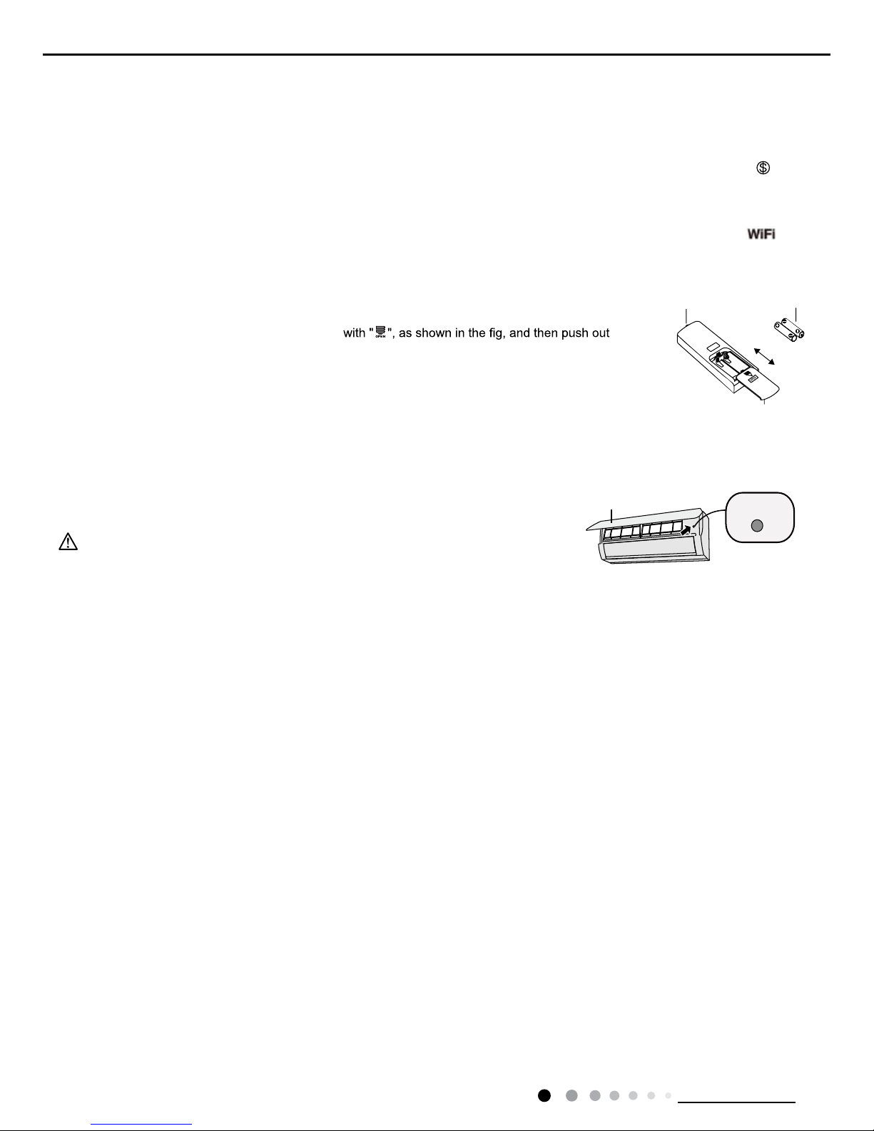
Replacement of batteries in remote controller
Emergency operation
If remote controller is lost or damaged, please use auxiliary button to turn on or turn off the air conditioner.
When the air conditioner is turned on, it will operate under auto mode.
aux. button
panel
WARNING:
Use insulated object to press the auto button
As shown in the fig.Open panel ,press aux.button to turn on or turn off the air conditioner.
The operation in details are as below:
1. Press the back side of remote controller marked
the cover of battery box along the arrow direction.
2. Replace two 7# (AAA 1.5V) dry batteries, and make sure the position of "+" polar and "-" polar
are correct.
3. Reinstall the cover of battery box.
signal sender battery
Cover of battery box
remove
reinstall
15
Technical Information
Service Manual
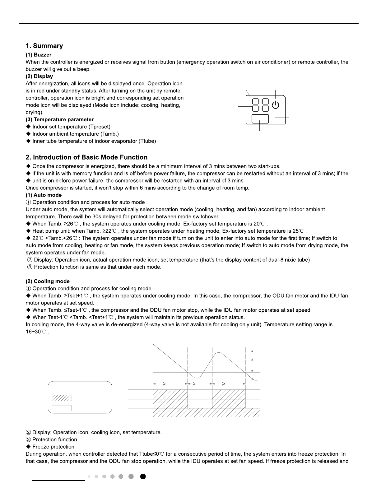
6.2 Brief Description of Modes and Functions
Indicates operation
Indicates stop
Tpreset +1 ˚C
Tpreset –1 ˚C
Compressor
Outdoor fan motor
Indoor fan motor
Graphic instruction:
(Same as below)
Tamb.
Stop cooling
Start cooling
Original operating status
6 min. 3 min. 6 min.
Set fan speed
Temp
.
indicato
r
Display
receiver
window
Power indicatior
Display
16
Technical Information
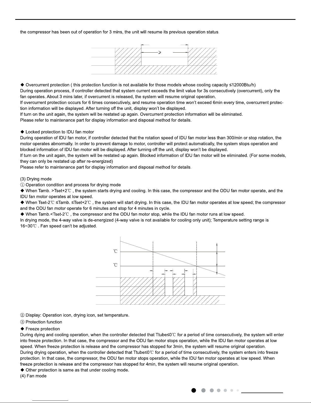
Service Manual
T
preset
T
amb.
+2
T
preset-
2
Cooling
Drying
Stop
6 min
6min.
4min.
4min.
Compressor
Low speed
Outdoor fan motor
Indoor fan motor
Freeze protection period
Compressor
Outdoor fan motor
Indoor fan motor
3 min
Set fan speed
17
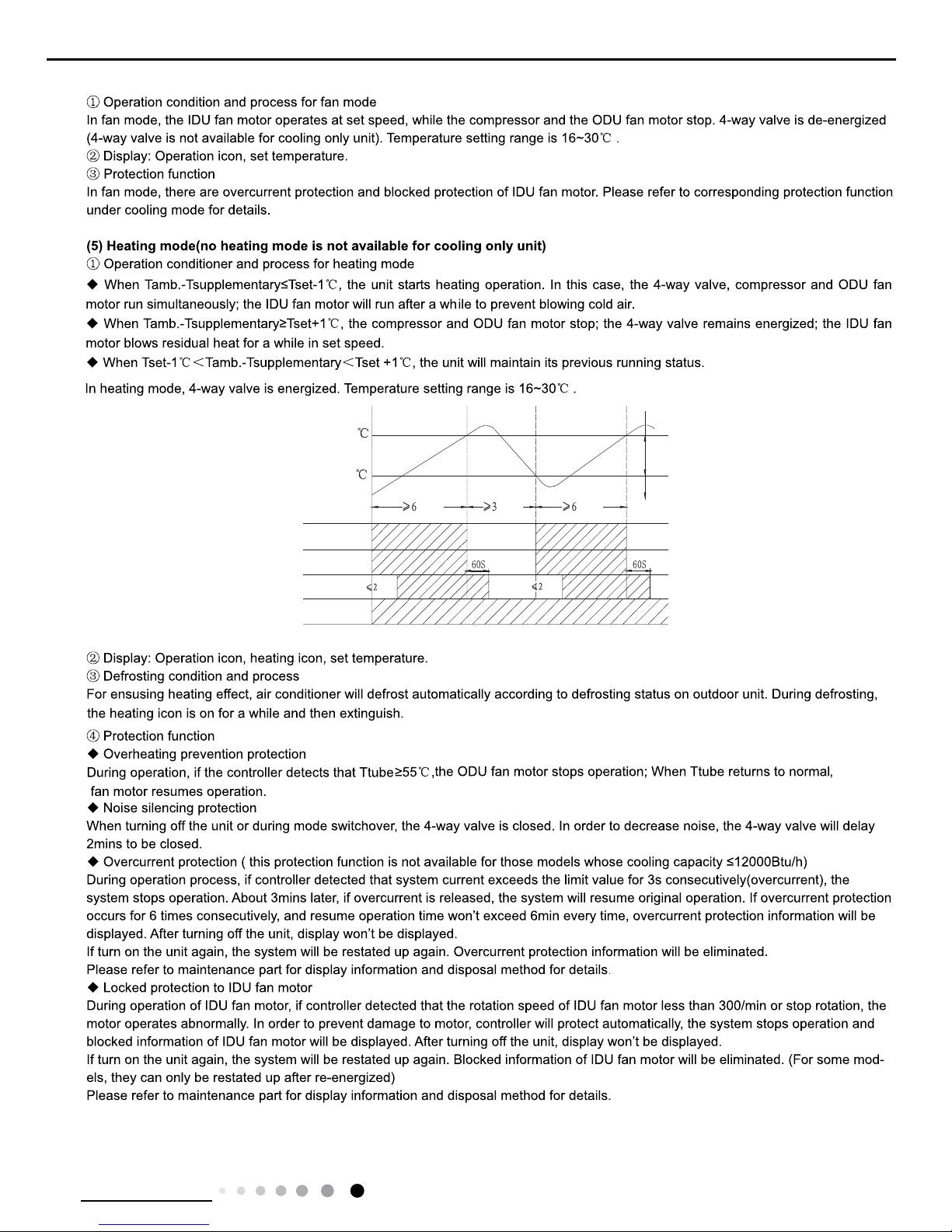
Technical Information
Service Manual
T
preset
+4
T
preset
+2
valve
Outdoor unit
Intdoor unit
Compressor
min.
min.
min.
T
amb
.
.nim.nim
Set fan speedSet fan speed
Reversing
Stop heating
Original operating status
Start heating
 Loading...