

Gree GWH24YE-K6DNA1A, GWH24YE-K6DNA2A, GWH18YD-K6DNA1A/I, GWH18YD-K6DNA2A/I, GWH18YD-K6DNA1A/O Service Manual

GREE ELECTRIC APPLIANCES,INC.OF ZHUHAI
Change for Life
Service Manual
Models: GWH24YE-K6DNA1A
GWH24YE-K6DNA2A
(Refrigerant R32)

Service Manual
Table of Contents
Table of Contents
Part
Ⅰ
: Technical Information
.......................................................................1
1. Summary
......................................................................................................................1
2. Specications
..........................................................................................................2
2.1 Specication Sheet ...........................................................................................................2
2.2 Operation Characteristic Curve ........................................................................................4
2.3 Capacity Variation Ratio According to Temperature .........................................................4
2.4 Cooling and Heating Data Sheet in Rated Frequency .....................................................5
2.5 Noise Curve ......................................................................................................................5
3. Outline Dimension Diagram
.........................................................................................6
3.1 Indoor Unit ........................................................................................................................6
3.2 Outdoor Unit .....................................................................................................................7
4. Refrigerant System Diagram
......................................................................8
5. Electrical Part
...........................................................................................................9
5.1 Wiring Diagram .................................................................................................................9
5.2 PCB Printed Diagram ..................................................................................................... 11
6. Function and Control
......................................................................................13
6.1 Remote Controller Introduction .....................................................................................13
6.2 GREE+ App Operation Manual ......................................................................................18
6.3 Ewpe Smart App Operation Manual ...............................................................................19
6.4 Brief Description of Modes and Functions ......................................................................20
Part
Ⅱ
: Installation and Maintenance
.................................................29
7. Notes for Installation and Maintenance
..........................................29
8. Installation
................................................................................................................33
8.1 Installation Dimension Diagram ......................................................................................33
8.2 Installation Parts-checking ............................................................................................35
8.3 Selection of Installation Location ....................................................................................35
8.4 Requirements for electric connection .............................................................................35
8.5 Installation of Indoor Unit ................................................................................................35
8.6 Installation of Outdoor unit .............................................................................................38
8.7 Vacuum Pumping and Leak Detection ...........................................................................39
8.8 Check after Installation and Test operation ....................................................................39

Service Manual
Table of Contents
9. Maintenance
............................................................................................................41
9.1 Error Code List ...............................................................................................................41
9.2 Troubleshooting for Main Malfunction ............................................................................46
9.3 Troubleshooting for Normal Malfunction .........................................................................59
10. Exploded View and Parts List
..............................................................61
10.1 Indoor Unit ....................................................................................................................61
10.2 Outdoor Unit .................................................................................................................64
11. Removal Procedure
.......................................................................................66
11.1 Removal Procedure of Indoor Unit ...............................................................................66
11.2 Removal Procedure of Outdoor Unit ............................................................................71
Appendix:
........................................................................................................................78
Appendix 1: Reference Sheet of Celsius and Fahrenheit ....................................................78
Appendix 2: Conguration of Connection Pipe .....................................................................78
Appendix 3: Pipe Expanding Method ...................................................................................79
Appendix 4: List of Resistance for Temperature Sensor ......................................................80
1
Service Manual
Technical Information
1. Summary
Part
Ⅰ
: Technical Information
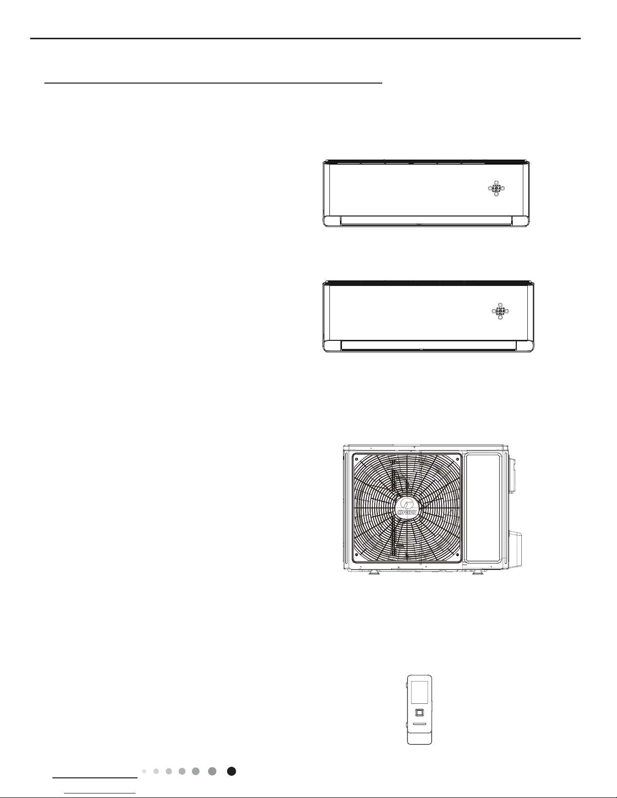
Indoor Unit
GWH24YE-K6DNA1A/I
GWH24YE-K6DNA2A/I
Remote Controller
YAG1FB2(WiFi)
Outdoor Unit
GWH24YE-K6DNA1A/O
FAN
MODE
ON/OF
F
+-
2
Service Manual
Technical Information
2. Specications
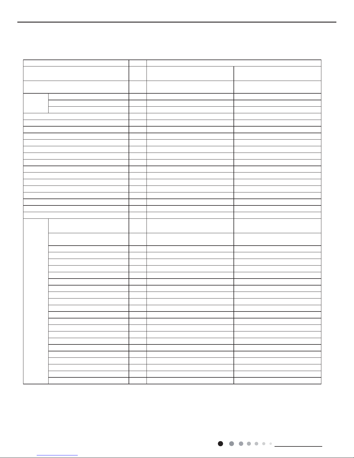
2.1 Specication Sheet
Parameter Unit Value
Model
GWH24YE-K6DNA1A
GWH24YE-K6DNA2A
GWH24YE-K6DNA1A
GWH24YE-K6DNA2A
Product Code
CB437001400
CB466001400
CB437001401
CB466001401
Power
Supply
Rated Voltage V
~
220-240 220-240
Rated Frequency Hz 50 50
Phases 1 1
Power Supply Mode Outdoor Outdoor
Cooling Capacity(Min~Max) W 7000(1100~9050) 7000(1100~9050)
Heating Capacity(Min~Max) W 7200(1700~10100) 7200(1700~10100)
Cooling Power Input(Min~Max) W 2000(400~3700) 2000(400~3700)
Heating Power Input(Min~Max) W 1845(450~3800) 1845(450~3800)
Cooling Current Input A 9.15 9.15
Heating Current Input A 8.44 8.44
Rated Input W 3800 3800
Rated Current A 16.42 16.42
Air Flow Volume(Min~Max) m3/h 1250/1100/1000/950/900/850/750 1250/1100/1000/950/900/850/750
Dehumidifying Volume L/h 2.4 2.4
EER W/W 3.5 3.5
COP W/W 3.9 3.9
SEER W/W 7 7
HSPF W/W / /
Application Area m
2
27-42 27-42
Indoor
Unit
Indoor Unit Model
GWH24YE-K6DNA1A/I
GWH24YE-K6DNA2A/I
GWH24YE-K6DNA1A/I
GWH24YE-K6DNA1A/I
Indoor Unit Product Code
CB437N01400
CB466N01400
CB437N01401
CB437N01400
Fan Type Cross-ow Cross-ow
Fan Diameter Length(DXL) mm Φ108X830 Φ108X830
Cooling Speed(Min~Max) r/min 1250/1100/1000/950/900/850/800/600 1250/1100/1000/950/900/850/800/600
Heating Speed(Min~Max) r/min 1400/1250/1100/1050/1000/900/850 1400/1250/1100/1050/1000/900/850
Fan Motor Power Output W 50 50
Fan Motor RLA A 0.35 0.35
Fan Motor Capacitor μF / /
Evaporator Form Aluminum Fin-copper Tube Aluminum Fin-copper Tube
Evaporator Pipe Diameter mm Ф7 Ф7
Evaporator Row-n Gap mm 1.5 1.5
Evaporator Coil Length (LXDXW) mm 850X25.4X342.9 850X25.4X342.9
Swing Motor Model MP35CP MP35CP
Swing Motor Power Output W 2.5 2.5
Fuse Current A 3.15 3.15
Sound Pressure Level(Min~Max) dB (A) 49/47/44/42/40/38/36 49/47/44/42/40/38/36
Sound Power Level(Min~Max) dB (A) 65/61/58/56/54/52/50 65/61/58/56/54/52/50
Dimension (WXHXD) mm 1101X327X249 1101X327X249
Dimension of Carton Box (LXWXH) mm 1164X402X339 1164X402X339
Dimension of Package(LXWXH) mm 1167X405X354 1167X405X354
Net Weight kg 16.5 16.5
Gross Weight kg 20 20
3
Service Manual
Technical Information
The above data is subject to change without notice. Please refer to the nameplate of the unit.
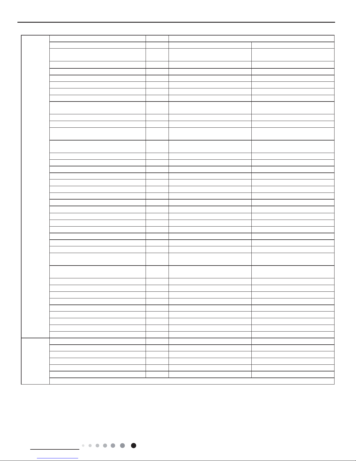
Outdoor
Unit
Outdoor Unit Model GWH24YE-K6DNA1A/O
Outdoor Unit Product Code CB437W01400 CB437W01401
Compressor Manufacturer
ZHUHAI LANDA COMPRESSOR
CO,LTD.
ZHUHAI LANDA COMPRESSOR
CO,LTD.
Compressor Model QXFS-D23ZX090A QXFS-D23ZX090A
Compressor Oil FW68DA FW68DA
Compressor Type Rotary Rotary
Compressor LRA. A 25 25
Compressor RLA A 11.5 11.5
Compressor Power Input W 2550 2550
Compressor Overload Protector
1NT11L-6233/HPC 115/95 /
KSD115ºC
1NT11L-6233/HPC 115/95 /
KSD115ºC
Throttling Method Electron expansion valve Electron expansion valve
Set Temperature Range ºC 16~30 16~30
Cooling Operation Ambient Temperature
Range
ºC -15~54 -15~54
Heating Operation Ambient Temperature
Range
ºC -15~24 -20~24
Condenser Form Aluminum Fin-copper Tube Aluminum Fin-copper Tube
Condenser Pipe Diameter mm Ф7 Ф7
Condenser Rows-n Gap mm 2-1.4 2-1.4
Condenser Coil Length (LXDXW) mm 935X38.1X660 935X38.1X660
Fan Motor Speed rpm 800 800
Fan Motor Power Output W 60 60
Fan Motor RLA A 0.58 0.58
Fan Motor Capacitor μF / /
Outdoor Unit Air Flow Volume m3/h 3200 3200
Fan Type Axial-ow Axial-ow
Fan Diameter mm Ф520 Ф520
Defrosting Method Automatic Defrosting Automatic Defrosting
Climate Type T1 T1
Isolation I I
Moisture Protection IPX4 IPX4
Permissible Excessive Operating Pressure
for the Discharge Side
MPa 4.3 4.3
Permissible Excessive Operating Pressure
for the Suction Side
MPa 2.5 2.5
Sound Pressure Level (H/M/L) dB (A) 60/-/- 60/-/-
Sound Power Level (H/M/L) dB (A) 70/-/- 70/-/-
Dimension(WXHXD) mm 963X700X396 963X700X396
Dimension of Carton Box (LXWXH) mm 1026X455X735 1026X455X735
Dimension of Package(LXWXH) mm 1029X458X750 1029X458X750
Net Weight kg 53 53
Gross Weight kg 57.5 57.5
Refrigerant R32 R32
Refrigerant Charge kg 1.7 1.7
Connection
Pipe
Connection Pipe Length m 5 5
Connection Pipe Gas Additional Charge g/m 50 50
Outer Diameter Liquid Pipe mm Ф6 Ф6
Outer Diameter Gas Pipe mm Ф16 Ф16
Max Distance Height m 10 10
Max Distance Length m 25 25
Note: The connection pipe applies metric diameter.
4
Service Manual
Technical Information
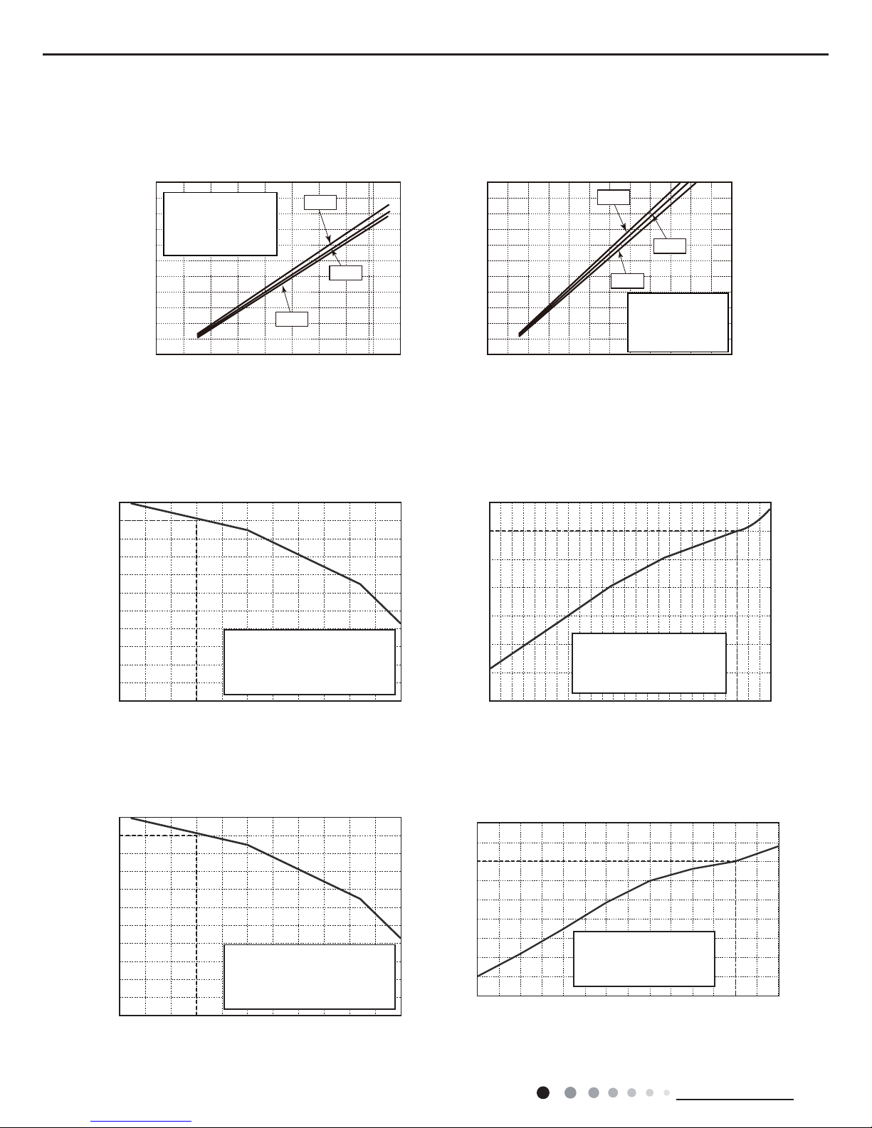
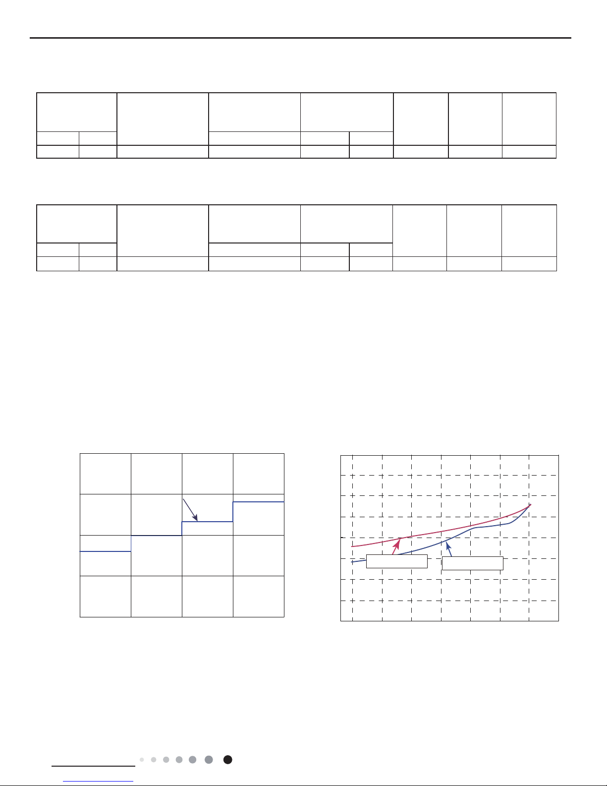
2.2 Operation Characteristic Curve
2.3 Capacity Variation Ratio According to Temperature
Cooling Heating
01020304050607090010 20 30 40 50 60 70 80 90 100
120
110
80
11
10
9
8
7
6
5
4
3
2
1
0
Compressor speed (rps)
11
10
9
8
7
6
5
4
3
2
1
0
Compressor speed (rps)
220V
230V
240V
220V
230V
240V
Conditions
Indoor: DB27°C/WB19°C
Outdoor: DB35°C/WB24°C
Indoor air flow: High
Pipe length: 5m
Conditions
Indoor: DB20°C/WB15°C
Outdoor: DB7°C/WB6°C
Indoor air flow: High
Pipe length: 5m
Cooling Heating
32 33 34 35 36 37 38 39 43 –15 –10 –5
40 41 42
100
105
95
90
85
80
75
70
65
60
55
50
110
100
90
80
70
60
50
40
05
71
0
Conditions
Indoor:DB27°C/WB19°C
Indoor air flow:Super High
Pipe length: 5m
Conditions
Indoor:DB20°C/WB15°C
Indoor air flow:Super High
Pipe length: 5m
Outdoor temp.(°C) Outdoor temp.(°C)
Capacity ratio (%)
Capacity ratio (%)
Cooling
Heating
32 33 34 35 36 37 38 39 43
40 41 42
100
105
95
90
85
80
75
70
65
60
55
50
Conditions
Indoor:DB27°C/WB19°C
Indoor air flow:Super High
Pipe length: 5m
Outdoor temp.(°C)
Capacity ratio (%)
30
40
50
60
70
80
90
100
110
120
10
-5 057-10-15-20
Outdoor temp.(oC)
Capacity ratio(%)
Conditions
Indoor:DB20°C/WB15°C
Indoor air flow:Super High
Pipe length: 5m
Cooling
Heating
Heating operation ambient temperature range is -15°C~24°C
Heating operation ambient temperature range is -20°C~24°C
5
Service Manual
Technical Information
2.4 Cooling and Heating Data Sheet in Rated Frequency
Rated cooling
condition(°C)
(DB/WB)
Model
Pressure of gas pipe
connecting indoor and
outdoor unit
Inlet and outlet pipe
temperature of heat
exchanger
Fan speed of
indoor unit
Fan speed of
outdoor unit
Compressor
frequency
(Hz)
Indoor Outdoor P (MPa) T1 (°C) T2 (°C)
27/19 35/24 24K 0.9 to 1.1 12 to 14 75 to 37 Super High High 72
Rated heating
condition(°C)
(DB/WB)
Model
Pressure of gas pipe
connecting indoor and
outdoor unit
Inlet and outlet pipe
temperature of heat
exchanger
Fan speed of
indoor unit
Fan speed of
outdoor unit
Compressor
frequency
(Hz)
Indoor Outdoor P (MPa) T1 (°C) T2 (°C)
20/- 7/6 24K 2.8 to 3.0 70 to 35 2 to 4 Super High High 77
Instruction:
T1: Inlet and outlet pipe temperature of evaporator
T2: Inlet and outlet pipe temperature of condenser
P: Pressure at the side of big valve
Connection pipe length: 5m.
Cooling:
Heating:
2.5 Noise Curve
Indoor side noise when blowing Outdoor side noise when blowing
Indoor fan motor rotating speed
Compressor frequency(Hz)
Noise/dB(A)
50
60
30
40
20
Low
Middle
High
Super High
24K
40
42
44
46
48
50
52
54
56
20 4030 50 60 70 80
90
Noise dB(A)
Cooling
Heating
6
Service Manual
Technical Information
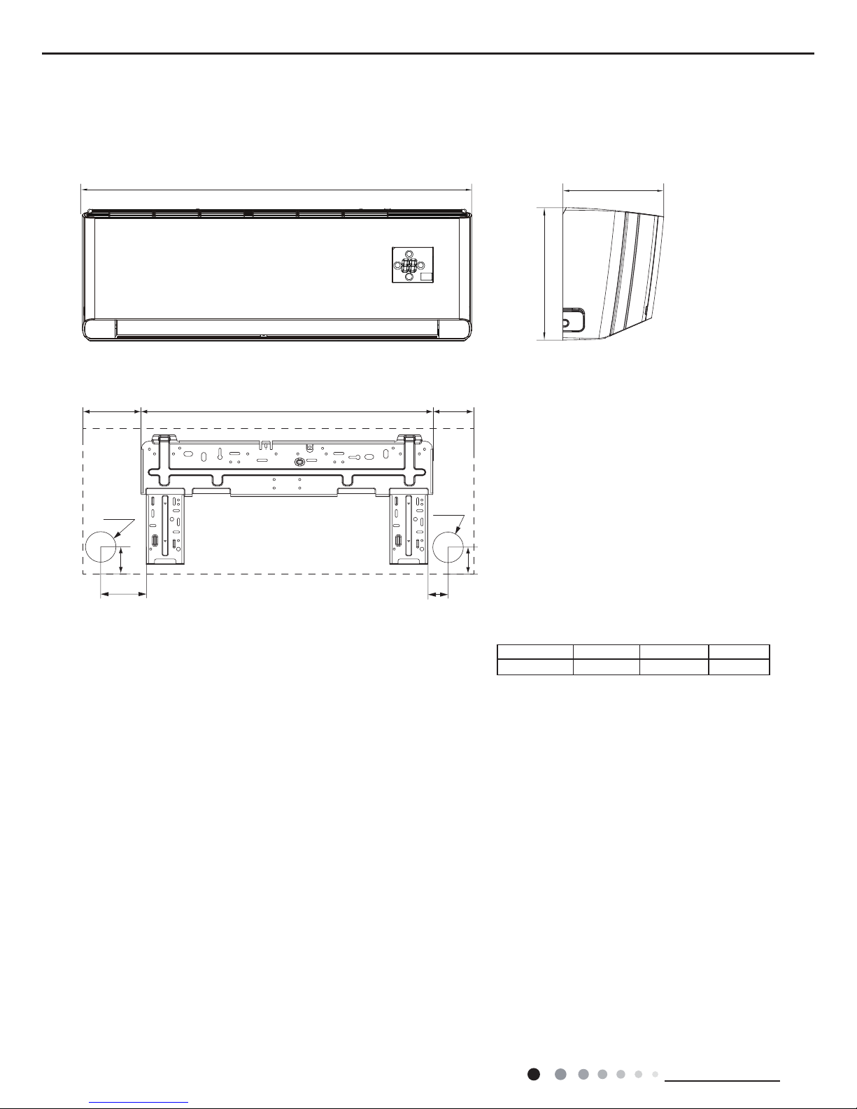
3. Outline Dimension Diagram
3.1 Indoor Unit
79
154
43
216 685 200
Φ70
Φ70
43
117 685 194
140
190
38
Φ55
Φ55
38
Unit:mm
W D
H
Models W H D
24K 1101 327 249
7
Service Manual
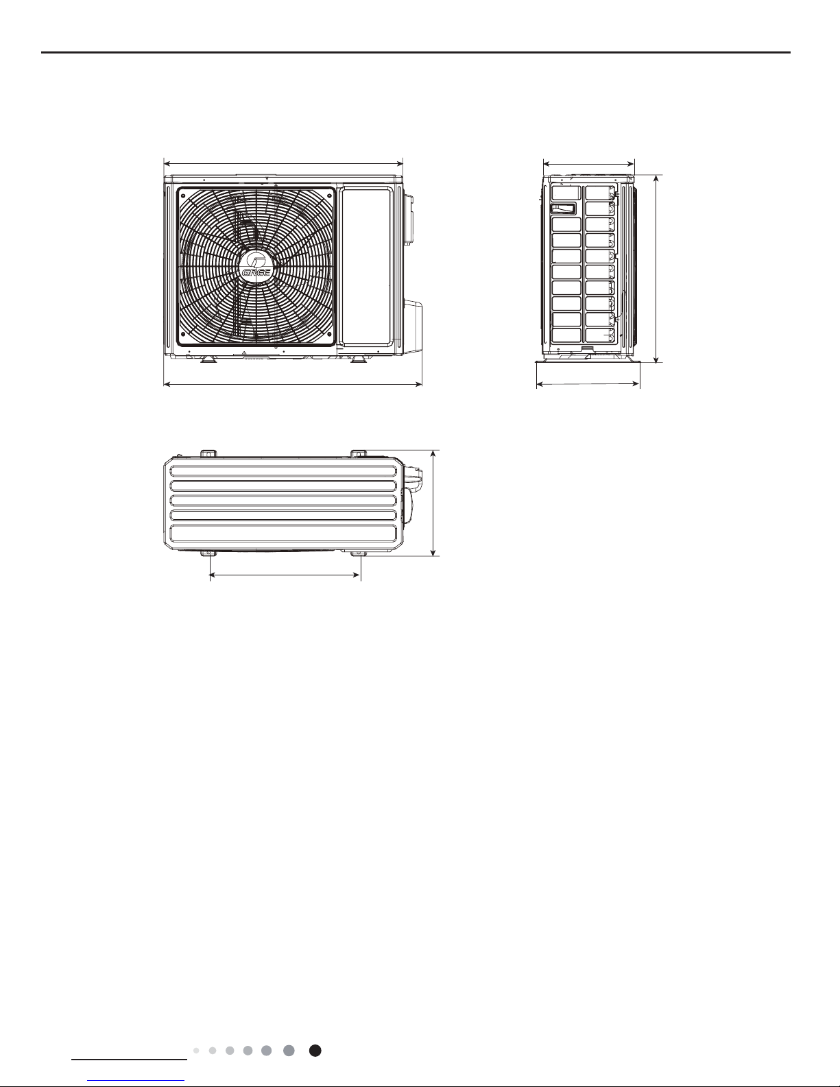
Technical Information
3.2 Outdoor Unit
963
892
700
396
560
341
396
Unit:mm
8
Service Manual
Technical Information
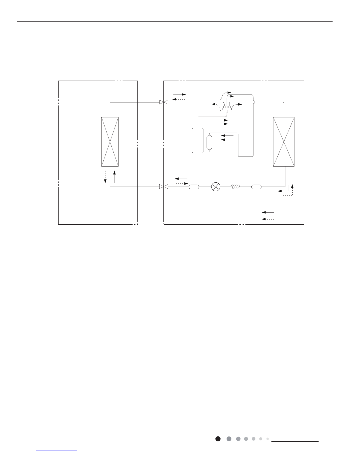
Indoor unit
Outdoor unit
Indoor unit
Outdoor unit
COOLING
HEATING
Accumlator
Accumlator
4-Way valve
COOLING
Discharge
Suction
Discharge
Suction
Heat
exchanger
(evaporator)
Heat
exchanger
(evaporator)
Heat
exchanger
(condenser)
Heat
exchang
(condenser)
Valve
Valve
Valve
Valve
Liquid pipe
side
Gas pipe
side
Liquid pipe
side
Gas pipe
side
Compressor
Compressor
Strainer
Strainer
Capillary
Strainer
Capillary
Electron
expansion
valve
Electron
expansion
valve
4. Refrigerant System Diagram
Connection pipe specication:
Liquid pipe:1/4" (6mm)
Gas pipe:5/8" (16mm)
Cooling and heating model
9
Service Manual
Technical Information
5. Electrical Part
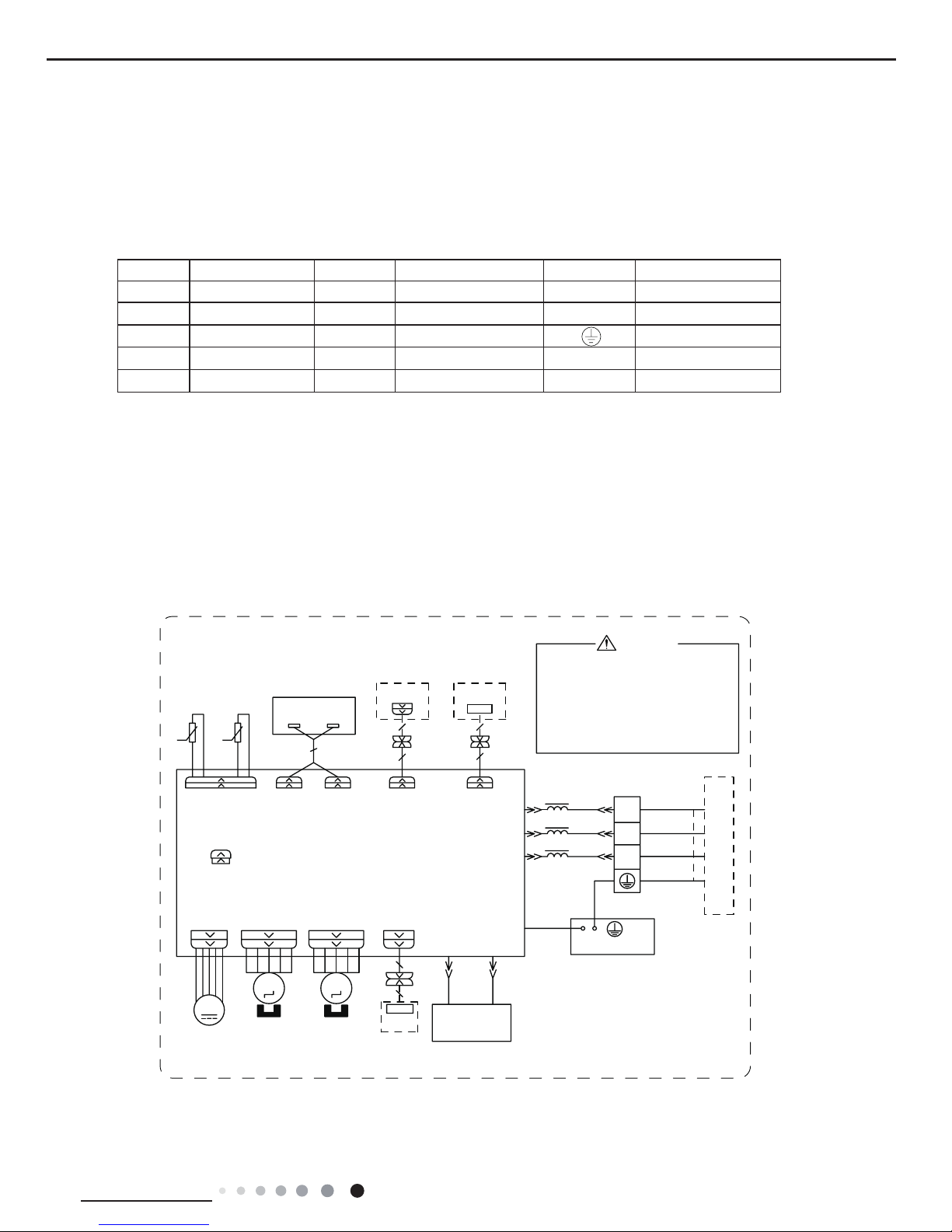
5.1 Wiring Diagram
● Indoor Unit
● Instruction
Symbol Symbol Color Symbol Symbol Color Symbol Name
WH White GN Green CAP Jumper cap
YE Yellow BN Brown COMP Compressor
RD Red BU Blue Grounding wire
YEGN Yellow/Green BK Black / /
VT Violet OG Orange / /
Note: Jumper cap is used to determine fan speed and the swing angle of horizontal lover for this model.
60000700033807
3OHDVHGRQWWRXFKDQ\
HOHFWURQLFFRPSRQHQWRU
WHUPLQDOZKHQWKHPDFKLQH
LVUXQQLQJVWRSSLQJRUKDV
EHHQSRZHUHGRIIIRUOHVV
WKDQPLQXWHVWRSUHYHQW
HOHFWULFVKRFN
287'22581,7
%8
%.
%1
<(*1
%/2&.
52207(03
78%(7(03
6(1625
6(1625
',63/$<%2$5'
5(&(,9(5$1'
0$,1%2$5'
-803
&$3
$3
6:,1*8'
76(1625
$&/
$3
',63',63
0
3(
(9$325$725
%.
1
<(*1
&20287
1
%1
%8
;7
7575
/
7(50,1$/
6:,1*/5
0
02725
67(33,1*
02725
67(33,1*
/()75,*+7
83'2:1
&2/'3/$60$
*(1(5$725
%85'
$3
:,),02'8/(
237,21$/
:,),&200$18$/
&211(&725
$3
:,5('
&21752//(5
0
)$102725
'&02725
237,21$/
3(
<(*1
&211(&725
/
/
&11(&7,1*
&$%/(
$3
'5<&
'225&
237,21$/
'5<&217$&7
:$51,1*
+($/7+/ +($/7+1
10
Service Manual
Technical Information
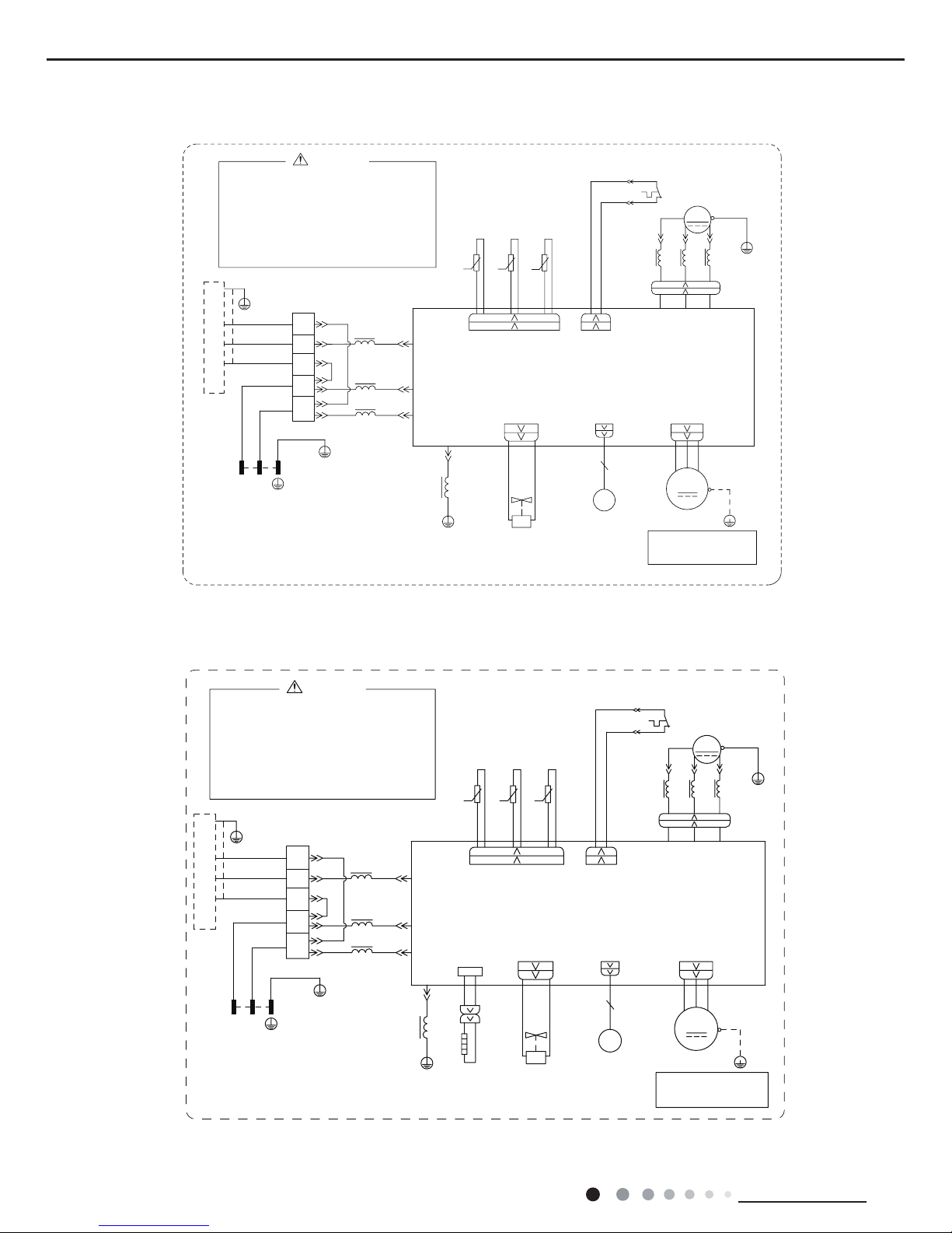
● Outdoor Unit
600007000339
60000700033902
These circuit diagrams are subject to change without notice, please refer to the one supplied with the unit.
1
/
<(*1
%8
3(
1
/
1
%1
%.
%8
;7
,1'22581,7
5,1*
%1
%8
%/2&.
7(50,1$/
0$*1(7,&
32:(5
%1%.
76(1625
&203
/
:
9
8
35,17('&,5&8,7%2$5'
3(
<(*1
)$102725
:$< 2)$1)$
7979
9$/9(
<9
:$<
0
3(
(.9
(OHFWURQLF
([SDQVLRQ
9DOYH
3(
<(*1
3(
5,1*
0$*1(7,&
29(5/2$'3527(&725
<(*1
:5'9<(8%8
8%(<
5'
3(
3(
57 57 57
5'
29&&203
+:+:
6$7
&203
;
8%(<
:+ %.
7(036(1625
28778%(
2875220
7(036(1625
(;+$867
7(036(1625
$3
...
<(*1
3(
/
/
%8
%1
%.
/
5,1*
0$*1(7,&
/ /
/
LURQVKHOOPRWRU
RQO\DSSOLHVWRWKH
127(0RWRUJURXQG
3OHDVHGRQWWRXFKDQ\
HOHFWURQLFFRPSRQHQWRU
WHUPLQDOZKHQWKHPDFKLQHLV
UXQQLQJVWRSSLQJRUKDV
EHHQSRZHUHGRIIIRUOHVV
WKDQPLQXWHVWRSUHYHQW
WKHULVNRIHOHFWULFVKRFN
:$51,1*
&20,11(5
1
$&B/
GWH24YE-K6DNA1A/O(CB437W01401)
GWH24YE-K6DNA1A/O(CB437W01400)
3OHDVHGRQWWRXFKDQ\
HOHFWURQLFFRPSRQHQWRU
WHUPLQDOZKHQWKHPDFKLQHLV
UXQQLQJVWRSSLQJRUKDV
EHHQSRZHUHGRIIIRUOHVV
WKDQPLQXWHVWRSUHYHQW
WKHULVNRIHOHFWULFVKRFN
:$51,1*
&20,11(5
1
$&B/
1
/
<(*1
%8
3(
1
/
1
%1
%.
%8
;7
,1'22581,7
5,1*
%1
%8
%/2&.
7(50,1$/
0$*1(7,&
32:(5
%1%.
76(1625
&203
/
:
9
8
35,17('&,5&8,7%2$5'
3(
<(*1
)$102725
:$< 2)$1)$
7979
9$/9(
<9
:$<
0
3(
(.9
(OHFWURQLF
([SDQVLRQ
9DOYH
3(
<(*1
3(
5,1*
0$*1(7,&
29(5/2$'3527(&725
<(*1
:5'9<(8%8
8%(<
5'
3(
3(
57 57 57
5'
29&&203
+:+:
6$7
&203
;
8%(<
:+ %.
7(036(1625
28778%(
2875220
7(036(1625
(;+$867
7(036(1625
$3
...
<(*1
3(
/
/
%8
%1
%.
/
5,1*
0$*1(7,&
/ /
/
LURQVKHOOPRWRU
RQO\DSSOLHVWRWKH
127(0RWRUJURXQG
+($7%
(+
5'
%27720
+($7(5
%$1'
5'
11
Service Manual
Technical Information
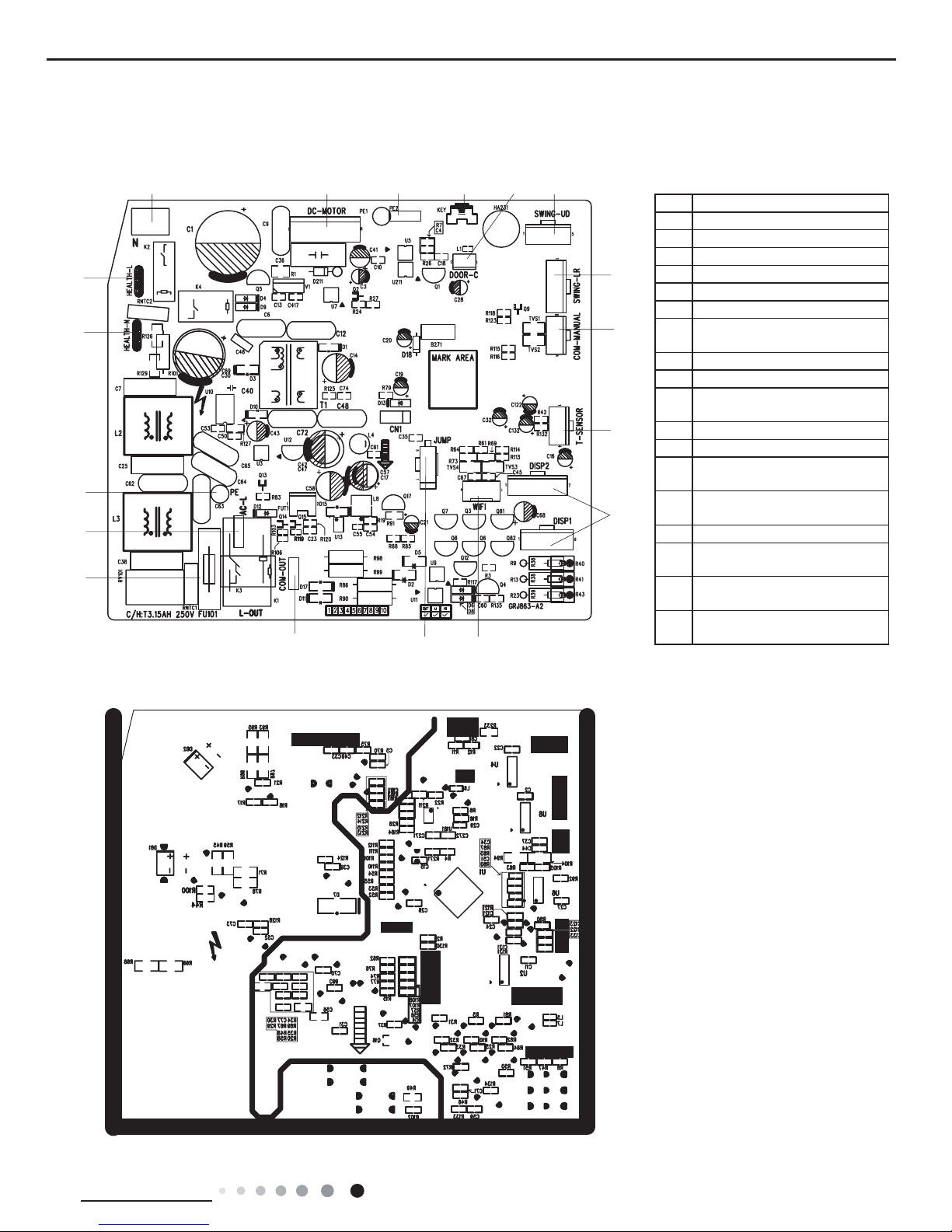
5.2 PCB Printed Diagram
Indoor Unit
● Top view
● Bottom view
1216 18
17
34
5
6
7
8
91
5
11
12
10
13
14
No. Name
1 Neutral wire
2 Needle stand for indoor fan
3 Auto button
4 Up&down swing motor
5 left&right swing motor
6 Interface of temperature sensor
7
Terminal for display board
connection
8 Terminal of jumper cap
9 Communication wire
10
Connect earthing wire(only for
the mode with this function)
11 Fuse
12 Live wire interface
13
Interface of health function
neutral wire
14
Interface of health function live
wire
15 Detecting plate(WIFI )
16
Connect earthing wire(only for
the mode with this function)
17
Wired controller (only for the
mode with this function)
18
Interface of gate control (only
for the mode with this function)

12
Service Manual
Technical Information
Outdoor Unit
Top View
Bottom View
NO. Name NO. Name NO. Name
1 Compressor three phase input interface 6Terminal of high pressure protection 11 Te rminal of chassis electric heating
2
Terminal of low ambient temperature
cooling temperature sensor
7Terminal of low pressure protection 12 Terminal of live wire
3Terminal of electronic expansion valve 8Terminal of outdoor fan13Terminal of communication
4Terminal of outdoor temperature sensor 9Terminal of compressor electric heating 14 Terminal of grounding wire
5
Terminal of compressor overload
protection
10 Terminal of 4-way valve15Terminal of neutral wire
1
23 4567 8910
11
12
13
14
15

13
Service Manual
Technical Information
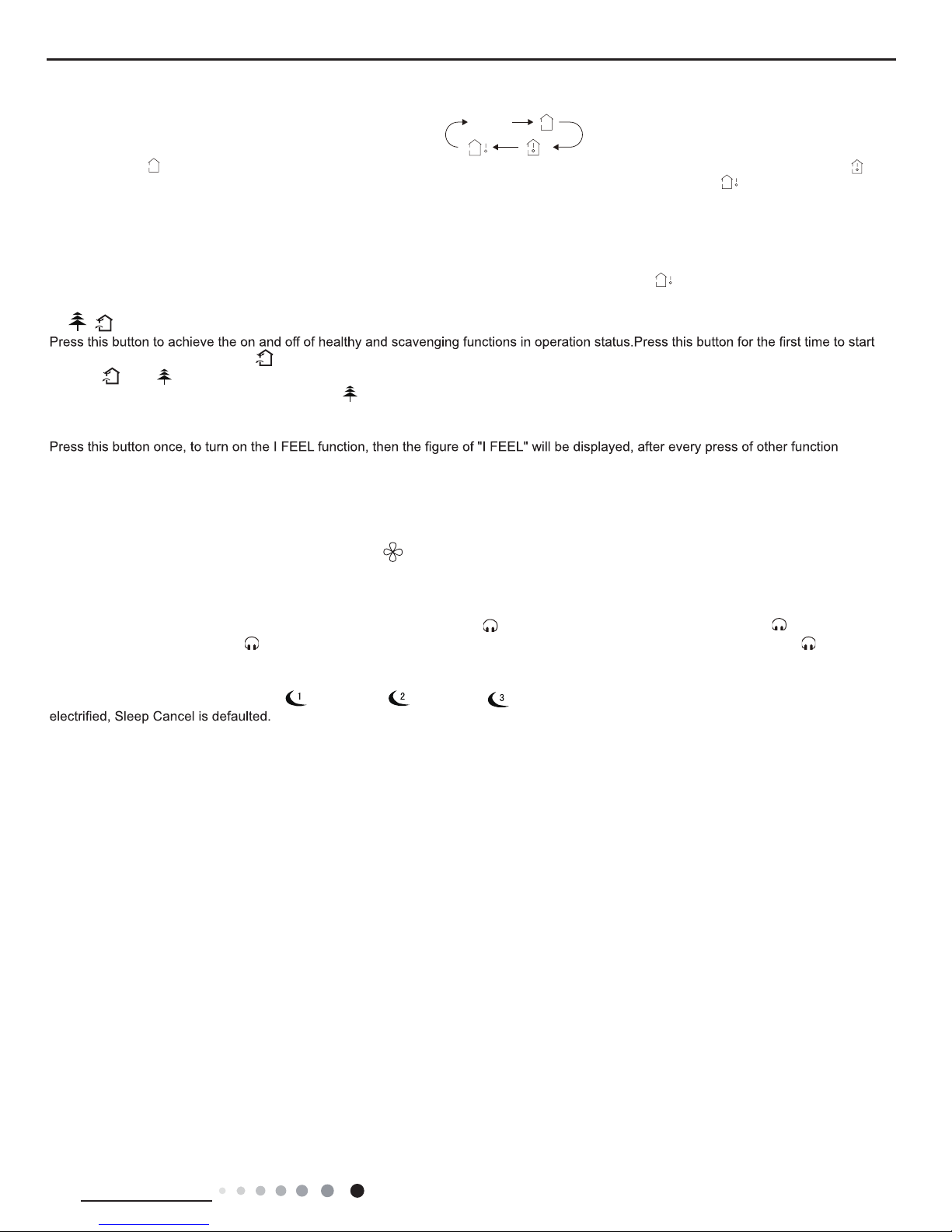
Buttons on Remote Controller
Introduction
for Icons on Display Screen
Introduction for Buttons on Remote Controller
Note:
●
After putting through the power, the air conditioner will give out a sound.Operation indic
●
This is a general use remote controller, it could be used for the air conditioners with multifunction; For some function, which the model
don't have, if press the corresponding button on the remote controller that the unit will keep the original running status
.
ator " " is ON (red indicator). A
fter that, you can
operate the air conditioner by using remote controlle
r.
● Under on status, pressing the button on the remote controller
, the signal icon " " on the display of remote controller will blink once and
the air conditioner will give out a “de” sound, which means the signal has been sent to the air conditioner
.
● Under of
f status, set temperature and clock icon will be displayed on the display of remote controller (If timer on, timer off and light
functions are set, the corresponding icons will be displayed on the display of remote controller at the same time); Under on st
atus, the
display will show the corresponding set function icons.
1. ON/OFF button
Press this button, the unit will be turned on, press it once more, the unit will be turned off. Sleep function will be canceled, while unit off.
1
2
3
4
5
6
7
8
9
10
11
12
button
button
X-FAN button
QUIET button
SLEEP button
TEMP button
I FEEL button
13
14
15
16
TURBO button
LIGHT button
button
TIMER ON/
TIMER OFF button
CLOCK button
1
2
3
4
ON/OFF button
FAN button
+/- button
MODE button
ON/OFF button
FAN button
+/- button
MODE button
3
4
2
1
(before opening cover (after opening cover
/
15
5
2
6
3
12
16
4
11
8
9
13
7
1
10
14
Send signal
Turbo mode
8ć heating function
Set temperature
Set time
X-FAN function
TIMER ON /TIMER OFF
Child lock
Up & down swing
Left & right swing
Set fan speed
Light
Temp. display type
: Set temp.
: Outdoor ambient temp.
: Indoor ambient temp.
Sleep mode
Clock
Heat mode
Fan mode
Dry mode
Cool mode
Auto mode
Operation mode
I feel
Healthy mode
Scavenging functions
Quiet
This is a general remote controller. Some
models have this function while some do
not. Please refer to the actual models.
6. Function and Control
6.1 Remote Controller Introduction
14
Service Manual
Technical Information
2. FAN button
Press this button,
Auto, Low, Medium-low, Medium, Medium-high, High speed can be circularly selected. After powered on, Auto fan speed
is default. Under DR
Y mode, Low fan speed only can be set up.
3. MODE button
Press this button,
Auto, Cool, Dry, Fan, Heat mode can be selected circularly. Auto mode is default while power on. Under Auto mode, the
temperature will not be displayed;Under Heat mode, the initial value is 28°C( 82°F);Under other modes, the initial value is 25°
C(77°F).
4. +/- button
● Presetting temperature can be increased.
Press this button,the temperature can be set up, continuously press this button and hold for two seconds, the relative content
s can quickly
change,until unhold this button and send the order that the °C(°F) signal will be displayed all the time.The temperature adjus
tment is
unavilable under the
Auto mode, but the order can be sent by if pressing this button.Temperature of Celsius degree setting:16-30;for
Fahrenheit degree setting:61-86.
● Presetting temperature can be decreased.
Press this button, the temperature can be set up, continuously press this button and hold for two seconds, the relative content
s can quickly
change,until unhold this button and send the order that the °C(°F) signal will be displayed all the time.The temperature adjus
tment is
unavailable under the
Auto mode,but the order can be sent by if pressing this button.
5. TURBO button
Under Cool or Heat mode,press this button can turn on or turn of
f the Turbo function.After the Turbo function turned on, the signal of Turbo
will displa
y. The signal will be automatically cancelled if changing the mode or fan speed.
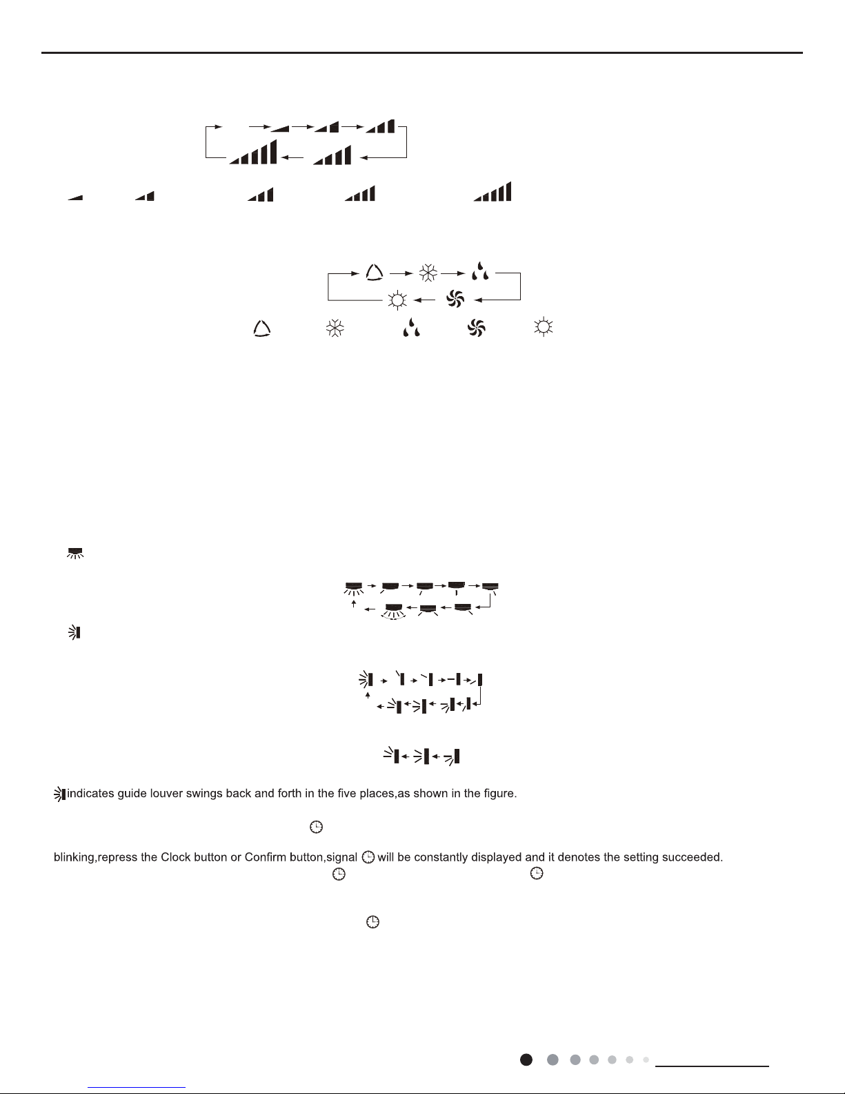
6. button
(This function is only available for some models)
Press this button to set left & right swing angle cycling as below:
7. button
Press this button to set swing angle,which circularly changes as below
:
This remote controller is universal. If it receives threes kinds of following status,the swing angle will remain origial.
If guide louver is stopped when it is swinging up and down,it will remain its present position.
8. CLOCK button
Press this button, the clock can be set up,signal blink and display
.Within 5 seconds, the value can be adjusted by pressing + or - button,
if continuously press this button for 2 seconds above,in every 0.5 seconds, the value on ten place of Minute will be increased
1.During
After
powered on, 12:00 is defaulted to display and signal will be displayed. If there is signal be displayed that denotes
the current time
value is Clock value, otherwise is
Timer value.
9. TIMER ON/TIMER OFF button
●
Timer On setting: Signal “ON”will blink and display,signal will conceal,the numerical section will become the timer on setting status.
During 5 seconds blink,by pressing + or - button to adjust the time value of numerical section,every press of that button,the
value will be
increased or decreased 1 minute.Hold pressing + or - button,2 seconds later
,it quickly change,the way of change is: During the initial 2.5
seconds,ten numbers change in the one place of minute,then the one place is constant,ten numbers change in the ten splace of m
inute at
2.5 seconds speed and carry
. During 5s blink,press the Timer button,the timer setting succeeds.The Timer On has been set up,repress the
timer button,theT
imer On will be canceled. Before setting theTimer,please adjust the Clock to the current actual time.
● One press this key to enter into TIMER OFF setup, in which case the TIMER OFF icon will blink. The method of setting is the sameas for
Note: It’s Low fan speed
under Dry mode.
(only for cooling and heating unit.
As for cooling only unit, it won’t
have any action when it receives
the signal of heating operation.)
Medium fanLow fan High fan
Medium-low fan Medium-high fan
ATUO
AUTO COOL DRYFAN HEAT
OFF
OFF
15
Service Manual
Technical Information
10. TEMP button
1
1. / button(This function is only available for some models)
scavenging function;LCD displays“ ”.Press the button for the second time to start healthy and scavenging functions simultan
eously;LCD
displays“ ”and “ ” .Press this button for the third time to quit healthy and scavenging functions simultaneously
.Press the button for the
fourth time to start healthy function; LCD display“ ” .Press this button again to repeat the operation above
.
NOTE: This function is applicable to partial of models.
12. I FEE
L button
button, every 200ms to send I FEE
L once, after this function started,the remote control will send temperature to the main un it in every 10
minutes.When repress this button, this function will be turned of
f.
13. LIGHT button
Press this button at unit On or Of
f status,Light On and Light Off can be set up.After powered on, Light On is defaulted.
14. X-F
AN button
Pressing X-F
AN button in COOL or DRY mode,the icon is displayed and the indoor fan will continue operation for 2 minutes in order
to dry the indoor unit even though you have turned of
f the unit.After energization, X-FAN OFF is defaulted.X-FAN is not available in
A
UTO,FAN or HEAT mode.
15. QUIET button
Press this button,the Quiet status is under the
Auto Quiet mode (display" " and “Auto”signal ) and Quiet mode(display " " singal) and
Quiet OFF(there is no signal of " " displayed),after powered on,the Quiet OFF is defaulted. Under the Quiet mode (Display
" "signal),
the fan speed is not available.
16. SLEE
P button
●Press this button, can select Sleep 1 ( ), Sleep 2 ( ),Sleep 3 ( ) and cancel the Sleep, circulate be
tween these, after
●Sleep 1 is Sleep mode 1, in Cool, Dehumidify modes: sleep status after run for one hour
, the main unit setting temperature will increase 1°C
(
1
°F or 2 °F
), 2 hours,setting temperature increased 2°C(3
°F or 4 °F
), the unit will run at this setting temperature; In Heat mode: sleep ,
status after run for one hour the setting temperature will decrease 1°C
(1
°F or 2 °F
), 2 hours, setting temperature will decrease 2°C, then
the unit will run at this setting temperature.
●Sleep 2 is sleep mode 2, that is air conditioner will run according to the presetting a group of sleep temperature curve.
In Cool mode:
(1) When setting the initial temperature 16~23°C
(61
°F or 74°F)
, after turned on Sleep function, the temperature will be increased 1°C
(
1
°F or 2 °F
) in every hour,after 3°C (5
°F or 6°F
)the temperature will be maintained, after 7hours,the temperature will be decreased 1°C,
after that the unit will keep on running under this temperature;
(2) When setting the initial temperature 24~27°C, after turned on Sleep function, the temperature will be increased 1°C in ever
y hour,after
2°C the temperature will be maintained, after 7hours,the temperature will be decreased 1°
C(1
°F or 2°F
), after that the unit will keep on runnin
g
under this temperature;
(3) When setting the initial temperature 28~29°C
(82
°F or 75°F
), after turned on Sleep function, the temperature will be increased 1°C
(
1
°F or 2 °F
) in every hour, after 1°C (1
°F or 2 °F
)the temperature will be maintained, after 7hours,the temperature will be decreased 1°C
(
1
°F or 2 °F
), after that the unit will keep on running under this temperature;
(4) When setting the initial temperature 30°C
(86°F), under this temperature setting, after 7hours, the temperature will be decreased 1°C
(
1
°F or 2 °F
), after that the unit will keep on running under this temperature;
In Heat mode:
(1) Under the initial presetting temperature 16°C
(61°F), it will run under this setting temperature all along.
(2) Under the initial presetting temperature17~20°C
(62
°F or 68°F)
, after Sleep function started up, the temperature will decrease 1°C
(
1
°F or 2 °F
)in every hour, after 1°C(1
°F or 2 °F
) decreased, this temperature will be maintained.
(3) Under the initial presetting temperature 21~27°C
(69
°F or 81°F)
, after Sleep function started up, the temperature will decrease 1°C
(
1
°F or 2 °F
) in every hour, after 2°C(3
°F or 4°F
) decreased, this temperature will be maintained.
(4) Under the initial presetting temperature 28~30°C
(82
°F or 86°F)
, after Sleep function started up, the temperature will decrease 1°C
3°C
(5
°F or 6°F
) decreased, this temperature will be maintained
Press this button, you can see indoor set temperature,indoor ambient temperature or outdoor ambient temperature on indoor unit’s display.
The setting on remote controller is selected circularly as below:
When selecting“ ”with remote controller or no display, temperature indicator on indoor unit displays set temperature; When
selecting“ ”
with remote controller,temperature indicator on indoor unit displays indoor ambient temperature; When selecting“ ”with remo
te controller,
temperature indicator on indoor unit displays outdoor ambient temperature. 3s later it will return to the setting temprature or
it depends on
the other received signal within 3s.
A
ttention: When displaying the outdoor ambient, the displaying range is 32-99 °F and 0-60°C,When it goes beyond the range, it keeps the
threshold data (the smallest 0 or 32°F and the largest 99°F or 60°C).
Warm tips: When operating buttons on the cover please make sure the cover is closed completely
.
NOTE: Outdoor temperature display is not available for some models. At that time, indoor unit receives“ ”signal, while it di
splays indoor set
temperature.
no display
16
Service Manual
Technical Information
the place of setting temperature "88" will display the corresponding temperature of last setting sleep curve and blink
;
control will resume the original timer display;temperature display will resume to original setting temperature.
●Sleep3- the sleep curve setting under Sleep mode by DI
Y could be inquired:
The user could accord to sleep curve setting method to inquire the presetting sleep curve, enter into user individuation sleep
setting status,
Note: In the above presetting or enquiry procedure, if continuously within10s, there is no button pressed, the sleep curve sett
ing status will
be automatically quit and resume to display the original displaying. In the presetting or enquiry procedure, press "ON/OFF" but
ton, "Mode"
button, "T
imer" button or "Sleep" button, the sleep curve setting or enquiry status will quit similarly.
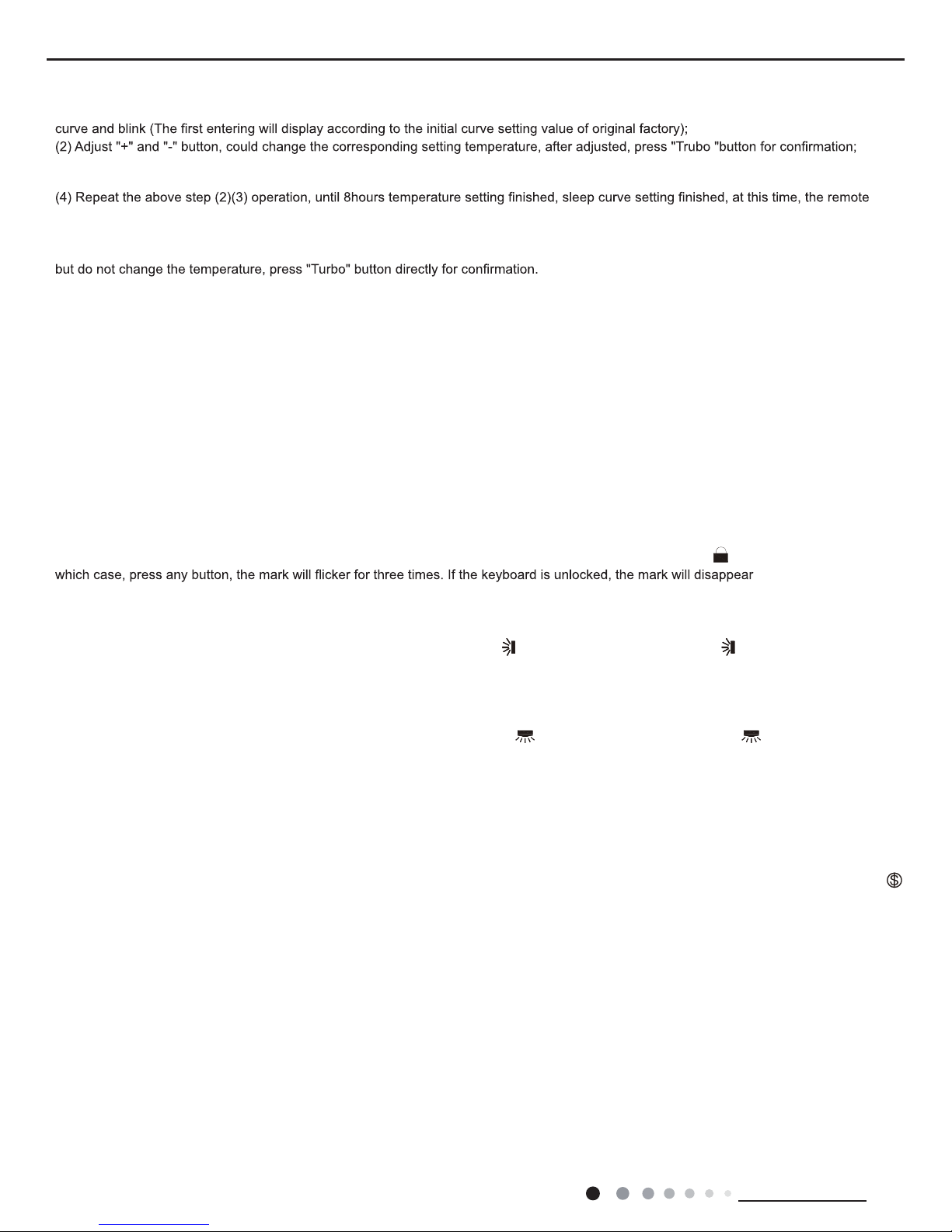
17.
About X-FAN function
This function indicates that moisture on evaporator of indoor unit will be blowed after the unit is stopped to avoid mould.
(1)Having set X-F
AN function on: After turning off the unit by pressing ON/OFF button indoor fan will continue running for about 2 min. at
low speed. In this period, press X-F
AN button to stop indoor fan directly.
(2)Having set X-F
AN function off: After turning off the unit by pressing ON/OFF button, the complete unit will be off directly.
18.
About AUTO RUN
When
AUTO RUN mode is selected, the setting temperature will not be displayed on the LCD, the unit will be in accordance with the room
temp. automatically to select the suitable running method and to make ambient comfortable.
19.
About turbo function
If start this function, the unit will run at super-high fan speed to cool or heat quickly so that the ambient temp. approachs
the preset temp.
as soon as possible.
20.
About lock
Press + and - buttons simultaneously to lock or unlock the keyboard. If the remote controlleris locked, the icon will be
displayed on it, in
.
21.
About swing up and down
(1)Press swing up and down button continuously more than 2s,the main unit will swing back and forth from up to down, and then
loosen
the button, the unit will stop swinging and present position of guide louver will be kept immediately
.
(2)Under swing up and down mode, when the status is switched from of
f to , if press this button again 2s later, status will switch to off
status directly; if press this button again within 2s,the change of swing status will also depend on the circulation sequence
stated above.
22.
About swing left and right(This function is only available for some models)
(1)Press swing left and right button continuously more than 2s,the main unit will swing back and forth from left to right, and
then loosen the
button, the unit will stop swinging and present position of guide louver will be kept immediately
.
(2)2. Under swing left and right mode, when the status is switched from of
f to , if press this button again 2s later, status will switch to
of
f status directly; if press this button again within 2s,the change of swing status will also depend on the circulation sequence stated above.
23.
About switch between Fahrenheit and Centigrade
Under status of unit of
f, press MODE and - buttons simultaneously to switch °C and °F.
24. Combination of " TEMP" and "CLOCK" buttons :
About Energy-saving Function
Press “TEMP” and “CLOCK” simultaneously in COOL
mode to start energy-saving function.Nixie tube on the remote controller displays “SE”.
Repeat the operation to quit the function.
25. Combination of " TEMP" and "CLOCK" buttons :
About 8°C(46°F) Heating Function(This function is only available for some models)
Press “TEMP” and “CLOCK” simultaneously in HE
AT mode to start 8°C(46°F)Heating Function.Nixie tube on the remote controller displays"
"and a selected temperature of “8°C” (46°F if Fahrenheit is adopted). Repeat the operation to quit the function.
26.
About Auto Quiet function
When auto quiet function is selected:
(1)Under cooling mode: indoor fan operates at notch 4 speed. 10 minutes later or when indoor ambient temperature≤28°C(82°F), in
door fan
will operate at notch 2 speed or quiet mode according to the comparison between indoor ambinet temperature and set temperatur
e.
(2)Under heating mode: indoor fan operates at notch 3 speed or quiet mode according to the comparison between indoor ambient
temperature and set temperature.
(3)Under dr
y, fan mode: indoor fan operates at quiet mode.
(4)Under auto mode: the indoor fan operates at the auto quiet mode according to actual cooling, heating or fan mode.
27.
About Sleep function
28.
WIFI Fuction (This unit is without WiFi fuction)
Under the Fan and
Auto mode, the Sleep function cannot be set up, under Dehumidify mode, only Sleep 1 can be selected.Select and
enter into any kind of Sleep mode, the Quiet function will be attached and stared, dif
Press "MODE" and "TURBO" button simultaneously to turn on or turn off WIFI function. When WIFI function is turned on, the " Wi
Fi" icon will
be displayed on remote controller; Long press "MODE" and "TURBO" buttons simultaneously for 10s, remote controller will send WIFI reset
ferent Quiet status could be optional and turned off.
(3)
At this time, 1hour will be automatically increased at the timer postion on the remote control, (that are "2hours" or "3hours" or "8hours "),
●Sleep 3- the sleep curve setting under Sleep mode by DIY:
(1) Under Sleep 3 mode, press "T
urbo" button for a long time, remote control enters into user individuation sleep setting status, at this time,
the time of remote control will display "1hour ", the setting temperature "88" will display the corresponding temperature of la
st setting sleep
17
Service Manual
Technical Information
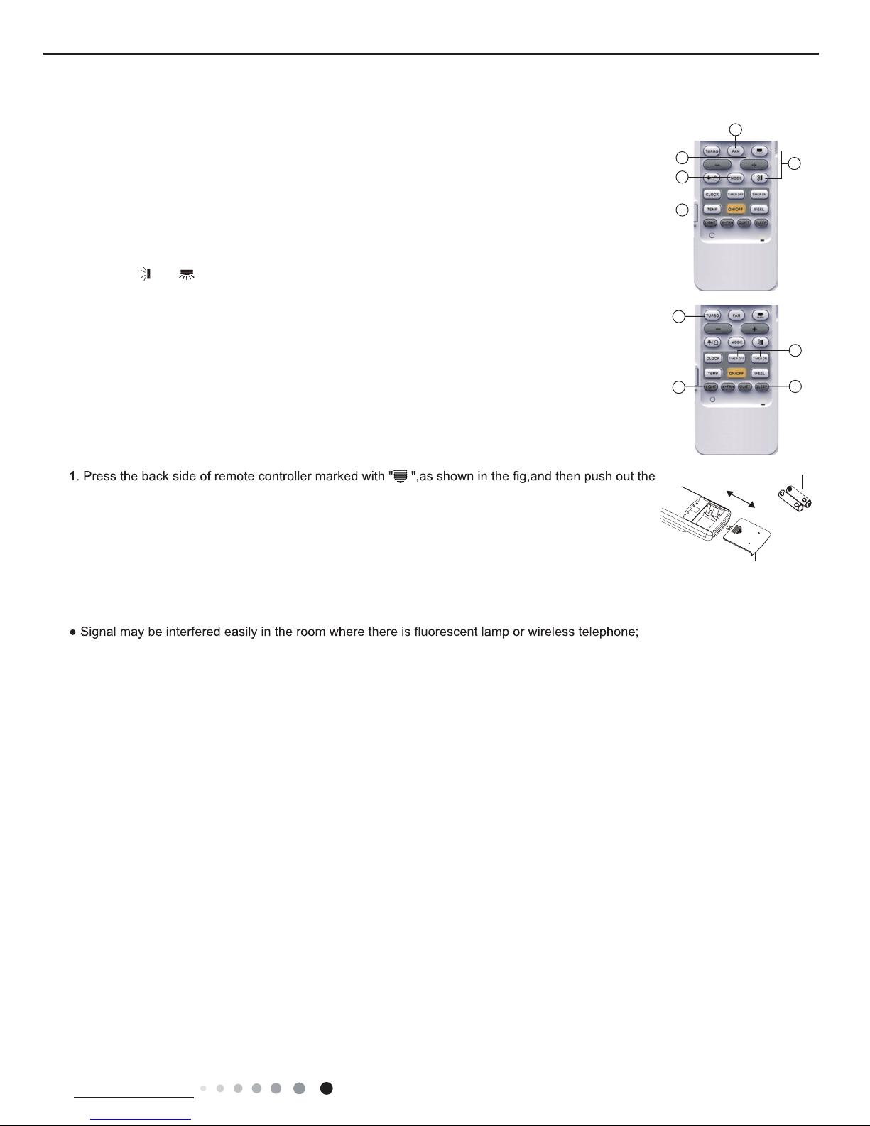
Operation Guide
Replacement of Batteries in Remote Controller
1. General operation
(1)After powered on, press ON/OFF button, the unit will start to run. (Note: When it is powered on, the
guide louver of main unit will close automaticall
y.)
(2)Press MODE button, select desired running mode.
(3)Pressing + or - button, to set the desired temperature (It is unnecessary to set the temp. at
AUTO
mode.)
(4)Pressing F
AN button, set fan speed, can select AUTO FAN,LOW, MEDIUM-LOW, MEDIUM, MEDIUM-
HIGH and HIGH.
2. Optional operation
(1)Press SLEE
P button, to set sleep.
(2)Press
TIMER ON and TIMER OFF button, can set the scheduled timer on or timer off.
(3)Press LIGH
T button, to control the on and off of the displaying part of the unit (This function may be not
available for some units).
(4)Press
TURBO button, can realize the ON and OFF of TURBO function.
cover of battery box along the arrow direction.
2. Replace two 7# (AAA 1.5V) dry batteries, and make sure the position of "+" polar and "-" polar are
correct.
3. Reinstall the cover of battery box.
Note:
● During operation, point the remote control signal sender at the receiving window on indoor unit.
● The distance between signal sender and receiving window should be no more than 8m, and there
should be no obstacles between them.
remote controller should be close to indoor unit during operation.
● Replace new batteries of the same model when replacement is required.
● When you don’t use remote controller for a long time, please take out the batteries.
● If the display on remote controller is fuzzy or there’s no display, please replace batteries.
5
1
2
3
4
(5)
Pressing and button, to select the swing.
battery
Cover of battery box
remove
reinstall
1
2
3
4
18
Service Manual
Technical Information
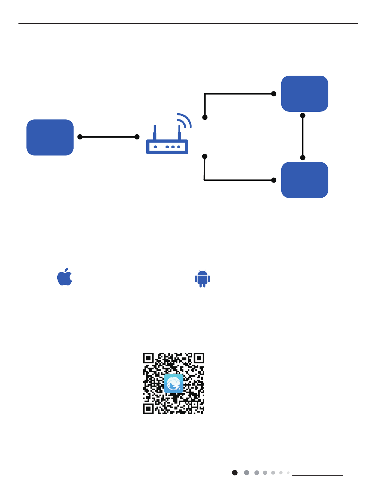
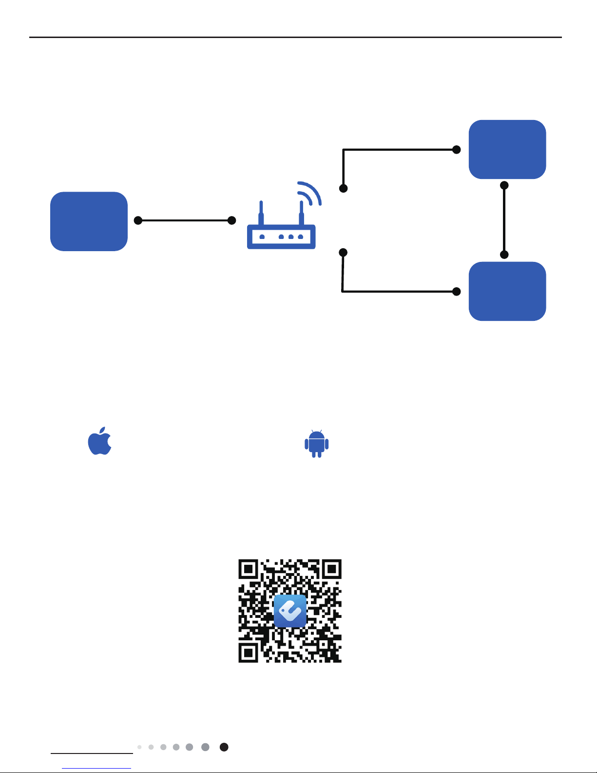
6.2 GREE+ App Operation Manual
Control Flow Chart
Download and installation
Operating Systems
Requirement for User's smart phone:
Scan the QR code or search "GREE+" in the application market to download and install it. When "GREE+" App is installed, register the
account and add the device to achieve long-distance control and LAN control of Gree smart home appliances.
For more information, please refer to "Help" in App.
Internet
Cellular/
Other Wi-FI
Home Wi-Fi
Home wireless router
Home Wi-Fi
Gree
Gree Cloud
GREE+ APP
intelligent
home
appliances
iOS system
Support iOS7.0 and
above version
Android system
Support Android 4.4
and
above version
GREE+ App Download Linkage
19
Service Manual
Technical Information
Control Flow Chart
Download and installation
Operating Systems
Requirement for User's smart phone:
Scan the QR code or search "Ewpe Smart" in the application market to download and install it. When "Ewpe Smart" App is installed,
register the account and add the device to achieve long-distance control and LAN control of smart home appliances.
For more information, please refer to "Help" in App.
6.3 Ewpe Smart App Operation Manual
iOS system
Support iOS7.0 and
above version
Android system
Support Android 4.4
and
above version
App Download Linkage
Internet
Cellular/
Other Wi-FI
Home Wi-Fi
Home wireless router
Home Wi-Fi
Cloud
APP
intelligent
home
appliances

20
Service Manual
Technical Information
6.4 Brief Description of Modes and Functions
1. Basic function of system
(1) Cooling mode
(1) Under this mode, fan and swing operates at setting status. Temperature setting range is 16~30OC.
(2) During malfunction of outdoor unit or the unit is stopped because of protection, indoor unit keeps original operation status.
(2) Drying mode
(1) Under this mode, fan operates at low speed and swing operates at setting status. Temperature setting range is 16~30OC.
(2) During malfunction of outdoor unit or the unit is stopped because of protection, indoor unit keeps original operation status.
(3) Protection status is same as that under cooling mode.
(4) Sleep function is not available for drying mode.
(3) Heating mode
(1) Under this mode, Temperature setting range is 16~30OC.
(2) Working condition and process for heating mode:
When turn on the unit under heating mode, indoor unit enters into cold air prevention status. When the unit is stopped or at OFF status,
and indoor unit has been started up just now, the unit enters into residual heat-blowing status.
(4) Working method for AUTO mode:
1.Working condition and process for AUTO mode:
a.Under AUTO mode, standard heating Tpreset=20OC and standard cooling Tpreset=25OC. The unit will switch mode automatically
according to ambient temperature.
2.Protection function
a. During cooling operation, protection function is same as that under cooling mode.
b. During heating operation, protection function is same as that under heating mode.
3. Display: Set temperature is the set value under each condition. Ambient temperature is (Tamb.-Tcompensation) for heat pump unit
and Tamb. for cooling only unit.
4. If there’s I feel function, Tcompensation is 0. Others are same as above.
(5) Fan mode
Under this mode, indoor fan operates at set fan speed. Compressor, outdoor fan, 4-way valve and electric heating tube stop operation.
Indoor fan can select to operate at high, medium, low or auto fan speed. Temperature setting range is 16~30OC.
2. Other control
(1) Buzzer
Upon energization or availably operating the unit or remote controller, the buzzer will give out a beep.
(2) Auto button
If press this auto button when turning off the unit, the complete unit will operate at auto mode. Indoor fan operates at auto fan speed
and swing function is turned on. Press this auto button at ON status to turn off the unit.
(3) Auto fan
Heating mode: During auto heating mode or normal heating ode, auto fan speed will adjust the fan speed automatically according to
ambient temperature and set temperature.
(4) Sleep
After setting sleep function for a period of time, system will adjust set temperature automatically.
(5) Timer function:
General timer and clock timer functions are compatible by equipping remote controller with different functions.
(6) Memory function
memorize compensation temperature, off-peak energization value.
Memory content: mode, up&down swing, light, set temperature, set fan speed, general timer (clock timer can’t be memorized).
After power recovery, the unit will be turned on automatically according to memory content.
(7) Health function
During operation of indoor fan, set health function by remote controller. Turn off the unit will also turn off health function.
Turn on the unit by pressing auto button, and the health is defaulted ON.
●
Indoor Unit

21
Service Manual
Technical Information
(8) I feel control mode
After controller received I feel control signal and ambient temperature sent by remote controller, controller will work according to the ambient
temperature sent by remote controller.
(9) Compulsory defrosting function
(1) Start up compulsory defrosting function
Under ON status, set heating mode with remote controller and adjust the temperature to 16℃. Press “+, -, +, -, +,-” button successively
within 5s and the complete unit will enter into compulsory defrosting status. Meanwhile, heating indicator on indoor unit will ON 10s and OFF
0.5s successively. (Note: If complete unit has malfunction or stops operation due to protection, compulsory defrosting function can be started
up after malfunction or protection is resumed.
(2) Exit compulsory defrosting mode
After compulsory defrosting is started up, the complete unit will exit defrosting operation according to the actual defrosting result, and the
complete unit will resume normal heating operation.
(10) Refrigerant recovery function:
(1) Enter refrigerant recycling function
Within 5min after energizing (unit ON or OFF status is ok), continuously press LIGHT button for 3 times within 3s to enter refrigerant
recycling mode; Fo is displayed and refrigerant recycling function is started. At this moment, the maintenance people closes liquid valve.
After 5min, stick the thimble of maintenance valve with a tool. If there is no refrigerant spraying out, close the gas valve immediately and
then turn off the unit to remove the connection pipe.
(2) Exit refrigerant recycling function
After entering refrigerant recycling mode, when receive any remote control signal or enter refrigerant recycling mode for 25min, the unit will
exit refrigerant recycling mode automatically If the unit is in standby mode before refrigerant recycling, it will be still in standby mode after
nishing refrigerant recycling; if the unit is in ON status before refrigerant recycling, it will still run in original operation mode.
(11) Ambient temperature display control mode
1. When user set the remote controller to display set temperature (corresponding remote control code: 01), current set temperature will be
displayed.
2. Only when remote control signal is switched to indoor ambient temperature display status (corresponding remote control code: 10) from
other display status (corresponding remote control code: 00, 01,11),controller will display indoor ambient temperature for 3s and then turn
back to display set temperature.
Under this mode, indoor fan operates at set fan speed. Compressor, outdoor fan, 4-way valve and electric heating tube stop operation.
Indoor fan can select to operate at high, medium, low or auto fan speed. Temperature setting range is 16~30OC.
(12) Off-peak energization function:
Adjust compressor’s minimum stop time. The original minimum stop time is 180s and then we change to:
The time interval between two start-ups of compressor can’t be less than 180+T s(0≤T≤15). T is the variable of controller. That’s to say
the minimum stop time of compressor is 180s~195s. Read-in T into memory chip when refurbish the memory chip each time. After power
recovery, compressor can only be started up after 180+T s at least.
(13) SE control mode
The unit operates at SE status.
(14) X-fan mode
When X-fan function is turned on, after turn off the unit, indoor fan will still operate at low speed for 2min and then the complete unit will be
turned off. When x-fan function is turned off, after turn off the unit, the complete unit will be turned off directly.
(15) 8º heating function
Under heating mode, you can set 8º heating function by remote controller. The system will operate at 8ºset temperature.
(16) Turbo function
This function can be set in cooling or heating mode, but not in auto, drying or fan mode. Press fan button to cancel this function.

22
Service Manual
Technical Information
●
Outdoor Unit
1. Input Parameter Compensation and Calibration
(1) Check the ambient temperature compensation function Indoor ambient temperature compensation function.
a. In cooling mode, the indoor ambient temperature participating in computing control = (T
indoor ambient temperature
–⊿T
cooling indoor ambient temperature
compensation
)
b. In heating mode, the indoor ambient temperature participating in computing control= (T
indoor ambient temperature
–⊿T
heating indoor ambient temperature
compensation
)
(2) Check effective judgment controls of parameters
Effective judgment function of the outdoor exhaust temperature thermo-bulb When conditions a and b are satised, the outdoor exhaust
temperature thermo-bulb is judged not to be connected into place, the mainboard of outer units will display failure of the outdoor exhaust
temperature thermo-bulb (not connected into place), stop the machine for repairing, and resume the machine by remote controls of ON/
OFF.
a. Judgment of exhaust detection temperature change:
After the compressor starts up and runs for 10 minutes, if the compressor frequency f ≥ 40Hz, and the rising value Texhaust (T
exhaust (after start-
up for 10 minutes)
- T
exhaust (before start-up)
) < 2ºC , the outdoor exhaust temperature thermo-bulb can be judged not to be connected into place (judging
once when the power is on the rst time).
b. Comparative judgment of exhaust detection temperature and condenser detection temperature (T
pipe temperature
= T
outdoor pipe temperature in cooling
mode
, T
pipe temperature
= T
indoor pipe temperature in heating mode
): After the compressor starts up and runs for 10 minutes, if the compressor frequency f ≥
40Hz, and T
pipe temperature
≥(T
exhaust+3
), the outdoor exhaust temperature thermobulb can be judged not to be connected into place (judging
once when power is on the rst time).
2. Basic Functions
(1) Cooling Mode
1. Conditions and processes of cooling operation:
(1) If the compressor is shut down, and [Tsetup – (T
indoor ambient temperature
– ⊿T
cooling indoor ambient temperature compensation)
] ≤ 0.5 , start up the machine
for cooling, the cooling operation will start;
(2) During operations of cooling, if 0ºC ≤ [Tsetup – (T
indoor ambient temperature
– ⊿T
cooling indoor ambient temperature compensation)
] < 2 , the cooling operation
will be still running;
(3) During operations of cooling, if 2ºC ≤ [Tsetup – (T
indoor ambient temperature
– ⊿T
cooling indoor ambient temperature compensation)
], the cooling operation will
stop after reaching the temperature point.
2. Temperature setting range
(1) If T
outdoor ambient temperature
≥ [T
low-temperature cooling temperature
], the temperature can be set at: 16~30ºC (Cooling at room temperature);
(2) If T
outdoor ambient temperature
< [T
low-temperature cooling temperature
], the temperature can be set at: 25~30ºC (Cooling at low temperature), that is, the
minimum setting temperature for outer units judgment is 25ºC .
(2) Dehumidifying Mode
1. Conditions and processes of dehumidifying operations: Same as the cooling mode;
2. The temperature setting range is: 16~30ºC ;
(3) Air-supplying Mode
1. The compressor, outdoor fans and four-way valves are switched off;
2. The temperature setting range is: 16~30ºC.
(4) Heating Mode
1. Conditions and processes of heating operations: (Tindoor ambient temperature is the actual detection temperature of indoor environment
thermo-bulb, Theating indoor ambient temperature compensation is the indoor ambient temperature compensation during heating
operations)
(1) If the compressor is shut down, and [(T
indoor ambient temperature
– ⊿T
heating indoor ambient temperature compensation
) –T
setup
] ≤ 0.5 , start the machine to
enter into heating operations for heating;
(2) During operations of heating, if 0ºC ≤ [(T
indoor ambient temperature
–⊿ T
heating indoor ambient temperature compensation
) –T
setup
] < 2 , the heating operation
will be still running;
(3) During operations of heating, if 2ºC ≤ [(T
indoor ambient temperature
– ⊿T
heating indoor ambient temperature compensation
) –T
setup
], the heating operation will
stop after reaching the temperature point.
2. The temperature setting range in this mode is: 16~30ºC .

23
Service Manual
Technical Information
3. Special Functions
Defrosting Control
①
Conditions for starting defrosting
After the time for defrosting is judged to be satised, if the temperature for defrosting is satised after detections for continuous 3minutes,
the defrosting operation will start.
②
Conditions of nishing defrosting
The defrosting operation can exit when any of the conditions below is satised:
③
T
outdoor pipe temperature
≥ (T
outdoor ambient temperature
– [T
temperature 1 of nishing defrosting
];
④
The continuous running time of defrosting reaches [tmax. defrosting time].
4. Control Logic
(1) Compressor Control
Start the compressor after starting cooling, heating, dehumidifying operations, and the outer fans start for 5s; When the machine is
shutdown, in safety stops and when switching to air-supplying mode, the compressor will stop immediately. In all modes: once the
compressor starts up, it will not be allowed to stop until having run for the [tmin. compressor running time] (Note: including cases of
shutdown when the temperature point is reached; except the cases requiring stopping the compressor such as fault protection, remote
shutdown, mode switching etc.); In all modes: once the compressor stops, it will be allowed be restart after 3-minute delay (Note: The
indoor units have a function of power memory, the machine can be restarted after remote shutdown and powering up again without
delay).
1. Cooling mode
Start the machine to enter into cooling operation for cooling, the compressor is switched on.
2. Dehumidifying mode
Same as the cooling mode.
3. Air-supplying mode
The compressor is switched off.
4. Heating mode
(1) Start the machine to enter into heating operation for heating, the compressor is switched on.
(2) Defrosting:
a. Defrosting starts: the compressor is shut down, and restarts it after 55-second delay.
b. Defrosting ends: the compressor stops, then starts it after 55-second delay.
(2) Outer Fans Control
Notes:
Only the outer fans run for at least 80s in each air ow speed can the air ow be switched;
After the outer fans run compulsively in high speed for 80s when the machine starts up, control the air ow according to the logic.
After remote shutdown, safety stops, and when the machine stops after reaching the temperature point, as well as after the compressor
stops, extend 1 minute, the outer fans will stop (During the period in the 1 minute, the air ow of outer fans can be changed according to
the outdoor ambient temperature changes); When running with force, the outdoor fans shall run in the highest air ow.
(3) 4-way valve control
1. The 4-way valve control under the modes of Cooling, dehumidication and supplying air: closing;
2. The status of 4-way valve control under the heating mode: getting power;
(1) 4-way valve power control under heating mode
a. Starts the machine under heating mode, the 4-way valve will get power immediately.
(2) 4-way valve power turn-off control under heating mode
a. When you should turn off the power or switch to other mode under heating mode, the power of 4-way valve will be cut after 2 minutes
of the compressor stopped.
b. When all kinds of protection stops, the power of 4-way valve will be cut after delaying 4 minutes.
(3) Defrosting control under heating mode:
a. Defrosting begins: The power of 4-way valve will be cut after 50s of entering into the defrosting
compressor.
b. Defrosting stops: The 4-way valve will get power after 50s of exiting the defrosting compressor.
(4) Evaporator frozen-preventing protection function
At the mode of Cooling, dehumidifying:
Evaporator frozen-preventing protection function is allowed to begin after 6 min of starting the compressor.
 Loading...