

Gree GWH12QB-K3DNA5D, GWH12QB-K3DNE2D, GWH12QB-K3DNC4D, GWH18QD-K3DNA6O, GWH12QB-K3DNA6D Service Manual
...
GREE ELECTRIC APPLIANCES,INC.OF ZHUHAI
Change for Life
Service Manual
Models: GWH12QB-K3DNA5D(WIFI)
GWH12QB-K3DNC4D(WIFI)
GWH12QB-K3DNE2D(WIFI)
GWH12QB-K3DNA6D(WIFI)
GWH18QD-K3DNA5E(WIFI)
GWH18QD-K3DNA6E(WIFI)
GWH18QD-K3DNC4E(WIFI)
GWH18QD-K3DNE2E(WIFI)
(Refrigerant:R410A)

Service Manual
Table of Contents
Table of Contents
Part
Ⅰ
: Technical Information
.......................................................................1
1. Summary
......................................................................................................................1
2. Specications
..........................................................................................................2
2.1 Specication Sheet ...........................................................................................................2
2.2 Operation Characteristic Curve ........................................................................................4
2.3 Capacity Variation Ratio According to Temperature .........................................................4
2.4 Cooling and Heating Data Sheet in Rated Frequency .....................................................5
2.5 Noise Curve ......................................................................................................................5
3. Outline Dimension Diagram
........................................................................6
3.1 Indoor Unit ........................................................................................................................6
3.2 Outdoor Unit .....................................................................................................................7
4. Refrigerant System Diagram
......................................................................8
5. Electrical Part
...........................................................................................................9
5.1 Wiring Diagram .................................................................................................................9
5.2 PCB Printed Diagram .....................................................................................................12
6. Function and Control
......................................................................................14
6.1 Remote Controller Introduction .....................................................................................14
6.2 Operation of Smart Control (Smart Phone, Tablet PC) For Gree ...................................18
6.3 Operation of Smart Control (Smart Phone, Tablet PC) .................................................30
6.4 Brief Description of Modes and Functions ......................................................................42
Part
Ⅱ
: Installation and Maintenance
.................................................51
7. Notes for Installation and Maintenance
..........................................51
8. Installation
................................................................................................................53
8.1 Installation Dimension Diagram ......................................................................................53
8.2 Installation Parts-checking ............................................................................................55
8.3 Selection of Installation Location ....................................................................................55
8.4 Electric Connection Requirement ..................................................................................55
8.5 Installation of Indoor Unit ................................................................................................55
8.6 Installation of Outdoor Unit .............................................................................................58
8.7 Vacuum Pumping and Leak Detection ...........................................................................59
8.8 Check after Installation and Test Operation ...................................................................59

Service Manual
9. Maintenance
............................................................................................................60
9.1 Error Code List ...............................................................................................................60
9.2 Troubleshooting for Main Malfunction ............................................................................71
9.3 Troubleshooting for Normal Malfunction .........................................................................85
10. Exploded View and Parts List
..............................................................87
10.1 Indoor Unit ....................................................................................................................87
10.2 Outdoor Unit .................................................................................................................95
11. Removal Procedure
.......................................................................................97
11.1 Removal Procedure of Indoor Unit ...............................................................................97
11.2 Removal Procedure of Outdoor Unit ..........................................................................102
Appendix:
......................................................................................................................106
Appendix 1: Reference Sheet of Celsius and Fahrenheit ..................................................106
Appendix 2: Conguration of Connection Pipe ...................................................................106
Appendix 3: Pipe Expanding Method .................................................................................107
Appendix 4: List of Resistance for Temperature Sensor ....................................................108
1
Technical Information
Service Manual
1. Summary
Part
Ⅰ
: Technical Information
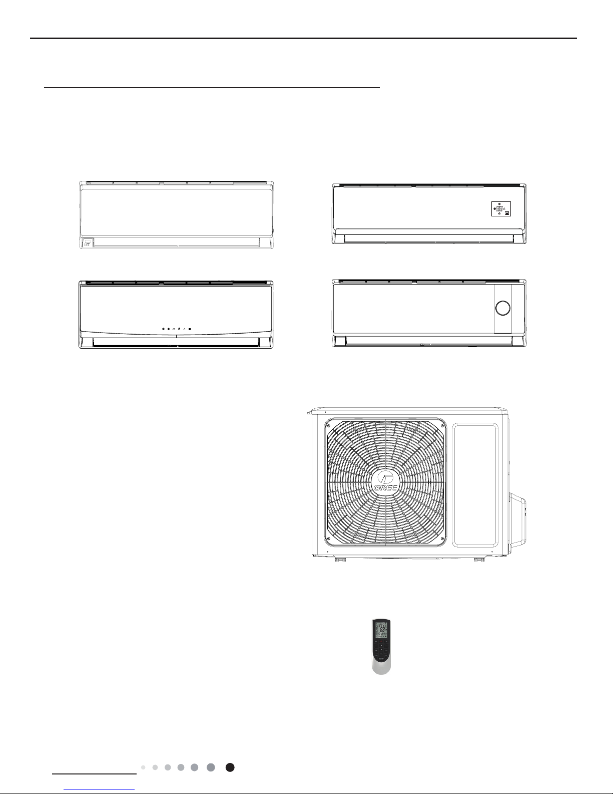
Indoor Unit
A6 Panel
A5 Panel
C2 Panel
E2 Panel
GWH12QB-K3DNA6D/O
GWH18QD-K3DNA6E/O
Outdoor Unit
Remote Controller
YAN1F1
2
Technical Information
Service Manual
2. Specications
2.1 Specication Sheet
Model
1.GWH12QB-K3DNA6D
2.GWH12QB-K3DNC4D
3.GWH12QB-K3DNE2D
4.GWH12QB-K3DNA5D
1.GWH18QD-K3DNA6E
2.GWH18QD-K3DNA5E
3.GWH18QD-K3DNC4E
4.GWH18QD-K3DNE2E
Product Code
1.CB427004702 CB427004703
2.CB444001502
3.CB462000201
4.CB425007001
1.CB427006400 CB427006401
2.CB425007100
3.CB444002900
4.CB462000300
Power
Supply
Rated Voltage V~ 220-240 220-240
Rated Frequency Hz 50 50
Phases 1 1
Power Supply Mode Outdoor Outdoor
Cooling Capacity(Min~Max) W 3200 4600
Heating Capacity(Min~Max) W 3400 5000
Cooling Power Input(Min~Max) W 997 1430
Heating Power Input(Min~Max) W 942 1380
Cooling Current Input A 4.50 6.34
Heating Current Input A 4.4 6.12
Rated Input W 1500 1860
Rated Current A 7.2 7.45
Air Flow Volume(SH/H/M/L/SL) m3/h 560/480/410/290/
-
850/720/610/520/
-
Dehumidifying Volume L/h 1.4 1.8
EER W/W 3.21 3.22
COP W/W 3.61 3.62
SEER 6.1 6.1
SCOP / /
Application Area m
2
15-22 21-31
Indoor
Unit
Indoor Unit Model
1.GWH12QB-K3DNA6D/I
2.GWH12QB-K3DNC4D/I
3.GWH12QB-K3DNE2D/I
4.GWH12QB-K3DNA5D/I
1.GWH18QD-K3DNA6E/I
2.GWH18QD-K3DNA5E/I
3. GWH18QD-K3DNC4E/I
4.GWH18QD-K3DNE2E/I
Indoor Unit Product Code
1.CB427N04702 CB427N04703
2.CB444N01502
3.CB462N00200
4.CB425N07001
1.CB427N06400 CB427N06401
2.CB425N07100
3. CB444N02900
4.CB462N00300
Fan Type Cross-ow Cross-ow
Fan Diameter Length(DXL) mm Ф98X580 Ф106X706
Cooling Speed(SH/H/M/L/SL) r/min 1350/1200/1050/750/- 1230/1130/1030/800/Heating Speed(SH/H/M/L/SL) r/min 1350/1200/1050/850/- 1350/1200/1050/900/Fan Motor Power Output W 20 /
Fan Motor RLA A 0.215 0.35
Fan Motor Capacitor μF 1 2.5
Evaporator Form Aluminum Fin-copper Tube Aluminum Fin-copper Tube
Evaporator Pipe Diameter mm Ф5 Ф7
Evaporator Row-n Gap mm 2-1.4 2-1.4
Evaporator Coil Length(LXDXW) mm 584X22.8X266.7 715X25.4X304.8
Swing Motor Model MP24AA MP35CJ
Swing Motor Power Output W 1.5 2.5
Fuse Current A 3.15 3.15
Sound Pressure Level(SH/H/M/L/SL) dB (A) 42/37/34/28/- 45/41/37/33/-
Sound Power Level(SH/H/M/L/SL) dB (A) 55/47/44/38/- 58/53/50/45/-
Dimension(WXHXD) mm 790X275X200 970X300X224
Dimension of Carton Box(LXWXH) mm 850X339X262 1038X380X305
Dimension of Package(LXWXH) mm 852X355X273 1041X383X320
Net Weight kg 9 13.5
Gross Weight kg 11 16.5
3
Technical Information
Service Manual
Outdoor
Unit
Model of Outdoor Unit GWH12QB-K3DNA6D/O GWH18QD-K3DNA6E/O
Product Code of Outdoor Unit CB427W04701 CB427W06400
Compressor Manufacturer/Trademark Zhuhai Landa Compressor Co.; Ltd. Zhuhai Landa Compressor Co.; Ltd.
Compressor Model QXA-B102zE190 QXA-A091zE190
Compressor Oil RB68EP FVC68D or RB68EP
Compressor Type Rotary Rotary
L.R.A. A 35.00 35.00
Compressor RLA A 4.80 4.80
Compressor Power Input W 1020 1020
Overload Protector / /
Throttling Method Capillary Capillary
Operation temp
o
C 16~30 16~30
Ambient temp (cooling)
o
C -15~48 -15~48
Ambient temp (heating)
o
C -22~24 -22~24
Condenser Form Aluminum Fin-copper Tube Aluminum Fin-copper Tube
Pipe Diameter mm Ф7.94 Ф7
Rows-n Gap mm 1-1.4 1-1.4
Coil Length (LXDXW) mm 731X19.05X550 742X38.1X550
Fan Motor Speed rpm 900 900
Output of Fan Motor W 30 30
Fan Motor RLA A 0.4 0.4
Fan Motor Capacitor μF / /
Air Flow Volume of Outdoor Unit m3/h 2200 2200
Fan Type Axial-ow Axial-ow
Fan Diameter mm Ф438 Ф438
Defrosting Method Automatic Defrosting Automatic Defrosting
Climate Type T1 T1
Isolation I I
Moisture Protection IPX4 IPX4
Permissible Excessive Operating
Pressure for the Discharge Side
MPa 4.3 4.3
Permissible Excessive Operating
Pressure for the Suction Side
MPa 2.5 2.5
Sound Pressure Level (H/M/L) dB (A) 54/-/- 54/-/-
Sound Power Level (H/M/L) dB (A) 63/-/- 63/-/-
Dimension (WXHXD) mm 842X596X320 842X596X320
Dimension of Carton Box (LXWXH) mm 878X360X630 878X360X630
Dimension of Package (LXWXH) mm 881X363X645 881X363X645
Net Weight kg 29.5 33
Gross Weight kg 32.5 36
Refrigerant R410A R410A
Refrigerant Charge kg 0.90 1.1
Connection
Pipe
Length m 5 5
Gas Additional Charge g/m 20 20
Outer Diameter Liquid Pipe mm Ф6 Ф6
Outer Diameter Gas Pipe mm Ф9.52 Ф9.52
Max Distance Height m 10 10
Max Distance Length m 20 25
Note: The connection pipe applies metric diameter.
The above data is subject to change without notice; please refer to the nameplate of the unit.
4
Technical Information
Service Manual
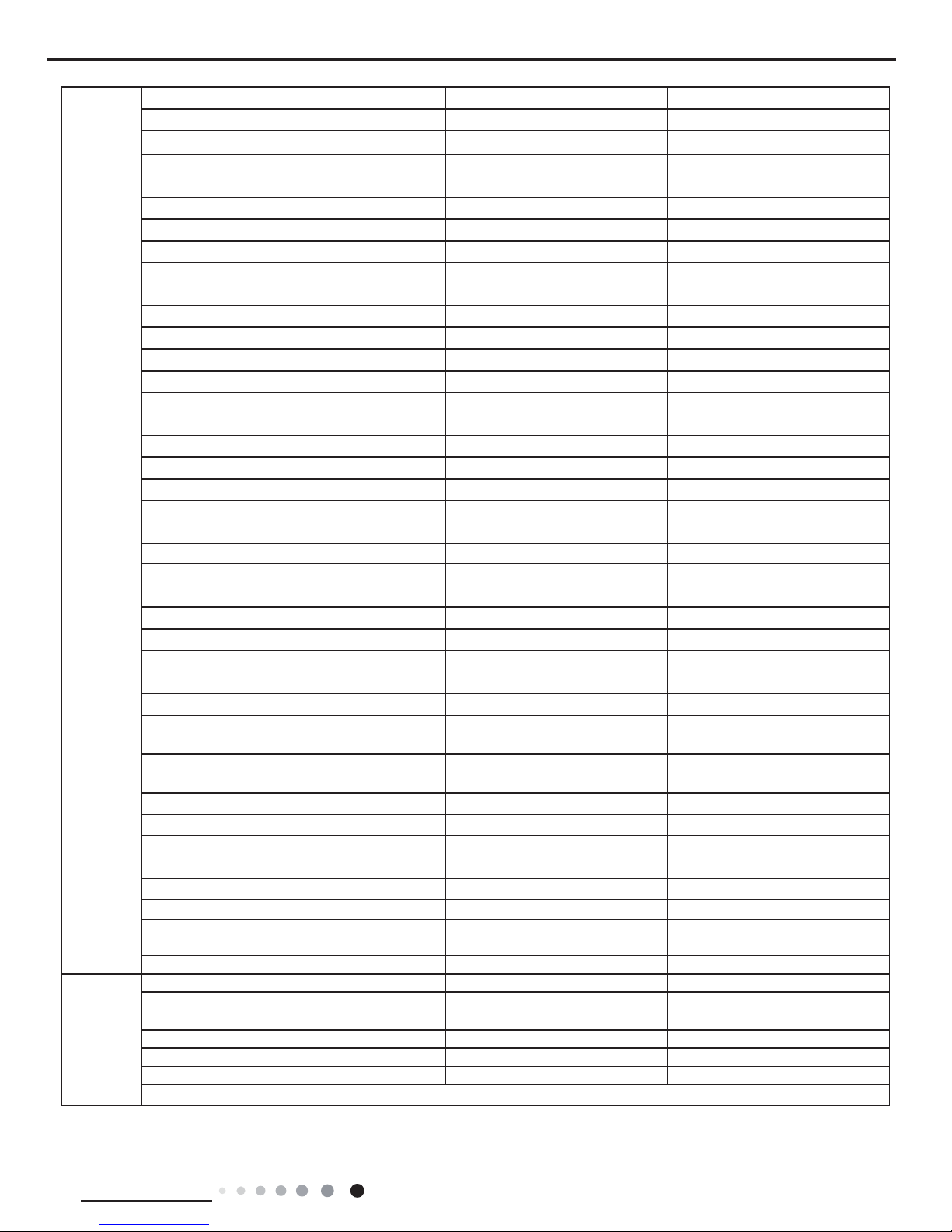
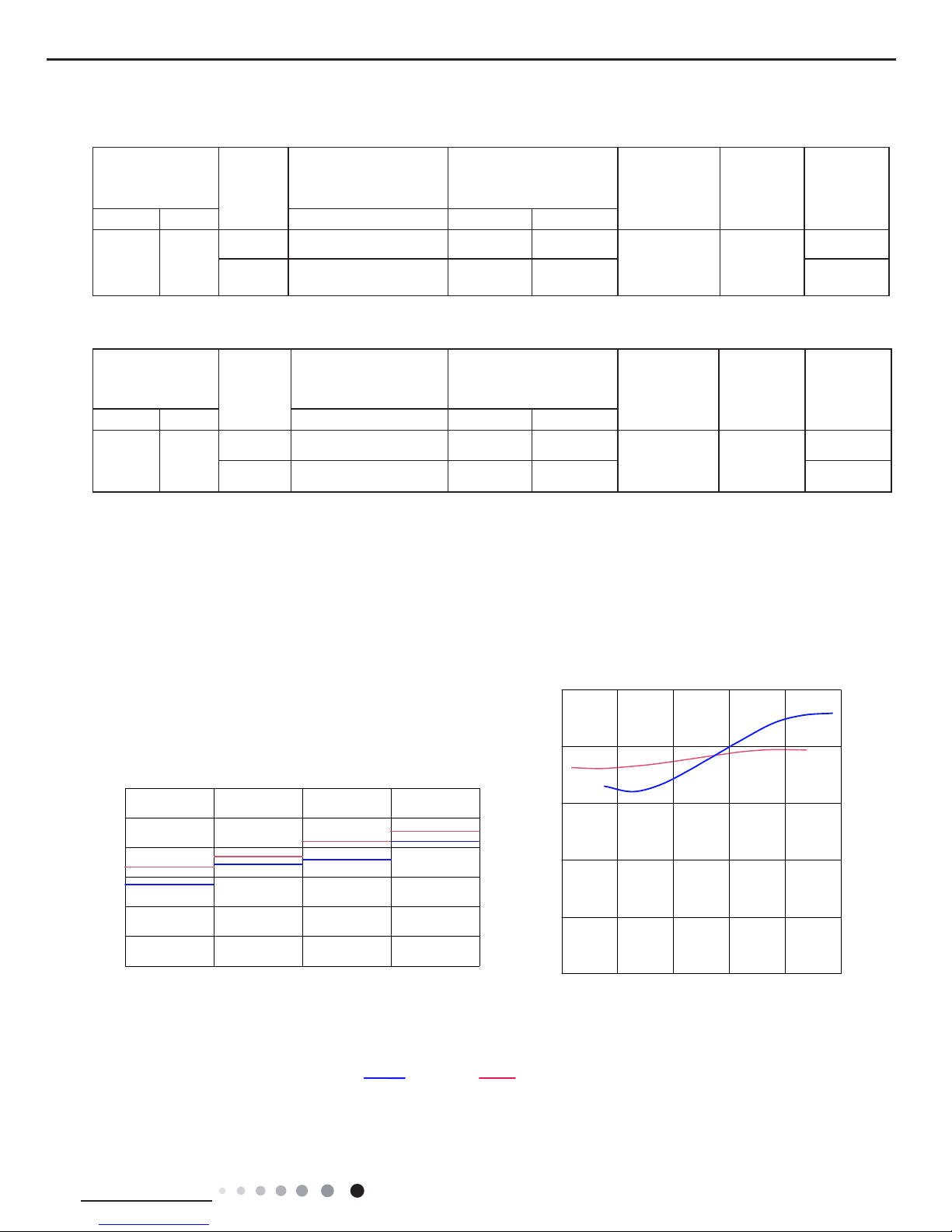
2.2 Operation Characteristic Curve
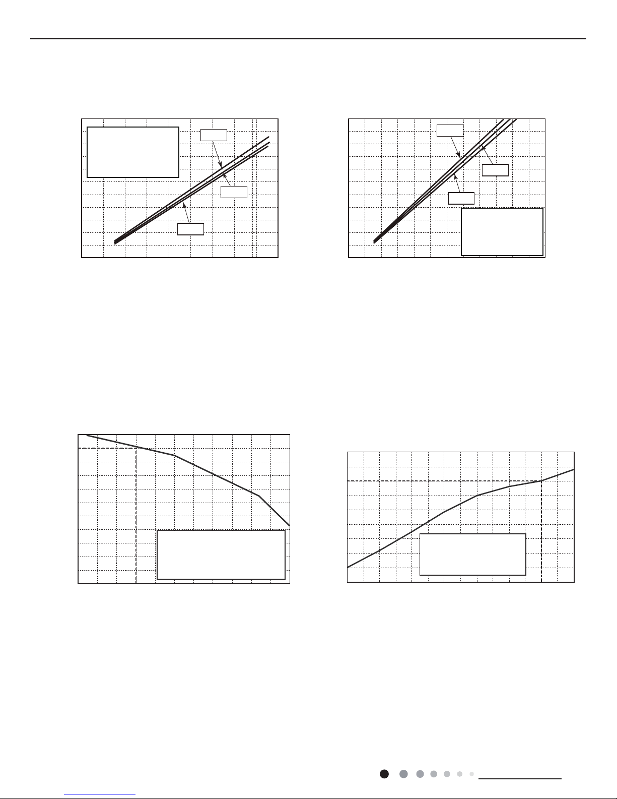
2.3 Capacity Variation Ratio According to Temperature
01020304050607090010 20 30 40 50 60 70 80 90 100 120 110
80
11
10
9
8
7
6
5
4
3
2
1
0
Compressor speed (rps)
) A ( t n e r r u C
11
10
9
8
7
6
5
4
3
2
1
0
Compressor speed (rps)
) A ( t n e r r u C
220V
230V
240V
220V
230V
240V
01020304050607090010 20 30 40 50 60 70 80 90 100
120
110
80
11
10
9
8
7
6
5
4
3
2
1
0
Compressor speed (rps)
)A(tnerruC
11
10
9
8
7
6
5
4
3
2
1
0
Compressor speed (rps)
)A(tnerruC
220V
230V
240V
220V
230V
240V
Conditions
Indoor: DB27°C/WB19°C
Outdoor: DB35°C/WB24°C
Indoor air flow: High
Pipe length: 5m
Conditions
Indoor: DB27°C/WB19°C
Outdoor: DB35°C/WB24°C
Indoor air flow: High
Pipe length: 5m
Conditions
Indoor: DB20°C/WB15°C
Outdoor: DB7°C/WB6°C
Indoor air flow: High
Pipe length: 5m
Conditions
Indoor: DB20°C/WB15°C
Outdoor: DB7°C/WB6°C
Indoor air flow: High
Pipe length: 5m
Cooling Heating
Cooling Heating
32 33 34 35 36 37 38 39 43
40 41 42
100
105
95
90
85
80
75
70
65
60
55
50
Conditions
Indoor:DB27°C/WB19°C
Indoor air flow:Super High
Pipe length: 5m
Outdoor temp.(°C)
Capacity ratio (%)
30
40
50
60
70
80
90
100
110
120
10
750-5-10-15-22
Outdoor temp.(oC)
Capacity ratio(%)
Conditions
Indoor:DB20°C/WB15°C
Indoor air flow:Super High
Pipe length: 5m
Cooling Heating
5
Technical Information
Service Manual
2.4 Cooling and Heating Data Sheet in Rated Frequency
Rated cooling
condition(oC)
(DB/WB)
Model
Pressure of gas pipe
connecting indoor and
outdoor unit
Inlet and outlet pipe
temperature of heat
exchanger
Fan speed of
indoor unit
Fan speed of
outdoor unit
Compressor
frequency
(Hz)
Indoor Outdoor P (MPa) T1 (oC) T2 (oC)
27/19 35/24
12K 0.8 ~ 1.1 11 to 14 38 to 41
Super High High
72
18K 0.8 ~ 1.0 12 to 14 80 to 40 52
Rated heating
condition(oC)
(DB/WB)
Model
Pressure of gas pipe
connecting indoor and
outdoor unit
Inlet and outlet pipe
temperature of heat
exchanger
Fan speed of
indoor unit
Fan speed of
outdoor unit
Compressor
frequency
(Hz)
Indoor Outdoor P (MPa) T1 (oC) T2 (oC)
20/15 7/6
12K 2.8 ~ 3.2 38 to 41 2 to 5
Super High High
77
18K 2.2 ~ 2.4 70 to 40 1 to 5 65
Instruction:
T1: Inlet and outlet pipe temperature of evaporator
T2: Inlet and outlet pipe temperature of condenser
P: Pressure at the side of big valve
Connection pipe length: 5 m.
Cooling:
Heating:
2.5 Noise Curve
Indoor side noise
60
50
40
30
20
10
0
Indoor Fan Motor Rotating Speed
Noice/dB(A)
low
Middle
High Super High
Outdoor side noise
Compressor frequency/Hz
Noise/dB(A)
70
60
50
40
30
02040608
0100
20
18K12K
6
Technical Information
Service Manual
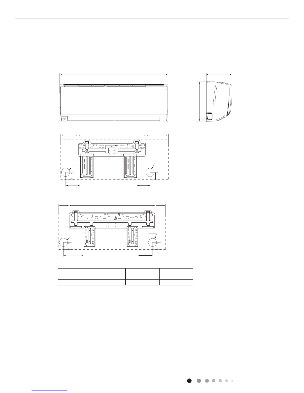
3. Outline Dimension Diagram
3.1 Indoor Unit
Unit:mm
104 685 181
140
190
38
Φ55
Φ55
38
90
150
54
168.5 462 159.5
Φ55
Φ55
54
W
D
H
12K
18K
Models W H D
12K 790 275 200
18K 970 300 224
7
Technical Information
Service Manual
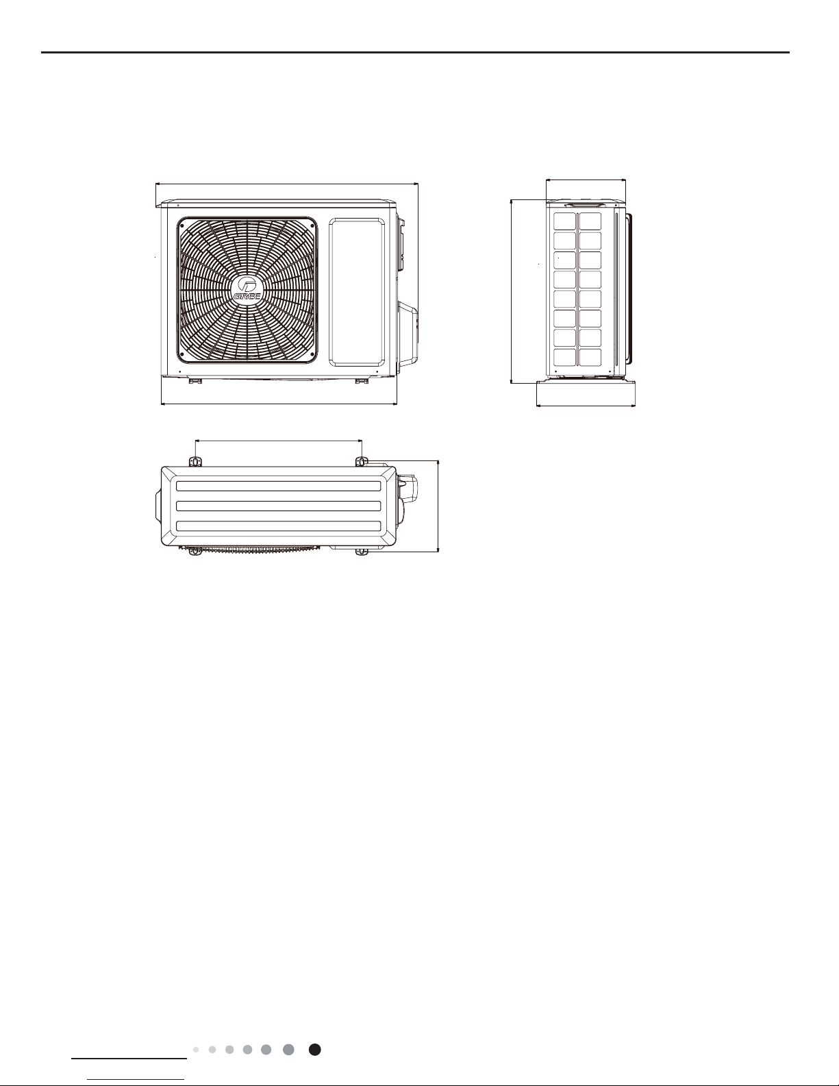
3.2 Outdoor Unit
Unit:m
m
540
297
842
257
320
596
763
8
Technical Information
Service Manual
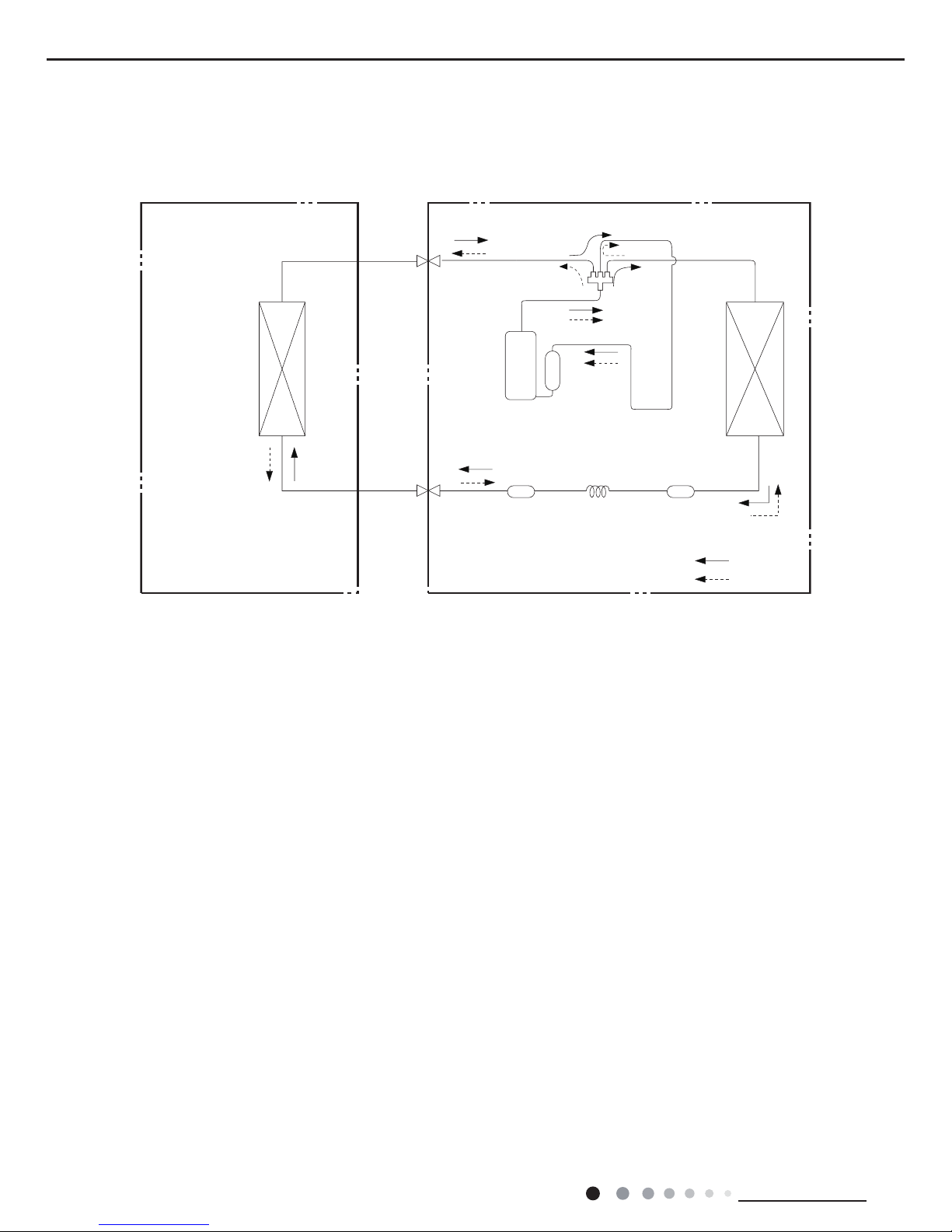
Indoor unit
Outdoor unit
COOLING
HEATING
4-Way valve
Discharge
Suction
Heat
exchanger
(evaporator)
Heat
exchanger
(condenser)
Valve
Valve
Liquid pipe
side
Gas pipe
side
Strainer CapillaryStrainer
Accumlator
Compressor
4. Refrigerant System Diagram
Connection pipe specication:
Liquid pipe:1/4" (6mm)
Gas pipe:3/8" (9.52mm)
Cooling and heating model

9
Technical Information
Service Manual
5. Electrical Part
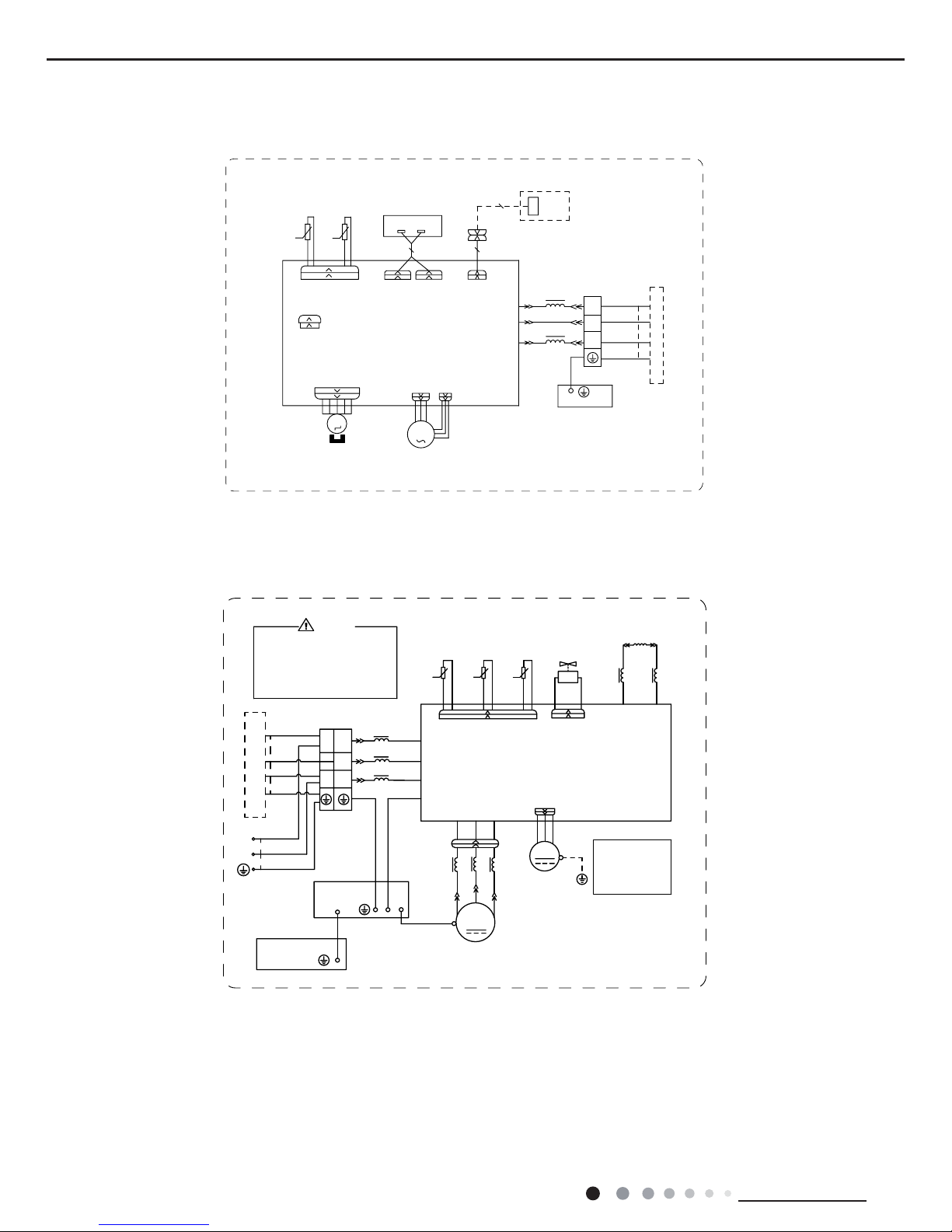
5.1 Wiring Diagram
● Indoor Unit
●Instruction
Symbol Symbol Color Symbol Symbol Color Symbol Name
WH White GN Green CAP Jumper cap
YE Yellow BN Brown COMP Compressor
RD Red BU Blue Grounding wire
YEGN Yellow/Green BK Black / /
VT Violet OG Orange / /
Note: Jumper cap is used to determine fan speed and the swing angle of horizontal lover for this model.
76(1625
7(03
6(1625
7(03
6(1625
57
5220
78%(
67(33,1*
',63/$<
35,17('&,5&8,7%2$5'
5(&(,9(5$1'
',63/$<%2$5'
&$%/(
&211(&7,1*
6:,1*8'
02725
%/2&.
7(50,1$/
$3
-803
&$3
%8
%.
<(*1
(9$325$725
3(
;7
1
0
287'22581,7
$3
3*
*(1(5$725
&2/'3/$60$
)$102725
0
5' %8
+($/7+1
+($/7+/
3*)
',63
',63
%1
<(*1
57
1
&20287
/
%8
%.
%1
/
/
:,),02'8/(
$3
&200$18$/
:,),
6363222005
GWH12QB-K3DNA6D/I(CB427N04702) GWH12QB-K3DNA5D/I GWH18QD-K3DNA6E/I(CB427N06400)
GWH18QD-K3DNA5E/I
10
Technical Information
Service Manual
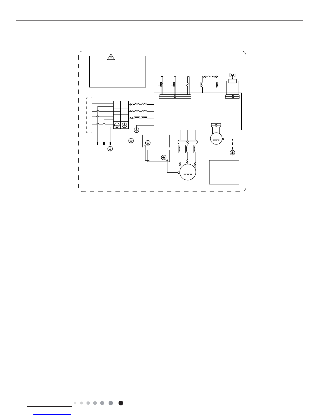
● Outdoor Unit
63610000453
%1
%.
%8
/
/
/
/
/
5,1*
0$*1(7,&
3(
/
%8
9
5'
<(
/;
/;
7(50,1$/
1
/
1
/
1
&1
2)$1
:
9
8
$30DLQ%RDUG
1
$&/
&208
3(
/
/
5($&725
/
%8
%1
7(03
6(1625
7(03
6(1625
7(03
57
57
57
6(1625
<9
:$<
:$<
0$*1(7,&
5,1*
N
N
N
0$*1(7,&
5,1*
;
0,',62/$7,21
6+((7
<(*1
3(
3(
<(*1
<(*1
<(*1
<(*1*1
9$/9(
28778%(
2875220
(;+$867
%/2&.
%8
%.
%1
%8:+
%1%.
97
97
WKHULVNRIHOHFWULFVKRFN
3OHDVHGRQWWRXFKDQ\
WHUPLQDOZKHQWKHPDFKLQH
LVUXQQLQJVWRSSLQJRUKDV
EHHQSRZHUHGRIIIRUOHVV
WKDQPLQXWHVWRSUHYHQW
:$51,1*
%8
<(
5'
<(*1
,1'22581,7
:
8
&203
&203
;7
32:(5
)$1
0
3(
3(
127(
0RWRU
DSSOLHVWRWKH
LURQVKHOOPRWRU
JURXQG
(/(&75,&$/
%2;
<(*1
02725
RQO\
GWH12QB-K3DNA6D/O
6363222004
GWH12QB-K3DNC4D/I GWH12QB-K3DNE2D/I GWH18QD-K3DNC4E/I GWH18QD-K3DNE2E/I
GWH12QB-K3DNA6D/I(CB427N04703) GWH18QD-K3DNA6E/I(CB427N06401)
76(1625
7(03
6(1625
7(03
6(1625
57
5220
78%(
67(33,1*
',63/$<
35,17('&,5&8,7%2$5'
5(&(,9(5$1'
',63/$<%2$5'
&$%/(
&211(&7,1*
6:,1*8'
02725
%/2&.
7(50,1$/
$3
-803
&$3
%8
%.
<(*1
(9$325$725
3(
;7
1
0
287'22581,7
$3
3*
)$102725
0
3*)
',63
',63
%1
<(*1
57
1
&20287
/
%8
%.
%1
/
/
:,),02'8/(
$3
&200$18$/
:,),
11
Technical Information
Service Manual
These circuit diagrams are subject to change without notice, please refer to the one supplied with the unit.
GWH18QD-K3DNA6E/O
%1
8
9
:
78%(
6(1625
57
57
57
&1
/
)$1
2)$1
&203
&203
3(
0
3(
3(
0,',62/$7,21
(/(&75,&
$335,17('&,5&8,7%2$5'
$&/
/
/
(
/;
/;
/
%.
%8
<(*1
<(*1
%1%8
%8
%8
5'
5'
<(
<(
6(1625
2875220
(;+$867
6(1625
/
/
/
:
9
8
/
/
1
&208
7(03
7(03
7(03
,1'22581,7
6+((7
02725
/
.
.
.
RIHOHFWULFVKRFN
3OHDVHGRQWWRXFKDQ\
WHUPLQDOZKHQWKHPDFKLQHLV
UXQQLQJVWRSSLQJRUKDVEHHQ
SRZHUHGRIIIRUOHVVWKDQ
PLQXWHVWRSUHYHQWWKHULVN
:$51,1*
5($&725
3(
0$*1(7,&
5,1*
<(*1
%2;
<(*1
3(
/
/
:$<
<9
:$<
9$/9(
97
97
%/2&.
7(50,1$/
;7
1
%8
%.
%1
<(*1
/
32:(5
3(
<(*1
%8
%1%.
<(*1
;
127(
0RWRU
WRWKH
VKHOOPRWRU
JURXQG
RQO\
DSSOLHV
LURQ
1
/
N
63610000467
12
Technical Information
Service Manual
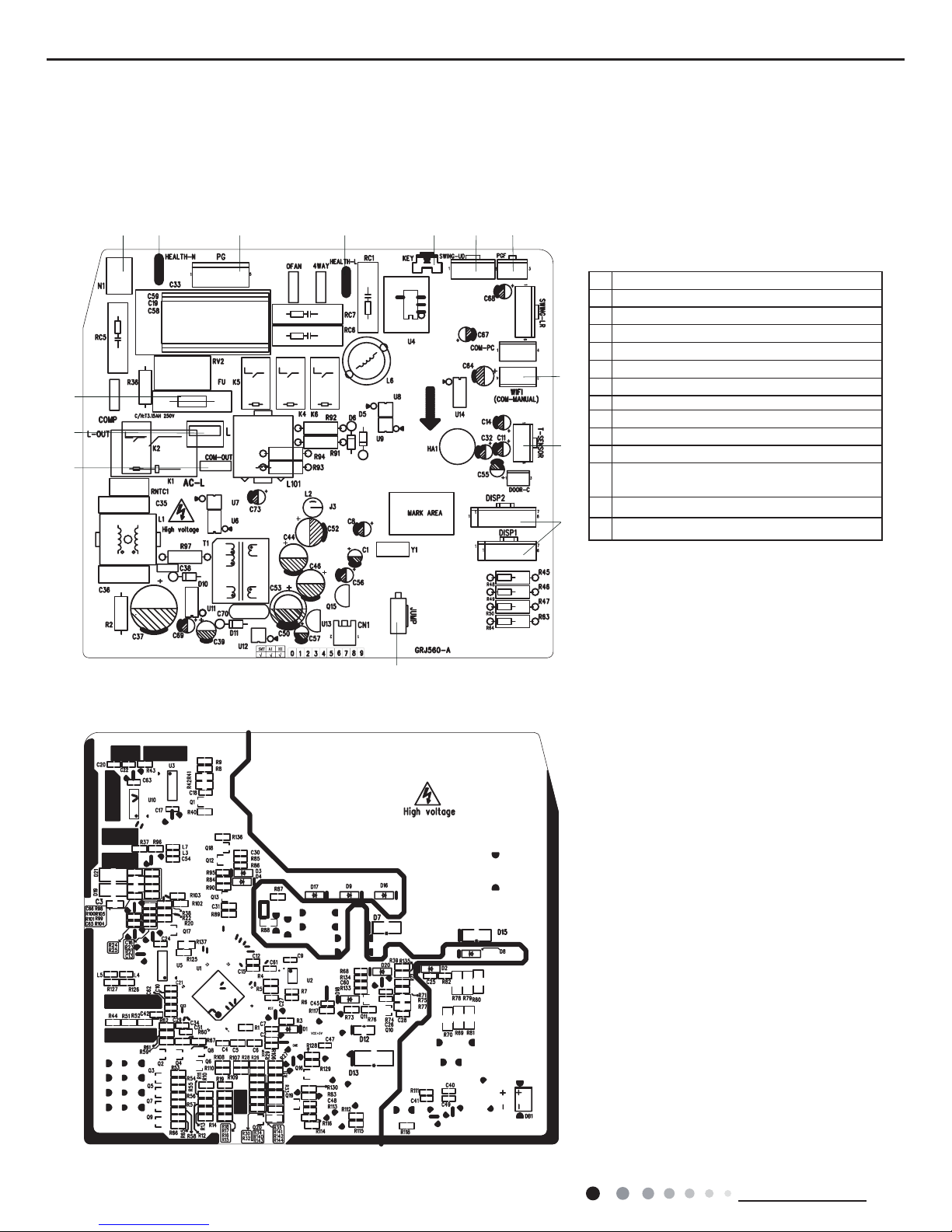
5.2 PCB Printed Diagram
Indoor Unit
● Top view
● Bottom view
1 Neutral wire terminal
2Interface of health function neutral wire
3Motor needle stand
4Interface of health function live wire
5Auto button
6 Up&down swing motor
7Interface of up & down swing motor
8WIFI
Fuse
9 Temperature sensor
10 Terminal for display board connection
11 Jump
12
Terminal with outdoor unit communicatio
n
wire
1314Live wire terminal
12 34
567
8
9
11
12
13
14
10

13
Technical Information
Service Manual
1
2
3411
5
6
7
8
9
10
Outdoor Unit
● Top view
● Bottom view
No. Name
1 Reactor wiring terminal
2 Compressor wiring terminal
3
Terminal of outdoor unit temperature
sensor
4
Compressor overload protection
terminal
5
Terminal with indoor unit communication
wire
6
Terminal of power supply live wire
terminal
7 Terminal of power supply neutral wire
8 Interface of earthing wire
9 Terminal of outdoor fan
10 Interface of 4-way valve
11 Terminal of electronic expansion valve
14
Technical Information
Service Manual
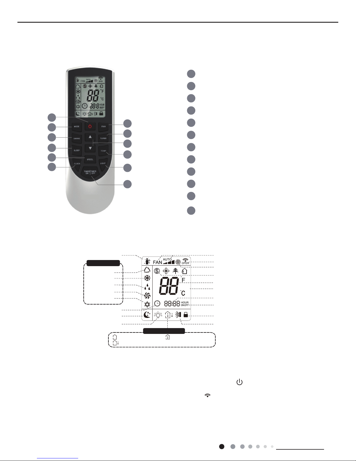
6. Function and Control
6.1 Remote Controller Introduction
Introduction for icons on display screen
Introduction for buttons on remote controller
1
5
3
6
8
10
12
11
9
7
4
2
1
2
3
4
5
6
7
8
9
10
11
12
ON/OFF button
MODE button
FAN button
SWING button
TURBO button
TEMP button
I FEEL button
LIGHT button
CLOCK button
TIMER ON / TIMER OFF
button
SLEEP button
▲/ button
▲
Note:
● This is a general use remote controller, it could be used for the air conditioners with multifunction; For some function, which the
model doesnt have, if press the corresponding button on the remote controller that the unit will keep the original running status.
● After putting through the power, the air conditioner will give out a sound. Operation indictor " " is ON (red indicator). After that,
you can operate the air conditioner by using remote controller.
●
Under on status, pressing the button on the remote controller, the signal icon " "
on the display of remote controller will blink once
and the air conditioner will give out a “de” sound, which means the signal has been sent to the air conditioner.
● Under off status, set temperature and clock icon will be displayed on the display
of remote controller (If timer on, timer off and light functions are set, the corre- sponding icons will be displayed on the display of
remote controller at the same
time); Under on status, the display will show the corresponding set function icons.
WIFI
Send signal
Turbo mode
8℃ heating function
Set temperature
Set time
TIMER ON / TIMER OFF
Child lock
Up & down swing
Set fan speed
Light
Temp. display type
:Set temp.
:Outdoor ambient temp.
:Indoor ambient temp.
Sleep mode
Clock
Heat mode
Fan mode
Dry mode
Cool mode
Auto mode
Operation mode
I feel
WIFI
WIFI
15
Technical Information
Service Manual
Press this button to turn on the unit. Press this button again to turn off the unit.
Press this button to increase set temperature. Holding it down above 2 seconds rapidly increases set temperature.
In AUTO mode, set temperature is not adjustable.
AUTO
COOL DRY FAN
HEAT
*
OFF
Caution:
16
Technical Information
Service Manual
Combination “MODE” and “TURBO” buttons:
Press "MODE" and "TURBO" button simultaneously to turn on or turn off WIFI function. When WIFI function is turned on,
the " " icon will be displayed on remote controller; Long press "MODE" and "TURBO" buttons simultaneously for 10s,
remote controller will send WIFI reset code and then the WIFI function will be turned on. WIFI function is defaulted ON
after energization of the remote controller.
12.TURBO button
About WIFI fuction
17
Technical Information
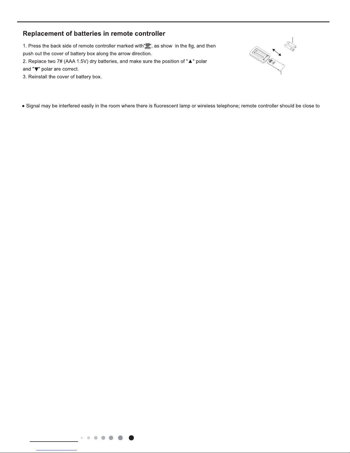
Service Manual
battery
Cover of battery box
remove
reinstall
● During operation, point the remote control signal sender at the receiving window on indoor unit.
● The distance between signal sender and receiving window should be no more than 8m, and there should be no obstacles between them.
indoor unit during operation.
● Replace new batteries of the same model when replacement is required.
● When you don’t use remote controller for a long time, please take out the batteries.
● If the display on remote controller is fuzzy or there’s no display, please replace batteries.
Note:
18
Technical Information
Service Manual
NOTE:One AC can be controlled by 4 cell phone in maximun at the same time.
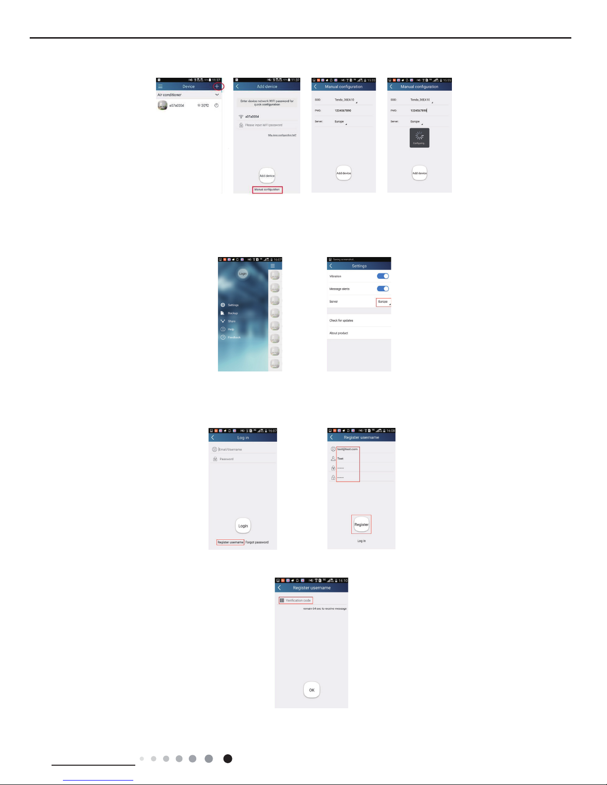
2.Short-distance and long-distance control setting for air conditioner connecting router
Step 1: Under short-distance control, return to the homepage "Home Control". Tap at the top right corner of the homepage "Home
control". Select "Add device" and enter the page of "Add device". Tap "Manual conguration" and enter the page "Manual conguration".
Step 2: Select the correct network name and enter the password,select the server (The server setting here must keep the same as the
server setting in "Settings" mentioned below.Otherwise, remote control will be failed.),then tap the button "Add device" for conguration. If
conguration succeeds, App will notify user that conguration is successful and return to homepage.
6.2 Operation of Smart Control (Smart Phone, Tablet PC) For Gree
Operation Instructions
Download and install APP
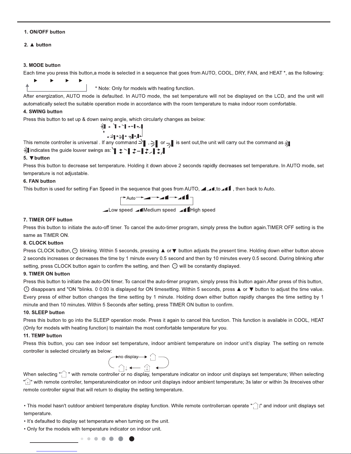
Scan the following QR code with your smart phone and download Wi Smart.
Conguration
Before operation, please nish the following conguration in order to realize Wi control and the connection between air conditioner and
intelligent device.
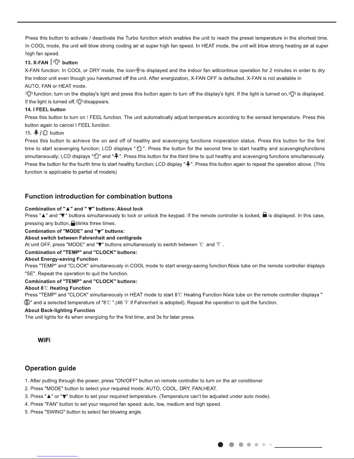
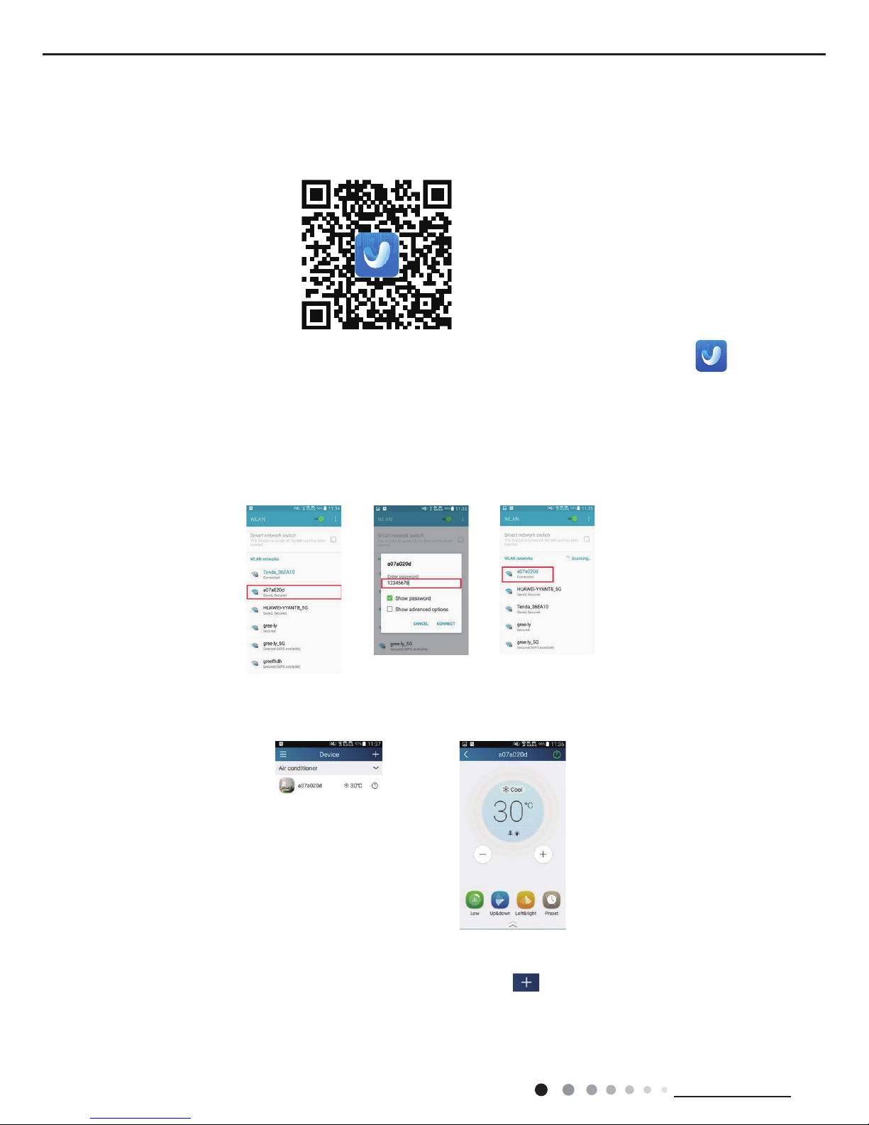
1.Short-distance control setting for air conditioner using wi hotspotStep 1: Air conditioner wi is set to AP mode in factory. You can
search the air conditioner wi hotspot through your smart phone. The name of wi hotspot is the last 8 numbers of the air conditioner
mac address. Password is 12345678.
Step 2: Open App and the screen will show the air conditioner that you just connected. Click this air conditioner to enter and realize
short-distance control, as shown below. Please refer to "Functions introduction" for specic control methods.
Install the App according to its guidance. When successfully installed, your smart phone homepage will show this icon
19
Technical Information
Service Manual
Functions introduction
1.User registration
Purpose: To realize long-distance control
Operation instruction: For the rst time login, you have to register a new username. If you already have a username, skip the registration
step and enter email address and password on the "Login Page" to log in. If password is forgotton, you can reset the password.
Operation steps:
(1) Select the sever address
(2) Account login: Slide the page "Device". and enter the page "Menu" on the left. Tap "Login" to enter the page "Register username".
New user must rst register a username. Tap "Register”.
(3) Enter your email address. Wait until you receive the verication code. Enter the code and then tap "OK" to log in. Username will
appear. As shown here, the username is "test".
NOTICE:
Please select the encrypt mode "empty" if your wi has been set without password.
20
Technical Information
Service Manual
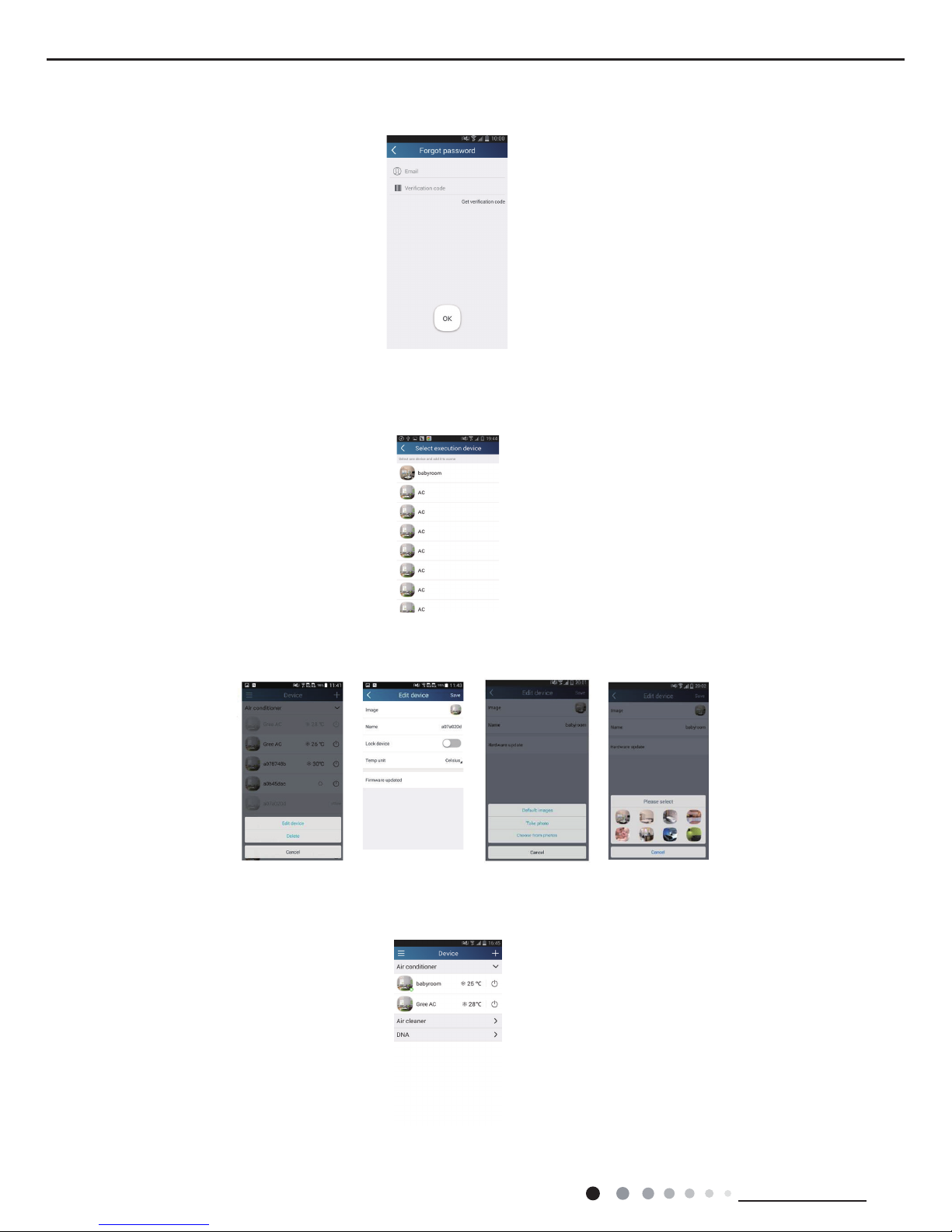
(4) If password is forgotten, you can reset the password with your email address.
Tap "Forgot password" and enter the page "Forgot password". Tap "Get verication code" to get a email verication code. Enter a new
password and tap "OK" to log in.
2.Personal settings
Purpose: Set name (device name, preset name, etc.) and images (device image) in order to identify a user easily.
(1) Set device name
After quick conguration, a list of controllable smart devices will be generated. Default name for air conditioner is the last 8 numbers of the
air condtioner mac address.
Step 1: Tap and hold "babyroom" to enter the page "Edit device". Tap "Image" to select the source of image. Select from "Default images"
or "Take photo" or "Choose from photos" and save an image.
Step 2: Tap "Name" to change device name, Save it and the new device name will be shown. enable button Lock device to lock the device
other smart phone cant search the device now. Tap "Temp unit" to change the temperature unit.
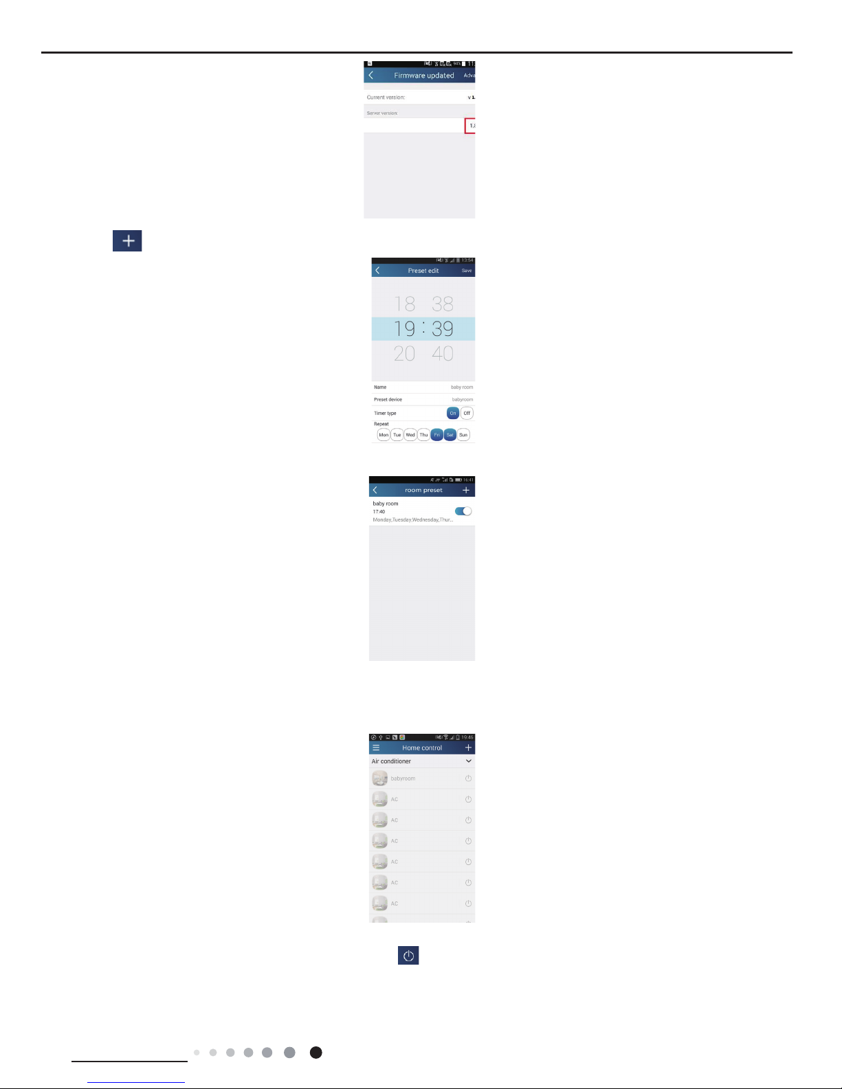
Step 3: Tap "Firmware updated" to upgrade the Firmware of the device, Tap"1.8" the device will upgraded auto.
21
Technical Information
Service Manual
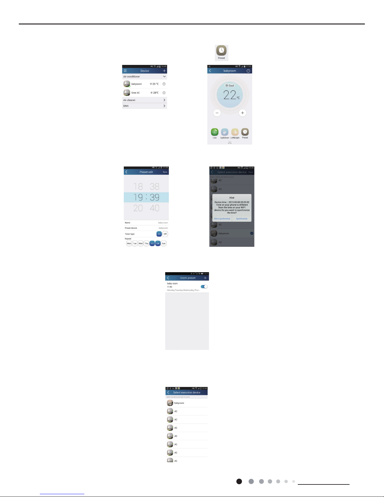
(2) Set preset name
Step 1: Tap at the top right corner of the homepage "Device". Select "Add preset" and enter the page "Preset edit".
Step 2: Choose the time. Tap "Name". As shown in the picture, its name is "baby room". For timer type, select "On". Then select the repeating
days. Save the setting of preset name.
(3) Set device image
Please refer to step 1 in 2(1)
3.Control functions
(1) Common control functions: General control on the operation of smart devices (On/Off, temperature, fan speed, mode, etc.) and the setting
of advanced functions (air exchange, dry, health, light, sleep, energy saving upper limit).
Step 1: General control Enter the homepage "Home control" rst. Take "baby home"as an example.
Tap "babyroom" and enter the page of air conditioner control. Tap to turn on the control switch.
22
Technical Information
Service Manual
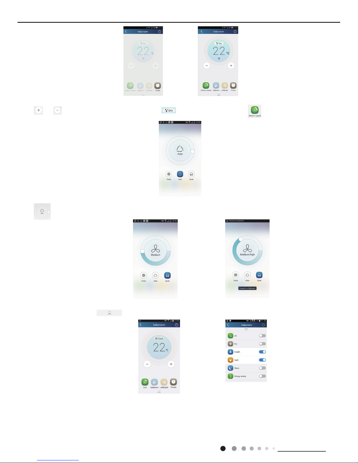
Tap or to increase or decrease temperature. Tap to change working mode. Tap to enter the page of fan speed
adjustment.
Tap and go around the circle to adjust fan speed.
Step 2: Advanced settings Tap to enter advanced settings. You may select "Air", "Dry", "Health", "Light", "Sleep" or "Energy
saving".
(2) Advanced control functions: Set scene; Preset; Link: Infrared control (only applicable to smart phone with infrared emitter)
Set scene: Preset the operation of several smart devices by one tap.
On the page "Home control", tap the image of "Home control" to enter the page "Edit scene".

23
Technical Information
Service Manual
Tap "Add scene" and edit the scene name, for example, "Back home". Add execution devices.
Tap to add commands. On the page "Select execution device", select the air conditioner named "babyroom". Then select "ON" or
"OFF".
Continue to select the next execution device as instructed above. Tap to set the interval.
Tap "Save". Then the scene "Back home" will be in execution. You may view the execution condition of the scene.
24
Technical Information
Service Manual
(3) Preset includes single-device preset and multi-device preset Single-device preset: This can preset a certain device to be On/Off at a
specic time.
On the homepage "Device", take air conditioner "babyroom" as an example.Tap at the bottom of the page "babyroom". Then you will
enter the page "Preset edit".
Slide up and down to set the time. If you want to synchronize the time, tap " synchronize".
Tap "Name" to customize the preset name.
Preset device cant be selected and it will default to "babyroom". Select "On" for the timer type. Select repeating days to complete the
preset.
Multi-device preset: This can preset multiple devices to execute a command at a specic time.
Please refer to the instructions as how to set preset time, name, timer type and repeating days for a single device.
Tap "Preset device" to select one or more devices. Then return to the page "Device".
25
Technical Information
Service Manual
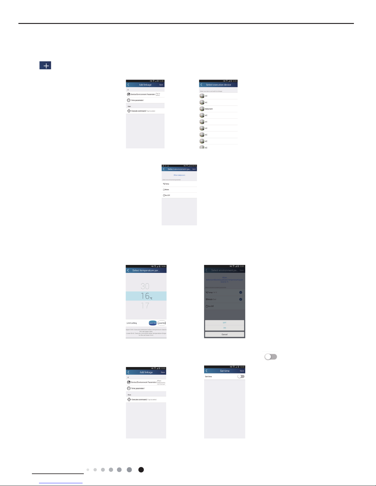
(4) Link(This function is applicable to partial of models)
set in the master device, slave devices will execute commands to realize devices Select a master device. When the environment has
satised the parameters as linkage.
Step 1: Set the parameters of master device (Select master device, select environment parameters, select master device status).
Tap at the top right corner of the homepage "Home control". Select "Link" and enter the page "Add linkage". Tap "Device
parameter" to enter the page "Select device". Take "baby room" as an example. Tap "baby room".
Enter the page "Select environment parameters".
Tap "Temperature" to enter the page "Select temperature parameter". Slide up or down to adjust temperature. Tap "Upper limit" or
"Lower limit".
Tap "Mode" and "On/Off" to select the status of master device. Then tap "Save".
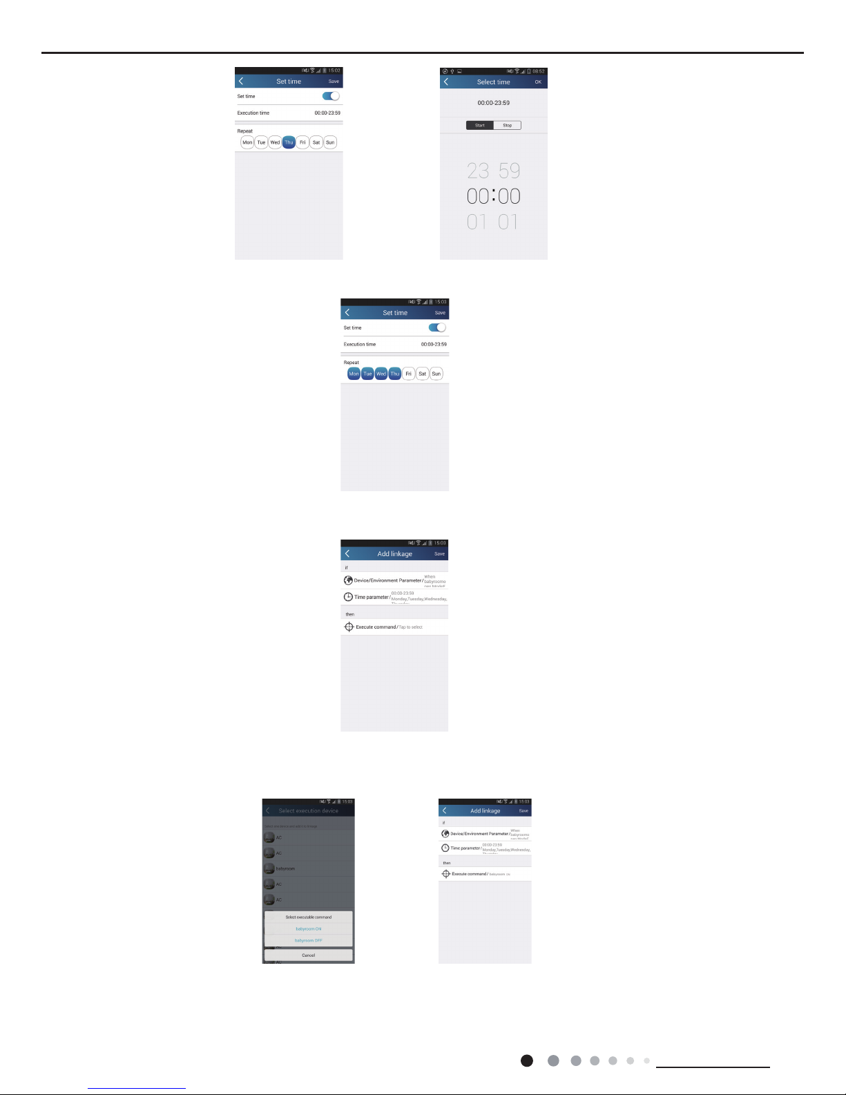
Step 2: Set time parameter for linkage. Tap "Time parameter" to enter the page "Set time". Slide rightwards to turn on the
setting time.
Tap "Execution time"; Then tap "Start" and "Stop" to set start time and stop time respectively. Tap "OK" at the top right corner to save
the setting.
26
Technical Information
Service Manual
Tap the days below "Repeat" to select the repeating days. Then tap "Save".
Step 3: Select "Execute command"
Tap "Execute command" and enter the page "Select device".
Tap the name of device that you want to control. Tap "ON" or "OFF" and then tap "Save" to complete the linkage.
Tap "Save" and then repeat the above steps to set linkage of several scenes.
27
Technical Information
Service Manual
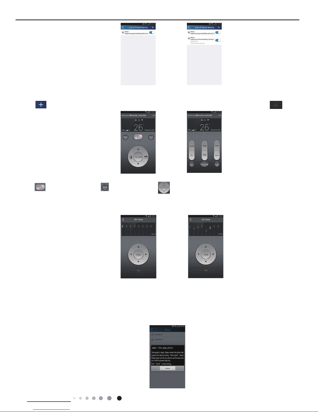
(5) Infrared control (only applicable to smart phone with infrared emitter).
Function: Smart phone can be used as a remote controller.
Tap at the top right corner of the homepage "Device". Select "Infrared" and enter the page "Remote controller". Tap and
slide up to enter the page of advanced functions.
Tap to turn on the device. Tap to select mode. Tap to adjust fan speed and swing angle. Tap "Health", "Energy
saving", "Sleep" etc. to set advanced functions.
Tap "Sleep" to enter the page "Sleep". You can select "Traditional sleep", "Expert sleep" or "DIY sleep". Tap "DIY sleep" and then tap
the left and right arrows to set sleep time. Tap up and down arrows to adjust temperature at a specic sleep time.
4.Menu functions
Menu functions (Share, Set, History, Feedback)
(1) Share: To share quick conguration information and units information, including local export and local import.
For local import, you just need to tap "Local import" and wait for the data download.
Local export
Step 1: Export local data to another smart phone.
Enter "Menu" on the left side and tap "Share" to enter the page "Share". Then tap "Local export".
 Loading...