

Gree GWC18QD-D3DNA6E/I, GWC18QD-D3DNB4E/I, GWC18QD-D3DNB2E/I, GWC18QD-D3DNB2E (LC), GWC18QD-D3DNA5E(LC) Service Manual
...
GREE ELECTRIC APPLIANCES,INC.OF ZHUHAI
Change for Life
Service Manual

Service Manual
Table of contents
Table of Contents
Part
Ⅰ
: Technical Information
.......................................................................1
1. Summary
......................................................................................................................1
2. Specications
..........................................................................................................3
2.1 Specication Sheet ...........................................................................................................3
2.2 Operation Characteristic Curve ........................................................................................7
2.3 Capacity Variation Ratio According to Temperature .........................................................7
2.4 Noise Curve ......................................................................................................................8
2.5 Cooling and Heating Data Sheet in Rated Frequency .....................................................8
3. Outline Dimension Diagram
........................................................................9
3.1 Indoor Unit ........................................................................................................................9
3.2 Outdoor Unit ...................................................................................................................10
4. Refrigerant System Diagram
.................................................................... 11
5. Electrical Part
.........................................................................................................12
5.1 Wiring Diagram ...............................................................................................................12
5.2 PCB Printed Diagram .....................................................................................................14
6. Function and Control
......................................................................................16
6.1 Remote Controller Introduction .....................................................................................16
6.2 Brief Description of Modes and Functions ......................................................................20
Part
Ⅱ
: Installation and Maintenance
.................................................29
7. Notes for Installation and Maintenance
..........................................29
8. Installation
................................................................................................................31
8.1 Installation Dimension Diagram ......................................................................................31
8.2 Installation Parts-checking ............................................................................................33
8.3 Selection of Installation Location ....................................................................................33
8.4 Electric Connection Requirement ..................................................................................33
8.5 Installation of Indoor Unit ................................................................................................33
8.6 Installation of Outdoor Unit .............................................................................................36
8.7 Vacuum Pumping and Leak Detection ...........................................................................37
8.8 Check after Installation and Test Operation ...................................................................37

Service Manual
9. Maintenance
............................................................................................................38
9.1 Precautions before Maintenance ....................................................................................38
9.2 Error Code List ...............................................................................................................39
9.3 Troubleshooting for Main Malfunction ............................................................................42
9.4 Troubleshooting for Normal Malfunction .........................................................................56
10. Exploded View and Parts List
..............................................................58
10.1 Indoor Unit ....................................................................................................................58
10.2 Outdoor Unit .................................................................................................................76
11. Removal Procedure
.......................................................................................80
11.1 Removal Procedure of Indoor Unit ...............................................................................80
11.2 Removal Procedure of Outdoor Unit ............................................................................85
Appendix:
........................................................................................................................90
Appendix 1: Reference Sheet of Celsius and Fahrenheit ....................................................90
Appendix 2: Conguration of Connection Pipe .....................................................................90
Appendix 3: Pipe Expanding Method ...................................................................................91
Appendix 4: List of Resistance for Temperature Sensor ......................................................92
1
Technical Information
Service Manual
1. Summary
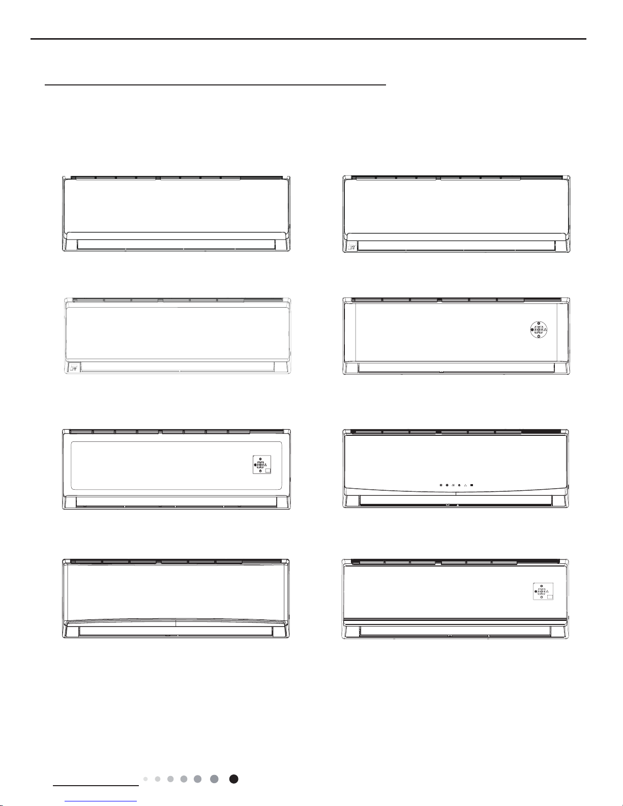
Indoor Unit:
Part
Ⅰ
: Technical Information
A6 Panel
B4 Panel
B2 Panel
C2 Panel
B8 Panel A1 Panel
GWH18QD-D3DNA5E/I(CB425N04701 CB425N04702)
GWH24QE-D3DNA5E/I(CB425N05001 CB425N05002)
GWH18QD-D3DNA5E/I(CB425N04700)
GWC18QD-D3DNA5E/I GWC24QE-D3DNA5E/I
GWH24QE-D3DNA5E/I(CB425N05000 )
2
Technical Information
Service Manual
Model List:
No Model Product code Indoor model
Indoor product
code
Outdoor model
Outdoor product
code
1 GWC18QD-D3DNA6E(LC) CB427001700 GWC18QD-D3DNA6E/I CB427N01700
GWC18QD-D3DNA6E/O(LC) CB427W01700
2 GWC18QD-D3DNB4E(LC) CB434001500 GWC18QD-D3DNB4E/I CB434N01500
3 GWC18QD-D3DNB2E(LC) CB432002700 GWC18QD-D3DNB2E/I CB432N02700
4 GWC18QD-D3DNA5E(LC) CB425004800 GWC18QD-D3DNA5E/I CB425N04800
5 GWC18QD-D3DNC2E (LC) CB439000500 GWC18QD-D3DNC2E/I CB439N00500
6 GWC18QD-D3DNB8E(LC) CB438001900 GWC18QD-D3DNB8E/I CB438N01900
7 GWC18QD-D3DNA1E(LC)
CB419007900
GWC18QD-D3DNA1E/I CB419N07900
8 GWH18QD-D3DNA1E(LCLH) CB419008000 GWH18QD-D3DNA1E/I CB419N08000
GWH18QD-D3DNA6E/O(LCLH) CB427W02000
9 GH18QD-D3DNA6E(LCLH) CB427002000 GWH18QD-D3DNA6E/I CB427N02000
10 GWH18QD-D3DNB4E(LCLH) CB434001200 GWH18QD-D3DNB4E/I CB434N01200
11 GWH18QD-D3DNB2E(LCLH) CB432002800 GWH18QD-D3DNB2E/I CB432N02800
12
GWH18QD-D3DNA5E(LCLH)
CB425004700
GWH18QD-D3DNA5E/I
CB425N04700
13 CB425004701 CB425N04701
14 CB425004702 CB425N04702
15 GWH18QD-D3DNC2E(LCLH) CB439000600 GWH18QD-D3DNC2E/I CB439N00600
16 GWH18QD-D3DNB8E(LCLH) CB438001500 GWH18QD-D3DNB8E/I CB438N01500
17 GWC24QE-D3DNA6E(LC) CB427002300 GWC24QE-D3DNA6E/I CB427N02300
GWC24QE-D3DNA6E/O(LC) CB427W02300
18 GWC24QE-D3DNB4E(LC) CB434001900 GWC24QE-D3DNB4E/I CB434N01900
19 GWC24QE-D3DNB2E(LC) CB432003000 GWC24QE-D3DNB2E/I CB432N03000
20 GWC24QE-D3DNA5E(LC) CB425004900 GWC24QE-D3DNA5E/I CB425N04900
21 GWC24QE-D3DNC2E(LC) CB439000700 GWC24QE-D3DNC2E/I CB439N00700
22 GWC24QE-D3DNB8E(LC) CB438001700 GWC24QE-D3DNB8E/I CB438N01700
23 GWC24QE-D3DNA1E(LC) CB419007200 GWC24QE-D3DNA1E/I CB419N07200
24 GWH24QE-D3DNA1E(LCLH) CB419007800 GWH24QE-D3DNA1E/I CB419N07800
25 GWH24QE-D3DNA6E(LCLH) CB427002400 GWH24QE-D3DNA6E/I CB427N02400
GWH24QE-D3DNA6E/O(LCLH) CB427W02400
26 GWH24QE-D3DNB4E(LCLH) CB434001400 GWH24QE-D3DNB4E/I CB434N01400
27 GWH24QE-D3DNB2E(LCLH) CB432002900 GWH24QE-D3DNB2E/I CB432N02900
28 GWH24QE-D3DNC2E(LCLH) CB439001500 GWH24QE-D3DNC2E/I CB439N01500
29
GWH24QE-D3DNA5E(LCLH)
CB425005000
GWH24QE-D3DNA5E/I
CB425N05000
30 CB425005001 CB425N05001
31 CB425005002 CB425N05002
32 GWH24QE-D3DNB8E(LCLH) CB438001800 GWH24QE-D3DNB8E/I CB438N01800
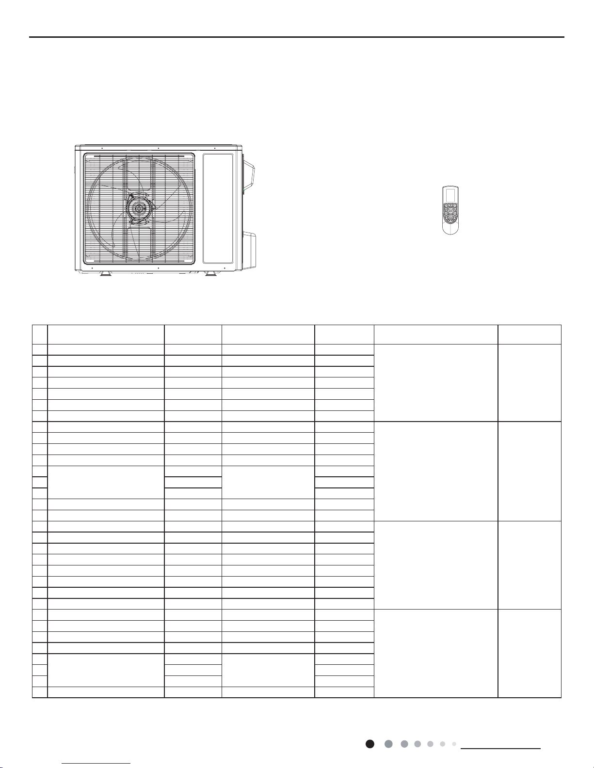
Outdoor Unit:
GWC18QD-D3DNA6E/O(LC)
GWH18QD-D3DNA6E/O(LCLH)
GWC24QE-D3DNA6E/O(LC)
GWH24QE-D3DNA6E/O(LC)(LH)
Remote Controller:
YAN1F1F
3
Technical Information
Service Manual
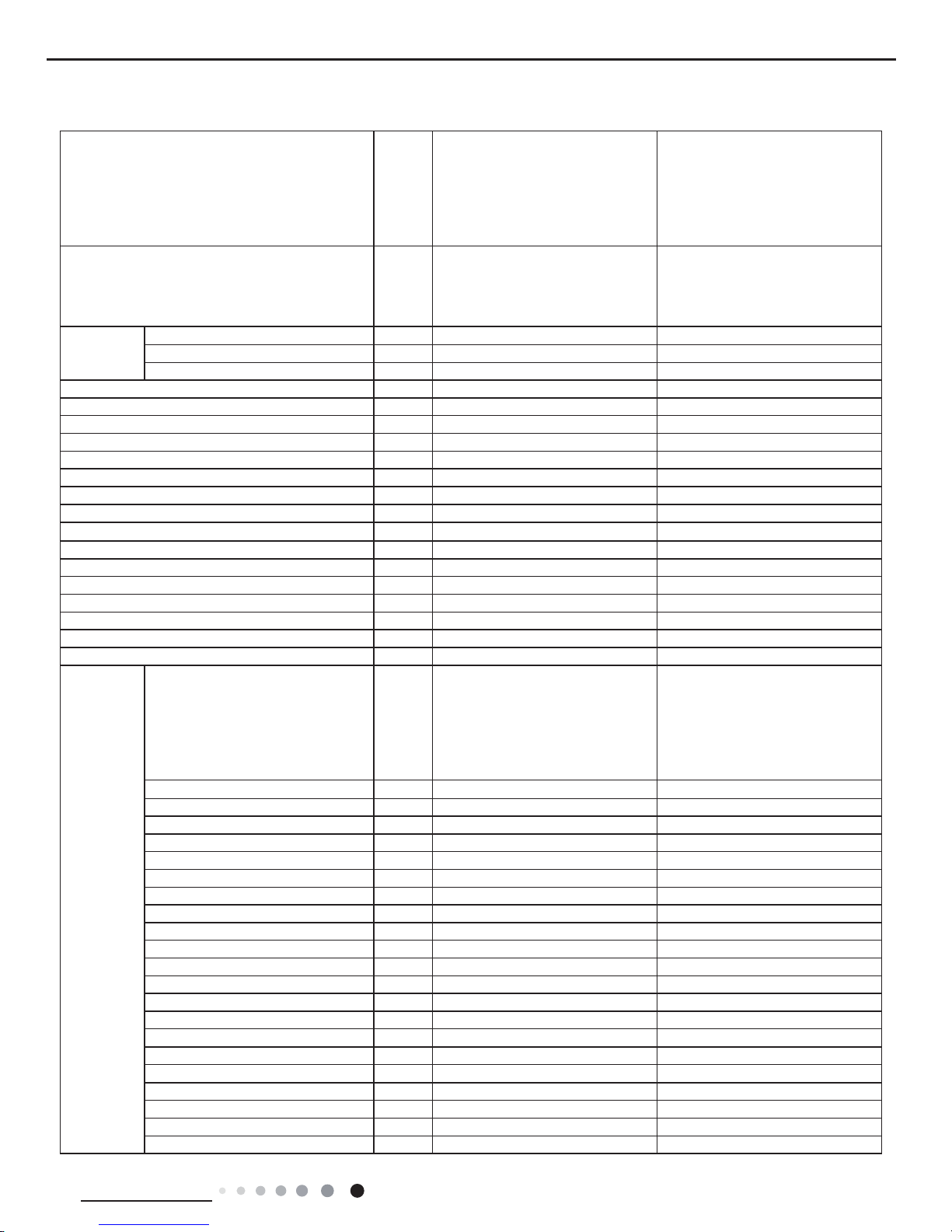
2. Specications
2.1 Specication Sheet
Model
1.GWC18QD-D3DNA6E(LC)
2.GWC18QD-D3DNB4E(LC)
3.GWC18QD-D3DNB2E(LC)
4.GWC18QD-D3DNA5E(LC)
5.GWC18QD-D3DNC2E(LC)
6.GWC18QD-D3DNB8E(LC)
7.GWC18QD-D3DNA1E(LC)
1.GWH18QD-D3DNA6E(LCLH)
2.GWH18QD-D3DNB4E(LCLH)
3.GWH18QD-D3DNB2E(LCLH)
4.GWH18QD-D3DNC2E(LCLH)
5.GWH18QD-D3DNB8E(LCLH)
6.GWH18QD-D3DNA5E(LCLH)
7.GWH18QD-D3DNA1E(LCLH)
Product Code
1.CB427001700 2.CB434001500
3.CB432002700 4.CB425004800
5.CB439000500 6.CB438001900
7.CB419007900
1.CB427002000 2.CB434001200
3.CB432002800 4.CB439000600
5.CB438001500 6.CB425004700
CB425004701 CB425004702
7.CB419008000
Power Supply
Rated Voltage V~ 208/230 208/230
Rated Frequency Hz 60 60
Phases 1 1
Power Supply Mode Outdoor Outdoor
Cooling Capacity(Min~Max) Btu/h 18000(7165~20001) 18000(7165~20001)
Heating Capacity(Min~Max) Btu/h / 19000(7336~23498)
Cooling Power Input(Min~Max) W 1800(570~2600) 1920(570~2600)
Heating Power Input(Min~Max) W / 2000(580~2600)
Cooling Power Current A 8 8.5
Heating Power Current A / 8.9
Rated Input W 2600 2600
Rated Current A 11.54 11.54
Air Flow Volume(SH/H/M/L) CFM 471/403/341/282 471/403/341/282
Dehumidifying Volume Pint/h 3.80 3.80
EER (Btu/h)/W 10.00 9.37
COP (Btu/h)/W / 9.50
SEER 16.00 16.00
HSPF / 9.00
Application Area yd
2
27.50-40.66 27.50-40.66
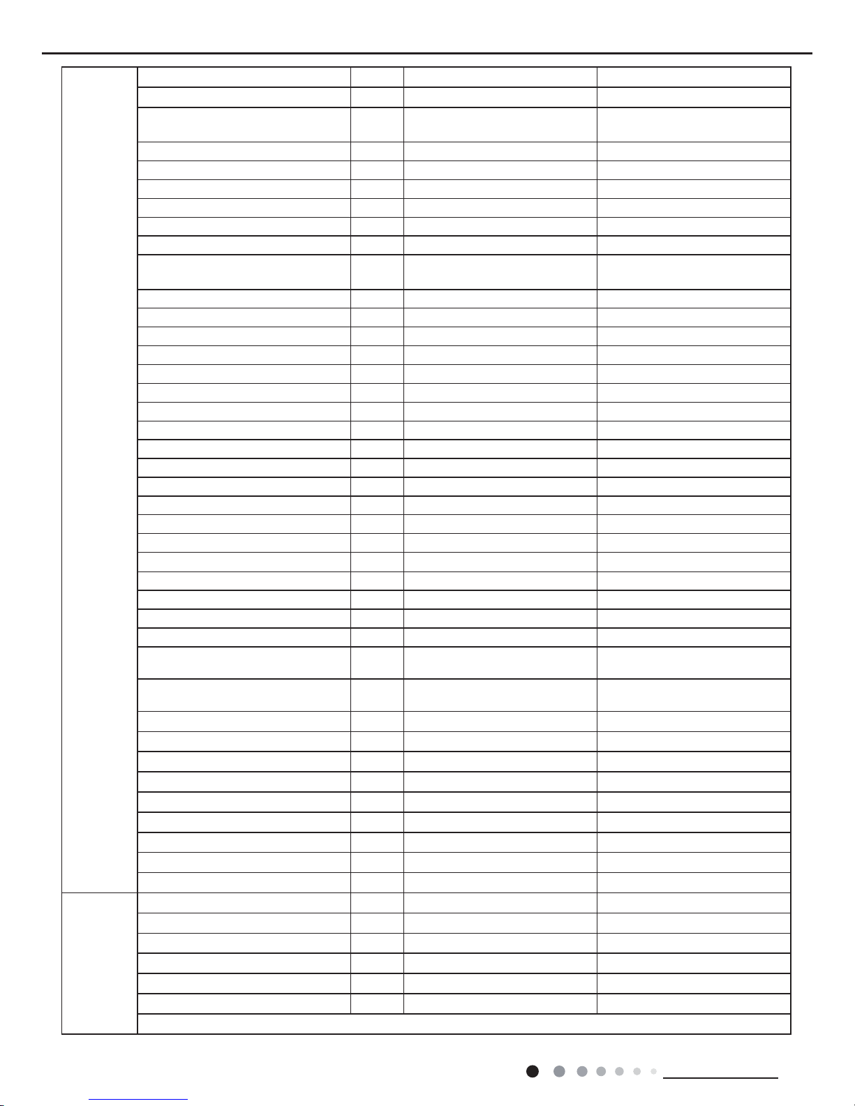
Indoor Unit
Model of indoor unit
1.GWC18QD-D3DNA6E/I
2.GWC18QD-D3DNB4E/I
3.GWC18QD-D3DNB2E/I
4.GWC18QD-D3DNA5E/I
5.GWC18QD-D3DNC2E/I
6.GWC18QD-D3DNB8E/I
7.GWC18QD-D3DNA1E/I
1.GWH18QD-D3DNA6E/I
2.GWH18QD-D3DNB4E/I
3.GWH18QD-D3DNB2E/I
4.GWH18QD-D3DNC2E/I
5.GWH18QD-D3DNB8E/I
6.GWH18QD-D3DNA5E/I
7.GWH18QD-D3DNA1E/I
Fan Type Cross-ow Cross-ow
Diameter Length(DXL) inch Φ4 3/16X27 13/16 Φ4 3/16X27 13/16
Fan Motor Cooling Speed(SH/H/M/L) r/min 1350/1200/1050/900 1350/1200/1050/900
Fan Motor Heating Speed(SH/H/M/L) r/min / 1300/1200/1100/900
Output of Fan Motor W 35 35
Fan Motor RLA A 0.37 0.37
Fan Motor Capacitor μF 2.5 2.5
Evaporator Form Aluminum Fin-copper Tube Aluminum Fin-copper Tube
Pipe Diameter inch Φ5/16 Φ5/16
Row-n Gap inch 2-1/16 2-1/16
Coil Length (LXDXW) inch 28 1/8X1X12 28 1/8X1X12
Swing Motor Model MP35CJ MP35CJ
Output of Swing Motor W 2.5 2.5
Fuse A 3.15 3.15
Sound Pressure Level(SH/H//M/L) dB (A) 46/42/39/35 46/42/39/35
Sound Power Level(SH/H//M/L) dB (A) 56/52/49/45 56/52/49/45
Dimension (WXHXD) inch 38 3/16X11 13/16X8 13/16 38 3/16X11 13/16X8 13/16
Dimension of Carton Box (LXWXH) inch 40 7/8X15X12 40 7/8X15X12
Dimension of Package (LXWXH) inch 41X15X12 5/8 41X15X12 5/8
Net Weight Ib 29.8 29.8
Gross Weight Ib 36.4 36.4
4
Technical Information
Service Manual
The above data is subject to change without notice; please refer to the nameplate of the unit.
Outdoor Unit
Model of Outdoor Unit GWC18QD-D3DNA6E/O(LC) GWH18QD-D3DNA6E/O(LCLH)
Outdoor Unit Product Code CB427W01700 CB427W02000
Compressor Manufacturer/Trademark
ZHUHAI LANDA COMPRESSOR
CO.,LTD
ZHUHAI LANDA COMPRESSOR
CO.,LTD
Compressor Model QXA-B141zF030A QXA-B141zF030A
Compressor Oil RB68EP RB68EP
Compressor Type Rotary Rotary
Compressor Locked Rotor Amp (L.R.A) A 25 25
Compressor RLA A 7.20 7.20
Compressor Power Input W 1440 1440
Overload Protector
1NT11L-6233 or KSD115OC or
HPC115/95U1
1NT11L-6233 or KSD115OC or
HPC115/95U1
Throttling Method Capillary Capillary
Operation temp ºF 60.8~86 60.8~86
Ambient temp (cooling) ºF 0~115 0~115
Ambient temp (heating) ºF / -4~75
Condenser Form Aluminum Fin-copper Tube Aluminum Fin-copper Tube
Pipe Diameter inch Φ5/16 Φ3/8
Rows-n Gap inch 1-1/16 1-1/16
Coil Length (LXDXW) inch 34 11/16X26X7/8 33 5/8X26X7/8
Fan Motor Speed rpm 800 800
Output of Fan Motor W 60 60
Fan Motor RLA A 0.365 0.365
Fan Motor Capacitor μF / /
Air Flow Volume of Outdoor Unit CFM 1883 1883
Fan Type Axial-ow Axial-ow
Fan Diameter inch Φ20 1/2 Φ20 1/2
Defrosting Method / Automatic Defrosting
Climate Type T1 T1
Isolation I I
Moisture Protection IP24 IP24
Permissible Excessive Operating
Pressure for the Discharge Side
ISPG 623 623
Permissible Excessive Operating
Pressure for the Suction Side
ISPG 362 362
Sound Pressure Level (H/M/L) dB (A) 56/-/- 56/-/-
Sound Power Level (H/M/L) dB (A) 66/-/- 66/-/-
Dimension (WXHXD) inch 38X27 9/16X15 5/8 38X27 9/16X15 5/8
Dimension of Carton Box (LXWXH) inch 40 3/8X17 7/8X29 40 3/8X17 7/8X29
Dimension of Package (LXWXH) inch 40 1/2X18X29 1/2 40 1/2X18X29 1/2
Net Weight Ib 90.4 95.9
Gross Weight Ib 100.3 105.8
Refrigerant R410A R410A
Refrigerant Charge oz 35.3 49.4
Connection
Pipe
Length ft 24.6 24.6
Gas Additional Charge oz/ft 0.2 0.2
Outer Diameter Liquid Pipe inch Φ1/4 Φ1/4
Outer Diameter Gas Pipe inch Φ1/2 Φ1/2
Max Distance Height ft 32.8 32.8
Max Distance Length ft 82 82
Note:The connection pipe applies metric diameter.
5
Technical Information
Service Manual
Model
1.GWC24QE-D3DNA6E(LC)
2.GWC24QE-D3DNB4E(LC)
3.GWC24QE-D3DNB2E(LC)
4.GWC24QE-D3DNA5E(LC)
5.GWC24QE-D3DNC2E(LC)
6.GWC24QE-D3DNB8E(LC)
7.GWC24QE-D3DNA1E(LC)
1.GWH24QE-D3DNA6E(LCLH)
2.GWH24QE-D3DNB4E(LCLH)
3.GWH24QE-D3DNB2E(LCLH)
4.GWH24QE-D3DNC2E(LCLH)
5.GWH24QE-D3DNB8E(LCLH)
6.GWH24QE-D3DNA5E(LCLH)
7.GWH24QE-D3DNA1E(LCLH)
Product Code
1.CB427002300 2.CB434001900
3.CB432003000 4.CB425004900
5.CB439000700 6.CB438001700
7.CB419007200
1.CB427002400 2.CB434001400
3.CB432002900 4.CB439001500
5.CB438001800 6.CB425005000
CB425005001 CB425005002
7.CB419007800
Power Supply
Rated Voltage V~ 208/230 208/230
Rated Frequency Hz 60 60
Phases 1 1
Power Supply Mode Outdoor Outdoor
Cooling Capacity(Min~Max) Btu/h 22000(8630~23200) 22000(8630~23200)
Heating Capacity(Min~Max) Btu/h / 23000(8650~26000)
Cooling Power Input(Min~Max) W 2260(600~27000) 2260(600~27000)
Heating Power Input(Min~Max) W / 2300(610~2750)
Cooling Power Current A 10.03 10.03
Heating Power Current A / 10.20
Rated Input W 2700 2750
Rated Current A 11.98 12.20
Air Flow Volume(SH/H/M/L) CFM 706/647/589/530 706/647/589/530
Dehumidifying Volume Pint/h 4.23 4.23
EER (Btu/h)/W 9.73 9.73
COP (Btu/h)/W / 10.00
SEER 16.00 16.00
HSPF / 9.00
Application Area yd
2
32.29-50.23 32.29-50.23
Indoor Unit
Model of indoor unit
1.GWC24QE-D3DNA6E/I
2.GWC24QE-D3DNB4E/I
3.GWC24QE-D3DNB2E/I
4.GWC24QE-D3DNA5E/I
5.GWC24QE-D3DNC2E/I
6.GWC24QE-D3DNB8E/I
7.GWC24QE-D3DNA1E/I
1.GWH24QE-D3DNA6E/I
2.GWH24QE-D3DNB4E/I
3.GWH24QE-D3DNB2E/I
4.GWH24QE-D3DNC2E/I
5.GWH24QE-D3DNB8E/I
6.GWH24QE-D3DNA5E/I
7.GWH24QE-D3DNA1E/I
Fan Type Cross-ow Cross-ow
Diameter Length(DXL) inch Φ4 1/4X32 11/16 Φ4 1/4X32 11/16
Fan Motor Cooling Speed(SH/H/M/L) r/min 1250/1100/900/800 1250/1100/900/800
Fan Motor Heating Speed(SH/H/M/L) r/min / 1150/1000/900/850
Output of Fan Motor W 30 30
Fan Motor RLA A 0.32 0.32
Fan Motor Capacitor μF 3 3
Evaporator Form Aluminum Fin-copper Tube Aluminum Fin-copper Tube
Pipe Diameter inch Φ5/16 Φ5/16
Row-n Gap inch 2-1/16 2-1/16
Coil Length (LXDXW) inch 33 1/4X1X13 1/2 33 1/4X1X13 1/2
Swing Motor Model MP35CJ MP35CJ
Output of Swing Motor W 2.5 2.5
Fuse A 3.15 3.15
Sound Pressure Level(SH/H//M/L) dB (A) 48/44/40/36 48/44/40/36
Sound Power Level(SH/H//M/L) dB (A) 58/54/50/46 58/54/50/46
Dimension (WXHXD) inch 42 7/16X12 13/16X9 11/16 42 7/16X12 13/16X9 11/16
Dimension of Carton Box (LXWXH) inch 45X16 1/8X13 3/16 45X16 1/8X13 3/16
Dimension of Package (LXWXH) inch 45 3/16X16 1/4X13 3/4 45 3/16X16 1/4X13 3/4
Net Weight Ib 34.2 37.5
Gross Weight Ib 41.9 45.2
6
Technical Information
Service Manual
Outdoor Unit
Model of Outdoor Unit GWC24QE-D3DNA6E/O(LC) GWH24QE-D3DNA6E/O(LCLH)
Outdoor Unit Product Code CB427W02300 CB427W02400
Compressor Manufacturer/Trademark
ZHUHAI LANDA COMPRESSOR
CO.,LTD
ZHUHAI LANDA COMPRESSOR
CO.,LTD
Compressor Model QXA-B141zF030A QXA-B141zF030A
Compressor Oil 68EP 68EP
Compressor Type Rotary Rotary
Compressor Locked Rotor Amp (L.R.A) A 25.00 25.00
Compressor RLA A 7.20 7.20
Compressor Power Input W 1440 1440
Overload Protector
1NT11L-6233 or KSD115℃ or
HPC115/95U1
1NT11L-6233 or KSD115℃ or
HPC115/95U1
Throttling Method Capillary Capillary
Operation temp ºF 60.8~86 60.8~86
Ambient temp (cooling) ºF 0~115 0~115
Ambient temp (heating) ºF / -4~75
Condenser Form Aluminum Fin-copper Tube Aluminum Fin-copper Tube
Pipe Diameter inch Φ3/8 Φ3/8
Rows-n Gap inch 2-1/16 2-1/16
Coil Length (LXDXW) inch 33 5/16X1 3/4X26 33 5/16X1 3/4X26
Fan Motor Speed rpm 800 800
Output of Fan Motor W 60 60
Fan Motor RLA A 0.365 0.365
Fan Motor Capacitor μF / /
Air Flow Volume of Outdoor Unit CFM 1883 1883
Fan Type Axial-ow Axial-ow
Fan Diameter inch Φ20 1/2 Φ20 1/2
Defrosting Method / Automatic Defrosting
Climate Type T1 T1
Isolation I I
Moisture Protection IP24 IP24
Permissible Excessive Operating
Pressure for the Discharge Side
ISPG 623 623
Permissible Excessive Operating
Pressure for the Suction Side
ISPG 362 362
Sound Pressure Level (H/M/L) dB (A) 59/-/- 59/-/-
Sound Power Level (H/M/L) dB (A) 69/-/- 69/-/-
Dimension (WXHXD) inch 38X27 9/16X15 5/8 38X27 9/16X15 5/8
Dimension of Carton Box (LXWXH) inch 40 3/8X17 7/8X29 40 3/8X17 7/8X29
Dimension of Package (LXWXH) inch 40 1/2X18X29 1/2 40 1/2X18X29 1/2
Net Weight Ib 103.6 110.3
Gross Weight Ib 113.6 120.2
Refrigerant R410A R410A
Refrigerant Charge oz 56.45 65.25
Connection
Pipe
Length ft 24.6 24.6
Gas Additional Charge oz/ft 0.5 0.2
Outer Diameter Liquid Pipe inch Φ1/4 Φ1/4
Outer Diameter Gas Pipe inch Φ5/8 Φ5/8
Max Distance Height ft 32.8 32.8
Max Distance Length ft 82 82
Note:The connection pipe applies metric diameter.
The above data is subject to change without notice; please refer to the nameplate of the unit.
7
Technical Information
Service Manual
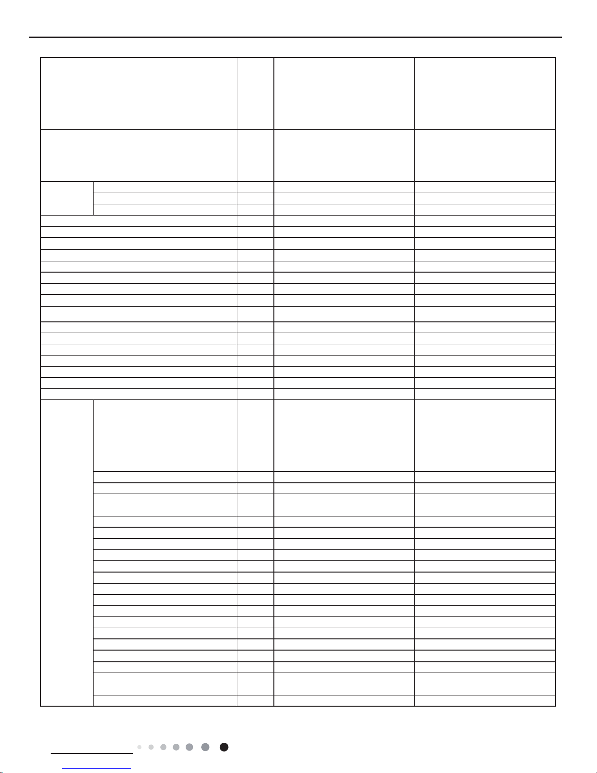
2.2 Operation Characteristic Curve
01020304050607090010 20 30 40 50 60 70 80 90 100 120110
80
11
10
9
8
7
6
5
4
3
2
1
0
Compressor speed (rps)
)A(tnerruC
11
10
9
8
7
6
5
4
3
2
1
0
Compressor speed (rps)
)A(tnerruC
CoolingHeating
24K
24K
18K
18K
Conditions
Indoor:DB80°F/WB66.9°F
Outdoor:DB95°F
Indoor air flow:Super High
Pipe length:24.6ft
Conditions
Indoor:DB70°F/WB60°F
Outdoor:DB19.94°F/WB19.04°F
Indoor air flow:Super High
Pipe length:24.6ft
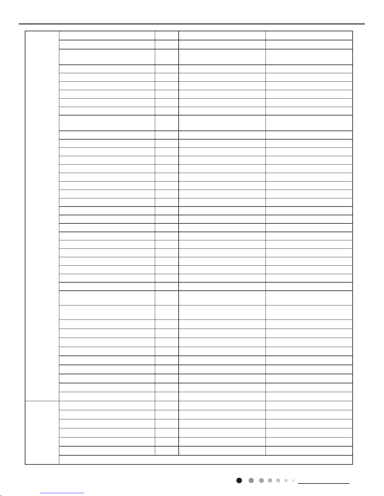
2.3 Capacity Variation Ratio According to Temperature
Cooling
Cooling
Heating
Heating
-4 514
110
100
90
80
70
60
50
40
23 32 41 50
Outdoor temp.(°F)
Capacity ratio (%)
89.6 91.4 93.295 96.8 98.6 100.4 102.2
109.4
104
105.8 107.6
100
105
95
90
85
80
75
70
65
60
55
50
Outdoor temp.(°F)
Capacity ratio (%)
Conditions
Indoor:DB
80°F
/WB66.9
°F
Outdoor:DB95°F
Indoor air flow:Super High
Pipe length:
24.6ft
Conditions
Indoor:DB
70°F
Outdoor:DB19.94°F/WB19.04°F
Indoor air flow:Super High
Pipe length:
24.6ft
8
Technical Information
Service Manual
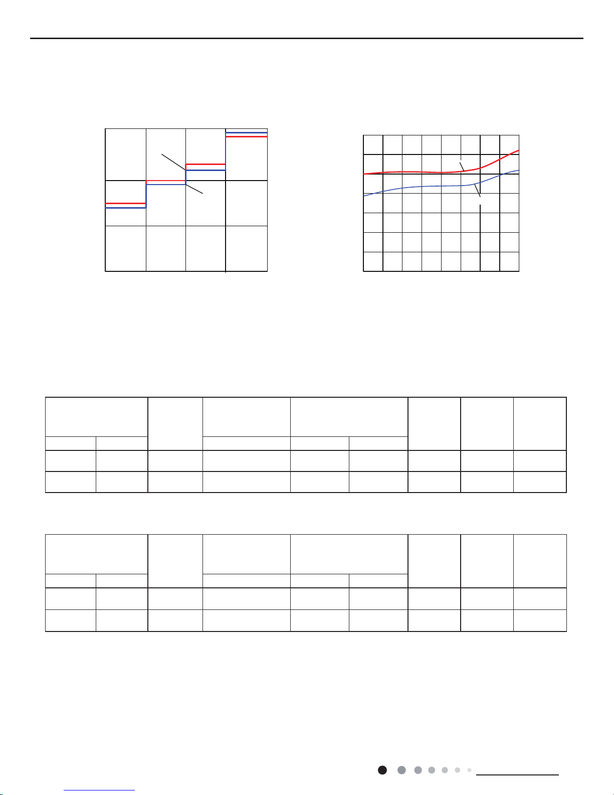
2.5 Cooling and Heating Data Sheet in Rated Frequency
Rated cooling
condition(°F) (DB/WB)
Model
Pressure of gas pipe
connecting indoor and
outdoor unit
Inlet and outlet pipe
temperature of heat
exchanger
Fan speed of
indoor unit
Fan speed of
outdoor unit
Compressor
revolution
(rps)
Indoor Outdoor P (PSIG) T1 (°F) T2 (°F)
80/66.9 95/- 18K 130~142
in:46.4~51.8
out:51.8~57.2
in:167~181.4
out:98.6~118.4
Super High High 73
80/66.9 95/- 24K 130~142
in:46.4~51.8
out:51.8~57.2
in:167~181.4
out:98.6~118.4
Super High High 75
Rated heating
condition(°F) (DB/WB)
Model
Pressure of gas pipe
connecting indoor and
outdoor unit
Inlet and outlet pipe
temperature of heat
exchanger
Fan speed of
indoor unit
Fan speed of
outdoor unit
Compressor
revolution
(rps)
Indoor Outdoor P (PSIG) T1 (°F) T2 (°F)
70/60 19.94/19.04 18K 507~550
in:167~181.4
out:98.6~113
in:33.8~37.4
out:35.6~42.8
Super High High 75
70/60 19.94/19.04 24K 507~550
in:167~181.4
out:98.6~113
in:33.8~37.4
out:35.6~42.8
Super High High 80
Instruction:
T1: Inlet and outlet pipe temperature of evaporator
T2: Inlet and outlet pipe temperature of condenser
P: Pressure at the side of big valve
Connection pipe length: 24.6ft.
Cooling:
Heating:
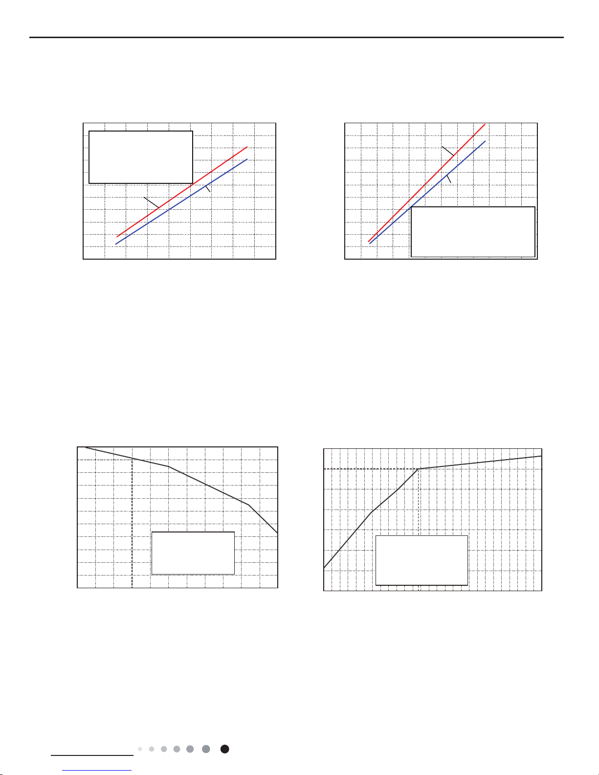
2.4 Noise Curve
24K
18K
20
30
40
50
LM HSH
Indoor fan motor rating speed
Noise/dB(A)
46
48
50
52
54
56
58
60
20 30 40 50 60 70 80 90
100
Compressor frequency(Hz)
Noise dB(A)
Heating
Cooling
Indoor side noise Outdoor side noise
9
Technical Information
Service Manual
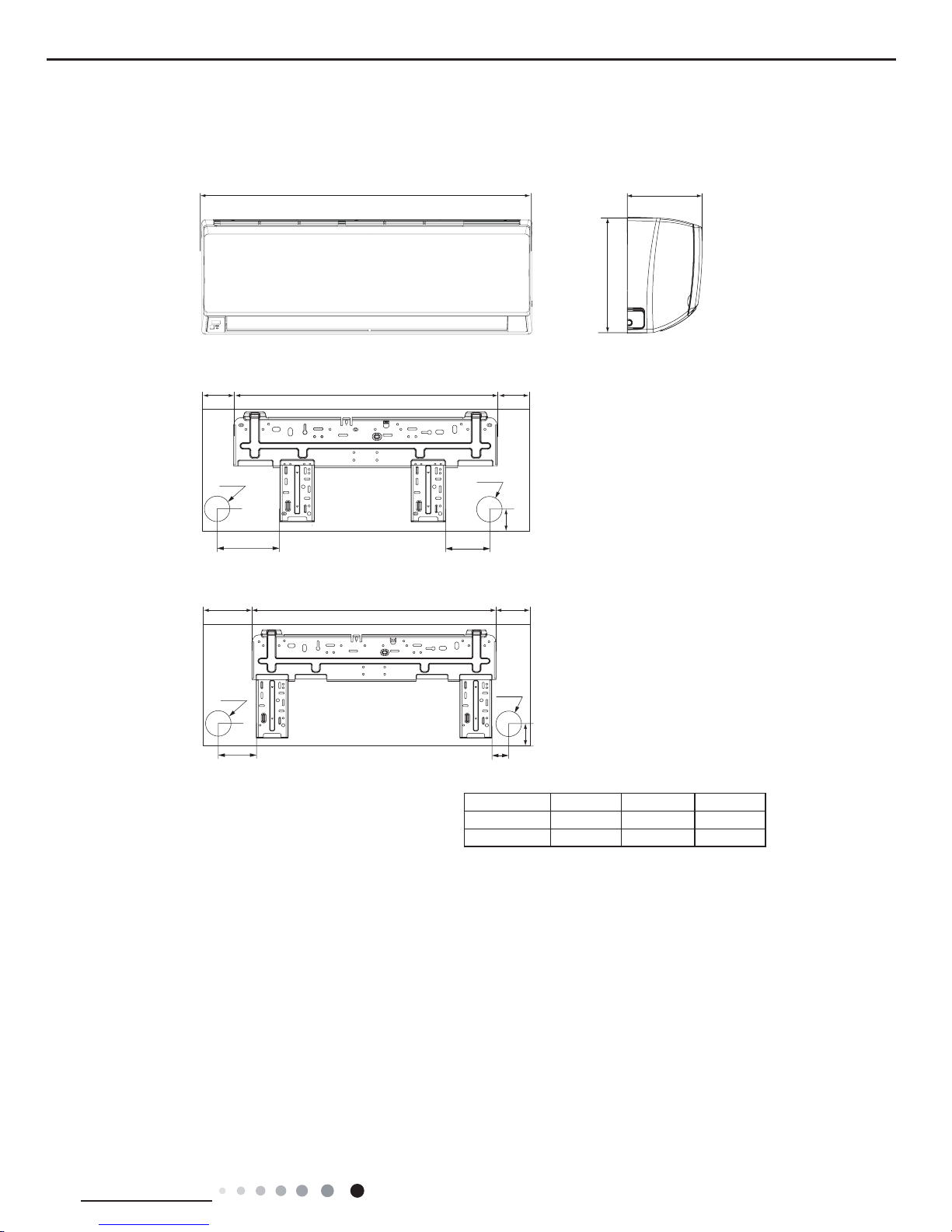
3. Outline Dimension Diagram
3.1 Indoor Unit
W
D
H
4277 3/16
5 1/2
7 1/2
1 1/2
Φ2 3/16
Φ2 3/16
3 1/8
6
1 11/16
8 1/8 27 7 5/16
Φ2 3/4
Φ2 3/4
Unit:inch
18K
24K
Models W H D
18K 38 3/16 11 13/16 8 13/16
24K 42 7/16 12 13/16 9 11/16
10
Technical Information
Service Manual
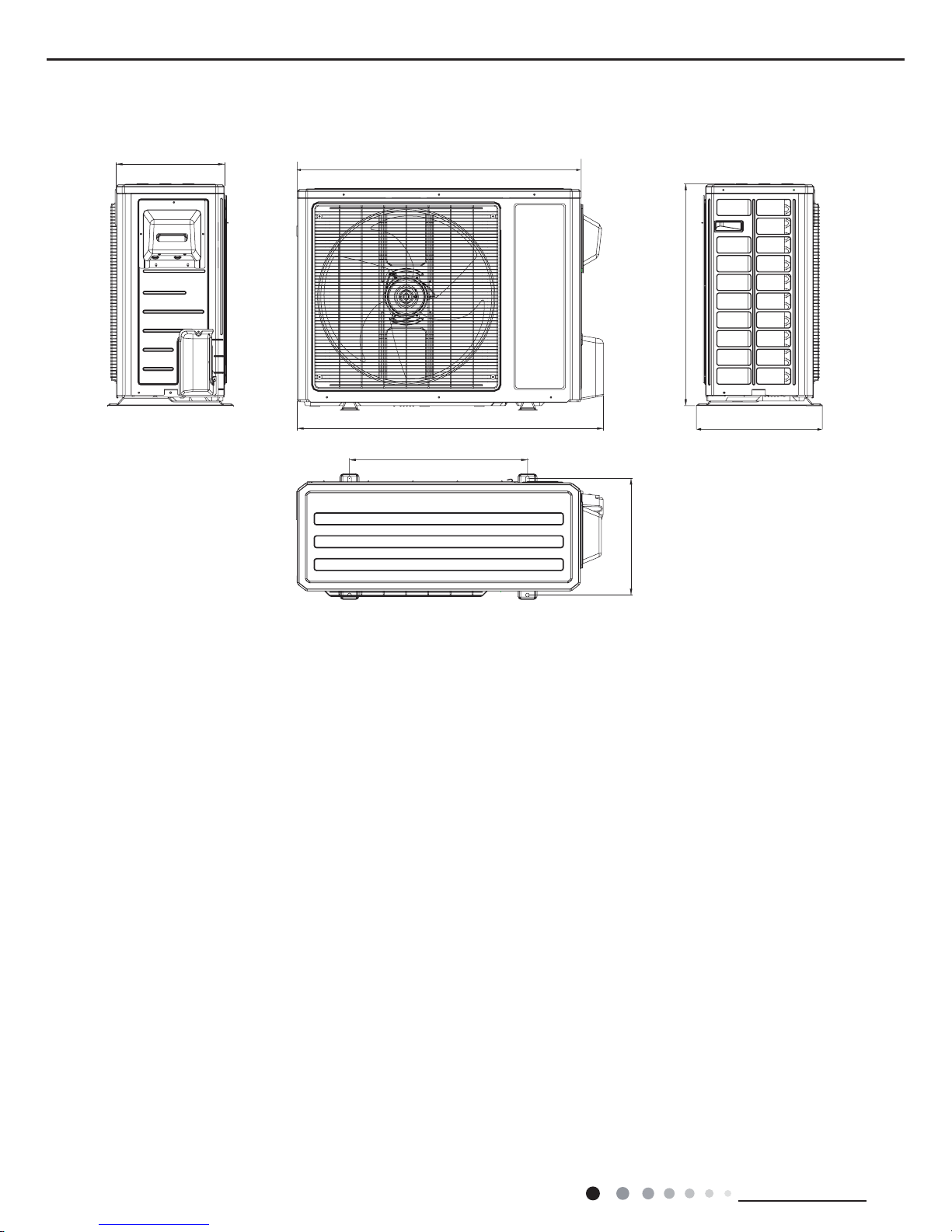
3.2 Outdoor Unit
Unit: inch
35
13 3/8
27 9/16
15 5/8
38
14 5/16
22
11
Technical Information
Service Manual
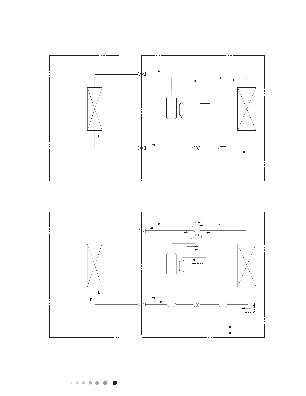
4. Refrigerant System Diagram
Connection pipe specication:
Liquid pipe:1/4"inch
Gas pipe:1/2"(for 18K)
Gas pipe:5/8"(for 24K)
Indoor unit
Outdoor unit
Indoor unit
Outdoor unit
COOLING
HEATING
Accumlator
4-Way valve
Discharge
Suction
Discharge
Suction
Heat
exchanger
(evaporator)
Heat
exchanger
(evaporator)
Heat
exchanger
(condenser)
Heat
exchanger
(condenser)
Valve
Valve
Valve
Valve
Liquid pipe
side
Gas pipe
side
Liquid pipe
side
Gas pipe
side
Strainer
Strainer Strainer
Capillary
Capillary
Compressor
Compressor
Accumlator
Cooling only models
Cooling and heating models
12
Technical Information
Service Manual
5. Electrical Part
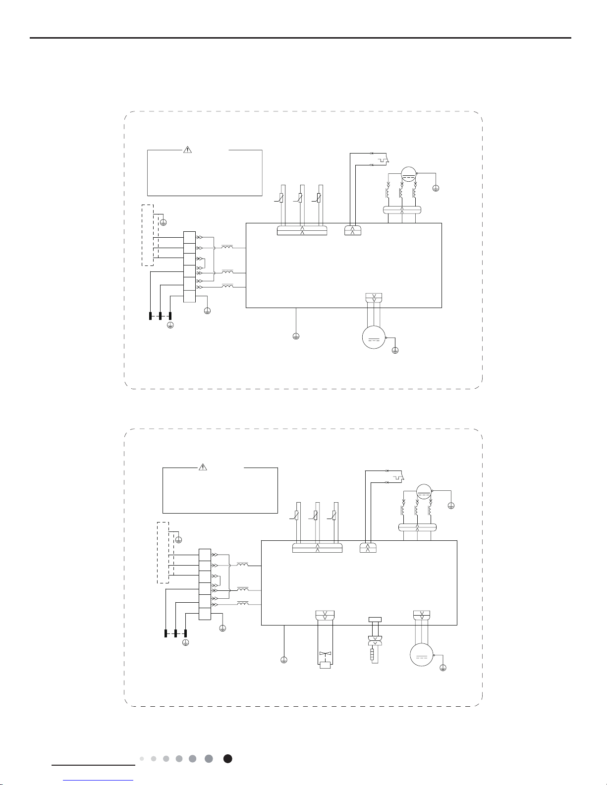
5.1 Wiring Diagram
● Indoor Unit
● Instruction
Symbol Symbol Color Symbol Symbol Color Symbol Name
WH White GN Green CAP Jumper cap
YE Yellow BN Brown COMP Compressor
RD Red BU Blue Grounding wire
YEGN Yellow/Green BK Black / /
VT Violet OG Orange / /
Note: Jumper cap is used to determine fan speed and the swing angle of horizontal lover for this model.
STEPPING
CAP
BLOCK
TERMINAL
G
EVAPORATOR
JUMP
AP2: MAIN BOARD
YEGN
BK
BN
YEGN
N1
2
N(1)
XT1
BU
AC-L
COM-OUT
COM-MANUAL
CONNECTOR
AP3
WIRED
MOTOR
OUTDOOR UNIT
T-SENSOR DISP2DISP1
RT1
θ
AP1
ROOM
TUBE
TEMP.SENSOR
TEMP.SENSOR
DISPLAY BOARD
RECEIVER AND
θ
RT2
SWING-UD
M2
ELECTRIC BOX
G
CONTROLLER
WH(BU)
BK
RD(BN)
GN(YEGN)
3
63610000441
PGFPG
FAN
MOTOR
M1
13
Technical Information
Service Manual
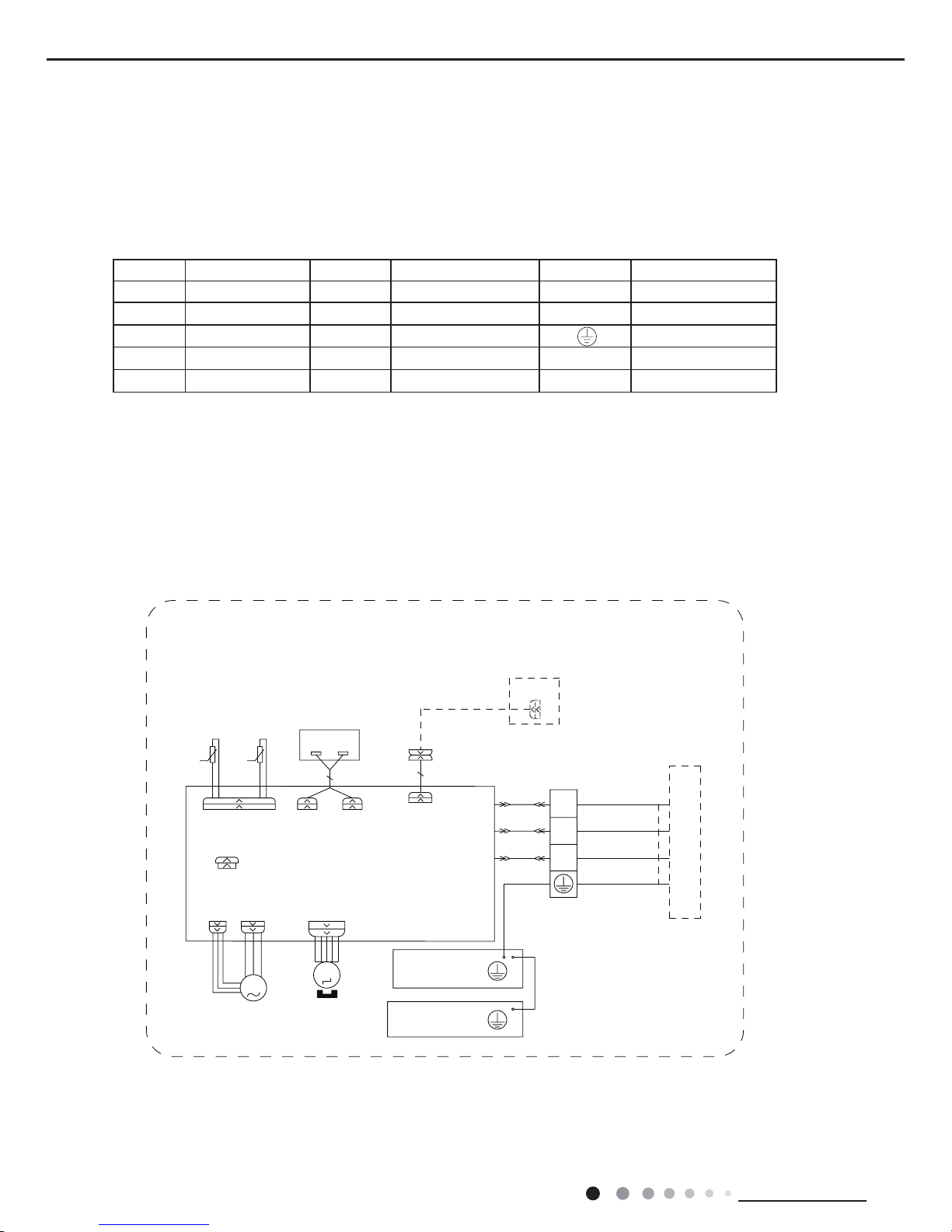
● Outdoor Unit
GWC18QD-D3DNA6E/O GWC24QE-D3DNA6E/O
$3
7(036(1625
(;+$867
7(036(1625
2875220
28778%(
7(036(1625
%.
:+
%8
<(
;
&203
6$7
:+ :+
29&B&203
5'
575757
*
*
5'
%8 <(
8%89<( :5'
<(*1
7B6(1625
29(5/2$'3527(&725
/
0$*1(7,&
5,1*
/
/
$&B/
1
&20B,11(5
3(
<(*1
*
/ /
*1<(*1
:+%8
*
/
/
1
5'%1
%.
:+%8
;7
,1'22581,7
/
5,1*
%.
%1
%8
%1
%8
*1<(*1
%/2&.
7(50,1$/
*
0$*1(7,&
*
0
2)$1
)$102725
<(*1
*
/
35,17('&,5&8,7%2$5'
89 :
/
&203
32:(5
3OHDVHGRQWWRXFKDQ\WHUPLQDO
ZKHQWKHYROWDJHRIWHUPLQDO
3'&DQG1'&DW$3LV
KLJKHUWKDQ9WRSUHYHQWWKH
ULVNRIHOHFWULFVKRFN
:$51,1*
%.%1
. . .
*
<(*1
63610000446
The above data is subject to change without notice. Please refer to the nameplate of the unit.
GWH18QD-D3DNA6E/O GWH24QE-D3DNA6E/O
5'
%$1'
+($7(5
%27720
5'
(+
+($7B%
*
...
%.%1
:$51,1*
3OHDVHGRQWWRXFKDQ\WHUPLQDO
ZKHQWKHYROWDJHRIWHUPLQDO
3'&DQG1'&DW$3LV
KLJKHUWKDQ9WRSUHYHQWWKH
ULVNRIHOHFWULFVKRFN
32:(5
&203
/
:98
35,17('&,5&8,7%2$5'
/
*
<(*1
)$102725
:$< 2)$1
7979
9$/9(
<9
:$<
0
*
0$*1(7,&
*
7(50,1$/
%/2&.
*1<(*1
%8
%1
%8
%1
%.
5,1*
/
,1'22581,7
;7
:+%8
%.
5'%1
1
/
/
*
:+%8
*1<(*1
/
/
*
<(*1
3(
&20B,11(5
1
$&B/
/
/
5,1*
0$*1(7,&
/
29(5/2$'3527(&725
7B6(1625
<(*1
:5'9<(8%8
8%(<
5'
*
*
57 57 57
5'
29&B&203
+:+:
6$7
&203
;
<(
%8
:+
%.
7(036(1625
28778%(
2875220
7(036(1625
(;+$867
7(036(1625
$3
<(*1
14
Technical Information
Service Manual
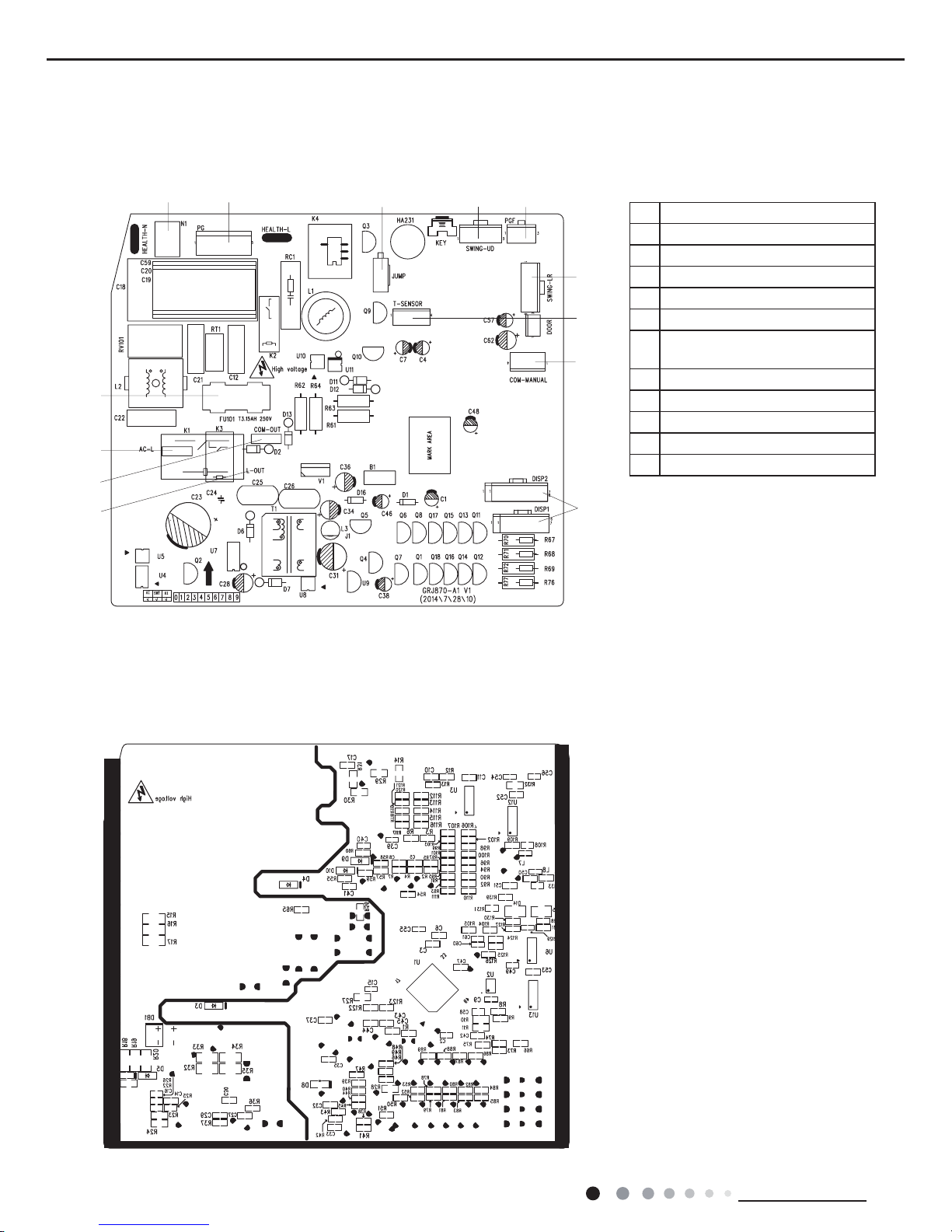
5.2 PCB Printed Diagram
● Top view
● Bottom view
Indoor Unit
1 Neutral wire
2 Motor of indoor fan
3 Jumper cap
4 Up&down swing motor
5 Feedback interface of indoor fan
6 Interface of temperature sensor
7
Interface of wired controller(only for
the mode with this function)
8 Display interface
9 Control port of compressor
10 Interface of communication circuit
11 Live wire
12 Fuse
12 34
5
6
7
8
9
10
11
12
15
Technical Information
Service Manual
4568911
12
13
14
15
16
17
18
19
123710
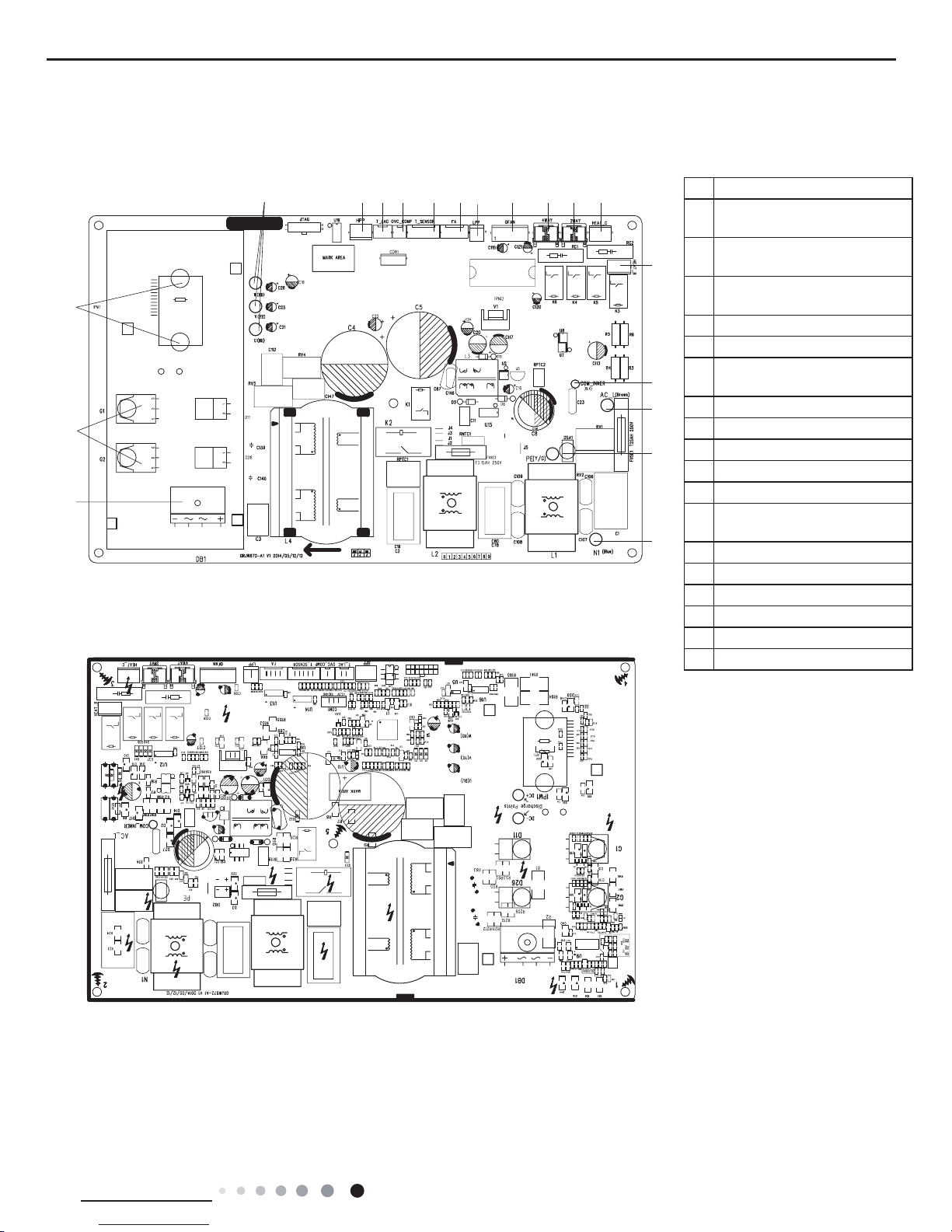
● Top view
● Bottom view
Outdoor Unit
1 Interface of compressor
2
High pressure protection of
system
3
Low-temperature cooling
temperature sensor
4
Overload protection of
compressor
5 Interface of temperature sensor
6 Electronic expansion valve
7
Low pressure protection of
system
8 Interface of fan
9 Interface of 4-way valve
10 Interface of 2-way valve
11 Electric heating belt of chassis
12 lectric heating belt of chassis
13
Communication interface for
indoor unit and outdoor unit
14 Live wire
15 Earthing wire
16 Neutral wire
17 Rectier
18 IGBT
19 IPM1
16
Technical Information
Service Manual
6. Function and Control
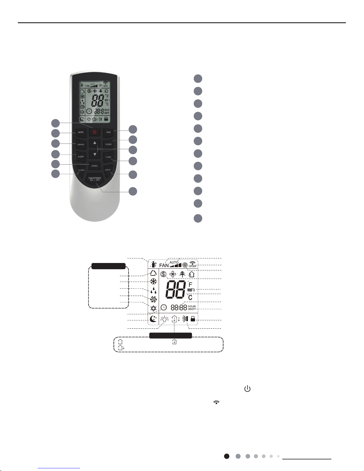
6.1 Remote Controller Introduction
Introduction for icons on display screen
Introduction for buttons on remote controller
1
5
3
6
8
10
12
11
9
7
4
2
1
2
3
4
5
6
7
8
9
10
11
12
ON/OFF button
MODE button
FAN button
SWING button
TURBO button
TEMP button
I FEEL button
LIGHT button
CLOCK button
TIMER ON / TIMER OFF
button
SLEEP button
▲/ button
▲
Send signal
Turbo mode
8ć heating function
Set temperature
WiFi(This unit is without WiFi function)
Set time
TIMER ON / TIMER OFF
Child lock
Up & down swing
Set fan speed
Light
Temp. display type
:Set temp.
:Outdoor ambient temp.
:Indoor ambient temp.
Sleep mode
Clock
Heat mode
Fan mode
Dry mode
Cool mode
Auto mode
Operation mode
I feel
Note:
● After putting through the power, the air conditioner will give out a sound. Operation indictor "
" is ON (red indicator). After that,
you can operate the air conditioner by using remote controller.
●
Under ON status, pressing the button on the remote controller, the signal icon " "
on the display of remote controller will blink once
and the air conditioner will give out a “de” sound, which means the signal has been sent to the air conditioner.
● Under OFF status, set temperature and clock icon will be displayed on the display of remote controller (If timer ON, timer OFF
and
light functions are set, the corresponding icons will be displayed on the display of remote controller at the same
time); Under ON
status, the display will show the corresponding set function icons.
17
Technical Information
Service Manual
1. ON/OFF button
2. MODE button
3. FAN button
Press this button can turn on or turn off the air conditioner. After turning on the air conditioner, operation indicator " "on indoor unit’s
display is ON (green indicator. The colour is different for different models), and indoor unit will give out a sound.
● When selecting auto mode, air conditioner will operate automatically according to factory setting. Set temperature can’t be adjusted and
will not be displayed as well. Press "FAN" button can adjust fan speed. Press "SWING" button can adjust fan blowing angle.
● After selecting cool mode, air conditioner will operate under cool mode. Cool indicator " "on indoor unit is ON. Press "▲" or " ▲ " button
to adjust set temperature. Press "FAN" button to adjust fan speed. Press "SWING" button to adjust fan blowing angle.
● When selecting dry mode, the air conditioner operates at low speed under dry mode. Dry indicator " " on indoor unit is ON. Under dry
mode, fan speed can’t be adjusted. Press "SWING" button to adjust fan blowing angle.
● When selecting fan mode, the air conditioner will only blow fan, no cooling and no heating. All indicators are OFF. Press "FAN" button to
adjust fan speed. Press "SWING" button to adjust fan blowing angle.
● When selecting heating mode, the air conditioner operates under heat mode. Heat indicator " " on indoor unit is ON. Press "▲" or " ▲ "
button to adjust set temperature. Press "FAN" button to adjust fan speed. Press "SWING" button to adjust fan blowing angle. (Cooling only
unit won’t receive heating mode signal. If setting heat mode with remote controller, press ON/OFF button can’t start up the unit).
Note:
● For preventing cold air, after starting up heating mode, indoor unit will delay 1~5 minutes to blow air (actual delay time is depend on indoor
ambient temperature).
● Set temperature range from remote controller: 16~30℃ (60.8~86.0OF); Fan speed: auto, low speed, medium speed, high speed.
5. TURBO button
Under COOL or HEAT mode, press this button to turn to quick COOL or quick HEAT mode. " " icon is displayed on remote controller.
Press this button again to exit turbo function and " " icon will disappear.
6. ▲/▲ button
● Press "▲" or "▲" button once increase or decrease set temperature 1OC(1OF). Holding "▲" or "▲" button, 2s later, set temperature
on remote controller will change quickly. On releasing button after setting is finished, temperature indicator on indoor unit will change
accordingly. (Temperature can’t be adjusted under auto mode)
● When setting TIMER ON, TIMER OFF or CLOCK, press "▲" or "▲" button to adjust time. (Refer to CLOCK, TIMER ON, TIMER OFF
buttons) When setting TIMER ON, TIMER OFF or CLOCK, press "▲" or "▲" button to adjust time. (Refer to CLOCK, TIMER ON, TIMER
OFF buttons)
Caution:
● Under AUTO speed, air conditioner will select proper fan speed automatically according to factory setting.
● Fan speed under dry mode is low speed.
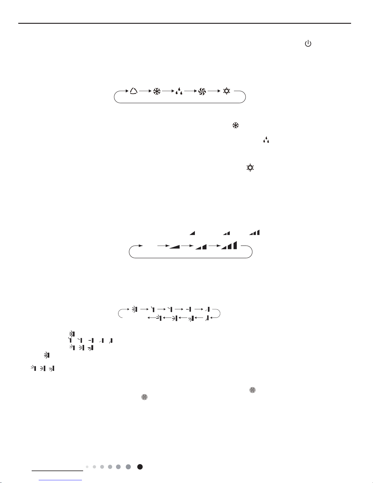
Pressing this button can set fan speed circularly as: auto (AUTO), low( ) ,medium( ), high( ).
Press this button to select your required operation mode.
AUTO COOL FA N
DRY HEAT
Auto
4. SWING button
Press this button can select up&down swing angle. Fan blow angle can be selected circularly as below:
● When selecting " ", air conditioner is blowing fan automatically. Horizontal louver will automatically swing up & down at maximum angle.
● When selecting " 、 、 、 、 ", air conditioner is blowing fan at xed position. Horizontal louver will stop at the xed position.
● When selecting " 、 、 " , air conditioner is blowing fan at xed angle. Horizontal louver will send air at the xed angle.
● Hold " "button above 2s to set your required swing angle. When reaching your required angle, release the button.
Note:
● " 、 、 " may not be available. When air conditioner receives this signal, the air conditioner will blow fan automatically.
no display
(horizontal louvers stops at current position)

18
Technical Information
Service Manual
7. SLEEP button
9. I FEEL button
10. LIGHT button
11. CLOCK button
12. TIMER ON / TIMER OFF button
Under COOL, HEAT or DRY mode, press this button to start up sleep function. " " icon is displayed on remote controller. Press this button
again to cancel sleep function and " " icon will disappear.
Press this button to start I FEEL function and " " will be displayed on the remote controller. After this function is set, the remote controller
will send the detected ambient temperature to the controller and the unit will automatically adjust the indoor temperature according to the
detected temperature. Press this button again to close I FEEL function and " " will disappear.
● Please put the remote controller near user when this function is set. Do not put the remote controller near the object of high temperature
or low temperature in order to avoid detecting inaccurate ambient temperature.
Press this button to turn off display light on indoor unit. " " icon on remote controller disappears. Press this button again to turn on
display light. " " icon is displayed.
Press this button to set clock time. " " icon on remote controller will blink. Press "▲" or "▲" button within 5s to set clock time. Each
pressing of "▲" or "▲" button, clock time will increase or decrease 1 minute. If hold "▲" or "▲" button, 2s later, time will change quickly.
Release this button when reaching your required time. Press "CLOCK" button to conrm the time. " " icon stops blinking.
Note:
● Clock time adopts 24-hour mode.
● The interval between two operation can’t exceeds 5s. Otherwise, remote controller will quit setting status. Operation for TIMER ON/TIMER
OFF is the same.
● TIMER ON button
"TIMER ON" button can set the time for timer on. After pressing this button, " " icon disappears and the word "ON" on remote controller
blinks. Press "▲" or "▲"button to adjust TIMER ON setting. After each pressing "▲" or "▲" button, TIMER ON setting will increase or
decrease 1min. Hold "▲" or "▲" button, 2s later, the time will change quickly until reaching your required time. Press "TIMER ON" to
conrm it. The word "ON" will stop blinking. " " icon resumes displaying. Cancel TIMER ON: Under the condition that TIMER ON is
started up, press "TIMER ON" button to cancel it.
● TIMER OFF button
"TIMER OFF" button can set the time for timer off. After pressing this button," " icon disappears and the word "OFF" on remote
controller blinks. Press "▲" or "▲" button to adjust TIMER OFF setting. After each pressing "▲" or "▲" button,
TIMER OFF setting will increase or decrease 1min. Hold "▲" or "▲" button, 2s later, the time will change quickly until reaching your
required time. Press "TIMER OFF" word "OFF" will stop blinking. " " icon resumes displaying. Cancel TIMER OFF. Under the condition
that TIMER OFF is started up, press "TIMER OFF" button to cancel it.
Note:
● Under on and off status, you can set TIMER OFF or TIMER ON simultaneously.
● Before setting TIMER ON or TIMER OFF, please adjust the clock time.
● After starting up TIMER ON or TIMER OFF, set the constant circulating valid. After that, air conditioner will be turned on or turned off
according to setting time. ON/OFF button has no effect on setting. If you don’t need this function, please use remote controller to cancel it.
8. TEMP button
By pressing this button, you can see indoor set temperature, indoor ambient temperature or outdoor ambient temperature on indoor unit’s
display. The setting on remote controller is selected circularly as below:
● When selecting " " or no display with remote controller, temperature indicator on indoor unit displays set temperature.
● When selecting " " with remote controller, temperature indicator on indoor unit displays indoor ambient temperature.
● When selecting " " with remote controller, temperature indicator on indoor unit displays outdoor ambient temperature.
Note:
●
Outdoor temperature display is not available for some models. At that time, indoor
unit receives " "signal, while it displays indoor set
temperature.
● It’s defaulted to display set temperature when turning on the unit.There is no display in the remote controller.
● Only for the models whose indoor unit has dual-8 display.
● When selecting displaying of indoor or outdoor ambient temperature, indoor temperature indicator displays corresponding temperature and
automatically turn to display set temperature after three or ve seconds.
no display
19
Technical Information
Service Manual
Function introduction for combination buttons
Operation guide
Replacement of batteries in remote controller
1. Energy-saving function
1.
After putting through the power, press "ON/OFF" button on remote controller to turn on the air conditioner.
2. Press "MODE" button to select your required mode:
AUTO, COOL, DRY, FA N, HEAT.
3. Press "▲" or "
▲
" button to set your required temperature. (Temperature can’t be adjusted under auto mode).
4. Press "F
AN" button to set your required fan speed: auto, low, medium and high speed.
5. Press "SWING" button to select fan blowing angle.
● During operation, point the remote control signal sender at the receiving window on indoor unit.
●
The distance between signal sender and receiving window should be no more than 8m, and there should be no obstacles between them.
indoor unit during operation.
● Replace new batteries of the same model when replacement is required.
● When you don’t use remote controller for a long time, please take out the batteries
.
● If the display on remote controller is fuzzy or there’s no display, please replace batteries.
2. 8
ć
heating function
3. Child lock function
4. T
emperature display switchover function
5.
About WIFI function(This unit is without WiFi function)
Under cooling mode, press "TEMP" and " CLOCK" buttons simultaneously to start up or turn off energy-saving function. When energy-saving
function is started up, "SE" will be shown on remote controller, and air conditioner will adjust the set temperature automatically
according
to factory setting to reach to the best energy-saving effect. Press "TEMP" and "CLOCK"buttons simultaneously again to exit energy-saving
function.
Note:
● Under energy-saving function, fan speed is defaulted at auto speed and it can’t be adjusted.
●
Under energy-saving function, set temperature can’t be adjusted. Press "TURBO"
button and the remote controller won’t send signal.
● Sleep function and energy-saving function can’t operate at the same time. If energy-saving function has been set under cooling mode,
press sleep button will cancel energy-saving function. If sleep function has been set under cooling mode, start up the energy-saving
function will cancel sleep function.
Under heating mode, press "TEMP" and "CLOCK" buttons simultaneously to start
up or turn off 8ć heating function. When this function
is
started up, "
" and "8ć" will be shown on remote controller, and the air conditioner keep the heating status
at 8ć. Press "TEMP"
and
"CLOCK" buttons simultaneously again to exit 8ćheating function.
Note:
● Under 8ć heating function, fan speed is defaulted at auto speed and it can’t be adjusted.
● Under 8ć heating function, set temperature can’t be adjusted. Press
"
TURBO" button and the remote controller won’t send signal.
● Sleep function and 8ć heating function can’t operate at the same time. If 8ćheating function has been set under cooling mode, press
sleep button will cancel 8ć heating function. If sleep function has been set under cooling mode, start up the 8ć heating function will
cancel sleep function.
● Under temperature display, the remote controller will display 46 heating.
Press "▲" and "
▲
" simultaneously to turn on or turn off child lock function. When child lock function is on, " " icon is displayed on r
emote
controller. If you operate the remote controller, the " " icon will blink three times without sending signal to the unit.
Under OFF status, press "
▲
" and "MODE" buttons simultaneously to switch temperature display between ć and .
Press "MODE" and "TURBO" button simultaneously to turn on or turn off WIFI function. When WIFI function is turned on, the " WIFI " i
con
will be displayed on remote controller; Long press "MODE" and "TURBO" buttons simultaneously for 10s, remote controller will send WIFI
reset code and then the WIFI function will be turned on. WIFI function is defaulted ON after energization of the remote controller.
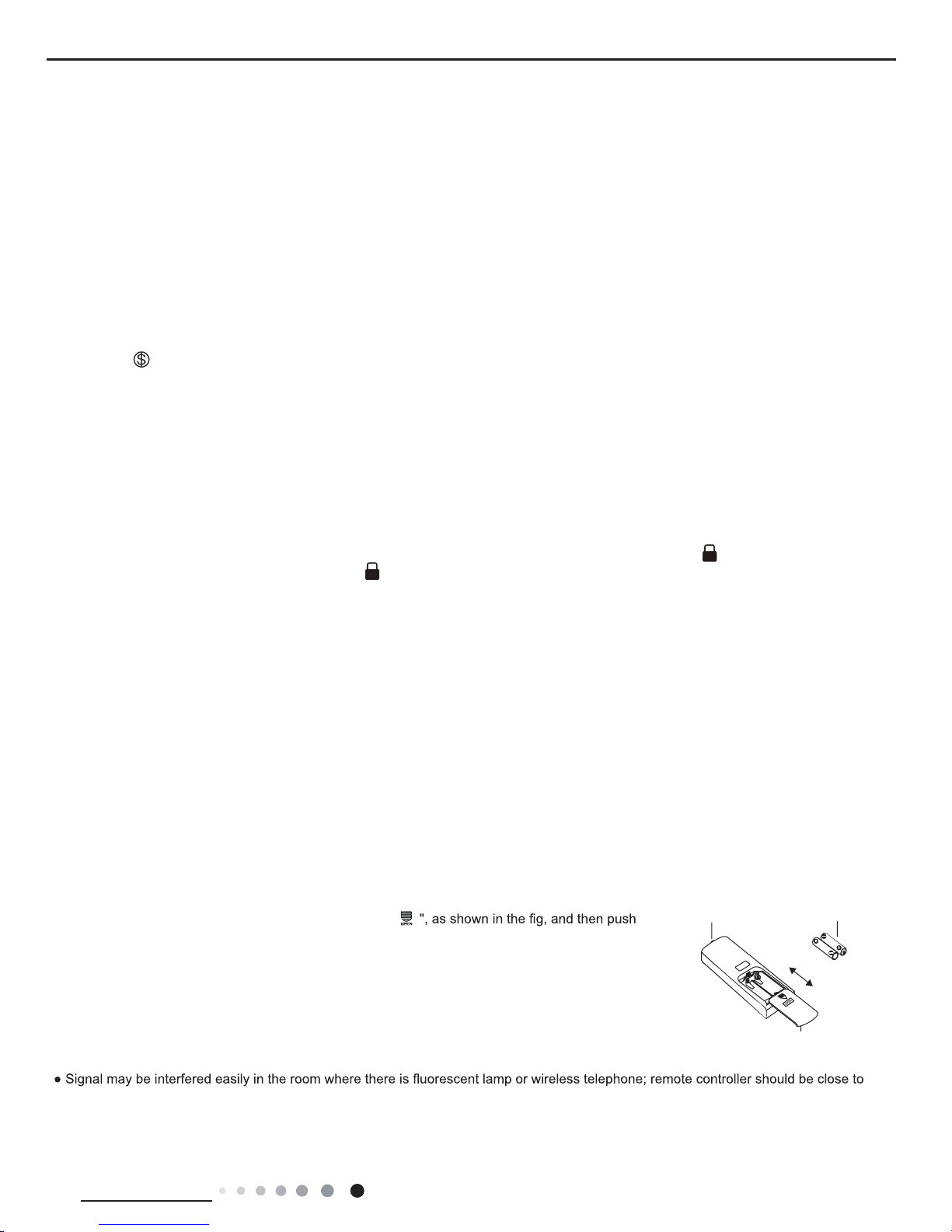
1. Press the back side of remote controller marked with "
out
the cover of battery box along the arrow direction.
2. Replace two 7# (AAA 1.5V) dry batteries, and make sure the position of "+" polar and "-" polar
are correct.
3. Reinstall the cover of battery box.
Note:
signal sender battery
Cover of battery box
remove
reinstall

20
Technical Information
Service Manual
6.2 Brief Description of Modes and Functions
1.Basic function of system
(1)Cooling mode
(1) Under this mode, fan and swing operates at setting status. Temperature setting range is 60.8~86.0OF.
(2) During malfunction of outdoor unit or the unit is stopped because of protection, indoor unit keeps original operation status.
(2)Drying mode
(1) Under this mode, fan operates at low speed and swing operates at setting status. Temperature setting range is 60.8~86.0OF.
(2) During malfunction of outdoor unit or the unit is stopped because of protection, indoor unit keeps original operation status.
(3) Protection status is same as that under cooling mode.
(4) Sleep function is not available for drying mode.
(3)Heating mode
(1) Under this mode, Temperature setting range is 60.8~86.0OF.
(2) Working condition and process for heating mode:
When turn on the unit under heating mode, indoor unit enters into cold air prevention status. When the unit is stopped or at OFF status,
and indoor unit has been started up just now, the unit enters into residual heat-blowing status.
(4)Working method for AUTO mode:
1.Working condition and process for AUTO mode:
a.Under AUTO mode, standard heating Tpreset=68.0OF and standard cooling Tpreset=77.0OF. The unit will switch mode automatically
according to ambient temperature.
2.Protection function
a. During cooling operation, protection function is same as that under cooling mode.
b. During heating operation, protection function is same as that under heating mode.
3. Display: Set temperature is the set value under each condition. Ambient temperature is (Tamb.-Tcompensation) for heat pump unit
and Tamb. for cooling only unit.
4. If there’s I feel function, Tcompensation is 0. Others are same as above.
(5)Fan mode
Under this mode, indoor fan operates at set fan speed. Compressor, outdoor fan, 4-way valve and electric heating tube stop operation.
Indoor fan can select to operate at high, medium, low or auto fan speed. Temperature setting range is 60.8~86.0OF.
2. Other control
(1) Buzzer
Upon energization or availably operating the unit or remote controller, the buzzer will give out a beep.
(2) Auto button
If press this auto button when turning off the unit, the complete unit will operate at auto mode. Indoor fan operates at auto fan speed
and swing function is turned on. Press this auto button at ON status to turn off the unit.
(3) Auto fan
Heating mode: During auto heating mode or normal heating ode, auto fan speed will adjust the fan speed automatically according to
ambient temperature and set temperature.
(4) Sleep
After setting sleep function for a period of time, system will adjust set temperature automatically.
(5) Timer function:
General timer and clock timer functions are compatible by equipping remote controller with different functions.
(6) Memory function
memorize compensation temperature, off-peak energization value.
Memory content: mode, up&down swing, light, set temperature, set fan speed, general timer (clock timer can’t be memorized).
After power recovery, the unit will be turned on automatically according to memory content.
(7) Health function
During operation of indoor fan, set health function by remote controller. Turn off the unit will also turn off health function.
Turn on the unit by pressing auto button, and the health is defaulted ON.

21
Technical Information
Service Manual
(8)I feel control mode
After controller received I feel control signal and ambient temperature sent by remote controller, controller will work according to the ambient
temperature sent by remote controller.
(9)Compulsory defrosting function
(1) Start up compulsory defrosting function
Under ON status, set heating mode with remote controller and adjust the temperature to 60.8OF. Press “+, -, +, -, +,-” button successively
within 5s and the complete unit will enter into compulsory defrosting status. Meanwhile, heating indicator on indoor unit will ON 10s and OFF
0.5s successively. (Note: If complete unit has malfunction or stops operation due to protection, compulsory defrosting function can be started
up after malfunction or protection is resumed.
(2) Exit compulsory defrosting mode
After compulsory defrosting is started up, the complete unit will exit defrosting operation according to the actual defrosting result, and the
complete unit will resume normal heating operation.
(10)Refrigerant recovery function:
(1) Enter refrigerant recycling function
Within 5min after energizing (unit ON or OFF status is ok), continuously press LIGHT button for 3 times within 3s to enter refrigerant
recycling mode; Fo is displayed and refrigerant recycling function is started. At this moment, the maintenance people closes liquid valve.
After 5min, stick the thimble of maintenance valve with a tool. If there is no refrigerant spraying out, close the gas valve immediately and
then turn off the unit to remove the connection pipe.
(2) Exit refrigerant recycling function
After entering refrigerant recycling mode, when receive any remote control signal or enter refrigerant recycling mode for 25min, the unit will
exit refrigerant recycling mode automatically If the unit is in standby mode before refrigerant recycling, it will be still in standby mode after
nishing refrigerant recycling; if the unit is in ON status before refrigerant recycling, it will still run in original operation mode.
(11)Ambient temperature display control mode
1. When user set the remote controller to display set temperature (corresponding remote control code: 01), current set temperature will be
displayed.
2. Only when remote control signal is switched to indoor ambient temperature display status (corresponding remote control code: 10) from
other display status (corresponding remote control code: 00, 01,11),controller will display indoor ambient temperature for 3s and then turn
back to display set temperature.
Under this mode, indoor fan operates at set fan speed. Compressor, outdoor fan, 4-way valve and electric heating tube stop operation.
Indoor fan can select to operate at high, medium, low or auto fan speed. Temperature setting range is 60.8~86.0OF.
(12)Off-peak energization function:
Adjust compressor’s minimum stop time. The original minimum stop time is 180s and then we change to:
The time interval between two start-ups of compressor can’t be less than 180+T s(0≤T≤15). T is the variable of controller. That’s to say
the minimum stop time of compressor is 180s~195s. Read-in T into memory chip when refurbish the memory chip each time. After power
recovery, compressor can only be started up after 180+T s at least.
(13) SE control mode
The unit operates at SE status.
(14) X-fan mode
When X-fan function is turned on, after turn off the unit, indoor fan will still operate at low speed for 2min and then the complete unit will be
turned off. When x-fan function is turned off, after turn off the unit, the complete unit will be turned off directly.
(15) 8º heating function
Under heating mode, you can set 8º heating function by remote controller. The system will operate at 8ºset temperature.
(16) Turbo fan control function
Set turbo function under cooling or heating mode to enter into turbo fan speed. Press fan speed button to cancel turbo wind.
No turbo function under auto, dry or fan mode.

22
Technical Information
Service Manual
Outdoor Units
1. Input Parameter Compensation and Calibration
(1) Check the ambient temperature compensation function Indoor ambient temperature compensation function.
a. In cooling mode, the indoor ambient temperature participating in computing control = (T
indoor ambient temperature
–⊿T
cooling indoor ambient temperature
compensation
)
b. In heating mode, the indoor ambient temperature participating in computing control= (T
indoor ambient temperature
–⊿T
heating indoor ambient temperature
compensation
)
(2) Check effective judgment controls of parameters
Effective judgment function of the outdoor exhaust temperature thermo-bulb When conditions a and b are satised, the outdoor exhaust
temperature thermo-bulb is judged not to be connected into place, the mainboard of outer units will display failure of the outdoor exhaust
temperature thermo-bulb (not connected into place), stop the machine for repairing, and resume the machine by remote controls of ON/
OFF.
a. Judgment of exhaust detection temperature change:
After the compressor starts up and runs for 10 minutes, if the compressor frequency f ≥ 40Hz, and the rising value Texhaust (T
exhaust (after start-
up for 10 minutes)
- T
exhaust (before start-up)
) <35.6ºF , the outdoor exhaust temperature thermo-bulb can be judged not to be connected into place (judging
once when the power is on the rst time).
b. Comparative judgment of exhaust detection temperature and condenser detection temperature (T
pipe temperature
= T
outdoor pipe temperature in cooling
mode
, T
pipe temperature
= T
indoor pipe temperature in heating mode
): After the compressor starts up and runs for 10 minutes, if the compressor frequency f ≥
40Hz, and T
pipe temperature
≥(T
exhaust+37.4
), the outdoor exhaust temperature thermobulb can be judged not to be connected into place (judging
once when power is on the rst time).
2. Basic Functions
(1) Cooling Mode
1. Conditions and processes of cooling operation:
(1) If the compressor is shut down, and [Tsetup – (T
indoor ambient temperature
– ⊿T
cooling indoor ambient temperature compensation)
] ≤ 32.9ºF , start up the
machine for cooling, the cooling operation will start;
(2) During operations of cooling, if 32ºF ≤ [Tsetup – (T
indoor ambient temperature
– ⊿T
cooling indoor ambient temperature compensation)
] < 35.6ºF , the cooling
operation will be still running;
(3) During operations of cooling, if 35.6ºF ≤ [Tsetup – (T
indoor ambient temperature
– ⊿T
cooling indoor ambient temperature compensation)
], the cooling operation
will stop after reaching the temperature point.
2. Temperature setting range
(1) If T
outdoor ambient temperature
≥ [T
low-temperature cooling temperature
], the temperature can be set at: 60.8~86ºF (Cooling at room temperature);
(2) If T
outdoor ambient temperature
< [T
low-temperature cooling temperature
], the temperature can be set at: 77~86ºF (Cooling at low temperature), that is, the
minimum setting temperature for outer units judgment is 77ºF .
(2) Dehumidifying Mode
1. Conditions and processes of dehumidifying operations: Same as the cooling mode;
2. The temperature setting range is: 60.8~86ºF;
(3) Air-supplying Mode
1. The compressor, outdoor fans and four-way valves are switched off;
2. The temperature setting range is: 60.8~86ºF.
(4) Heating Mode
1. Conditions and processes of heating operations: (Tindoor ambient temperature is the actual detection temperature of indoor environment
thermo-bulb, Theating indoor ambient temperature compensation is the indoor ambient temperature compensation during heating
operations)
(1) If the compressor is shut down, and [(T
indoor ambient temperature
– ⊿T
heating indoor ambient temperature compensation
) –T
setup
] ≤ 32.9ºF , start the machine
to enter into heating operations for heating;
(2) During operations of heating, if 32ºF ≤ [(T
indoor ambient temperature
–⊿ T
heating indoor ambient temperature compensation
) –T
setup
] < 35.6ºF , the heating
operation will be still running;
(3) During operations of heating, if 35.6ºF ≤ [(T
indoor ambient temperature
– ⊿T
heating indoor ambient temperature compensation
) –T
setup
], the heating operation
will stop after reaching the temperature point.
2. The temperature setting range in this mode is: 60.8~86ºF .

23
Technical Information
Service Manual
3. Special Functions
Defrosting Control
①
Conditions for starting defrosting
After the time for defrosting is judged to be satised, if the temperature for defrosting is satised after detections for continuous 3minutes,
the defrosting operation will start.
②
Conditions of nishing defrosting
The defrosting operation can exit when any of the conditions below is satised:
③
T
outdoor pipe temperature
≥ (T
outdoor ambient temperature
– [T
temperature 1 of nishing defrosting
];
④
The continuous running time of defrosting reaches [tmax. defrosting time].
4. Control Logic
(1) Compressor Control
Start the compressor after starting cooling, heating, dehumidifying operations, and the outer fans start for 5s; When the machine is
shutdown, in safety stops and when switching to air-supplying mode, the compressor will stop immediately. In all modes: once the
compressor starts up, it will not be allowed to stop until having run for the [tmin. compressor running time] (Note: including cases of
shutdown when the temperature point is reached; except the cases requiring stopping the compressor such as fault protection, remote
shutdown, mode switching etc.); In all modes: once the compressor stops, it will be allowed be restart after 3-minute delay (Note: The
indoor units have a function of power memory, the machine can be restarted after remote shutdown and powering up again without
delay).
1. Cooling mode
Start the machine to enter into cooling operation for cooling, the compressor is switched on.
2. Dehumidifying mode
Same as the cooling mode.
3. Air-supplying mode
The compressor is switched off.
4. Heating mode
(1) Start the machine to enter into heating operation for heating, the compressor is switched on.
(2) Defrosting:
a. Defrosting starts: the compressor is shut down, and restarts it after 55-second delay.
b. Defrosting ends: the compressor stops, then starts it after 55-second delay.
(2) Outer Fans Control
Notes:
Only the outer fans run for at least 80s in each air ow speed can the air ow be switched;
After the outer fans run compulsively in high speed for 80s when the machine starts up, control the air ow according to the logic.
After remote shutdown, safety stops, and when the machine stops after reaching the temperature point, as well as after the compressor
stops, extend 1 minute, the outer fans will stop (During the period in the 1 minute, the air ow of outer fans can be changed according to
the outdoor ambient temperature changes); When running with force, the outdoor fans shall run in the highest air ow.
(3) 4-way valve control
1. The 4-way valve control under the modes of Cooling, dehumidication and supplying air: closing;
2. The status of 4-way valve control under the heating mode: getting power;
(1) 4-way valve power control under heating mode
a. Starts the machine under heating mode, the 4-way valve will get power immediately.
(2) 4-way valve power turn-off control under heating mode
a. When you should turn off the power or switch to other mode under heating mode, the power of 4-way valve will be cut after 2 minutes
of the compressor stopped.
b. When all kinds of protection stops, the power of 4-way valve will be cut after delaying 4 minutes.
(3) Defrosting control under heating mode:
a. Defrosting begins: The power of 4-way valve will be cut after 50s of entering into the defrosting
compressor.
b. Defrosting stops: The 4-way valve will get power after 50s of exiting the defrosting compressor.
(4) Evaporator frozen-preventing protection function
At the mode of Cooling, dehumidifying:
Evaporator frozen-preventing protection function is allowed to begin after 6 min of starting the compressor.

24
Technical Information
Service Manual
1. Starting estimation:
After the compressor stopped working for 180s, if T
inner pipe
> [T
frozen-preventing frequency-limited temperature
(the temperature of hysteresis is 35.6ºF )],
the machine is only allowed to start for operating, otherwise it should not be started, and should be stopped to treat according to the frozen-
preventing protection: Clear the trouble under the mode of power turn-off / heating, and the protection times are not counted.
2. Frequency limited
[T
frozen-preventing normal speed frequency-reducing temperature
] ≤[T
inner pipe T frozen-preventing frequency-limited temperature
] , you should limit the frequency raising of
compressor.
3. Reducing frequency at normal speed:
If [T
frozen-preventing high speed frequency-reducing temperature
] ≤[T
inner pipe T frozen-preventing normal speed frequency-reducing temperature
], you should adjust the compressor
frequency by reducing 8Hz/90s till the lower limit;
4. Reducing frequency at high speed:
If [T
frozen-preventing power turn-off temperature
] ≤T
inner pipe
[T
frozen-preventing high speed frequency-reducing temperature
] you should adjust the compressor frequency by
reducing 30Hz/90s till the lower limit;
5. Power turn-off:
If the T
inner pipe
<[T
frozen-preventing power turn-off temperature
], then frozen-preventing protect to stop the machine; If T[
frozen-preventing frequency-limited temperature
]
<T
inner pipe
, and the compressor has stopped working for 3 minutes, the whole machine should be allowed to operate.
6. If the frozen-preventing protection power turn-off continuously occurs for six times, it should not be resumed automatically, and you should
press the ON/OFF button to resume if the fault keeps on. During the process of running, if the running time of compressor exceeds the t
evaporator frozen-preventing protection times zero clearing time , the times of frozen-preventing power turn-off should be cleared to recount.
The mode of stopping the machine or transferring to supply air will clear the trouble times immediately (if the trouble can not be resumed,
mode transferring will not clear it).
(5) Overload protection function
Overload protection function at the mode of Cooling and dehumidifying
1. Starting estimation:
After the compressor stopped working for 180s, if T
outer pipe
<[T
Cooling overload frequency-limited temperature
] (the temperature of hysteresis is 35.6ºF ), the
machine is allowed to start, otherwise it should not be started, and should be stopped to treat according to the overload protection: Clear the
trouble at the mode of power turn-off / heating, and the protection times are not counted.
2. Frequency limited
If [T
Cooling overload frequency-limited temperature
] ≤[T
outer pipe T Cooling overload frequency reducing temperature at normal speed
], you should limit the frequency raising of
compressor.
3. Reducing frequency at normal speed and power turn-off:
If [T
Cooling overload frequency reducing temperature at high speed
] ≤T
outer pipe
< [T
Cooling overload power turn-off temperature
] , you should adjust the compressor frequency
by reducing 8Hz/90s till the lower limit; After it was running 90s at the lower limit, if [T
Cooling overload frequency reducing temperature at normal speed
]≤T
outer pipe
,
then Cooling overload protects machine stopping;
4. Reducing frequency at high speed and stop machine:
If [T
Cooling overload frequency reducing temperature at high speed
]≤T
outer pipe
[T
Cooling overload power turn-off temperature
], you should adjust the compressor frequency by
reducing 30Hz/90s till the lower limit; After it was running 90s at the lower limit, if [T
Cooling overload frequency reducing temperature at normal speed
] ≤[T
outer pipe]
,
then Cooling overload protects machine stopping;
5. Power turn-off:
If the [T
Cooling overload power turn-off temperature
] ≤T
outer pipe
, then Cooling overload protects machine stopping; If [T
outer pipe
]<[T
Cooling overload frequency-limited
temperature
]and the compressor has been stopped working for 3 minutes, the machine should be allowed to operate.
6. If the Cooling overload protection power turn-off continuously occurs for six times, it should not be resumed automatically, and you should
press the ON/OFF button to resume if the fault keeps on. During the process of running, if the running time of compressor exceeds the t
overload protection times zero clearing time , the times of overload protection power turn-off should be cleared to recount. The mode of
stopping the machine or transferring to supply air will clear the trouble times immediately (if the trouble can not be resumed, transferring
mode will not clear it).
Overload protection function at the mode of heating
Starting estimation :
After the compressor stopped working for 180s, if T inner pipe T heating overload frequency-limited temperature (the temperature of
hysteresis is 35.6ºF ), the machine is allowed to start, otherwise it should not be started, and should be stopped to treat according to the
overload protection:
Clear the trouble at the mode of power turn-off / heating, and the protection times are not counted.

25
Technical Information
Service Manual
1. Frequency limited
If [T
heating overload frequency-limited temperature
]≤T
inner pipe
<[T
heating overload frequency reducing temperature at normal speed
] , you should limit the frequency raising of
compressor.
2. Reducing frequency at normal speed and stopping machine:
If T[
heating overload frequency reducing temperature at normal speed
]≤T
inner pipe
<[T
heating overload frequency reducing temperature at high speed
], you should adjust the compressor
frequency by reducing 8Hz/90s till the lower limit; After it was running 90s at the lower limit, if T heating overload frequency reducing
temperature at normal speed ≤T inner pipe, then overload protects machine stopping;
3. Reducing frequency at high speed and power turn-off:
If [T
heating overload frequency reducing temperature at high speed
]≤T
inner pipe
<[T
heating overload power turn-off temperature
], you should adjust the compressor frequency by
reducing 30Hz/90s till the lower limit; After it was running 90s at the lower limit, if T heating overload frequency reducing temperature at normal
speed ≤T outer pipe, then Cooling overload protects machine stopping;
4. Power turn-off:
If the [T
heating overload power turn-off temperature
] ≤T
inner pipe
, then overload protects machine stopping; If T inner pipe T heating overload frequency-limited
temperature and the compressor has been stopped working for 3 minutes, the machine should be allowed to operate.
5. If the overload protection power turn-off continuously occurs for six times, it should not be resumed automatically, and you should press
the ON/OFF button to resume if the fault keeps on. During the process of running, if the running time of compressor exceeds the t overload
protection times zero clearing time , the times of overload protection power turn-off should be cleared to recount. The mode of stopping the
machine or transferring to supply air will clear the trouble times immediately (if the trouble can not be resumed, transferring mode will not clear
it). Protective function for discharge temperature of compressor
1. Starting estimation:
After the compressor stopped working for 180s, if T
Discharge
<T
Discharge limited temperature
(the temperature of hysteresis is 35.6ºF ), the machine is
allowed to start, otherwise it should not be started, and should be stopped to treat according to the discharge temperature:
The machine should be stopped or transferred to supply air, the trouble should be cleared immediately, and the protection times are not
counted.
2. Frequency limited
If [T
Limited frequency temperature during discharging
] ≤T
Discharge
<[T
frequency reducing temperature at normal speed during discharging
] , you should limit the frequency raising of
compressor.
3. Reducing frequency at normal speed and stopping machine:
If [T
frequency reducing temperature at normal speed during discharging
] ≤T
Discharge
<[T
frequency reducing temperature at high speed during discharging
], you should adjust the compressor
frequency by reducing 8Hz/90s till the lower limit; After it was running 90s at the lower limit, if [T
frequency reducing temperature at normal speed during discharging
]
≤T
Discharge
, you should discharge to protect machine stopping;
4. Reducing frequency at high speed and power turn-off:
If [T
frequency reducing temperature at high speed during discharging
] ≤T
Discharge
<[T
Stop temperature during discharging
], you should adjust
the compressor frequency by reducing 30Hz/90s till the lower limit; After it was running 90s at the lower limit, if [T
frequency reducing temperature at normal
speed during discharging
] ≤T
Discharge
, you should discharge to protect machine stopping;
5. Power turn-off:
If the [T
Power turn-off temperature during discharging
] ≤T
Discharge
, you should discharge to protect machine stopping; If [T
Discharge
]<[T
Limited frequency temperature during
discharging
] and the compressor has been stopped for 3 minutes, the machine should be allowed to operate.
6. If the discharging temperature protection of compressor continuously occurs for six times, it should not be resumed automatically, and you
should press the ON/OFF button to resume. During the process of running, if the running time of compressor exceeds the t Protection times
clearing of discharge , the discharge protection is cleared to recount. Stopped or transferred to supply air mode will clear the trouble times
immediately (if the trouble can not be resumed, mode transferring also will not clear it).
7. Frequency limited
If [I
Limited frequency when overcurrent
] ≤I
AC Electric current
<[I
frequency reducing when overcurrent
], you should limit the frequency raising of compressor.
8. Reducing frequency:
If [I
Frequency reducing when overcurrent
] ≤[I
AC Electric current I Power turn-off when overcurrent
] , you should reduce the compressor frequency till the lower limit or exit
the frequency reducing condition;
9. Power turn-off:
If [I
Power turn-off machine when overcurrent
] ≤[I
AC Electric current
] , you should carry out the overcurrent stopping protection; If I
AC Electric current
<[T
Limited frequency when
overcurrent
] and the compressor has been stopped for 3 minutes, the machine should be allowed to operate.
10. If the overcurrent protection continuously occurs for six times, it should not be resumed automatically, and you should press the ON/OFF
button to resume. During the process of running, if the running time of compressor exceeds the [t
Protection times clearing of over current
] , the discharge
protection is cleared to recount.

26
Technical Information
Service Manual
(6)Voltage sag protection
After start the compressor, if the time of DC link Voltage sag [U
Sagging protection voltage
] is measured to be less than t Voltage sag protection time ,
the machine should be stop at once, hand on the voltage sag trouble, reboot automatically after 30 minutes.
(7)Communication fault
When you have not received any correct signal from the inner machine in three minutes, the machine will stop for communication fault. When
you have not received any correct signal from driver IC (aim to the controller for the separating of main control IC and driver IC), and the
machine will stop for communication fault. If the communication is resumed, the machine will be allowed to operate.
(8)Module protection
Testing the module protective signal immediately after started, once the module protective signal is measured, stop the machine with module
protection immediately. If the module protection is resumed, the machine will be allowed to operate. If the module protection continuously
occurs for three times, it should not be resumed automatically, and you should press the ON/OFF button to resume. If the running time of
compressor exceeds the [t
Protection times clearing of module
] , the module protection is cleared to recount.
(9)Module overheating protection
1. Starting estimation:
After the compressor stopped working for 180s, if T
Module
<[T
Module frequency limited temperature
](the temperature of hysteresis is 35.6ºF ), the machine
is allowed to start, otherwise it should not be started, and should be stopped to treat according to the module overheating protection: The
machine should be stopped or transferred to supply air, the trouble should be cleared immediately, and the protection times are not counted.
2. Frequency limited
If [T
Limited frequency temperature of module
] ≤T
Module
<[T
frequency reducing temperature at normal speed of module
] , you should limit the frequency raising of compressor.
3. Reducing frequency at normal speed and power turn-off:
If [T
frequency reducing temperature at normal speed of module
] ≤T
Module
<[T
frequency reducing temperature at high speed of module
], you should adjust the compressor frequency by
reducing 8Hz/90s till the lower limit; After it was running 90s at the lower limit, if [T
frequency reducing temperature at normal speed of module
] ≤T Module, you should
stop the machine for module overheating protection;
4. Reducing frequency at high speed and power turn-off:
If [T
frequency reducing temperature at high speed of module
]≤T
Module
<[T
Power turn-off temperature of module
] you should adjust the compressor frequency by reducing 30Hz/90s
till the lower limit; After it was running 90s at the lower limit, if [T
frequency reducing temperature at normal speed of module
] ≤T
Module
, you should stop the machine for
module overheating protection;
5. Power turn-off:
If the [T
Power turn-off temperature of module
] ≤T
Module
, you should stop the machine for module overheating protection; If T
Module
<[T
Limited frequency temperature of module
]
and the compressor has been stopped for 3 minutes, the machine should be allowed to operate.
6. If protection continuously occurs for six times, it should not be resumed automatically, and you should press the ON/OFF button to resume.
During the process of running, if the running time of compressor exceeds the [t
Protection times clearing of module
] , the discharge protection is cleared
to recount. Stopped or transferred to supply air mode will clear the trouble times immediately (if the trouble can not be resumed, mode
transferring also will not clear it).
(10)Compressor overloads protection
If you measure the compressor overload switch action in 3s, the compressor should be stopped for overloading. The machine should be
allowed to operate after overload protection was measured to resume. If the overloading protection continuously occurs for three times, it
should not be resumed automatically, and you should press the ON/OFF button to resume. The protection times of compressor is allowed to
clear after the compressor run [t
Protection times clearing of compressor overloading
] 30 minutes.
(11)Phase current overcurrent protection of compressor
During the running process of compressor, you could measure the phase current of the compressor, and control it according to the following
steps:
1. Frequency limited
If [I
Limited frequency phase current
] ≤[I
Phase current T frequency reducing phase current
] , you should limit the frequency raising of compressor.
2. Reducing Frequency
If [I
Frequency Reducing Phase Current
]≤I Phase Current<[I
Power Turn-Off Phase Current
], the compressor shall continue to reduce frequency till the lowest frequency
limit or out of the condition of reducing frequency;
3. Power turn-off
If [I
Phase Current
]≥[I
Power Turn-Off Phase Current
], the compressor phase current shall stop working for overcurrent protection; if [I
Phase Current
]≤[I
Frequency Reducing
Phase Current
], and the compressor have stopped working for 3 min, the machine shall be allowed to operate;
4. If the overcurrent protection of compressor phase current continuously occurs for six times, it should not be resumed automatically, and
you should press the ON/OFF button to resume. During the process of running, if the running time of compressor exceeds the [t
Clearing Time of
Compressor Phase Current Times
] , the overcurrent protection is cleared to recount.

27
Technical Information
Service Manual
(12) Starting-up Failure Protection for Compressor
Stop the compressor after its starting-up fails, restart it after 20s if the fault doesn’t shows, and if they are all failing for the successive start
3 times, it shall be reported as Starting-up Failure, and then restart up it after 3 min. When it still not be able to operate through carry out the
above process for 5 times, it is available if press ON/OFF. And the compressor should be cleared the times after it run 2 min.
(13) Out-of-Step Protection for Compressor
The out-of-step protection signal should be detected immediately after starting-up compressor, and once nd the out-of-step protection signal,
the out-of-step protection shall be stopped; if it can run for lasting power turn-off 3 min, the machine shall be allowed to operate. If it still can’t
run automatically when the out-of-step protection for compressor happens to stop working for 6 times in succession, it needs to press ON/OFF
to operate. And if the running time is more than 10 min, the power turn-off times for out-of-step protection shall be cleared and recounted.
(14) Voltage Abnormity Protection for DC Bus
To detect voltage abnormity protection for dc bus after completing the pre-charge:
1.Over-High Voltage Protection for DC Bus:
If it found the DCbus voltage UDC >[UDC
Jiekuangchun Protection
], turn off PFC and stop the compressor at once, and it shall show the DC over-high
voltage failure; it should clear out the failure when the voltage dropped to UDC <[UDC
Jiekuangchun Recovery
] and the compressor stopped for 3 min.
2.Over-Low Voltage Protection for DC Bus:
If it found the DC bus voltage UDC <[U
DC Wantuochun Protection
], turn off PFC and stop the compressor at once, and it shall show the DC over-low
voltage; and it should clear out the failure when the voltage raised to UDC >[U
DC Wantuochun Recovery
] and the compressor stopped for 3 min.
3.To detect voltage abnormity protect for DC bus when getting electricity:
If it found the DC bus voltage UDC >[U
DC——Over-High Voltage
], turn off the relay at once, and shows voltage abnormity failure for DC Bus. And the
failure can’t recover except to break off and get the electricity.
(15)Abnormity Protection for Four-way Valve
Under the model of heating operation in good condition: the compressor is detected [T
Inner Tube
<(T
Inner Ring-T Abnormity Temperature Difference For Four-Way Valve
Reversion
)], during the running, it should be regarded as four-way valve reversion abnormity. And then it can run if stop the reversion abnormity
protection for four-way valve 3 min; and if it still can’t run when the reversion abnormity protection for four-way valve happens to stop working
for 3 times in succession, it is available if presses ON/OFF.
Attention: the protection shall be shielded during the testing mode and defrosting process, and it shall be cleared out the failure and its times
immediately when turning off or delivering wind / cooling / dehumidifying mode conversed (the inverted mode don’t clear out the failure when it
can’t recover to operate).
(16) PFC Protection
1. After start up the PFC, it should detect the protection signal of PFC immediately; under the condition of PFC protection, it should turn off the
PFC and compressor at one time;
2. It shows the failure is cleared out if PFC Protection stopped working 3 min and recovers to run automatically;
3. If it still can’t run when it occurs PFC protection for 3 times in succession, it is available if presses ON/OFF; and clear the PFC Protection
times when start up PFC for 10min.
(17) Failure Detection for Sensor
1. Outdoor Ambient Sensor: detect the failure of sensor at all times.
2. Outdoor Tube Sensor: You should not detect the failure of outdoor tube sensor within 10 minutes heating
operation compressor except the defrosting, and you could detect it at other time.
3. Outdoor Exhaust Sensor:
(a) The compressor only detect the sensor failure after it start up 3 min in normal mode;
(b) It should detect the exhaust sensor failure immediately in the testing mode.
4. Module Temperature Sensor:
(a) Short-Circuit Detection: the compressor should be detected immediately when the module temperature
sensor occurs short-circuits;
(b) Open-Circuit Detection: the compressor should be detected on open-circuit when it runs 3min (it needn’t 30s
avoiding the module over-heated).
(c) Detect the sensor failure at all times in the testing mode.
5. Disposal for Sensor Protection
(1) When the short-circuit of sensor is detected within 30s, It is regarded as the temperature of sensor over-high (or innitely high), and now
according to the over-high sensor, the machine should carry out the corresponding protection to stop working, and show the corresponding
temperature shutdown protection and sensor failure at the same time (for example: the compressor stops immediately when the outdoor tube
sensor short-circuit, and the machine shall show the overload protection and outdoor tube sensor failure).
(2) When the open-circuit of sensor is detected within 30s, The protection shall be stopped and it shall show the corresponding sensor failure.
 Loading...