

Gree GWH18PD-K3NNA1A, GWH24PD-K3NNA1A Service Manual

GREE ELECTRIC APPLIANCES,INC.OF ZHUHAI
Service Manual
Change for Life
Models:GWH18PD-K3NNA1A(CA414000100)
GWH18PD-K3NNA1A(CA414000101)
GWH18PD-K3NNA1A(CA414000102)
GWH24PD-K3NNA1A(CA414000201)
GWH24PD-K3NNA1A(CA414000202)
(Refrigerant R410A)

Table of Contents
Table of Contents
Summary and Features
.........................................................................................1
1. Safety Precautions
..............................................................................................2
2. Specications
..........................................................................................................3
2.1 Unit Specications ............................................................................................................3
2.2 Capacity Variation Ratio According to Temperature .........................................................7
2.3 Operation Data .................................................................................................................7
3. Construction Views
............................................................................................8
3.1 Indoor Unit ........................................................................................................................8
3.2 Outdoor Unit .....................................................................................................................8
4. Refrigerant System Diagram
....................................................................10
5. Schematic Diagram
..........................................................................................11
5.1 Electrical Data ................................................................................................................11
5.2 Electrical Wiring ..............................................................................................................11
5.3 Printed Circuit Board ......................................................................................................15
6. Function and Control
......................................................................................16
6.1 Remote Controller Description ......................................................................................16
6.3 Description of Each Control Operation ...........................................................................20
7. Installation Manual
............................................................................................24
7.1 Notices for Installation ....................................................................................................24
7.2 Installation Drawing ........................................................................................................26
7.3 Install Indoor Unit ...........................................................................................................27
7.4 Installation of Outdoor Unit .............................................................................................28
7.5 Check after Installation and Test Operation ...................................................................29
7.6 Installation and Maintenance of Healthy Filter ...............................................................30

Table of Contents
8. Exploded Views and Parts List
..............................................................31
8.1 Indoor Unit ......................................................................................................................31
8.2 Outdoor Unit ...................................................................................................................34
9. Troubleshooting
..................................................................................................38
9.1 Precautions before Performing Inspection or Repair .....................................................38
9.2 Conrmation ...................................................................................................................38
9.3 Judgement by Flashing LED of Indoor/Outdoor Unit ......................................................38
9.4 How to Check Simply the Main Part ...............................................................................40
10. Removal Procedure
.......................................................................................47
10.1 Removal Procedure of Indoor Unit ...............................................................................47
10.2 Removal Procedure of Outdoor Unit ..........................................................................55
Summary and Features
1
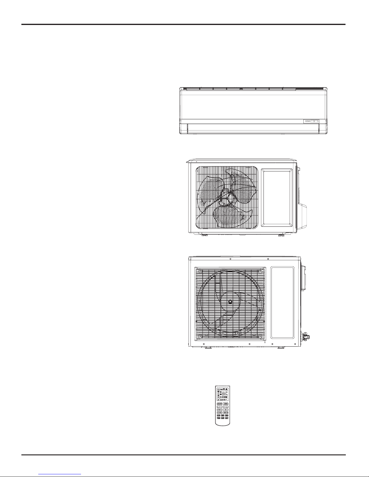
Summary and Features
Indoor Unit
Outdoor Unit
Remote Controller
YAM1F
GWH18PD-K3NNA1A/I(CA414N00100)
GWH18PD-K3NNA1A/I(CA414N00101)
GWH24PD-K3NNA1A/I(CA414N00201)
GWH24PD-K3NNA1A/I(CA414N00200)
GWH18PD-K3NNA1A/O
GWH24ND-K3NNB1A/O
2
Safety Precautions
1. Safety Precautions
Installing, starting up, and servicing air conditioner can be
hazardous due to system pressure, electrical components,
and equipment location, etc.
Only trained, qualified installers and service personnel are
allowed to install, start-up, and service this equipment.
Untrained personnel can perform basic maintenance functions such as cleaning coils. All other operations should
be performed by trained service personnel.
When handling the equipment, observe precautions in the
manual and on tags, stickers, and labels attached to the
equipment. Follow all safety codes. Wear safety glasses
andwork gloves. Keep quenching cloth and fire extinguisher
nearby when brazing.
Read the instructions thoroughly and follow all warnings or
cautions in literature and attached to the unit. Consult local
building codes and current editions of national as well as
local electrical codes.
Recognize the following safety information:
Incorrect handling could result in
personal injury or death.
Incorrect handling may result in
minor injury,or damage to product
or property.
Warning
Caution
Caution
Warning
All electric work must be performed by a licensed technician
according to local regulations and the instructions given in
this manual.
Before installing, modifying, or servicing system, main
electrical disconnect switch must be in the OFF position.
There may be more than 1 disconnect switch. Lock out
and tag switch with a suitable warning label.
Never supply power to the unit unless all wiring and tubing are completed, reconnected and checked.
This system adopts highly dangerous electrical voltage.
Incorrect connection or inadequate grounding can cause
personal injury or death. Stick to the wiring diagram and
all the instructions when wiring.
Have the unit adequately grounded in accordance with
local electrical codes.
All installation or repair work shall be performed by your dealer or a specialized subcontractor as there is the risk of fire,
electric shock, explosion or injury.
Have all wiring connected tightly. Loose connection may
lead to overheating and a possible fire hazard.
Make sure the outdoor unit is installed on a stable, level
surface with no accumulation of snow, leaves, or trash
beside.
Make sure the ceiling/wall is strong enough to bear the
weight of the unit.
Make sure the noise of the outdoor unit does not disturb
neighbors.
Follow all the installation instructions to minimize the risk
of damage from earthquakes, typhoons or strong winds.
Avoid contact between refrigerant and fire as it generates
poisonous gas.
Apply specified refrigerant only. Never have it mixed with
any other refrigerant. Never have air remain in the
refrigerant line as it may lead to rupture and other hazards.
Make sure no refrigerant gas is leaking out when installation is completed.
Should there be refrigerant leakage, the density of refrigerant in the air shall in no way exceed its limited value,
or it may lead to explosion.
Keep your fingers and clothing away from any moving
parts.
Clear the site after installation. Make sure no foreign objects are left in the unit.
Always ensure effective grounding for the unit.
Never install the unit in a place where a combustible gas
might leak, or it may lead to fire or explosion.
Properly insulate any tubing running inside the room to
prevent the water from damaging the wall.
Make a proper provision against noise when the unit is
installed at a telecommunication center or hospital.
Provide an electric leak breaker when it is installed in a
watery place.
Never wash the unit with water.
Should any emergency occur, stop the unit and disconnect the power immediately.
Handle unit transportation with care. The unit should not
be carried by only one person if it is more than 20kg.
Never touch the heat exchanger fins with bare hands.
Never touch the compressor or refrigerant piping without
wearing glove.
Do not have the unit operate without air filter.
3
Specications
2. Specications
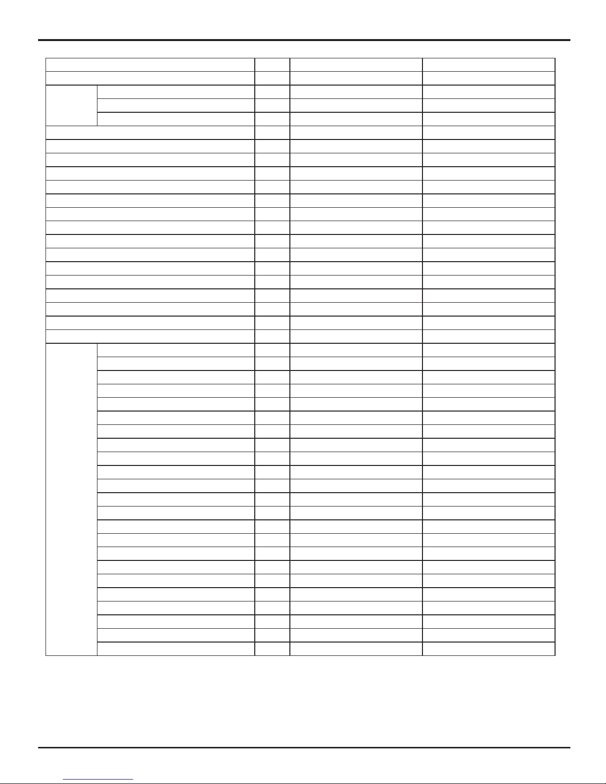
2.1 Unit Specications
Model GWH18PD-K3NNA1A GWH18PD-K3NNA1A
Product Code CA414000100 /CA414000101 CA414000102
Power
Supply
Rated Voltage V
~
220-240 220-240
Rated Frequency Hz 50 50
Phases 1 1
Power Supply Mode Indoor Indoor
Cooling Capacity W 4700 4700
Heating Capacity W 4900 4900
Cooling Power Input W 1460 1460
Heating Power Input W 1430 1430
Cooling Power Current A 6.50 6.50
Heating Power Current A 6.35 6.35
Rated Input W 1980 1980
Rated Current A 10 9.8
Air Flow Volume(SH/H/M/L/SL) m
3
/h 850/780/650/500/- 850/780/650/500/-
Dehumidifying Volume L/h 1.8 1.8
EER W/W 3.22 3.22
COP W/W 3.43 3.43
SEER W/W / /
HSPF W/W / /
Application Area m
2
23-34 23-34
Indoor Unit
Model of indoor unit GWH18PD-K3NNA1A/I GWH18PD-K3NNA1A/I
Fan Type Cross-ow Cross-ow
Diameter Length(DXL) mm Φ98X710 Φ98X710
Fan Motor Cooling Speed(SH/H/M/L/SL) r/min 1350/1200/1000/800/- 1350/1200/1000/800/-
Fan Motor Heating Speed(SH/H/M/L/SL) r/min 1420/1250/1100/950/- 1420/1250/1100/950/-
Output of Fan Motor W 20 20
Fan Motor RLA A 0.31 0.31
Fan Motor Capacitor μF 1.5 1.5
Input of Heater W / /
Evaporator Form Aluminum Fin-copper Tube Aluminum Fin-copper Tube
Pipe Diameter mm Φ7 Φ7
Row-n Gap mm 2-1.4 2-1.4
Coil Length (LXDXW) mm
715X25.4X304.8 715X25.4X304.8
Swing Motor Model MP28VB MP28VB
Output of Swing Motor W 2 2
Fuse A 3.15 3.15
Sound Pressure Level (SH/H/M/L/SL) dB (A) 45/42/37/33/- 45/42/38/34/-
Sound Power Level (SH/H/M/L/SL) dB (A) 55/52/47/43/- 55/52/48/44/-
Dimension (WXHXD) mm 945X298X200 945X298X200
Dimension of Carton Box (LXWXH) mm 1010X380X285 1010X380X285
Dimension of Package(LXWXH) mm 1013X383X300 1013X383X300
Net Weight kg 13 13
Gross Weight kg 17 17
4
Specications
The above data is subject to change without notice. Please refer to the nameplate of the unit.
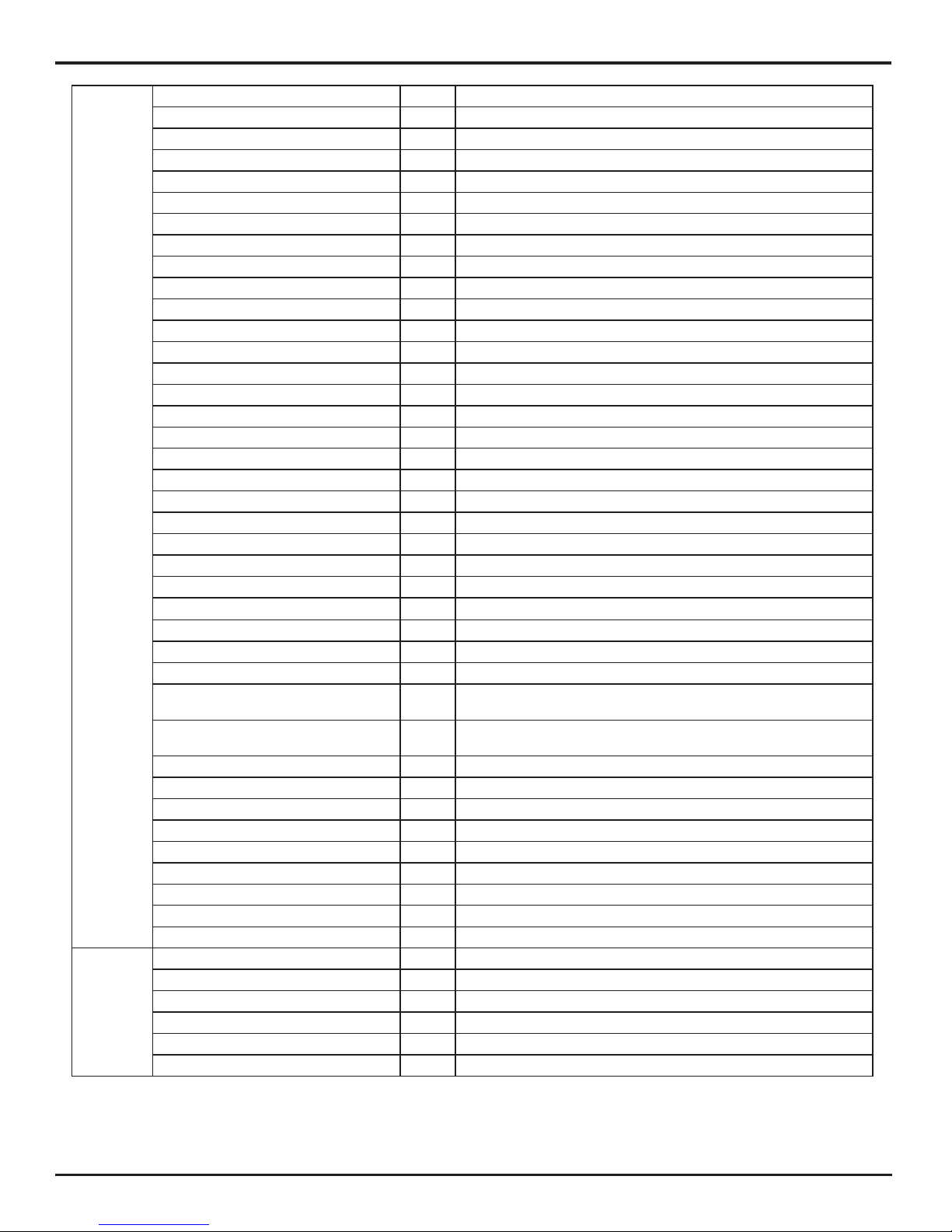
Outdoor
Unit
Model of Outdoor Unit GWH18PD-K3NNA1A/O GWH18PD-K3NNA1A/O
Compressor Manufacturer/Trademark
Shanghai Hitachi Electrical
Appliances Co.,Ltd
ZHUHAI LANDA
COMPRESSOR CO.,LTD.
Compressor Model ASL180SV-C7LU QXA-C18B030
Compressor Oil HAF68D1 RB68EP
Compressor Type Rotary Rotary
L.R.A. A 32 32
Compressor RLA A 6.8 7
Compressor Power Input W 1500 1520
Overload Protector UP3-83G Internal
Throttling Method Capillary Capillary
Operation Temp ºC 16~30 16~30
Ambient Temp (Cooling) ºC 18~43 18~43
Ambient Temp (Heating) ºC -7~24 -7~24
Condenser Form Aluminum Fin-copper Tube Aluminum Fin-copper Tube
Pipe Diameter mm Φ7 Φ7
Rows-n Gap mm 2-1.6 2-1.6
Coil Length (LXDXW) mm 735X25.4X495 735X25.4X495
Fan Motor Speed rpm 770 850
Output of Fan Motor W 35 35
Fan Motor RLA A 0.3 0.37
Fan Motor Capacitor μF 2.5 2.5
Air Flow Volume of Outdoor Unit m
3
/h 1800 1800
Fan Type Axial-ow Axial-ow
Fan Diameter mm Φ394.5 Φ394.5
Defrosting Method Automatic Defrosting Automatic Defrosting
Climate Type T1 T1
Isolation I I
Moisture Protection IP24 IP24
Permissible Excessive Operating
Pressure for the Discharge Side
MPa 4.3 4.3
Permissible Excessive Operating
Pressure for the Suction Side
MPa 2.5 2.5
Sound Pressure Level (H/M/L) dB (A) 55/-/- 55/-/-
Sound Power Level (H/M/L) dB (A) 65/-/- 65/-/-
Dimension (WXHXD) mm 848X540X320 848X540X320
Dimension of Carton Box (LXWXH) mm 878X360X580 878X360X580
Dimension of Package(LXWXH) mm
881X363X595 881X363X595
Net Weight kg 40 40
Gross Weight kg 44 44
Refrigerant R410A R410A
Refrigerant Charge kg 1.15 1.15
Connection
Pipe
Length m 4 5
Gas Additional Charge g/m 20 30
Outer Diameter Liquid Pipe mm Φ6 Φ6
Outer Diameter Gas Pipe mm Φ12 Φ12
Max Distance Height m 10 10
Max Distance Length m 25 25
5
Specications
Model GWH24PD-K3NNA1A GWH24PD-K3NNA1A
Product Code CA414000201 CA414000202
Power
Supply
Rated Voltage V
~
220-240 220-240
Rated Frequency Hz 50 50
Phases 1 1
Power Supply Mode Indoor Indoor
Cooling Capacity W 6155 6155
Heating Capacity W 6500 6500
Cooling Power Input W 1900 1900
Heating Power Input W 1900 1900
Cooling Power Current A 8.5 8.5
Heating Power Current A 8.8 8.8
Rated Input W 2700 2700
Rated Current A 15.7 15.7
Air Flow Volume(SH/H/M/L/SL) m
3
/h 850/780/650/500/- 850/780/650/500/-
Dehumidifying Volume L/h 1.8 1.8
EER W/W 3.24 3.24
COP W/W 3.42 3.42
SEER W/W / /
HSPF W/W / /
Application Area m
2
23-34 23-34
Indoor Unit
Model of indoor unit GWH24PD-K3NNA1A/I GWH24PD-K3NNA1A/I
Fan Type Cross-ow Cross-ow
Diameter Length(DXL) mm Φ98X710 Φ98X710
Fan Motor Cooling Speed(SH/H/M/L/SL) r/min 1350/1200/1000/800/- 1350/1200/1000/800/-
Fan Motor Heating Speed(SH/H/M/L/SL) r/min 1420/1250/1100/950/- 1420/1250/1100/950/-
Output of Fan Motor W 20 20
Fan Motor RLA A 0.31 0.31
Fan Motor Capacitor μF 1.5 1.5
Input of Heater W / /
Evaporator Form Aluminum Fin-copper Tube Aluminum Fin-copper Tube
Pipe Diameter mm Φ7 Φ7
Row-n Gap mm 2-1.4 2-1.4
Coil Length (LXDXW) mm
715X25.4X304.8 715X25.4X304.8
Swing Motor Model MP28VB MP28VB
Output of Swing Motor W 2 2
Fuse A 3.15 3.15
Sound Pressure Level (SH/H/M/L/SL) dB (A) 45/42/37/33/- 45/42/37/33/-
Sound Power Level (SH/H/M/L/SL) dB (A) 55/52/47/43/- 55/52/47/43/-
Dimension (WXHXD) mm 945X298X200 945X298X200
Dimension of Carton Box (LXWXH) mm 1010X380X285 1010X380X285
Dimension of Package(LXWXH) mm 1013X383X300 1013X383X300
Net Weight kg 13 13
Gross Weight kg 17 17
6
Specications
The above data is subject to change without notice. Please refer to the nameplate of the unit.
Outdoor
Unit
Model of Outdoor Unit GWH24ND-K3NNB1A/O
Compressor Manufacturer/Trademark Shanghai Hitachi Electrical Appliances Co.,Ltd/Highly
Compressor Model ASH232SV-C8LU
Compressor Oil HAF68D1 or equivalent
Compressor Type Rotary
L.R.A. A 40
Compressor RLA A 8.8
Compressor Power Input W 1900
Overload Protector Internal
Throttling Method Capillary
Operation Temp ºC 18~30
Ambient Temp (Cooling) ºC 18~43
Ambient Temp (Heating) ºC -7~24
Condenser Form Aluminum Fin-copper Tube
Pipe Diameter mm Φ7
Rows-n Gap mm 2-1.4
Coil Length (LXDXW) mm 865X38.1X660
Fan Motor Speed rpm 780
Output of Fan Motor W 68
Fan Motor RLA A 0.75
Fan Motor Capacitor μF 3
Air Flow Volume of Outdoor Unit m
3
/h 2800
Fan Type Axial-ow
Fan Diameter mm Φ460
Defrosting Method Automatic Defrosting
Climate Type T1
Isolation I
Moisture Protection IP24
Permissible Excessive Operating
Pressure for the Discharge Side
MPa 4.3
Permissible Excessive Operating
Pressure for the Suction Side
MPa 2.5
Sound Pressure Level (H/M/L) dB (A) 56/-/-
Sound Power Level (H/M/L) dB (A) 66/-/-
Dimension (WXHXD) mm 913X378X680
Dimension of Carton Box (LXWXH) mm 997X431X740
Dimension of Package(LXWXH) mm 1000X434X755
Net Weight kg 46
Gross Weight kg 50
Refrigerant R410A
Refrigerant Charge kg 1.45
Connection
Pipe
Length m 4
Gas Additional Charge g/m 20
Outer Diameter Liquid Pipe mm Φ6
Outer Diameter Gas Pipe mm Φ12
Max Distance Height m 10
Max Distance Length m 25
7
Specications
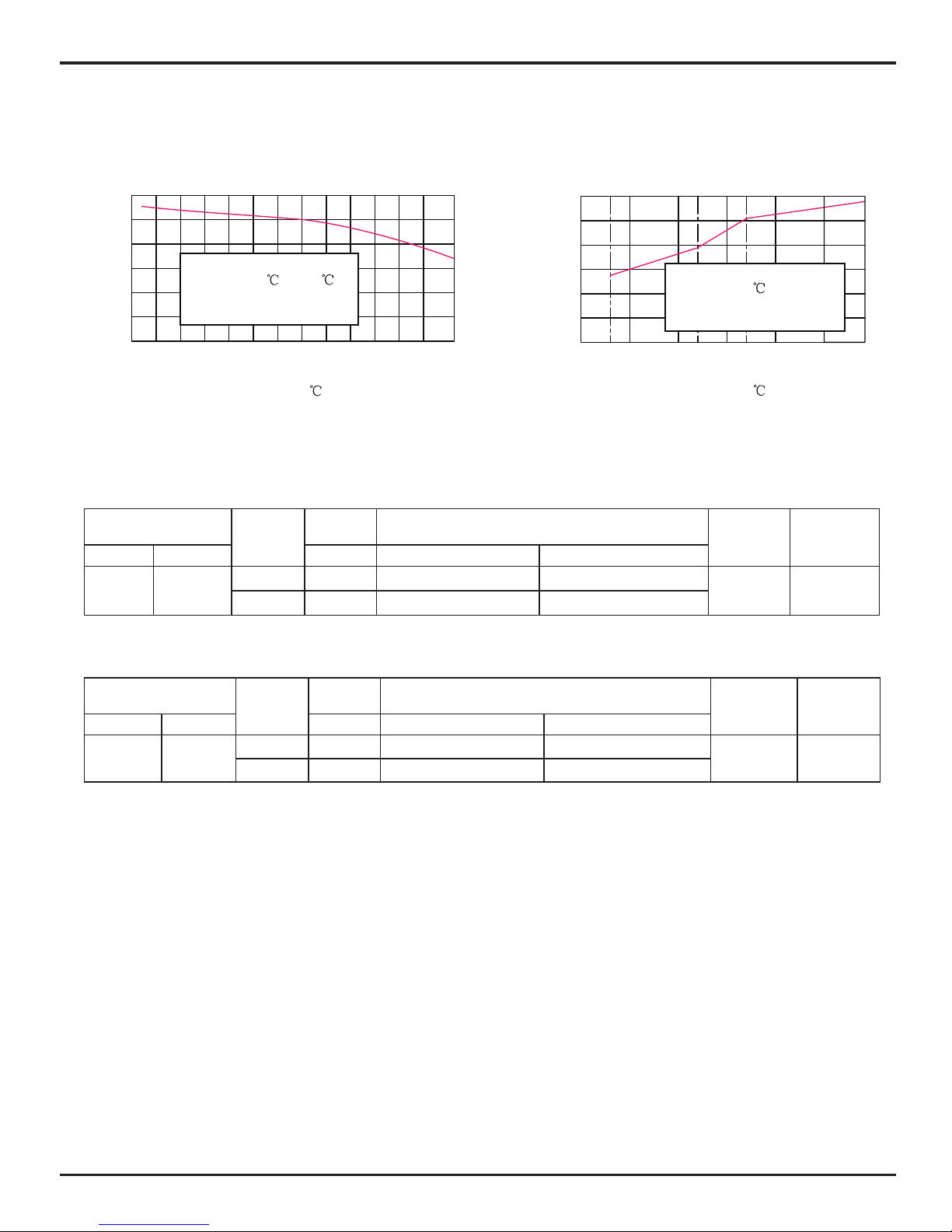
2.2 Capacity Variation Ratio According to Temperature
Cooling Heating
0
20
40
60
80
100
120
5 10
Outdoor t emp.( )
157-7-10 -5 0 2
Outdoor t emp.( )
4845434139373533312927252321
110
100
90
80
70
60
50
24
Condition Cooling
Indoor:DB27
WB19
Indoor air flow: Super High
Pipe length:4m or 5m
Condition Heating
Indoor:DB20
Indoor air flow: Super High
Pipe length:4m or 5m
Capacity ratio( )
%
Capacity ratio( )
%
2.3 Operation Data
Cooling
Temperature condition
(°C)
Model
name
Standard
pressure
Heat exchanger pipe temp.
Indoor fan
mode
Outdoor fan
mode
Indoor Outdoor P (MPa) T1 (°C) T2 (°C)
27/19 35/24
18K 0.8~0.9 in:8~11 out:11~12 in:75~85 out:37~43
Super High High
24K 0.8~1.0 in:8~11 out:11~14 in:75~85 out:36~43
NOTES :
(1) T1: Inlet and outlet pipe temperature of evaporator
T2: Inlet and outlet pipe temperature of condenser
P: Pressure of air pipe connecting indoor and outdoor units(on the side of gas pipe)
(2) Measure surface temperature of heat exchanger pipe around center of heat exchanger path U bent.(The rmistor the mometer)
(3) Connecting piping condition : 4m or 5m
Heating
Temperature condition
(°C)
Model
name
Standard
pressure
Heat exchanger pipe temp.
Indoor fan
mode
Outdoor fan
mode
Indoor Outdoor P (MPa) T1 (°C) T2 (°C)
20/- 7/6
18K 2.7~2.9 in:75~85 out:37~43 in:1~3 out:3~4
Super High High
24K 2.6~3.0 in:75~85 out:36~43 in:1~3 out:3~4
Construction Views
8
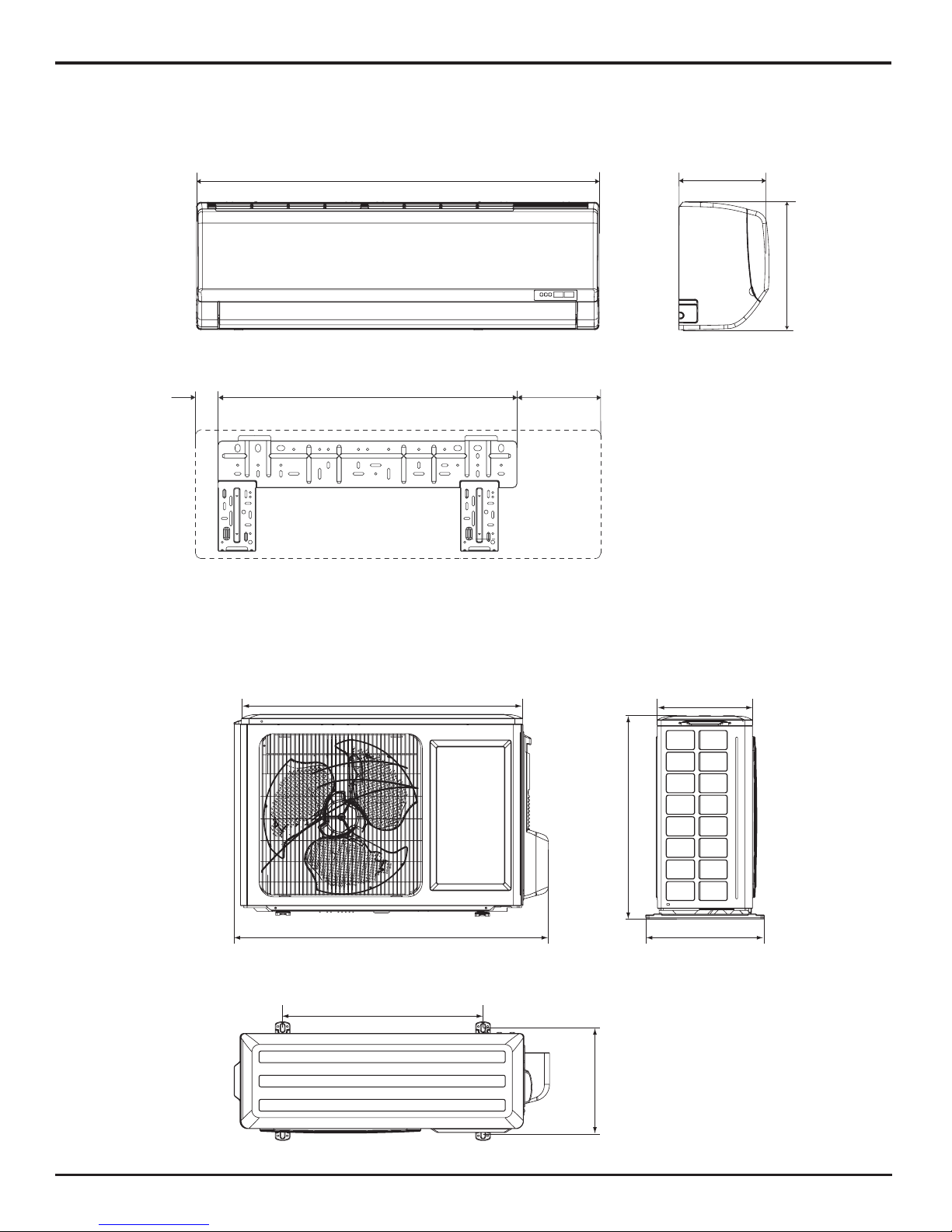
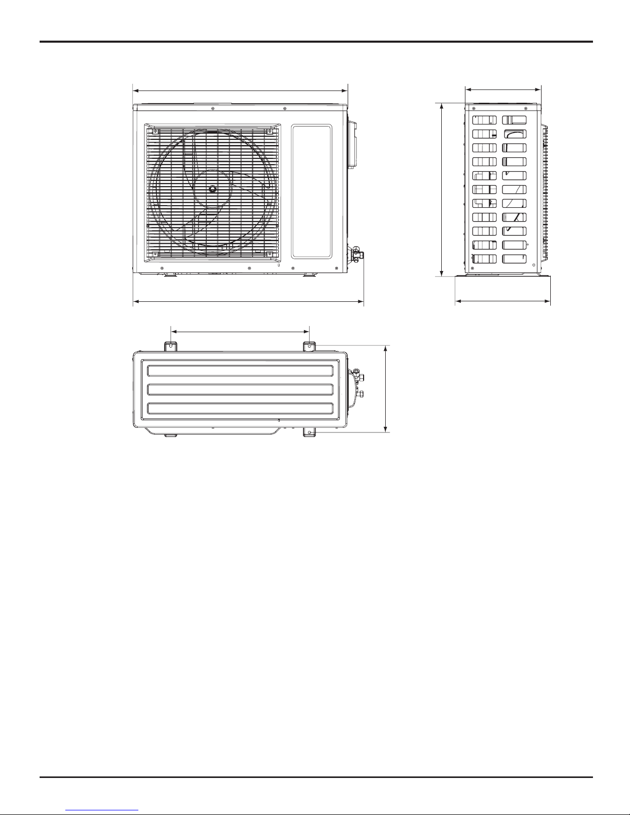
3. Construction Views
3.1 Indoor Unit
3.2 Outdoor Unit
848
257
540
286
320
762
540
694
945
200
298
194
57
Unit: mm
Unit: mm
18K
9
Construction Views
24K
847
300
913
680
378
549
348
Unit: mm
Refrigerant System Diagram
10
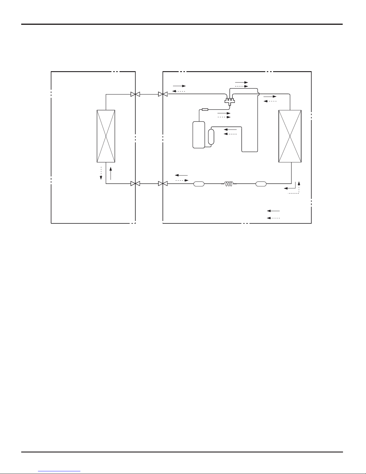
4. Refrigerant System Diagram
Refrigerant pipe diameter
Liquid : 1/4" (6 mm)
Gas : 1/2" (12mm)
TINU ROODTUOTINU ROODNI
HEAT
EXCHANGE
(EVAPORATOR)
HEAT
EXCHANGE
(CONDENSER)
COMPRESSOR
GAS SIDE
3-WAY VALVE
LIQUID SIDE
2-WAY VALVE
COOLING
HEATING
Accumlator
Discharge
Suction
Muffler
4-Way valve
Capillary reniartSreniartS
11
Schematic Diagram
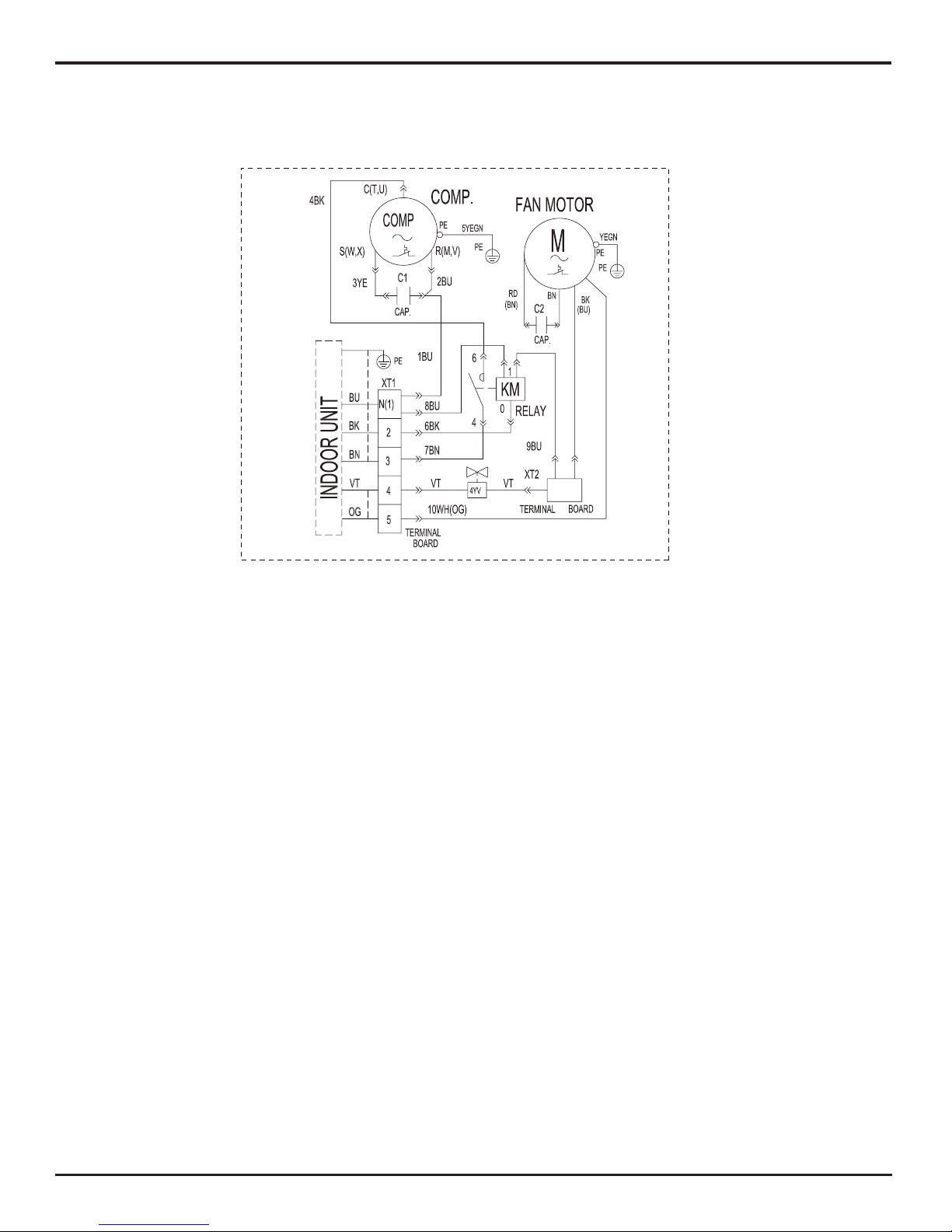
5. Schematic Diagram
5.1 Electrical Data
Meaning of marks
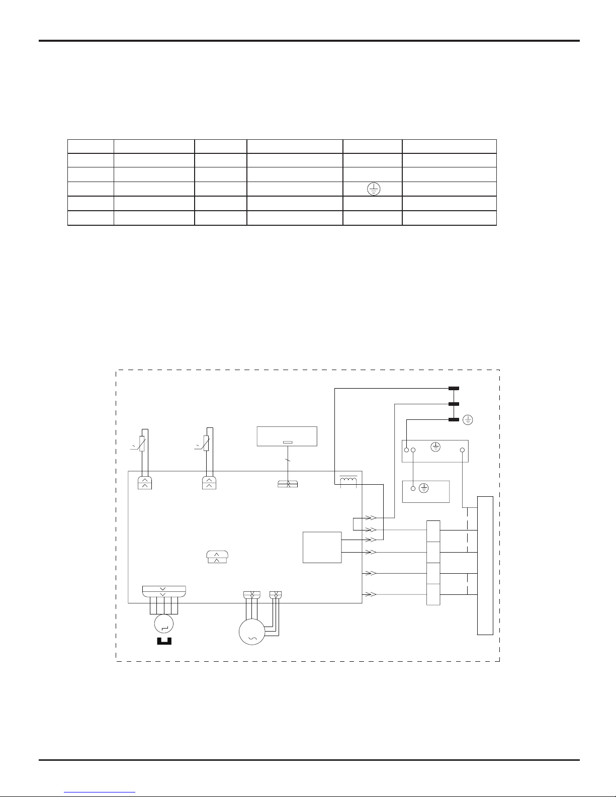
5.2 Electrical Wiring
Symbol Color symbol Symbol Color symbol Symbol Parts name
WH WHITE GN GREEN SAT OVERLOAD
YE
YELLOW
BN
BROWN COMP COMPRESSOR
RD
RED
BU
BLUE PROTECTIVE EARTH
YEGN
YELLOW GREEN
BK
BLACK
/ /
VT VIOLET
OG ORANGE
/ /
● Indoor Unit
GWH18PD-K3NNA1A/I(CA414N00100)
COMP
L(AC-L)
DISP1
AP1
DISPLAY BOARD
RECEIVER AND
AP1 PRINTED CIRCUIT BOARD
JUMP
CAP
M1
PG
PGF
FAN MOTOR
BU
BK
VT
OG
YEGN
YEGN
EVAPORATOR
PE
PE
EARTH-PLATE
N1
BU
BK
XT
4V
OFAN
VT
OG
K1
5
4
2
N(1)
M2
OUTDOOR UNIT
ROOM
RT2
RT1
TUBE
SENSOR
SENSOR
ROOM TEMP.
TUBE TEMP.
L101
BLOCK
TERMINAL
YEGN(GN)
BU(WH)
BN(BK)
POWER
STEPPING MOTOR
SWING-UD
(SWING)
0
0
L
N
12
Schematic Diagram
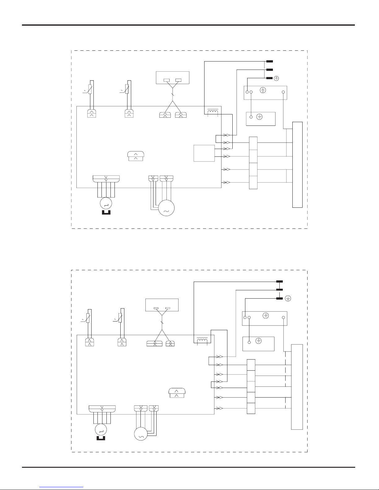
GWH18PD-K3NNA1A/I(CA414N00101)
GWH24PD-K3NNA1A/I(CA414N00201)
L(4)
COMP(3)
BU
BK
VT
OG
POWER
EVAPORATOR
PE
PE
EARTH-PLATE
BU
BK
XT
VT
OG
5
4
2
N(1)
OUTDOOR UNIT
CAP
JUMP
AP1 PRINTED CIRCUIT BOARD
RT2
RT1
AP2
BU(WH)
BN(BK)
YEGN(GN)
CABLE
CONNECTING
TEMP.ROOM
SENSOR
YEGNYEGN
BLOCK
TERMINAL
TEMP.TUBE
SENSOR
M1
PGF
PG
FAN MOTOR
DISPLAY BOARD
RECEIVER AND
DISP1
DISP2
TUBE
ROOM
L101
M2
(SWING)
SWING-UD
STEPPING MOTOR
N1
4V
OFAN
K1
DISPLAY
0
0
N
L
DISPLAY
VT
BN
COMP
OG
BN
BK
BU
3
OG
VT
YEGN
YEGN
EVAPORATOR
PE
PE
EARTH-PLATE
OFAN
4V
5
4
XT
2
N(1)
OUTDOOR UNIT
CAP
JUMP
AP1 PRINTED CIRCUIT BOARD
ROOM
RT2
RT1
TUBE
SENSOR
SENSOR
ROOM
TUBE
BN(BK)
BU(WH)
L
BK
BU
N
YEGN(GN)
N1
L101
RECEIVER AND
DISPLAY BOARD
DISP2
AP2
DISP1
CABLE
TERMINAL
BLOCK
CONNECTING
POWER
TEMP.
TEMP.
M2
SWING-UD
STEPPING MOTOR
(SWING)
M1
FAN MOTOR
PG
PGF
L(AC-L)
0
0

13
Schematic Diagram
● Outdoor Unit
GWH24PD-K3NNA1A/I(CA414N00200)
GWH18PD-K3NNA1A/O
0
0
DISP1
AP1
DISPLAY BOARD
L101
N1
YEGN(GN)
BU
BK
BU(WH)
BN(BK)
POWER
TUBE TEMP.
ROOM TEMP.
SENSOR
SENSOR
TUBE
RT1
RT2
ROOM
AP1 PRINTED CIRCUIT BOARD
JUMP
CAP
OUTDOOR UNIT
N(1)
2
XT
4
5
4V
OFAN
EARTH-PLATE
PE
PE
EVAPORATOR
YEGN
YEGN
VT
OG
3
BU
BK
BN
OG
COMP
BN
VT
L
PGF
PG
M1
STEPPING MOTOR
M2
FAN MOTOR
RECEIVER AND
BLOCK
TERMINAL
CONNECTING
CABLE
SWING-UD
(SWING)
N
L
14
Schematic Diagram
These circuit diagrams are subject to change without notice, please refer to the one supplied with the unit.
GWH24ND-K3NNB1A/O
YEGN
15
Schematic Diagram
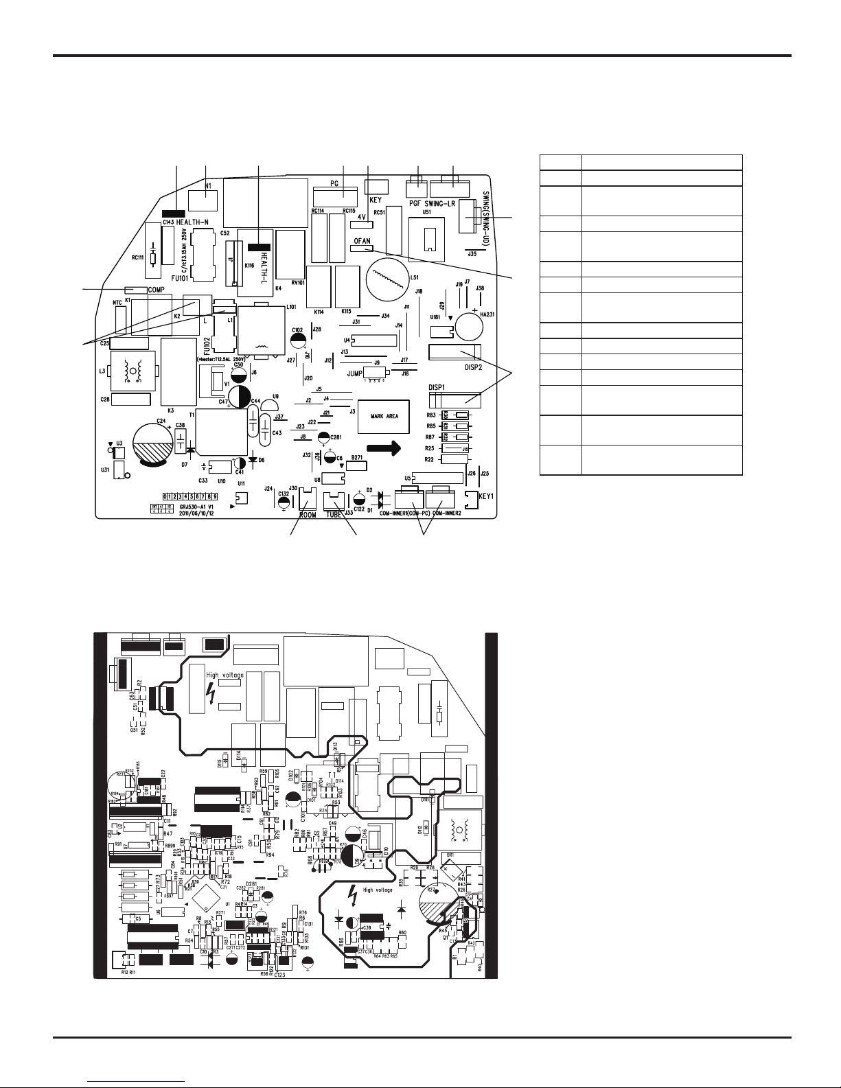
5.3 Printed Circuit Board
●TOP VIEW
●BOTTOM VIEW
1
2
3 4 5 6 7 8 9
10
11
12
131415
1 Interface of live wire
2 Interface of compressor
3
Interface of neutral wire for
health function
4 Interface of neutral wire
5
Interface of live wire for
health function
6 Control terminal of PG motor
7 Interface of 4-way valve
8
Feedback interface of PG
motor
9 Left&right swing
10 Up&down swing
11 Interface of outdoor fan
12 Display interface
13
Interface of remote control
motor
14
Interface of indoor tube
temperature sensor
15
Interface of indoor ambient
temperature sensor
Function and Control
16
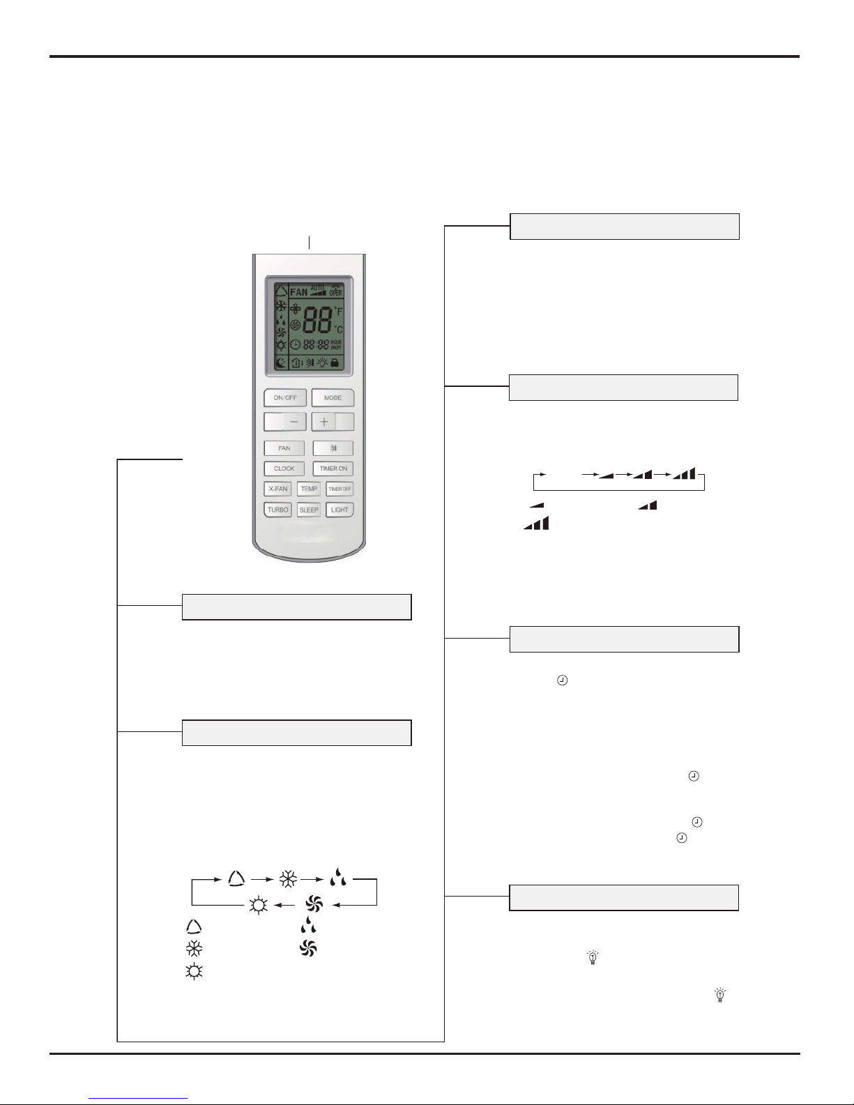
6. Function and Control
6.1 Remote Controller Description
●
Press thisbutton to select LIGHT on or off
in the displayer. When the LIGHT on is
LIGHT button
LIGHT
set,the icon will be displayed and the
indicator light in the displayer will be on.
When the LIGHT off is set, the icon will
be displayed and the indicator light in
the displayer will be off.
●
ON/OFF button
ON/OFF
Remote control
Signal transmitter
AUTO
COOL
DRY
FAN
HEAT
(Only for cooling and heating unit.
As for cooling only unit, it won’t
have any action when it receives
the signal of heating operation.)
Middle fan
●
Press this button, Auto, Cool, Dry, Fan,
Heat mode can be selected circularly.
MODE button
MODE
Auto mode is default while power on.
Under Auto mode, the temperature will not
eht ,edom taeH rednU ;deyalpsid eb
initial value is 28ć
;Under other
modes,
the initial value is 25ć .
●
Press this button, Sleep On and Sleep
Off can be selected. After powered on,Sleep
SLEEP button
SLEEP
Off is defaulted. After the unit is turned
off, the Sleep function is canceled. After
Sleep function set up, the signal of Sleep
will di splay. In this mode, the time of timer
can be adjusted. Under Fan and Auto
modes, this function is not available.
●
Press this button, Auto, Low, Middle, High
sp eed can be c i rc ul arl y se l ecte d. Aft er
FAN button
FAN
powered on,Auto fan speed is default.
Low fan
AUTO
High fan
●
Press this button, the clock can b e set up,
signal blink and display.Within 5
CLOCK button
CLOCK
seconds, the value can be adjusted by
pressing + or - button, if continuously
press this button for 2 seconds above,
in every 0.5 sec onds, the value on ten place
of Minute will be increase d 1. During blin king,
repress the Clock button, signal will be
constantly displayed and it denotes the
sett ing succeeded. After powered on, 12:0 0
is defaulted to display and signal will
be displayed. If there is signal be
value is Clock value, otherwise is Timer value.
displayed t hat denotes the current time
(
o
F)
82
(
o
F)
77
Press this button, the unit will be turned on,
press it once more, the unit will be turned
off. When turning on or turning off the unit,
the Timer, Sleep function will be canceled,
but the presetting time is still remained.
adjustable, low fan speed is imperative,
Note:Under the Dry mode, the fan speed isn't
adjustable, low fan speed is imperative,
but wh en op erating this bu tt on, the wireless
Names and Functions of Wireless Remote Control
Note: Be sure that there are no obstructions between receiver and remote controller ;Don't drop or throw the remote control; Don't let
any liquid in the remote control and put the remote control directly under the sunlight or any place where is very hot.
Function and Control
17
Remote control
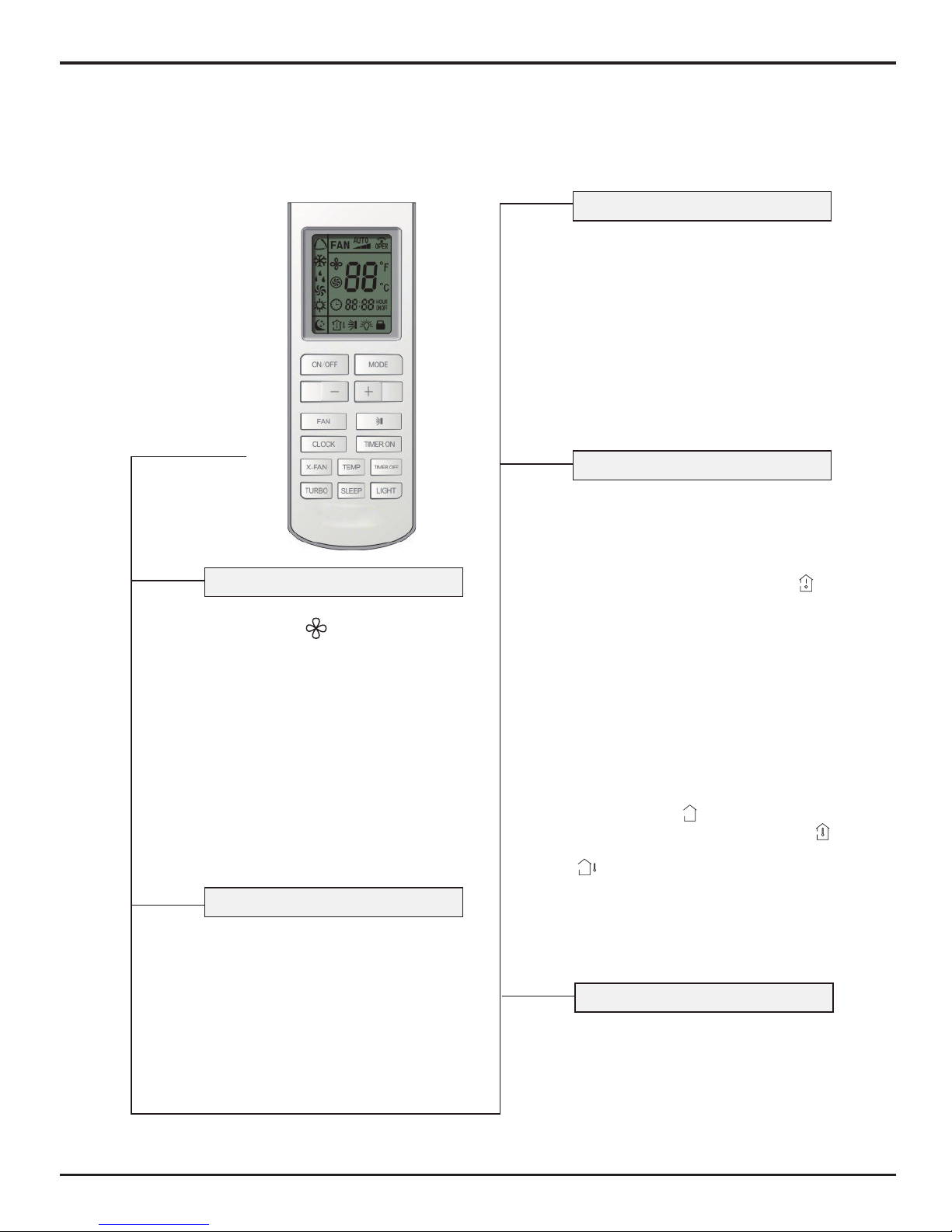
●
X-FAN button
X-FAN
●
TURBO button
TURBO
●
+ button
+
● Presetting temperature can be decreased.
Press this button, the temperature can be
- button
-
set up, continuously press this button
and hold for two seconds, the relative
contents can quickly change, until unhold
this button and send the order that theć
(
o
F) signal will be displayed all the time.
The temperature adjustment is unavailable under the Auto mode, but the order
can be sent by if pressing this button.
In Cool or Heat mode, press this button
can turn on or turn off the Turbo function.
After turned on the Turbo function, its
signal will be displayed. When switching
the mode or changing fan speed, this
function will be canceled automatically.
For presetting temperature increasing.
Press this button,can set up the temperature,
when unit is on. Continuously press and
hold this button for more than 2 seconds,
the corresponding contents will be
changed rapidly, until unpress the button
ć˄˅
llaying all along. In Auto mode, the temp-
erature can not be set up, but operate this
button can send the signal. Centigrade
setting range:16-30; Fahrenheit scale
setting range 61-86.
then send the information, is disp-
TEMP button
TEMP
●
Press this button, could select displaying
the indoor setting temperature or indoor
ambient temperature.When the indoor unit
firstly power on it will display the setting
temperature, if the temperature's displaying
," "ot sutats rehto morf degnahc si sutats
displays the ambient temperature, 5s later
or within 5s, it receives other remote control
signal that will return to display the setting
temperature. if the users haven't set up the
temperature displaying status,that will
display the setting temperature.
●
After powered on, the setting temperature
displaying is defaulted, (according to
customers requirements to display, if
there is no requirement that will default
to display the presetting temperature
and there is no icon displayed on wireless
remote control). Press this button,
(When displaying ), will display
presetting temperature; (when displaying )
will display indoor ambient temperature,
current displaying status will not be
changed. If current displays indoor
ambient temperature, if received the other
remote control signal, it will display
presetting temperature, 5s later, will back
to display the ambient temperature.
(This function is applicable to partial ofmodels)
(This function is applicable to partial of models)
PressingX-FAN button in COOL or DRY
mode,the icon
After energization, X-FAN OFF is defaulted.
X-FAN is not available in AUTO,FAN or
HEAT mode.
is displayed and the
indoor fan will continue operation for
10 minutes in order to dry the indoor unit
even though you have turned off the unit.
Notice: This is a general use remote controller, it could be used for the air conditioners with multifunction; For some function, which the
model dosen't have, if press the corresponding button on the remote controller that the unit will keep the original running status.
Function and Control
18
OFF
This is an universal use remote controller. If
remote controller sends the following three
kinds of status that the swing status of main
unit will be:
When the guide louver start to swing up and
down, if turn off the Swing, the air guide louver
will stop at current position.
which indicates the guide louver swings up
and down between that all five positions.
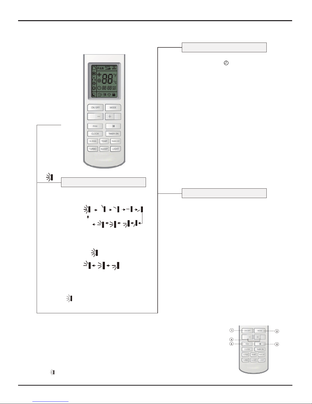
●
Press this button, to set up swing angle,
which circularly changes as below:
SWING UP AND DOWN BUTTON
TIMER ON
TIMER ON BUTTON
Timer On setting: Signal “ON” will blink
and display, signal will conceal, the
numerical section will become the timer
on setting status. During 5 seconds blink,
by pressing + or - button to adjust the
time value of numerical section, every
press of that button, the value will be
increased or decreased 1 minute. Hold
pressing + or -button, 2 seconds later,
it quickly change, the way of change is:
During the initial 2.5 seconds, ten numbers
change in the one place of minute, then
the one place is constant, ten numbers
change in the tens place of minute at 2.5
seconds speed and carry. During 5s blink,
press the Timer button, the timer setting
succeeds. The Timer On has been set up,
repress the timer On button, the Timer
On will be canceled. Before setting the
Timer, please adjust the Clock to the
current actual time.
TIMER OFF BUTTON
Once press this key to enter into
TIMER OFF setup, in which case
the TIMER OFF icon will blink.
The method of setting is the same
as for TIMER ON.
TIMER OFF
●
Remote control
●
Notice: This is a general use remote controller, it could be used for the air conditioners with multifunction; For some function, which the
model dosen't have, if press the corresponding button on the remote controller that the unit will keep the original running status.
Guide for Operation - General Operation
1. After powered on, press ON/OFF button, the unit will start to run. (Note: When it is powered
on, the guide louver of main unit will close automatically.)
2. Press MODE button, select desired running mode.
3. Pressing + or - button, to set the desired temperature. (It is unnecessary to set the temp. at
AUTO mode.)
4. Pressing FAN button, set fan speed, can select AUTO FAN, LOW, MID and HIGH.
5. Pressing button, to select the swing.
 Loading...