

Gree GWH18MC-D3DNA5F/I, GWC24MD-D3DNA3F/I, GWH24MD-D3DNA8F/I, GWC18MC-D3DNA5F/I, GWH18MC-D3DNA3F/I Service Manual
...
GREE ELECTRIC APPLIANCES,INC.OF ZHUHAI
Change for Life
Service Manual
Model:GWC18MC-D3DNA3F
GWC18MC-D3DNA5F
GWH18MC-D3DNA3F
GWH18MC-D3DNA5F
GWH18MC-D3DNA8F
GWC24MD-D3DNA3F
GWC24MD-D3DNA5F
GWH24MD-D3DNA3F
GWH24MD-D3DNA5F
GWH24MD-D3DNA8F
(Refrigerant R410A)

Service Manual
Table of Contents
Table of Contents
Part
Ⅰ
: Technical Information
......................................................................... 1
1. Summary
........................................................................................................................ 1
2. Specications
............................................................................................................ 2
2.1 Specication Sheet ............................................................................................................. 2
2.2 Operation Characteristic Curve ........................................................................................ 10
2.3 Capacity Variation Ratio According to Temperature ......................................................... 10
2.4 Cooling and Heating Data Sheet in Rated Frequency ......................................................11
2.5 Noise Curve .......................................................................................................................11
3. Outline Dimension Diagram
........................................................................ 12
3.1 Indoor Unit ........................................................................................................................ 12
3.2 Outdoor Unit ..................................................................................................................... 13
4. Refrigerant System Diagram
...................................................................... 14
5. Electrical Part
........................................................................................................... 15
5.1 Wiring Diagram ................................................................................................................. 15
5.2 PCB Printed Diagram ....................................................................................................... 20
6. Function and Control
........................................................................................ 24
6.1 Remote Controller Introduction ........................................................................................ 24
6.2 Brief Description of Modes and Functions ........................................................................ 28
Part
Ⅱ
: Installation and Maintenance
................................................... 35
7. Notes for Installation and Maintenance
............................................ 35
8. Installation
.................................................................................................................. 37
8.1 Installation Dimension Diagram ........................................................................................ 37
8.2 Installation Parts-checking .............................................................................................. 39
8.3 Selection of Installation Location ...................................................................................... 39
8.4 Electric Connection Requirement .................................................................................... 39
8.5 Installation of Indoor Unit .................................................................................................. 39
8.6 Installation of Outdoor Unit ............................................................................................... 42
8.7 Vacuum Pumping and Leak Detection ............................................................................. 43
8.8 Check after Installation and Test Operation ..................................................................... 43

Service Manual
9. Maintenance
.................................................................................................................44
9.1 Precautions before Maintenance ......................................................................................... 44
9.2 Error Code List .................................................................................................................... 45
9.3 Troubleshooting for Main Malfunction ................................................................................. 56
9.4 Troubleshooting for Normal Malfunction ..............................................................................70
10. Exploded View and Parts List
................................................................... 72
10.1 Indoor Unit .........................................................................................................................72
10.2 Outdoor Unit ......................................................................................................................82
11. Removal Procedure
............................................................................................ 92
11.1 Removal Procedure of Indoor Unit .................................................................................... 92
11.2 Removal Procedure of Outdoor Unit ...............................................................................102
Appendix:
........................................................................................................................... 112
Appendix 1: Reference Sheet of Celsius and Fahrenheit ....................................................... 112
Appendix 2: Conguration of Connection Pipe ........................................................................ 112
Appendix 3: Pipe Expanding Method ...................................................................................... 113
Appendix 4: List of Resistance for Temperature Sensor ......................................................... 114
1
Technical Information
Service Manual
1. Summary
Part
Ⅰ
: Technical Information
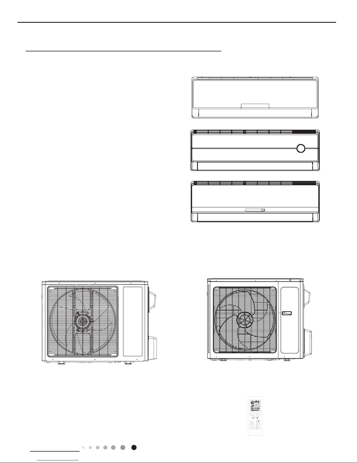
Indoor Unit:
GWC18MC-D3DNA3F/I
GWH18MC-D3DNA3F/I
GWC24MD-D3DNA3F/I
GWH24MD-D3DNA3F/I
GWH18MC-D3DNA8F/I
GWH24MD-D3DNA8F/I
GWC18MC-D3DNA5F/I
GWH18MC-D3DNA5F/I
GWC24MD-D3DNA5F/I
GWH24MD-D3DNA5F/I
Outdoor Unit:
GWC18MC-D3DNA3D/O
GWH18MC-D3DNA3D/O
GWH18MC-D3DNA3D/O(electric heating band)
GWC24MD-D3DNA3D/O
GWH24MD-D3DNA3D/O
GWH24MD-D3DNA3D/O(electric heating band)
Remote Controller:
YB1FAF(XFAN)
ON/OFF
MODE
FAN
CLOCK TIMER ON
X-FAN TEMP
TIMER OFF
TURBO SLEEP LIGHT
2
Technical Information
Service Manual
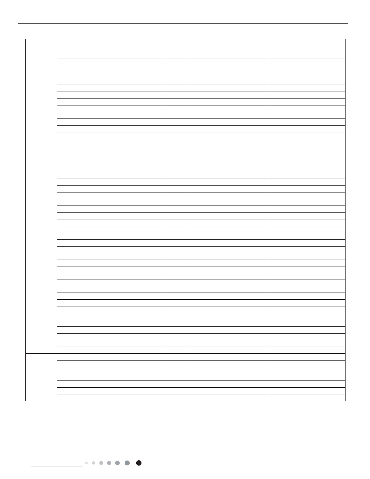
2. Specications
2.1 Specication Sheet
Model
GWC18MC-D3DNA3F
GWC18MC-D3DNA5F
Product Code
CB171008800
CB162009400
Power
Supply
Rated Voltage V
~
208/230
Rated Frequency Hz 60
Phases 1
Power Supply Mode Outdoor
Cooling Capacity(Min~Max) Btu/h 18000(5970~22350)
Heating Capacity(Min~Max) Btu/h /
Cooling Power Input(Min~Max) W 1500(300~2650)
Heating Power Input(Min~Max) W /
Cooling Current Input A 6.65
Heating Current Input A /
Rated Input W 2650
Rated Current A 11.76
Air Flow Volume (S/H/M/L) CFM 500/459/383/324
Dehumidifying Volume Pint/h 3.8
EER (Btu/h)/W 12
COP (Btu/h)/W /
SEER 18
HSPF /
Application Area yd2 32 2/7-50 1/4
Indoor Unit
Indoor Unit Model
GWC18MC-D3DNA3F/I
GWC18MC-D3DNA5F/I
Indoor Unit Product Code
CB171N08800
CB162N09400
Fan Type Cross-ow
Fan Diameter Length(DXL) inch Φ3 6/7X28
Cooling Speed(S/H/M/L) r/min 1500/1200/1050/900
Heating Speed(S/H/M/L) r/min /
Fan Motor Power Output W 20
Fan Motor RLA A 0.32
Fan Motor Capacitor μF 1.5
Evaporator Form W Aluminum Fin-copper Tube
Evaporator Pipe Diameter inch Φ2/7
Evaporator Row-n Gap inch 2-1/18
Evaporator Coil Length (LXDXW) inch 28 1/7X1X12
Swing Motor Model MP28VB
Swing Motor Power Output W 2.5
Fuse Current A 3.15
Sound Pressure Level (S/H/M/L) dB (A) 49/44/40/35
Sound Power Level (S/H/M/L) dB (A) 59/54/50/45
Dimension (WXHXD) inch 37X11 3/4X7 7/8
Dimension of Carton Box (LXWXH) inch 39 3/4X15X11 2/9
Dimension of Package (LXWXH) inch 39 7/8X15X11 4/5
Net Weight lb 24.3
Gross Weight lb 30.9
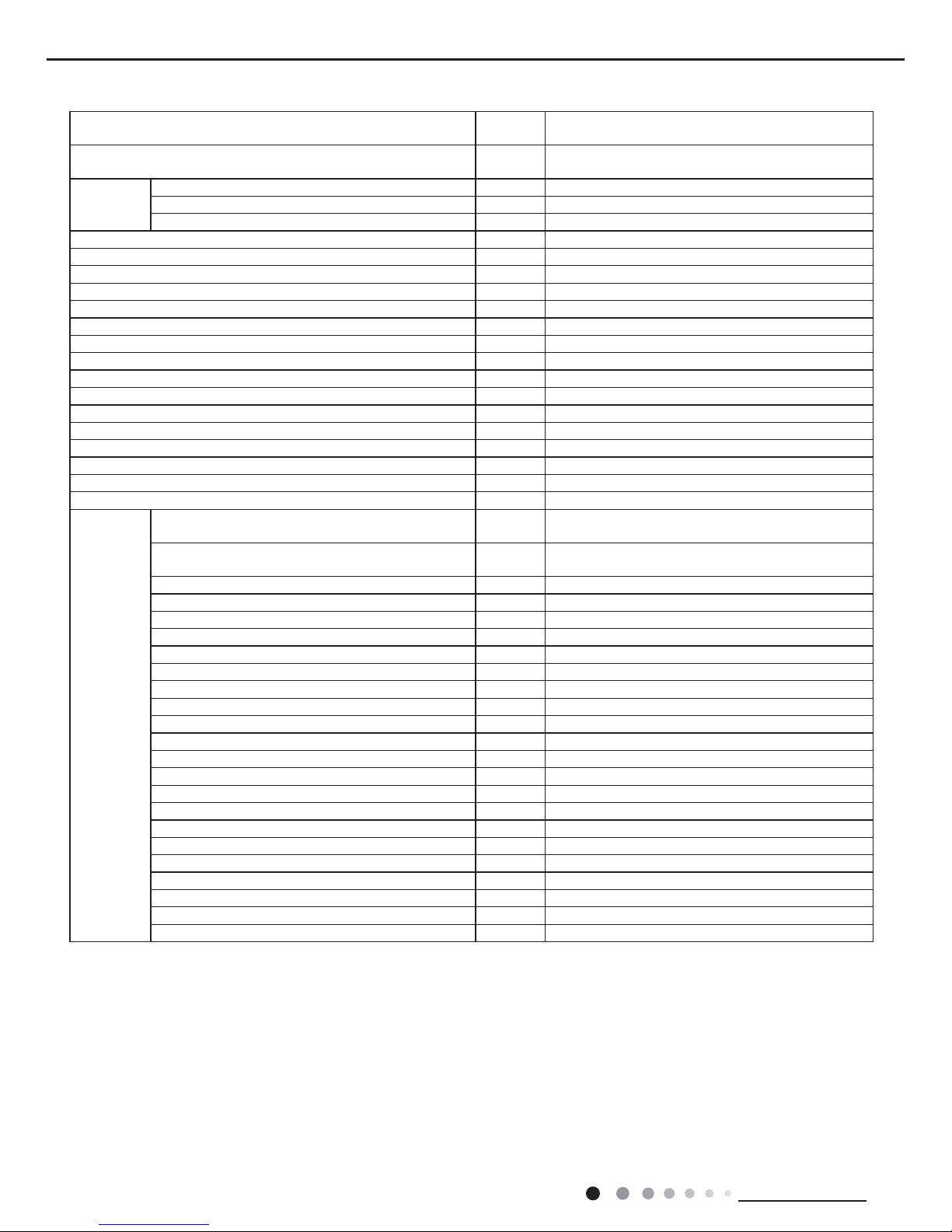
3
Technical Information
Service Manual
The above data is subject to change without notice. Please refer to the nameplate of the unit.
Outdoor Unit
Outdoor Unit Model GWC18MC-D3DNA3D/O
Outdoor Unit Product Code CB171W06800
Compressor Manufacturer
MITSUBISHI ELECTRIC (GUANGZHOU)
COMPRESSOR CO.,LTD
Compressor Model SNB130FGAMC
Compressor Oil FV50S/PVE
Compressor Type Rotary
Compressor LRA. A 13.8
Compressor RLA A 4.1
Compressor Power Input W 1200
Compressor Overload Protector INT11L-6578
Throttling Method Electron expansion valve
Set Temperature Range °F 61~86
Cooling Operation Ambient Temperature Range °F 19.4~109
Heating Operation Ambient Temperature Range °F /
Condenser Form Aluminum Fin-copper Tube
Condenser Pipe Diameter inch Φ2/7
Condenser Rows-n Gap inch 2-1/18
Condenser Coil Length (LXDXW) inch 33X1 1/2X26
Fan Motor Speed rpm 800
Fan Motor Power Output W 60
Fan Motor RLA A 0.28
Fan Motor Capacitor μF /
Outdoor Unit Air Flow Volume CFM 1883
Fan Type Axial-ow
Fan Diameter inch 20 1/2
Defrosting Method /
Climate Type T1
Isolation I
Moisture Protection IP24
Permissible Excessive Operating Pressure for the
Discharge Side
PSIG 550
Permissible Excessive Operating Pressure for the
Suction Side
PSIG 450
Sound Pressure Level (H/M/L) dB (A) 56/-/-
Sound Power Level (H/M/L) dB (A) 66/-/-
Dimension (WXHXD) inch 37 3/5X27 5/9X15 3/5
Dimension of Carton Box (LXWXH) inch 40 2/5X18X29
Dimension of Package (LXWXH) inch 40 1/2X18X29 1/2
Net Weight lb 99.2
Gross Weight lb 110.3
Refrigerant R410A
Refrigerant Charge oz 24 3/5
Connection
Pipe
Connection Pipe Length ft 24 3/5
Connection Pipe Gas Additional Charge oz/ft. 0.2
Outer Diameter Liquid Pipe inch 1/4
Outer Diameter Gas Pipe inch 1/2
Max Distance Height ft 32.8
Max Distance Length ft 82
Note: The connection pipe applies metric diameter.
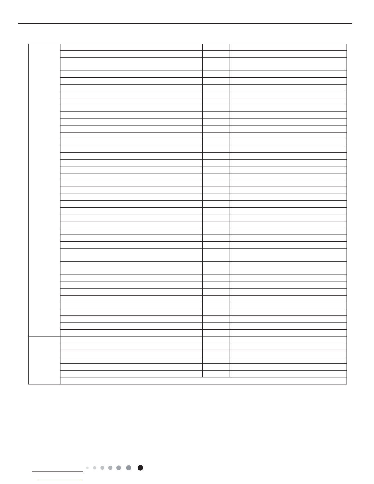
4
Technical Information
Service Manual
Model
GWH18MC-D3DNA3F
GWH18MC-D3DNA8F
GWH18MC-D3DNA3F
GWH18MC-D3DNA5F
Product Code
CB171008900
CB173004900
CB171008901
CB162009301
Power
Supply
Rated Voltage V
~
208/230 208/230
Rated Frequency Hz 60 60
Phases 1 1
Power Supply Mode Outdoor Outdoor
Cooling Capacity(Min~Max) Btu/h 18000(5970~22350) 18000(5970~22350)
Heating Capacity(Min~Max) Btu/h 19800(4100~22000) 19800(4100~22000)
Cooling Power Input(Min~Max) W 1500(300~2650) 1500(300~2650)
Heating Power Input(Min~Max) W 1650(335~2750) 1650(335~2750)
Cooling Current Input A 6.65 6.65
Heating Current Input A 7.32 7.32
Rated Input W 2750 2750
Rated Current A 12.20 12.20
Air Flow Volume (S/H/M/L) CFM 500/459/383/324 500/459/383/324
Dehumidifying Volume Pint/h 3.8 3.8
EER (Btu/h)/W 12 12
COP (Btu/h)/W 12 12
SEER 18 18
HSPF 10 10
Application Area yd2 32 2/7-50 1/4 32 2/7-50 1/4
Indoor Unit
Indoor Unit Model
GWH18MC-D3DNA3F/I
GWH18MC-D3DNA8F/I
GWH18MC-D3DNA3F/I
GWH18MC-D3DNA5F/I
Indoor Unit Product Code
CB171N08900
CB173N04900
CB171N08900
CB162N09300
Fan Type Cross-ow Cross-ow
Fan Diameter Length(DXL) inch Φ3 6/7X28 Φ3 6/7X28
Cooling Speed(S/H/M/L) r/min 1500/1200/1050/900 1500/1200/1050/900
Heating Speed(S/H/M/L) r/min 1500/1250/1150/1050 1500/1250/1150/1050
Fan Motor Power Output W 20 20
Fan Motor RLA A 0.32 0.32
Fan Motor Capacitor μF 1.5 1.5
Evaporator Form W Aluminum Fin-copper Tube Aluminum Fin-copper Tube
Evaporator Pipe Diameter inch Φ2/7 Φ2/7
Evaporator Row-n Gap inch 2-1/18 2-1/18
Evaporator Coil Length (LXDXW) inch 28 1/7X1X12 28 1/7X1X12
Swing Motor Model MP28VB MP28VB
Swing Motor Power Output W 2.5 2.5
Fuse Current A 3.15 3.15
Sound Pressure Level (S/H/M/L) dB (A) 49/44/40/35 49/44/40/35
Sound Power Level (S/H/M/L) dB (A) 59/54/50/45 59/54/50/45
Dimension (WXHXD) inch 37X11 3/4X7 7/8 37X11 3/4X7 7/8
Dimension of Carton Box (LXWXH) inch 39 3/4X15X11 2/9 39 3/4X15X11 2/9
Dimension of Package (LXWXH) inch 39 7/8X15X11 4/5 39 7/8X15X11 4/5
Net Weight lb 24.3 24.3
Gross Weight lb 30.9 30.9
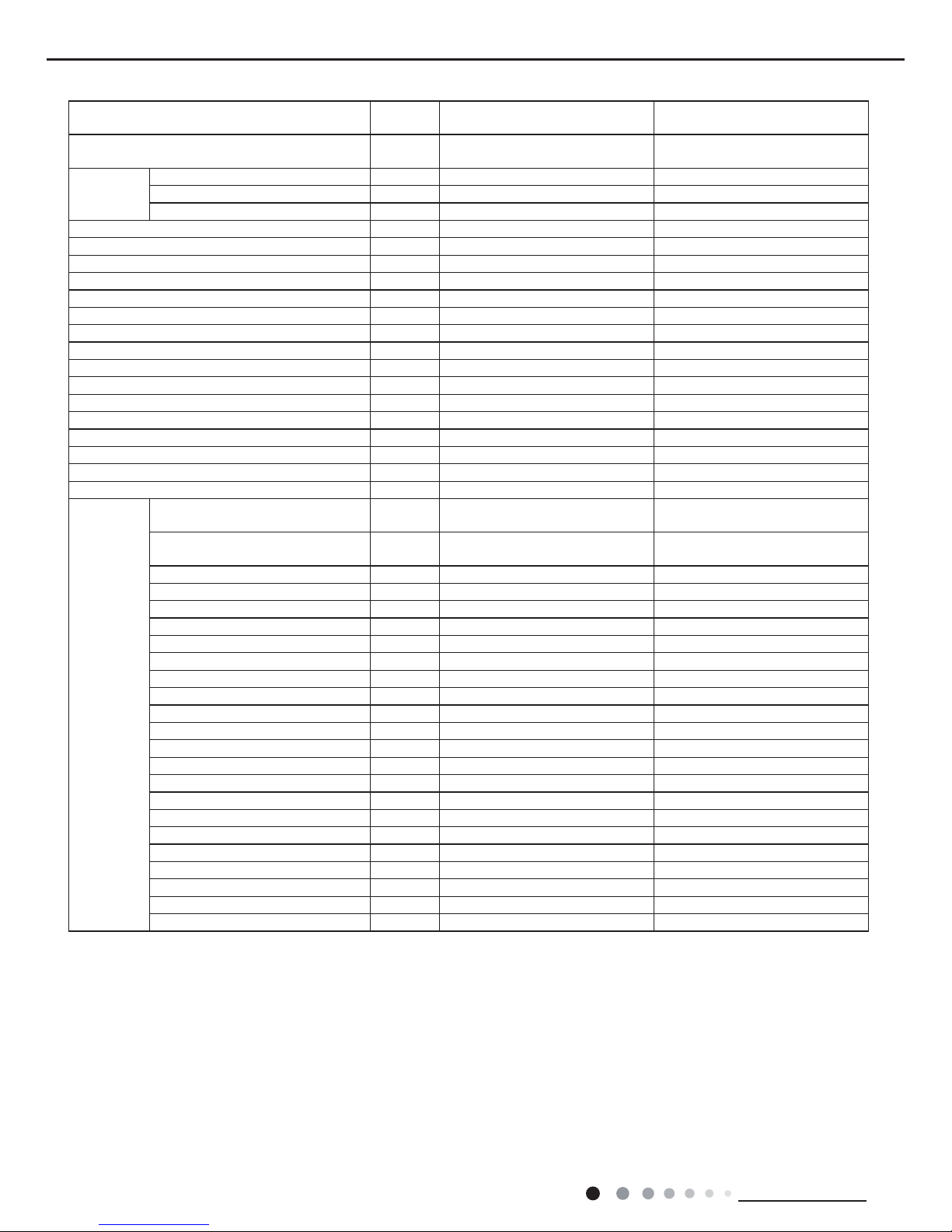
5
Technical Information
Service Manual
Outdoor Unit
Outdoor Unit Model GWH18MC-D3DNA3D/O
GWH18MC-D3DNA3D/O
(electric heating band)
Outdoor Unit Product Code CB171W04700 CB171W04701
Compressor Manufacturer
MITSUBISHI ELECTRIC
(GUANGZHOU) COMPRESSOR
CO.,LTD
MITSUBISHI ELECTRIC
(GUANGZHOU)
COMPRESSOR CO.,LTD
Compressor Model SNB130FGAMC SNB130FGAMC
Compressor Oil FV50S/PVE FV50S/PVE
Compressor Type Rotary Rotary
Compressor LRA. A 13.8 13.8
Compressor RLA A 4.1 4.1
Compressor Power Input W 1200 1200
Compressor Overload Protector INT11L-6578 INT11L-6578
Throttling Method Electron expansion valve Electron expansion valve
Set Temperature Range °F 61~86 61~86
Cooling Operation Ambient Temperature
Range
°F 19.4~109 19.4~109
Heating Operation Ambient Temperature
Range
°F 19.4~75.2 19.4~75.2
Condenser Form Aluminum Fin-copper Tube Aluminum Fin-copper Tube
Condenser Pipe Diameter inch Φ2/7 Φ2/7
Condenser Rows-n Gap inch 2-1/18 2-0.05
Condenser Coil Length (LXDXW) inch 33X1 1/2X26 33X1 1/2X26
Fan Motor Speed rpm 800 800
Fan Motor Power Output W 60 60
Fan Motor RLA A 0.28 0.28
Fan Motor Capacitor μF / /
Outdoor Unit Air Flow Volume CFM 1883 1883
Fan Type Axial-ow Axial-ow
Fan Diameter inch 20 1/2 20 1/2
Defrosting Method Automatic Defrosting Automatic Defrosting
Climate Type T1 T1
Isolation I I
Moisture Protection IP24 IP24
Permissible Excessive Operating Pressure
for the Discharge Side
PSIG 550 550
Permissible Excessive Operating Pressure
for the Suction Side
PSIG 450 450
Sound Pressure Level (H/M/L) dB (A) 56/-/- 56/-/-
Sound Power Level (H/M/L) dB (A) 66/-/- 66/-/-
Dimension (WXHXD) inch 37 3/5X27 5/9X15 3/5 37 3/5X27 5/9X15 3/5
Dimension of Carton Box (LXWXH) inch 40 2/5X18X29 40 2/5X18X29
Dimension of Package (LXWXH) inch 40 1/2X18X29 1/2 40 1/2X18X29 1/2
Net Weight lb 99.2 99.2
Gross Weight lb 110.3 110.3
Refrigerant R410A R410A
Refrigerant Charge oz 49.39 49.39
Connection
Pipe
Connection Pipe Length ft 24 3/5 24 3/5
Connection Pipe Gas Additional Charge oz/ft. 0.2 0.2
Outer Diameter Liquid Pipe inch 1/4 1/4
Outer Diameter Gas Pipe inch 1/2 1/2
Max Distance Height ft 33 33
Max Distance Length ft 82 82
Note: The connection pipe applies metric diameter.
The above data is subject to change without notice. Please refer to the nameplate of the unit.
6
Technical Information
Service Manual
Model
GWC24MD-D3DNA3F
GWC24MD-D3DNA5F
Product Code
CB171009700
CB162009600
Power
Supply
Rated Voltage V
~
208/230
Rated Frequency Hz 60
Phases 1
Power Supply Mode Outdoor
Cooling Capacity(Min~Max) Btu/h 21400(9600~25000)
Heating Capacity(Min~Max) Btu/h /
Cooling Power Input(Min~Max) W 1780(500~2650)
Heating Power Input(Min~Max) W /
Cooling Current Input A 7.9
Heating Current Input A /
Rated Input W 2650
Rated Current A 11.76
Air Flow Volume (S/H/M/L) CFM 500/459/383/324
Dehumidifying Volume Pint/h 5.28
EER (Btu/h)/W 12
COP (Btu/h)/W /
SEER 18
HSPF /
Application Area yd2 32 2/7-50 1/4
Indoor Unit
Indoor Unit Model
GWC24MD-D3DNA3F/I
GWC24MD-D3DNA5F/I
Indoor Unit Product Code
CB171N09700
CB162N09600
Fan Type Cross-ow
Fan Diameter Length(DXL) inch Φ3 6/7X30/1/8
Cooling Speed(S/H/M/L) r/min 1500/1200/1050/900
Heating Speed(S/H/M/L) r/min /
Fan Motor Power Output W 60
Fan Motor RLA A 0.24
Fan Motor Capacitor μF /
Evaporator Form W Aluminum Fin-copper Tube
Evaporator Pipe Diameter inch Φ2/7
Evaporator Row-n Gap inch 2-1/17
Evaporator Coil Length (LXDXW) inch 30 1/8X1X13 1/2
Swing Motor Model MP35XX
Swing Motor Power Output W 3
Fuse Current A 3.15
Sound Pressure Level (S/H/M/L) dB (A) 53/45/41/37
Sound Power Level (S/H/M/L) dB (A) 63/55/51/47
Dimension (WXHXD) inch 39 2/3X12 2/5X8 5/8
Dimension of Carton Box (LXWXH) inch 42 1/4X15 5/9X12 1/3
Dimension of Package (LXWXH) inch 42 1/3X15 2/3X12 21/23
Net Weight lb 29.8
Gross Weight lb 37.5
7
Technical Information
Service Manual
Outdoor Unit
Outdoor Unit Model GWC24MD-D3DNA3D/O
Outdoor Unit Product Code CB171W06900
Compressor Manufacturer
MITSUBISHI ELECTRIC (GUANGZHOU)
COMPRESSOR CO. LTD
Compressor Model SNB150FGAMC
Compressor Oil PVE/FV50S
Compressor Type Rotary
Compressor LRA. A 18.50
Compressor RLA A 4.90
Compressor Power Input W 1420
Compressor Overload Protector 1NT11L-6578
Throttling Method Electron expansion valve
Set Temperature Range °F 61~86
Cooling Operation Ambient Temperature Range °F 19.4~109
Heating Operation Ambient Temperature Range °F /
Condenser Form Aluminum Fin-copper Tube
Condenser Pipe Diameter inch Φ2/7
Condenser Rows-n Gap inch 2-1/18
Condenser Coil Length (LXDXW) inch 38X1 1/2X29 4/9
Fan Motor Speed rpm 800
Fan Motor Power Output W 90
Fan Motor RLA A 1.1
Fan Motor Capacitor μF 4
Outdoor Unit Air Flow Volume CFM 2354
Fan Type Axial-ow
Fan Diameter inch 20 3/4
Defrosting Method /
Climate Type T1
Isolation I
Moisture Protection IP24
Permissible Excessive Operating Pressure for the
Discharge Side
PSIG 550
Permissible Excessive Operating Pressure for the Suction
Side
PSIG 450
Sound Pressure Level (H/M/L) dB (A) 58/-/-
Sound Power Level (H/M/L) dB (A) 68/-/-
Dimension (WXHXD) inch 38 4/7X31 1/9X16 4/5
Dimension of Carton Box (LXWXH) inch 42 1/2X19X33
Dimension of Package (LXWXH) inch 42 2/3X19 1/5X33 2/3
Net Weight lb 119.1
Gross Weight lb 130.1
Refrigerant R410A
Refrigerant Charge oz 56.4
Connection
Pipe
Connection Pipe Length ft 24 3/5
Connection Pipe Gas Additional Charge oz/ft. 0.5
Outer Diameter Liquid Pipe inch 1/4
Outer Diameter Gas Pipe inch 5/8
Max Distance Height ft 32.8
Max Distance Length ft 82
Note: The connection pipe applies metric diameter.
The above data is subject to change without notice. Please refer to the nameplate of the unit.
8
Technical Information
Service Manual
Model
GWH24MD-D3DNA3F
GWH24MD-D3DNA5F
GWH24MD-D3DNA3F
GWH24MD-D3DNA8F
Product Code
CB171009801
CB162009501
CB171009800
CB173005000
Power
Supply
Rated Voltage V
~
208/230 208/230
Rated Frequency Hz 60 60
Phases 1 1
Power Supply Mode Outdoor Outdoor
Cooling Capacity(Min~Max) Btu/h 21400(9600~25000) 21400(9600~25000)
Heating Capacity(Min~Max) Btu/h 23000(4300~26000) 23000(4300~26000)
Cooling Power Input(Min~Max) W 1780(500~2650) 1780(500~2650)
Heating Power Input(Min~Max) W 2100(400~2750) 2100(400~2750)
Cooling Current Input A 7.9 7.9
Heating Current Input A 9.3 9.3
Rated Input W 2750 2750
Rated Current A 12.20 12.20
Air Flow Volume (S/H/M/L) CFM 589/471/412/353 589/471/412/353
Dehumidifying Volume Pint/h 5.28 5.28
EER (Btu/h)/W 12.0 12.0
COP (Btu/h)/W 10.6 10.6
SEER 18 18
HSPF 10 10
Application Area yd2 32 2/7-50 1/4 32 2/7-50 1/4
Indoor Unit
Indoor Unit Model
GWH24MD-D3DNA3F/I
GWH24MD-D3DNA5F/I
GWH24MD-D3DNA3F/I
GWH24MD-D3DNA8F/I
Indoor Unit Product Code
CB171N09800
CB162N09500
CB171N09800
CB173N05000
Fan Type Cross-ow Cross-ow
Fan Diameter Length(DXL) inch Φ3 6/7X30/1/8 Φ3 6/7X30/1/8
Cooling Speed(S/H/M/L) r/min 1500/1200/1050/900 1500/1200/1050/900
Heating Speed(S/H/M/L) r/min 1450/1150/1020/950 1450/1150/1020/950
Fan Motor Power Output W 60 60
Fan Motor RLA A 0.24 0.24
Fan Motor Capacitor μF / /
Evaporator Form W Aluminum Fin-copper Tube Aluminum Fin-copper Tube
Evaporator Pipe Diameter inch Φ2/7 Φ2/7
Evaporator Row-n Gap inch 2-1/17 2-1/17
Evaporator Coil Length (LXDXW) inch 30 1/8X1X13 1/2 30 1/8X1X13 1/2
Swing Motor Model MP35XX MP35XX
Swing Motor Power Output W 3 3
Fuse Current A 3.15 3.15
Sound Pressure Level (S/H/M/L) dB (A) 53/45/41/37 53/45/41/37
Sound Power Level (S/H/M/L) dB (A) 63/55/51/47 63/55/51/47
Dimension (WXHXD) inch 39 2/3X12 2/5X8 5/8 39 2/3X12 2/5X8 5/8
Dimension of Carton Box (LXWXH) inch 42 1/4X15 5/9X12 1/3 42 1/4X15 5/9X12 1/3
Dimension of Package (LXWXH) inch 42 1/3X15 2/3X12 21/23 42 1/3X15 2/3X12 21/23
Net Weight lb 29.8 29.8
Gross Weight lb 37.5 37.5
9
Technical Information
Service Manual
Outdoor Unit
Outdoor Unit Model
GWH24MD-D3DNA3D/O
(electric heating band)
GWH24MD-D3DNA3D/O
Outdoor Unit Product Code CB171W07001 CB171W07000
Compressor Manufacturer
MITSUBISHI ELECTRIC
(GUANGZHOU)COMPRESSOR
CO. LTD
MITSUBISHI ELECTRIC
(GUANGZHOU)COMPRESSOR
CO. LTD
Compressor Model SNB150FGAMC SNB150FGAMC
Compressor Oil PVE/FV50S PVE/FV50S
Compressor Type Rotary Rotary
Compressor LRA. A 18.50 18.50
Compressor RLA A 4.90 4.90
Compressor Power Input W 1420 1420
Compressor Overload Protector 1NT11L-6578 1NT11L-6578
Throttling Method Electron expansion valve Electron expansion valve
Set Temperature Range °F 61~86 61~86
Cooling Operation Ambient Temperature
Range
°F 19.4~109 19.4~109
Heating Operation Ambient Temperature
Range
°F 19.4~75.2 19.4~75.2
Condenser Form Aluminum Fin-copper Tube Aluminum Fin-copper Tube
Condenser Pipe Diameter inch Φ2/7 Φ2/7
Condenser Rows-n Gap inch 2-1/18 2-1/18
Condenser Coil Length (LXDXW) inch 38X1 1/2X29 4/9 38X1 1/2X29 4/9
Fan Motor Speed rpm 800 800
Fan Motor Power Output W 90 90
Fan Motor RLA A 1.1 0.5
Fan Motor Capacitor μF 4 /
Outdoor Unit Air Flow Volume CFM 2354 2354
Fan Type Axial-ow Axial-ow
Fan Diameter inch 20 3/4 Φ21 3/4
Defrosting Method / Automatic Defrosting
Climate Type T1 T1
Isolation I I
Moisture Protection IP24 IP24
Permissible Excessive Operating Pressure
for the Discharge Side
PSIG 550 550
Permissible Excessive Operating Pressure
for the Suction Side
PSIG 450 240
Sound Pressure Level (H/M/L) dB (A) 58/-/- 58/-/-
Sound Power Level (H/M/L) dB (A) 68/-/- 68/-/-
Dimension (WXHXD) inch 38 4/7X31 1/9X16 4/5 38 4/7X31 1/9X16 4/5
Dimension of Carton Box (LXWXH) inch 42 1/2X19X33 42 1/2X19X33
Dimension of Package (LXWXH) inch 42 2/3X19 1/5X33 2/3 42 2/3X19 1/5X33 2/3
Net Weight lb 132.3 123.3
Gross Weight lb 145.5 143.3
Refrigerant R410A R410A
Refrigerant Charge oz 56.4 56.4
Connection
Pipe
Connection Pipe Length ft 24 3/5 24 3/5
Connection Pipe Gas Additional Charge oz/ft. 0.5 0.5
Outer Diameter Liquid Pipe inch 1/4 1/4
Outer Diameter Gas Pipe inch 5/8 5/8
Max Distance Height ft 32.8 32.8
Max Distance Length ft 82 82
Note: The connection pipe applies metric diameter.
The above data is subject to change without notice. Please refer to the nameplate of the unit.
10
Technical Information
Service Manual
2.2 Operation Characteristic Curve
Cooling Heating
0 10 20 30 40 50 60 70 80 90 100 1200 10 20 30 40 50 60 70 90 11080
11
10
9
8
7
6
5
4
3
2
1
0
Compressor speed (rps)
)A( tnerruC
11
10
9
8
7
6
5
4
3
2
1
0
Compressor speed (rps)
)A( tnerruC
220V
230V
240V
220V
230V
240V
•Conditions cooling
Indoor DB 80˚F/WB 67˚F
Outdoor : DB 95˚F/WB75˚F
Indoor air flow : Turbo
Pipe length : 24 3/5 ft.
•Conditions heating
Indoor : DB 70˚F/WB 60˚F
Outdoor : DB 47˚F/WB 43˚F
Indoor air flow : Turbo
Pipe length : 24 3/5 ft.
2.3 Capacity Variation Ratio According to Temperature
100
105
95
90
85
80
75
70
65
60
55
50
Outdoor temp. (˚F)
)%( oitar yticapaC
Outdoor temp. (˚F)
)%( oitar yticapaC
Conditions cooling
Indoor: DB 80˚F/WB67˚F
Indoor air flow : Turbo
Pipe length: 24 3/5ft.
89.6 91.4 93.2 95 96.8 98.6 100.4 102.2 104 105.8 107.6 109.4
40
60
80
100
120
19 26.6 37.433.8 59.051.841.6 66.2 75.2
Conditions heating
Indoor: DB 70˚F
Indoor air flow : Turbo
Pipe length: 24 3/5ft.
Cooling Heating
0 10 20 30 40 50 60 70 80 90 100 1200 10 20 30 40 50 60 70 90 11080
11
10
9
8
7
6
5
4
3
2
1
0
Compressor speed (rps)
)A( tnerruC
11
10
9
8
7
6
5
4
3
2
1
0
Compressor speed (rps)
)A( tnerruC
220V
230V
240V
220V
230V
240V
•Conditions cooling
Indoor DB 80˚F/WB 67˚F
Outdoor : DB 95˚F/WB75˚F
Indoor air flow : Turbo
Pipe length : 24 3/5 ft.
•Conditions heating
Indoor : DB 70˚F/WB 60˚F
Outdoor : DB 47˚F/WB 43˚F
Indoor air flow : Turbo
Pipe length : 24 3/5 ft.
Cooling Heating
18K Unit
24K Unit
11
Technical Information
Service Manual
2.4 Cooling and Heating Data Sheet in Rated Frequency
Instruction:
T1: Inlet and outlet pipe temperature of evaporator
T2: Inlet and outlet pipe temperature of condenser
P: Pressure at the side of big valve
Connection pipe length: 24 3/5ft.
Cooling:
Heating:
2.5 Noise Curve
Rated cooling condition (°F)
(DB/WB)
Model
Pressure of gas pipe
connecting indoor
and outdoor unit
Inlet and outlet pipe
temperature of heat
exchanger
Fan speed
of indoor
unit
Fan speed
of outdoor
unit
Compressor
revolution (rps)
Indoor Outdoor P (MPa) T1 (°F) T2 (°F)
80/67 95/75 18K 0.9 to 1.1 53.6 to 57.2 109.4 to 105.8 Turbo High 77
80/67 95/75 24K 0.9 to 1.1 53.6 to 57.2 109.4 to 105.8 Turbo High 76
Rated heating condition (°F)
(DB/WB)
Model
Pressure of gas pipe
connecting indoor
and outdoor unit
Inlet and outlet pipe
temperature of heat
exchanger
Fan speed
of indoor
unit
Fan speed
of outdoor
unit
Compressor
revolution
(rps)
Indoor Outdoor P (MPa) T1 (°F) T2 (°F)
70/60 47/43 18K 2.2 to 2.4 100.4 to 98.6 35.6 to 39.2 Turbo High 80
70/60 47/43 24K 2.2 to 2.4 100.4 to 98.6 35.6 to 39.2 Turbo High 79
50
55
40
45
35
Indoor side noise
Indoor fan motor rotating speed
Compressor frequency/Hz
Low Middle High
Super High
60
50
40
30
20
0 20 40 60 100 80
Noise/dB(A)
Noise/dB(A)
Outdoor side noise
18K
24K
18K
24K
12
Technical Information
Service Manual
3. Outline Dimension Diagram
3.1 Indoor Unit
W
D
H
Unit:inch
2
Ф2 1/6
Ф2 1/6
3 1/3
3 1/2
6 2/7
2 5/9
Ф2 3/4 Ф2 3/4
5 1 2
27 1/3
27
7 2/3
7 1/4
18K Unit
24K Unit
Model W H D
18K 37 11 3/4 7 7/8
24K 39 2/3 12 2/5 8 5/8

13
Technical Information
Service Manual
3.2 Outdoor Unit
18K Unit
24K Unit
Unit:inch
14 4/7
31 1/9
16 4/5
15 5/9
38 4/7
24
36
Unit: inch
35
13 2/5
27 5/9
15 3/5
38
14 1/3
22
14
Technical Information
Service Manual
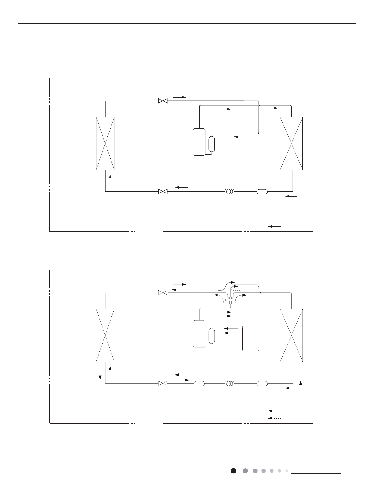
4. Refrigerant System Diagram
Refrigerant pipe diameter
Liquid pipe : 1/4" Gas pipe : 1/2"(18K)
Liquid pipe : 1/4" Gas pipe : 5/8"(24K)
Indoor unit
Outdoor unit
Indoor unit
Outdoor unit
COOLING
HEATING
Accumlator
4-Way valve
COOLING
Discharge
Suction
Discharge
Suction
Heat
exchanger
(evaporator)
Heat
exchanger
(evaporator)
Heat
exchanger
(condenser)
Valve
Valve
Valve
Valve
Liquid pipe
side
Gas pipe
side
Liquid pipe
side
Gas pipe
side
Compressor
Compressor
Strainer
Strainer Strainer
Capillary
Capillary
Accumlator
Heat
exchang
(condenser)
Cooling only model
Cooling and heating model
15
Technical Information
Service Manual
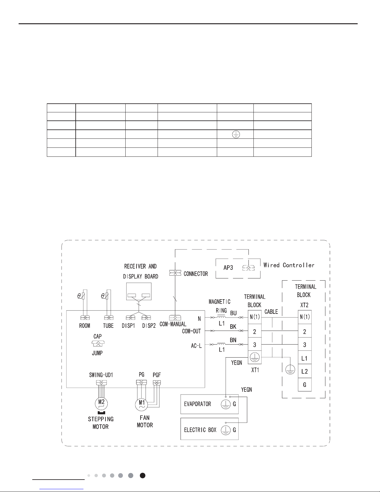
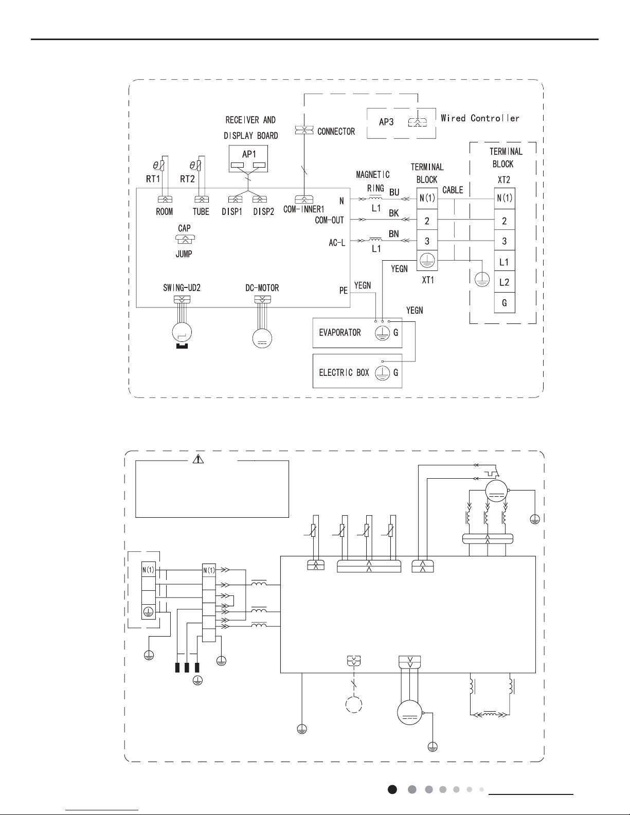
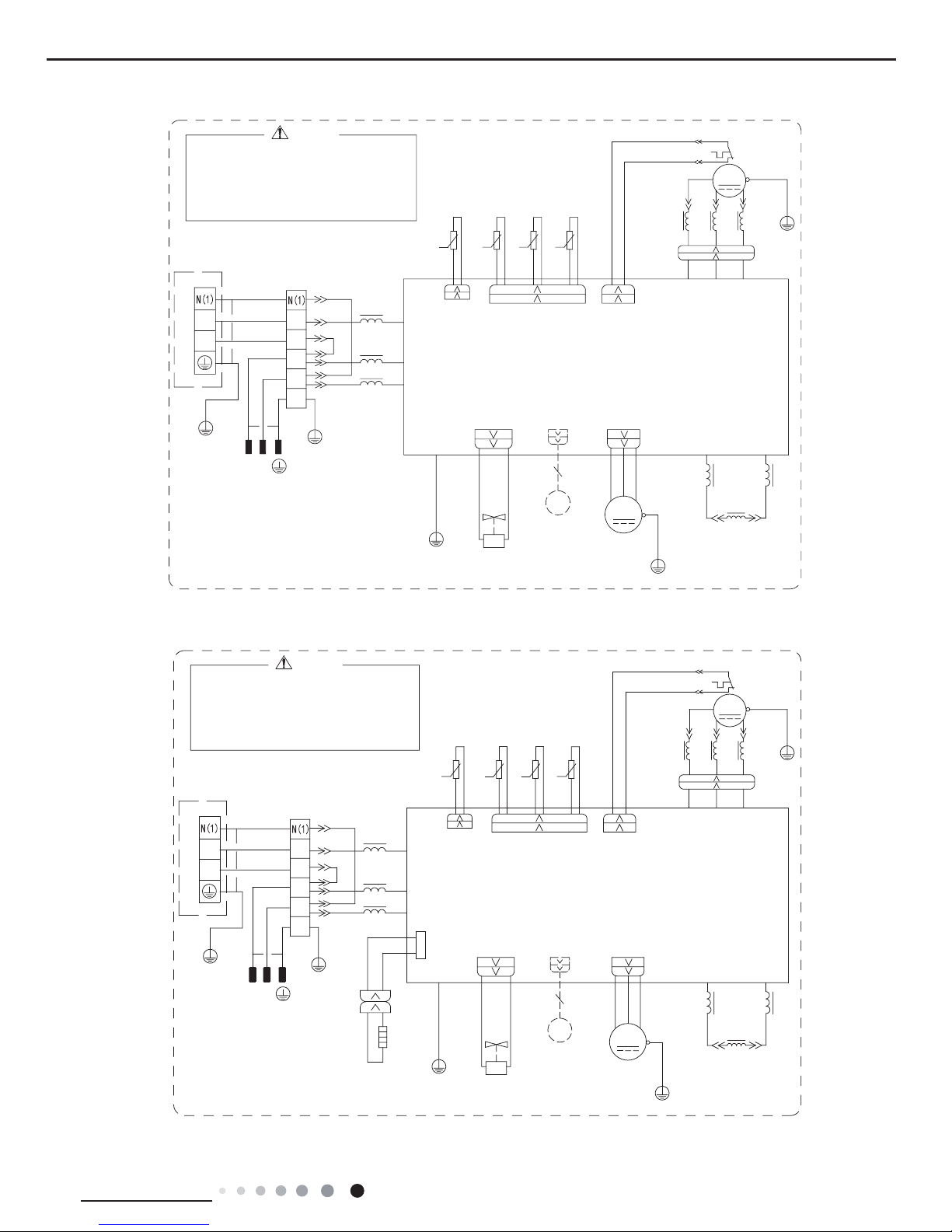
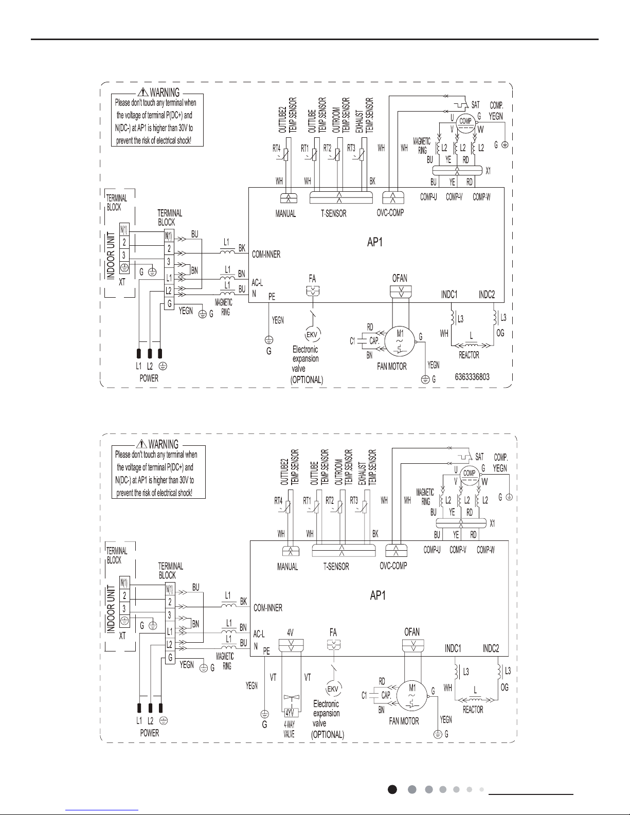
5. Electrical Part
5.1 Wiring Diagram
● Indoor Unit
●Instruction
Symbol Symbol Color Symbol Symbol Color Symbol Name
WH White GN Green CAP Jumper cap
YE Yellow BN Brown COMP Compressor
RD Red BU Blue Grounding wire
YEGN Yellow/Green BK Black / /
VT Violet OG Orange / /
Note: Jumper cap is used to determine fan speed and the swing angle of horizontal lover for this model.
$3
$30$,1%2$5'
57
57
7(036(1625
7(036(1625
78%(
5220
287'22581,7
GWC18MC-D3DNA3F/I GWC18MC-D3DNA5F/I GWH18MC-D3DNA3F/I GWH18MC-D3DNA8F/I GWH18MC-D3DNA5F/I
16
Technical Information
Service Manual
●Outdoor Unit
GWC18MC-D3DNA3D/O
5'%8 <(
*
<(*1
/
/
*
57 5757
5($&725
,1'&
2*
:+
,1'&
/
/
/
/ /
3(
5,1*
0$*1(7,&
5,1*
0$*1(7,&
/
/
:$51,1*
WKHYROWDJHRIWHUPLQDO3'&DQG
3OHDVHGRQWWRXFKDQ\WHUPLQDOZKHQ
SUHYHQWWKHULVNRIHOHFWULFDOVKRFN
1'&DW$3LVKLJKHUWKDQ9WR
//
*
3527(&72529(5/2$'
,1'22581,7
32:(5
*
%8
%1
/
/
;7
%.
%1
%8
76(1625
<(*1
$&/
1
&203:&2039&2038
8
9
:
*
*
&20,11(5
57
0
5'
*
2)$1
29&&203
:+:+
6$7
&203
;
&203
<(%8
:+ %.
7(036(1625
28778%(
2875220
7(036(1625
(;+$867
7(036(1625
<(*1
*
)$102725
7(50,1$/
%/2&.
(.9
)$
(OHFWURQLF
<(*1
:+
28778%(
7(036(1625
0$18$/
<(*1
H[SDQVLRQ
237,21$/
YDOYH
5,1*
0$*1(7,&
35,17('&,5&8,7%2$5'
$3
287'22581,7
02725
02725
0
0
5220
78%(
7(036(1625
7(036(1625
$30$,1%2$5'
)$1
67(33,1*
GWC24MD-D3DNA3F/I GWC24MD-D3DNA5F/I GWH24MD-D3DNA3F/I GWH24MD-D3DNA8F/I GWH24MD-D3DNA5F/I
17
Technical Information
Service Manual
GWH18MC-D3DNA3D/O(CB171W04700)
YDOYH
237,21$/
H[SDQVLRQ
<(*1
0$18$/
7(036(1625
28778%(
:+
<(*1
(OHFWURQLF
)$
(.9
:$<
%/2&.
7(50,1$/
)$102725
*
<(*1
7(036(1625
(;+$867
7(036(1625
2875220
28778%(
7(036(1625
%.:+
%8 <(
&203
;
<9
&203
6$7
:+ :+
29&&203
2)$1
*
5'
0
9
57
&20,11(5
*
*
:
9
8
&2038 &2039 &203:
1
$&/
<(*1
76(1625
%8
%1
%.
;7
/
/
%1
%8
*
32:(5
,1'22581,7
29(5/2$' 3527(&725
*
/ /
1'&DW$3LVKLJKHUWKDQ9WR
SUHYHQWWKHULVNRIHOHFWULFDOVKRFN
3OHDVHGRQWWRXFKDQ\WHUPLQDOZKHQ
WKHYROWDJHRIWHUPLQDO3'&DQG
:$51,1*
9$/9(
/
/
0$*1(7,&
5,1*
0$*1(7,&
5,1*
3(
//
97 97
/
/
/
,1'&
:+
2*
,1'&
5($&725
57 5757
*
/
/
<(*1
*
<(%8 5'
5,1*
0$*1(7,&
35,17('&,5&8,7%2$5'
$3
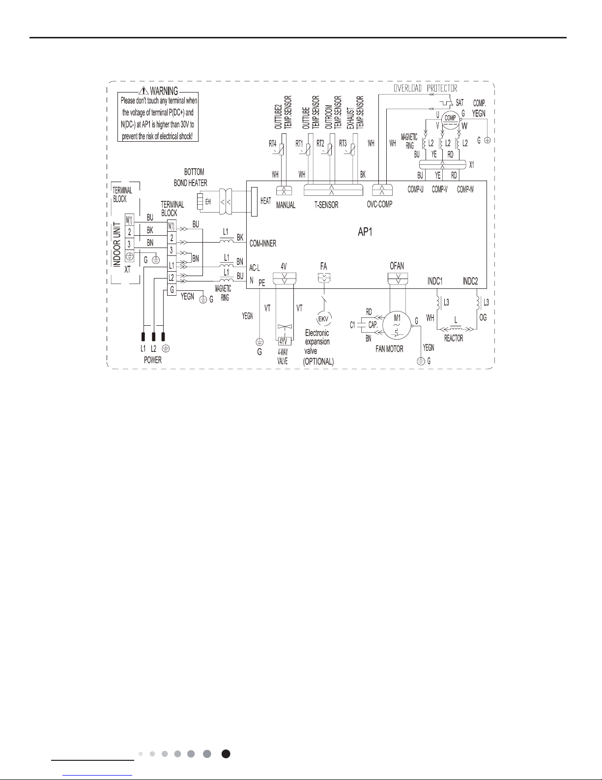
GWH18MC-D3DNA3D/O(electric heating band)(CB171W04701)
5'%8 <(
*
<(*1
/
/
*
5' 5'
(+
%27720
%21'+($7(5
+($7
57 5757
5($&725
,1'&
2*
:+
,1'&
/
/
/
9797
/ /
3(
5,1*
0$*1(7,&
5,1*
0$*1(7,&
/
/
9$/9(
:$51,1*
WKHYROWDJHRIWHUPLQDO3'&DQG
3OHDVHGRQWWRXFKDQ\WHUPLQDOZKHQ
SUHYHQWWKHULVNRIHOHFWULFDOVKRFN
1'&DW$3LVKLJKHUWKDQ9WR
//
*
3527(&72529(5/2$'
,1'22581,7
32:(5
*
%8
%1
/
/
;7
%.
%1
%8
76(1625
<(*1
$&/
1
&203:&2039&2038
8
9
:
*
*
&20,11(5
57
9
0
5'
*
2)$1
29&&203
:+:+
6$7
&203
<9
;
&203
<(%8
:+ %.
7(036(1625
28778%(
2875220
7(036(1625
(;+$867
7(036(1625
<(*1
*
)$102725
7(50,1$/
%/2&.
:$<
$3
(.9
)$
(OHFWURQLF
<(*1
:+
28778%(
7(036(1625
0$18$/
<(*1
H[SDQVLRQ
237,21$/
YDOYH
0$*1(7,&
5,1*
35,17('&,5&8,7%2$5'
18
Technical Information
Service Manual
0
0
0
0
OVERLOAD PROTECTOR
0
0
0
0
OVERLOAD PROTECTOR
GWH24MD-D3DNA3D/O(CB171W07000)
GWC24MD-D3DNA3D/O
19
Technical Information
Service Manual
These wiring diagrams are subject to change without notice; please refer to the one supplied with the unit.
0
0
0
0
GWH24MD-D3DNA3D/O(electric heating band)(CB171W07001)
20
Technical Information
Service Manual
1
2
3
4
5
6
7
8
9
10
11
12
13
14
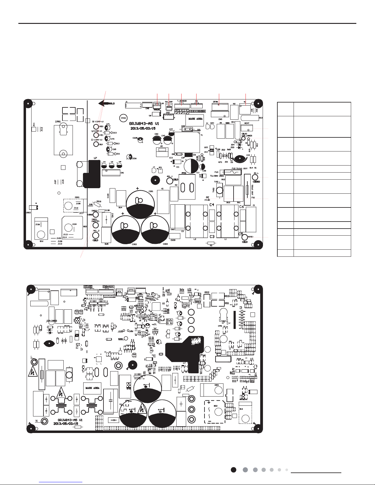
5.2 PCB Printed Diagram
1 Interface of PG motor
2
Up and down swing terminal
interface
3
Feedback interface of indoor
fan
4 Interface of display
5 Jumper cap
6 Wired controller
7
Tube temperature sensor
interface
8
Ambient temperature sensor
interface
9 Live wire interface
10 Neutral wire interface
11 Fuse
12 Fan capacitor
13 Auto button
14
Interface of indoor unit and
outdoor unit communication
● Top view
● Bottom view
Indoor Unit
GWC18MC-D3DNA3F/I GWC18MC-D3DNA5F/I GWH18MC-D3DNA3F/I GWH18MC-D3DNA8F/I GWH18MC-D3DNA5F/I
21
Technical Information
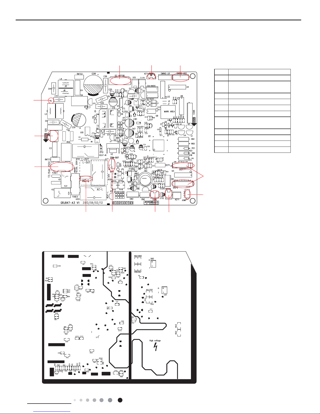
Service Manual
● Top view
● Bottom view
1 DC fan interface
2 Auto button
3
Up and down swing terminal
interface
4 Display terminal interface
5 Jumper cap
6 Ambient temp. sensor
7 Tube temp. sensor
8
IDU and ODU communication
interface
9 Live wire interface
10 Fuse
11 Neutral wire interface
12 Earth wire terminal interface
1 2 3
4
5
6789
10
11
12
GWC24MD-D3DNA3F/I GWC24MD-D3DNA5F/I GWH24MD-D3DNA3F/I GWH24MD-D3DNA8F/I GWH24MD-D3DNA5F/I
22
Technical Information
Service Manual
1 2 3 4 5 6 7
8
9
10
11
12
13
Outdoor Unit
● Top view
● Bottom view
1
Compressor wiring
connection terminal
2
ODU heat exchanger
middle copper pipe
temp. sensor terminal
3
Compressor overload
protection terminal
4
ODU temp. sensor
terminal
5 EXV terminal
6 Outdoor fan terminal
7
Four-way valve
terminal
8
Chassis electric heating
wiring terminal
9
Communication cable
with IDU
10 Power supply live wire
11 Earth wire
12
Power supply neutral
wire
13 PFC inductance wire
GWC18MC-D3DNA3D/O GWH18MC-D3DNA3D/O GWH18MC-D3DNA3D/O(electric heating band)
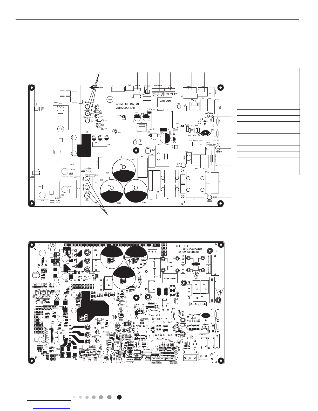
23
Technical Information
Service Manual
● Top view
GWC24MD-D3DNA3D/O GWH24MD-D3DNA3D/O GWH24MD-D3DNA3D/O(electric heating band)
1 2 3 4 5 6 7
8
9
10
11
12
● Bottom view
1
Compressor wiring
connection terminal
2
低温制冷感温包端子
3
Compressor overload
protection terminal
4
ODU temp. sensor
terminal
5 EXV terminal
6 Outdoor fan terminal
7
Four-way valve
terminal
8
Communication cable
with IDU
9 Power supply live wire
10 Earth wire
11
Power supply neutral
wire
12 PFC inductance wire
24
Technical Information
Service Manual
6. Function and Control
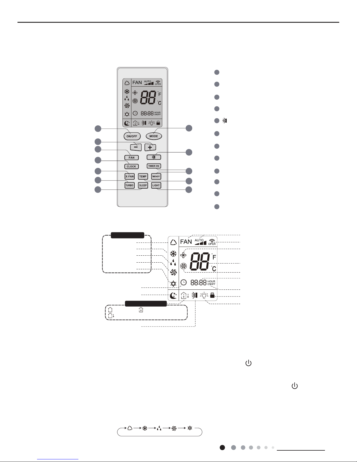
6.1 Remote Controller Introduction
Buttons on Remote Controller
Introduction for Icons on Display Screen
Introduction for Buttons on Remote Controller
Auto mode
Cool mode
Heat mode
Fan mode
Dry mode
Clock
Light
Child lock
TIMER ON/TIMER OFF
Up&down swing
:Indoor ambient temp.
:Set temp.
:Outdoor ambient temp.
Sleep mode
Set temperature
Send signal
Turbo mode
Set time
X-fan mode
Set fan speed
ON/OFF Button
2
3
1
5
6
4
8
9
7
11
12
10
MODE Button
+/- Button
FAN Button
TIMER ON/TIMER-OFF Button
X-FAN Button
TEMP Button
LIGHT Button
SLEEP Button
CLOCK Button
TURBO Button
Button
2
6
8
3
9
10
7
5
12
11
4
1
Operation mode
Temp. display type
1. ON/OFF Button
Press this button can turn on or turn off the air conditioner. After turning on the air conditioner, operation indicator " " on indoor
unit’s display is ON (green indicator. The colour is different for different models), and indoor unit will give out a sound.
2. MODE Button
Press this button to select your required operation mode.
Note:After putting through the power, the air conditioner will give out a sound. Operation indictor " " is ON (red indicator). After that,
you can operate the air conditioner by using remote controller.
AUTO COOL DRY FAN HEAT
Operation mode
Temp. display type
25
Technical Information
Service Manual
4. FAN Button
Pressing this button can set fan speed circularly as: auto (AUTO), low( ) ,medium( ),high( ).
Note:
● Under AUTO speed, the IDU fan motor will adjust the fan speed (high, medium or low speed) according to ambient temperature.
● Fan speed under dry mode is low speed.
● When selecting auto mode, Air conditioner will start auto operation according to indoor ambient temperature.Set temperature can’t be
adjusted and will not be displayed as well. Press "FAN" button can adjust fan speed. Press " " button can adjust fan blowing angle.
● After selecting cool mode, air conditioner will operate under cool mode. Cool indicator " " on indoor unit is ON. Press "+" or "-" button
to adjust set temperature. Press "FAN" button to adjust fan speed. Press " " button to adjust fan blowing angle.
● When selecting dry mode, the air conditioner operates at low speed under dry mode. Dry indicator " " on indoor unit is ON. Under dry
mode, fan speed can’t be adjusted. Press " " button to adjust fan blowing angle.
● When selecting fan mode, the air conditioner will only blow fan, no cooling and no heating.All indicators are OFF.Operation indicator is
ON.Press "FAN" button to adjust fan speed. Press " " button to adjust fan blowing angle.
● When selecting heating mode, the air conditioner operates under heat mode. Heat indicator " " on indoor unit is ON. Press “+” or “-“
button to adjust set temperature Press “FAN” button to adjust fan speed. Press " " button to adjust fan blowing angle.(Cooling only unit
won’t receive heating mode signal. If setting heat mode with remote controller, press ON/OFF button can’t start up the unit).
Note:
● For preventing cold air, after starting up heating mode, indoor unit will delay 1~5minutes to blow air (actual delay time is depend on
indoor ambient temperature).
● Set temperature range from remote controller: 60.8~86℉ ; Fan speed: auto, low speed,medium speed, high speed.
3. “+” or“-” Button
● Press “+” or “-“ button once increase or decrease set temperature 33.8℉.Holding "+" or "-" button, 2s later, set temperature on remote
controller will change quickly. On releasing button after setting is nished, temperature indicator on indoor unit will change accordingly.
(Temperature can’t be adjusted under auto mode)
● When setting TIMER ON, TIMER OFF or CLOCK, press “+” or “-“ button to adjust time.(Refer to CLOCK, TIMER ON, TIMER OFF
buttons)
6. CLOCK Button
Press this button to set clock time. " " icon on remote controller will blink. Pess "+" or "-" button within 5s to set clock time. Each
pressing of "+" or "-" button, clock time will increase or decrease 1 minute. Hold "+" or "-" button, 2s later, time will change quickly.
Release this button when reaching your required time. Press “CLOCK" button to conrm the time. " " icon stops blinking.
Note:
● Clock time adopts 24-hour mode.
● The interval between two operation can’t exceeds 5s. Otherwise, remote controller will quit setting status. Operation for TIMER
ON/TIMER OFF is the same.
7. TIMER-ON/TIMER-OFF Button
● TIMER ON button
TIMER ON button
“TIMER ON” button can set the time for timer on. After pressing this button, " " icon disappears and the word “ON" on remote
5. Button
Pressing this button can select up&down swing angle. Fan blow angle can be selected circularly as below:
● When selecting " " , air conditioner is blowing fan automatically. Horizontal louver will automatically swing up & down at
maximum angle.
● When selecting "
、 、 、 、
", air conditioner is blowing fan at fixed position. Horizontal louver will stop at the fixed
position.
● When selecting "
、、
”, air conditioner is blowing fan at xed angle. Horizontal louver will send air at the xed angle.
● Hold " " button above 2s to set your required swing angle. When reaching your required angle, release the button.
Note:
"
、、
" may not be available. When air conditioner receives this signal, the air conditioner will blow fan automatically.
Auto
(horizontal louvers
stops at current position)
no display

26
Technical Information
Service Manual
controller blinks. Press "+" or "-"button to adjust TIMER ON setting. After each pressing "+" or "-"button, TIMER ON setting will increase
or decrease 1min. Hold "+" or "-"button, 2s later, the time will change quickly
until reaching your required time. Press “ TIMER ON”to conrm it. The word “ON" will stop blinking. " " icon resumes displaying.
Cancel TIMER ON: Under the condition that TIMER ON is started up, press “TIMER ON” button to cancel it.
● TIMER OFF button
"TIMER OFF" button can set the time for timer off. After pressing this button, " " icon disappears and the word "OFF" on remote
controller blinks. Press "+" or "-" button to adjust TIMER OFF setting. After each pressing "+" or "-" button, TIMER OFF setting will
increase or decrease 1min. Hold "+" or "-" button, 2s later, the time will change
quickly until reaching your required time. Press "TIMER OFF" to confirm it .The word "OFF"will stop blinking " " icon resumes
displaying. Cancel TIMER OFF. Under the condition that TIMER OFF is started up, press “TIMER OFF” button to cancel it.
Note:
● Under on and off status, you can set TIMER OFF or TIMER on simultaneously.
● Before setting TIMER ON or TIMER OFF, please adjust the clock time.
● After starting up TIMER ON or TIMER OFF, set the constant circulating valid. After that, air conditioner will be turned on or turned off
according to setting time. ON/OFF button has no effect on setting. If you don’t need this function, please use remote controller to cancel
it.
8. X-FAN Button
Press this button under cool and dry mode to start up x-fan function, and " " icon on remote controller will be displayed. Press this
button again to cancel x-fan function, and " "icon will disappear.
Note:
● When x-fan function is on, if the air conditioner is turned off, indoor fan will still operate at low speed for a while to blow the residual
water inside the air duct.
● During x-fan operation, press X-FAN button to turn off x-fan function. Indoor fan will stop operation immediately.
9. TEMP Button
By pressing this button, you can see indoor set temperature, indoor ambient temperature or outdoor ambient temperature on indoor
unit’s display. The setting on remote controlleris selected circularly as below:
When selecting " " or no display with remote controller, temperature indicator on indoor unit displays set temperature;
When selecting " " with remote controller, temperature indicator on indoor unit displays indoor ambient temperature;
When selecting " " with remote controller, temperature indicator on indoor unit displays outdoor ambient temperature.
Note:
● Outdoor temperature display is not available for some models. At that time, indoor unit receives" " signal, while it displays
indoor set temperature.
● It’s defaulted to display set temperature when turning on the unit.There is no display in the remote controller.
● Only for the models whose indoor unit has dual-8 display
10. TURBO Button
Under COOL or HEAT mode, press this button to turn to quick COOL or quick HEAT mode. " " icon is displayed on remote
controller. Press this button again to exit turbo function and " " icon will disappear.
11. SLEEP Button
Under COOL, HEAT mode, press this button to start up sleep function. " " icon is displayed on remote controller. Press this button
again to cancel sleep function and " " icon will disappear.
12. LIGHT Button
Press this button to turn off display light on indoor unit. " " icon on remote controller disappears. Press this button again to turn
on display light. " " icon is displayed.
Child lock function:
Press "+"and "-" simultaneously to turn on or turn off child lock function. When child lock function is on, " " icon is displayed on
remote controller. If you operate the remote controller, it won’t send signal.
Temperature display switchover function:
Under OFF status, press "-" and "MODE" buttons simultaneously to switch temperature display between ℃ and ℉.
no display
Function Introduction for Combination Buttons
27
Technical Information
Service Manual
Note:
● During operation, point the remote control signal sender at the receiving window
on indoor unit.
● The distance between signal sender and receiving window should be no more than
8m, and there should be no obstacles between them.
● Signal may be interfered easily in the room where there is fluorescent lamp or
wireless telephone; remote controller should be close to indoor unit during operation.
● Replace new batteries of the same model when replacement is required.
● When you don’t use remote controller for a long time, please take out the batteries.
● If the display on remote controller is fuzzy or there’s no display, please replace
batteries.
Signal sender
Battery
Cover of
battery box
Remove
Reinstall
1. After putting through the power, press “ON/OFF” button on remote controller to turn on
the air conditioner.
2. Press "MODE" button to select your required mode:AUTO,COOL,DRY,FAN,HEAT.
3. Press “+” or “-“ button to set your required temperature. (Temperature can’t be
adjusted under auto mode).
4. Press ‘FAN” button to set your required fan speed: auto, low, medium and high speed.
5. Press " " button to select fan blowing angle.
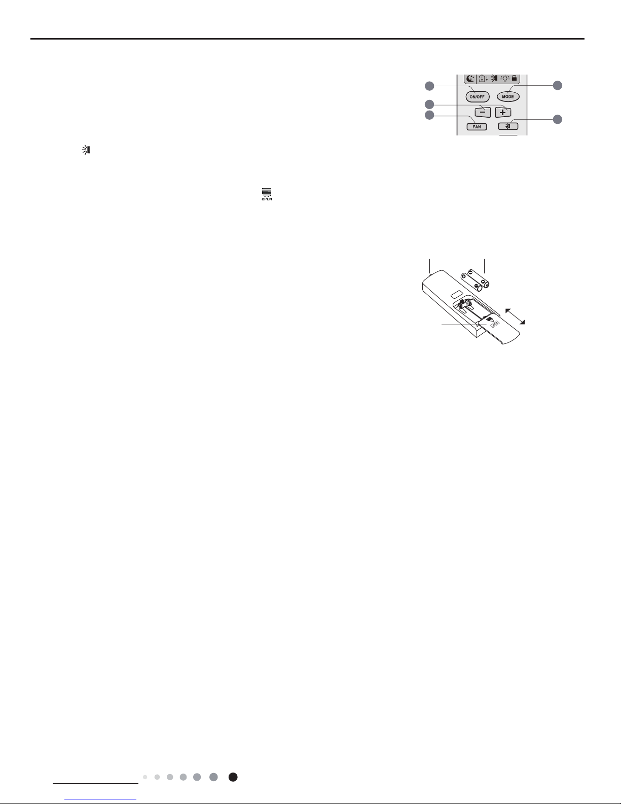
1.Press the back side of remote controller marked with“ ”as shown in the g, and then push out the cover
of battery box along the arrow direction.
2. Replace two 7# (AAA 1.5V) dry batteries, and make sure the position of “+” polar and “-“ polar are correct.
3. Reinstall the cover of battery box.
Operation Guide
Replacement of Batteries in Remote Controller
2
3
5
4
1
 Loading...