

Gree GWH18AAD-K6DNA1B/I, GWH18AAD-K6DNA5A/I, GWH24AAD-K6DNA1A/I, GWH24AAD-K6DNA5A/I, GWH18AAD-K6DNA5B/I Service Manual
...
Service Manual
Change for life
GREE ELECTRIC APPLIANCES, INC. OF ZHUHAI

Service Manual
Table of Contents
Part
Ⅰ
: Technical Information
.......................................................................1
1. Summary
......................................................................................................................1
2. Specications
..........................................................................................................3
2.1 Specication Sheet ...........................................................................................................3
2.2 Operation Characteristic Curve ...................................................................................... 11
2.2 Capacity Curve in Different Outdoor Temperature .........................................................11
2.3 Cooling and Heating Data Sheet in Rated Frequency ...................................................11
2.5 Noise Curve ....................................................................................................................12
3. Outline Dimension Diagram
......................................................................13
3.1 Indoor Unit ......................................................................................................................13
3.2 Outdoor Unit ...................................................................................................................14
4. Refrigerant System Diagram
....................................................................16
5. Electrical Part
.........................................................................................................17
5.1 Wiring Diagram ...............................................................................................................17
5.2 PCB Printed Diagram .....................................................................................................20
6. Function and Control
......................................................................................23
6.1 Remote Controller Introduction .....................................................................................23
6.2 GREE+ App Operation Manual ......................................................................................27
6.3 Ewpe Smart App Operation Manual ...............................................................................28
6.4 Brief Description of Modes and Functions ......................................................................29
Part
Ⅱ
: Installation and Maintenance
.................................................38
7. Notes for Installation and Maintenance
..........................................38
8. Installation
................................................................................................................42
8.1 Installation Dimension Diagram ......................................................................................42
8.2 Installation Parts-checking ............................................................................................44
8.3 Selection of Installation Location ....................................................................................44
8.4 Electric Connection Requirement ...................................................................................44
8.5 Installation of Indoor Unit ................................................................................................44
8.6 Installation of Outdoor unit .............................................................................................47
8.7 Vacuum Pumping and Leak Detection ...........................................................................48
8.8 Check after Installation and Test operation ....................................................................48
Table of Contents

Service Manual
9. Maintenance
............................................................................................................49
9.1 Malfunction Display of Indoor Unit ..................................................................................49
9.2 Procedure of Troubleshooting ........................................................................................51
9.3 Maintenance method for normal malfunction .................................................................68
10. Exploded View and Parts List
..............................................................70
10.1 Indoor Unit ....................................................................................................................70
10.2 Outdoor Unit .................................................................................................................80
11. Removal Procedure
.......................................................................................88
11.1 Removal Procedure of Indoor Unit ...............................................................................88
11.2 Removal Procedure of Outdoor Unit ............................................................................93
Appendix:
......................................................................................................................113
Appendix 1: Reference Sheet of Celsius and Fahrenheit ..................................................113
Appendix 2: Conguration of Connection Pipe ...................................................................113
Appendix 3: Pipe Expanding Method .................................................................................114
Appendix 4: List of Resistance for Temperature Sensor ....................................................115
Table of Contents
1
Technical Information
Service Manual
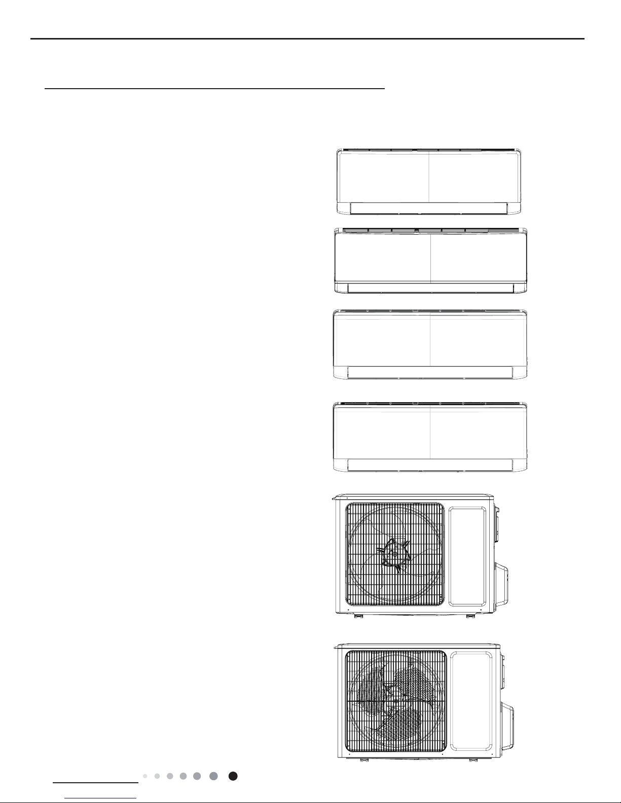
1. Summary
Indoor Unit:
GWH18AAD-K6DNA1B/I
GWH18AAD-K6DNA1A/I
GWH24AAD-K6DNA1A/I
Part
Ⅰ
: Technical Information
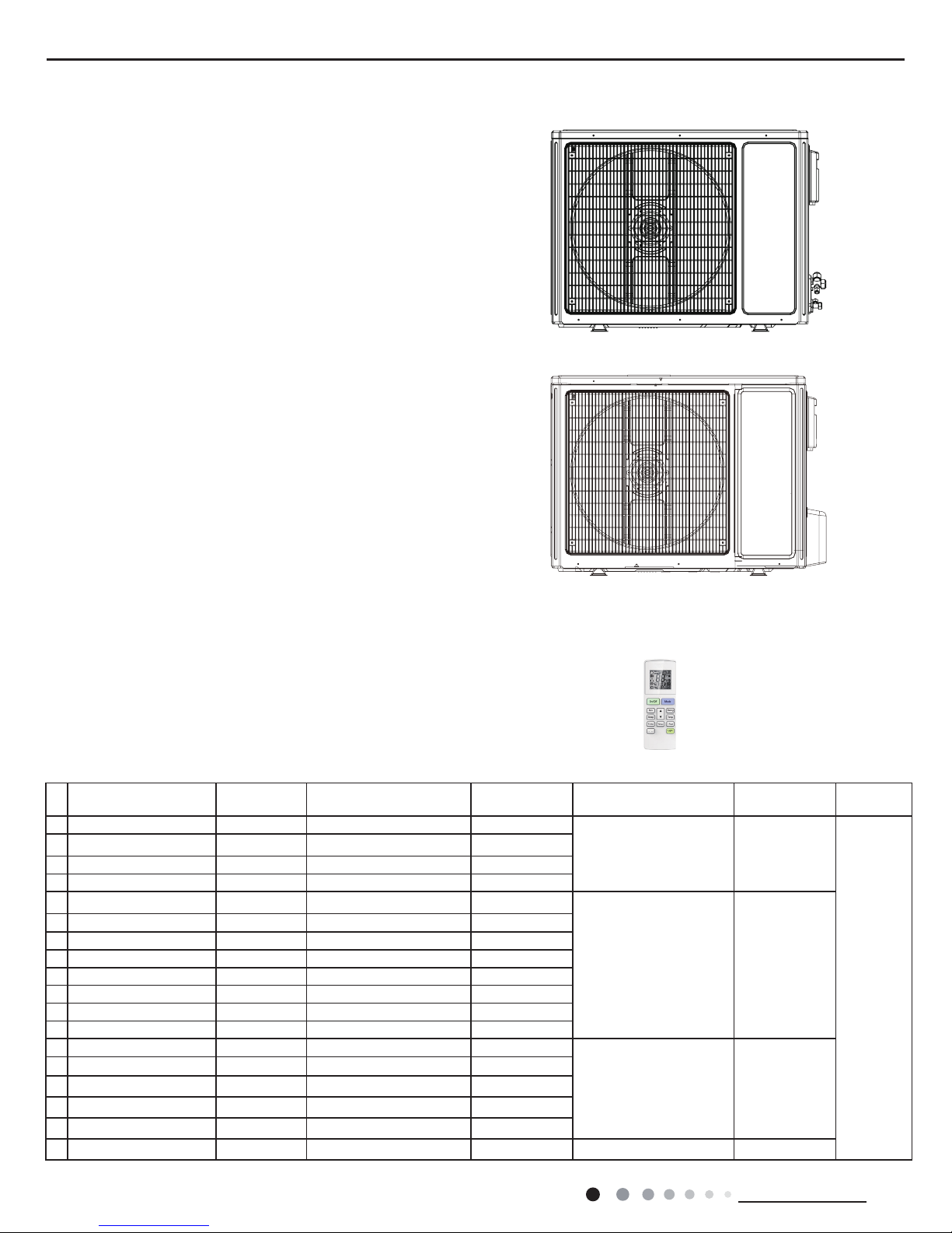
Outdoor Unit:
GWH18AAD-K6DNA1A/O
GWH18AAD-K6DNA1B/O
GWH24AAD-K6DNA5A/I
GWH18AAD-K6DNA5A/I
GWH18AAD-K6DNA5B/I
GWH18AAD-K6DNA4A/I
GWH18AAD-K6DNA4B/I
GWH24AAE-K6DNA4C/I
GWH24AAD-K6DNA4A/I
GWH18AAD-K6DNA2A/I
GWH24AAD-K6DNA2A/I
2
Technical Information
Service Manual
GWH24AAD-K6DNA1A/O
GWH24QE-K6DNA1C/O
Remote Controller:
YAW1F5(WiFi)
WiFi
Model List:
No Model Product code Indoor model
Indoor product
code
Outdoor model
Outdoor product
code
Remote
Controller
1
GWH18AAD-K6DNA1A CB476000200 GWH18AAD-K6DNA1A/I CB476N00200
GWH18AAD-K6DNA1A/O CB476W00200
YAW1F5
(WiFi)
2 GWH18AAD-K6DNA1A CB476000201 GWH18AAD-K6DNA1A/I CB476N00201
3 GWH18AAD-K6DNA5A CB488000700 GWH18AAD-K6DNA5A/I CB488N00700
4 GWH18AAD-K6DNA2A CB477001300 GWH18AAD-K6DNA2A/I CB477N01300
5 GWH18AAD-K6DNA4A CB479000600 GWH18AAD-K6DNA4A/I CB479N00600
GWH24AAD-K6DNA1A/O CB476W00100
6
GWH24AAD-K6DNA1A CB476000100 GWH24AAD-K6DNA1A/I CB476N00100
7 GWH24AAD-K6DNA1A CB476000101 GWH24AAD-K6DNA1A/I CB476N00101
8 GWH24AAD-K6DNA5A CB488000500 GWH24AAD-K6DNA5A/I CB488N00500
9 GWH24AAD-K6DNA4A CB479000900 GWH24AAD-K6DNA4A/I CB479N00900
10 GWH24AAD-K6DNA4A CB479000901 GWH24AAD-K6DNA4A/I CB479N00901
11 GWH24AAD-K6DNA5A CB488000501 GWH24AAD-K6DNA5A/I CB488N00501
12 GWH24AAD-K6DNA2A CB477001400 GWH24AAD-K6DNA2A/I CB477N01400
13 GWH18AAD-K6DNA1B CB476000600 GWH18AAD-K6DNA1B/I CB476N00600
GWH18AAD-K6DNA1B/O CB476W00600
14 GWH18AAD-K6DNA5B CB488000600 GWH18AAD-K6DNA5B/I CB488N00600
15 GWH18AAD-K6DNA4B CB479001300 GWH18AAD-K6DNA4B/I CB479N01300
16 GWH18AAD-K6DNA4B CB479001301 GWH18AAD-K6DNA4B/I CB479N013001
17 GWH18AAD-K6DNA5B CB488000601 GWH18AAD-K6DNA5B/I CB488N00601
18 GWH24AAE-K6DNA4C CB479000700 GWH24AAE-K6DNA4C/I CB479N00700 GWH24QE-K6DNA1C/O CB419W12200
3
Technical Information
Service Manual
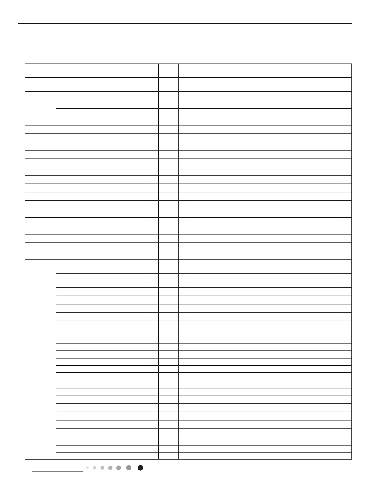
2. Specications
2.1 Specication Sheet
Model
1.GWH18AAD-K6DNA1A 2.GWH18AAD-K6DNA5A
3.GWH18AAD-K6DNA4A 4.GWH18AAD-K6DNA2A
Product Code
1.CB476000200/CB476000201 2. CB488000700
3.CB479000600 4.CB477001300
Power
Supply
Rated Voltage V~ 220-240
Rated Frequency Hz 50
Phases 1
Power Supply Mode Outdoor
Cooling Capacity W 5130
Heating Capacity W 5280
Cooling Power Input W 1600
Heating Power Input W 1450
Cooling Power Current A 7.0
Heating Power Current A 6.3
Rated Input W 2300
Rated Current A 10.8
Rated Heating Current A 12
Air Flow Volume(SH/H/M/L/SL) m3/h 850/720/610/520/-
Dehumidifying Volume L/h 1.8
EER W/W 3.21
COP W/W 3.64
SEER W/W 6.1
HSPF W/W /
Application Area m
2
23-34
Indoor Unit
Model of Indoor Unit
1.GWH18AAD-K6DNA1A/I 2.GWH18AAD-K6DNA5A/I
3. GWH18AAD-K6DNA4A/I 4.GWH18AAD-K6DNA2A/I
Product Code of Indoor Unit
1.CB476N00200/CB476N00201 2.CB488N00700
3.CB479N00600 4. CB477N01300
Fan Type Cross-ow
Diameter Length(DXL) mm Φ106X706
Fan Motor Cooling Speed(SH/H/M/L/SL) r/min 1230/1130/1030/800/-
Fan Motor Heating Speed(SH/H/M/L/SL) r/min 1350/1200/1050/900/Output of Fan Motor W 35
Fan Motor RLA A 0.35
Fan Motor Capacitor μF 2.5
Input of Heater W /
Evaporator Form Aluminum Fin-copper Tube
Pipe Diameter mm Ф7
Row-n Gap mm 2-1.4
Coil Length (LXDXW) mm 715X25.4X304.8
Swing Motor Model MP35CP
Output of Swing Motor W 2.5
Fuse A 3.15
Sound Pressure Level (SH/H/M/L/SL) dB (A) 48/44/39/34/-
Sound Power Level (SH/H/M/L/SL) dB (A) 58/54/49/44/-
Dimension (WXHXD) mm 970X300X225
Dimension of Carton Box (LXWXH) mm 1017X366X285
Dimension of Package (LXWXH) mm 1020X369X295
Net Weight kg 13.5
Gross Weight kg 16.5

4
Technical Information
Service Manual
The above data is subject to change without notice; please refer to the nameplate of the unit.
Outdoor Unit
Model of Outdoor Unit GWH18AAD-K6DNA1A/O
Product Code of Outdoor Unit CB476W00200
Compressor Manufacturer/Trademark ZHUHAI LANDA COMPRESSOR CO.,LTD
Compressor Model QXF-B141ZF030A
Compressor Oil 68DA
Compressor Type Rotary
L.R.A. A 25
Compressor RLA A 6.5
Compressor Power Input W 1410
Overload Protector 1NT11L-6233/KSD115oC/HPC 115/95
Throttling Method Electron expansion valve
Operation Temp
o
C 16~30
Ambient Temp (Cooling)
o
C -15~43
Ambient Temp (Heating)
o
C -15~24
Condenser Form Aluminum Fin-copper Tube
Pipe Diameter mm Φ7.94
Rows-n Gap mm 2-1.4
Coil Length (LXDXW)
mm
742X38.1X550
Fan Motor Speed rpm 780
Output of Fan Motor W 40
Fan Motor RLA
A 0.62
Fan Motor Capacitor μF /
Air Flow Volume of Outdoor Unit m3/h 2400
Fan Type Axial-ow
Fan Diameter mm Φ445
Defrosting Method /
Climate Type T1
Isolation I
Moisture Protection IPX4
Permissible Excessive Operating
Pressure for the Discharge Side
MPa 4.3
Permissible Excessive Operating
Pressure for the Suction Side
MPa 2.5
Sound Pressure Level (H/M/L) dB (A) 56/-/-
Sound Power Level (H/M/L) dB (A) 66/-/-
Dimension (WXHXD) mm 899X596X378
Dimension of Carton Box (LXWXH) mm 945X417X630
Dimension of Package (LXWXH) mm 948X420X645
Net Weight kg 39
Gross Weight kg 42
Refrigerant R32
Refrigerant Charge kg 0.9
Connection
Pipe
Length m 5
Gas Additional Charge g/m 16
Outer Diameter Liquid Pipe mm Φ6
Outer Diameter Gas Pipe mm Φ12
Max Distance Height m 10
Max Distance Length m 25
Note: The connection pipe applies metric diameter.
5
Technical Information
Service Manual
Model
1.GWH24AAD-K6DNA1A 2.GWH24AAD-K6DNA5A
3.GWH24AAD-K6DNA4A 4.GWH24AAD-K6DNA5A
5.GWH24AAD-K6DNA2A
Product Code
1.CB476000100/CB476000101
2.CB488000500 3.CB479000900/CB479000901
4.CB488000501 5.CB477001400
Power
Supply
Rated Voltage V~ 220-240
Rated Frequency Hz 50
Phases 1
Power Supply Mode Outdoor
Cooling Capacity W 6155
Heating Capacity W 6448
Cooling Power Input W 1760
Heating Power Input W 1860
Cooling Power Current A 7.7
Heating Power Current A 8.1
Rated Input W 2600
Rated Current A 10.9
Rated Heating Current A 11.3
Air Flow Volume(SH/H/M/L/SL) m3/h 850/720/610/520/-
Dehumidifying Volume L/h 1.8
EER W/W 3.5
COP W/W 3.47
SEER W/W 6.1
HSPF W/W /
Application Area m
2
23-24
Indoor Unit
Model of Indoor Unit
1.GWH24AAD-K6DNA1A/I 2.GWH24AAD-K6DNA5A/I
3.GWH24AAD-K6DNA4A/I 4.GWH24AAD-K6DNA5A/I
5.GWH24AAD-K6DNA2A/I
Product Code of Indoor Unit
1.CB476N00100/CB476N00101
2.CB488N00500 3.CB479N00900/CB479N00901
4.CB488N00501 5.CB477N01400
Fan Type Cross-ow
Diameter Length(DXL) mm Φ106X706
Fan Motor Cooling Speed(SH/H/M/L/SL) r/min 1230/1130/1030/800/-
Fan Motor Heating Speed(SH/H/M/L/SL) r/min 1350/1200/1050/900/Output of Fan Motor W 35
Fan Motor RLA A 0.35
Fan Motor Capacitor μF 2.5
Input of Heater W /
Evaporator Form Aluminum Fin-copper Tube
Pipe Diameter mm Ф7
Row-n Gap mm 2-1.4
Coil Length (LXDXW) mm 715X25.4X304.8
Swing Motor Model MP35CP
Output of Swing Motor W 2.5
Fuse A 3.15
Sound Pressure Level (SH/H/M/L/SL) dB (A) 48/44/40/34/-
Sound Power Level (SH/H/M/L/SL) dB (A) 58/54/50/44/-
Dimension (WXHXD) mm 970X300X225
Dimension of Carton Box (LXWXH) mm 1017X366X285
Dimension of Package (LXWXH) mm 1020X369X295
Net Weight kg 13.5
Gross Weight kg 16.5
6
Technical Information
Service Manual
The above data is subject to change without notice; please refer to the nameplate of the unit.
Outdoor Unit
Model of Outdoor Unit GWH24AAD-K6DNA1A/O
Product Code of Outdoor Unit CB476W00100
Compressor Manufacturer/Trademark ZHUHAI LANDA COMPRESSOR CO.,LTD
Compressor Model QXF-B141ZF030A
Compressor Oil 68DA
Compressor Type Rotary
L.R.A. A 25
Compressor RLA A 6.5
Compressor Power Input W 1410
Overload Protector 1NT11L-6233/KSD115oC/HPC 115/95
Throttling Method Electron expansion valve
Operation Temp
o
C 16~30
Ambient Temp (Cooling)
o
C -15~43
Ambient Temp (Heating)
o
C -15~24
Condenser Form Aluminum Fin-copper Tube
Pipe Diameter mm Φ7
Rows-n Gap mm 2-1.4
Coil Length (LXDXW)
mm
935X38.1X660
Fan Motor Speed rpm 780
Output of Fan Motor W 60
Fan Motor RLA
A 0.49
Fan Motor Capacitor μF /
Air Flow Volume of Outdoor Unit m3/h 3200
Fan Type Axial-ow
Fan Diameter mm Φ520
Defrosting Method /
Climate Type T1
Isolation I
Moisture Protection IPX4
Permissible Excessive Operating
Pressure for the Discharge Side
MPa 4.3
Permissible Excessive Operating
Pressure for the Suction Side
MPa 2.5
Sound Pressure Level (H/M/L) dB (A) 57/-/-
Sound Power Level (H/M/L) dB (A) 67/-/-
Dimension (WXHXD) mm 955X700X396
Dimension of Carton Box (LXWXH) mm 1026X455X735
Dimension of Package (LXWXH) mm 1029X458X750
Net Weight kg 49
Gross Weight kg 50.5
Refrigerant R32
Refrigerant Charge kg 1.3
Connection
Pipe
Length m 5
Gas Additional Charge g/m 40
Outer Diameter Liquid Pipe mm Φ6
Outer Diameter Gas Pipe mm Φ16
Max Distance Height m 10
Max Distance Length m 25
Note: The connection pipe applies metric diameter.
7
Technical Information
Service Manual
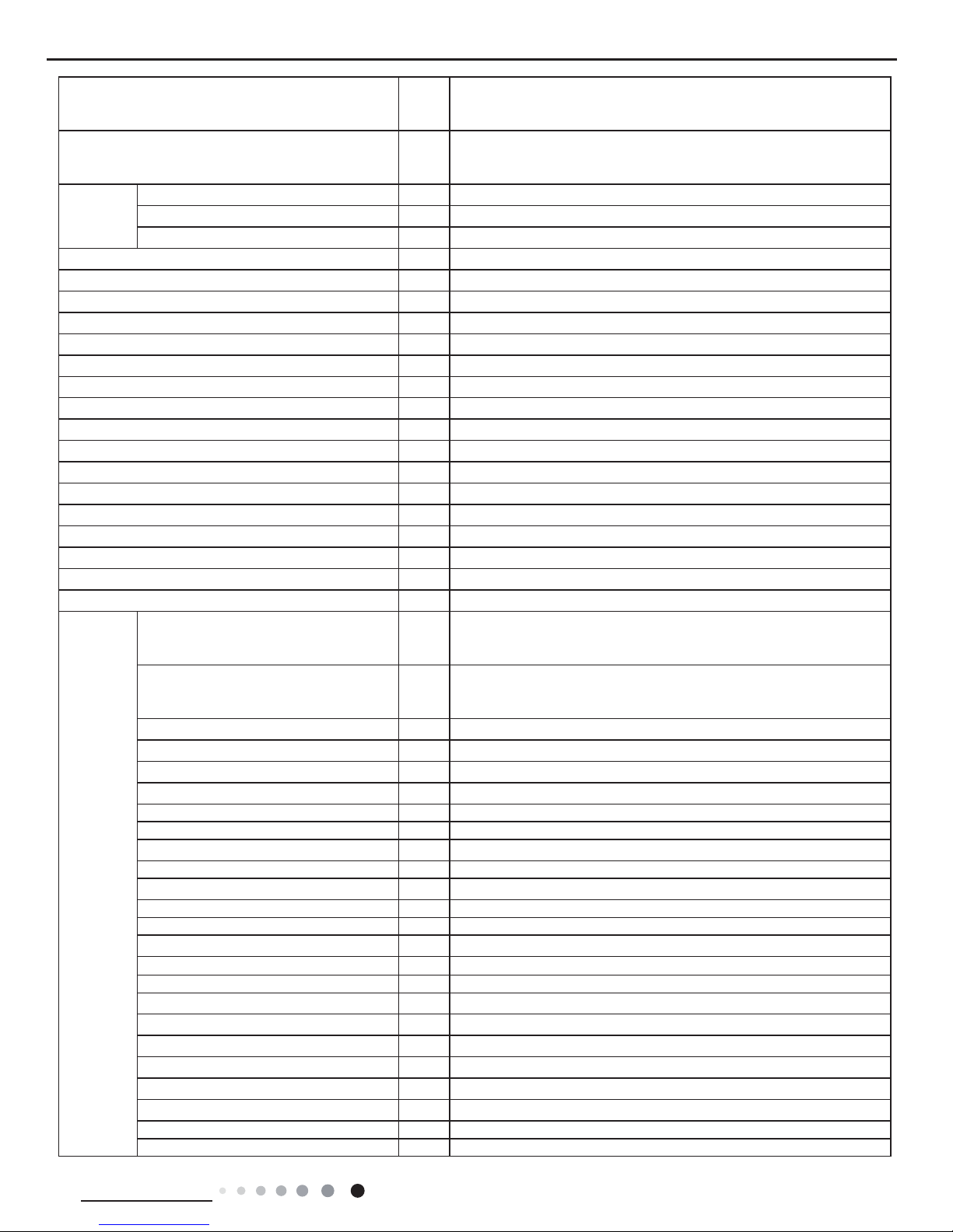
Model
1.GWH18AAD-K6DNA1B 2.GWH18AAD-K6DNA5B
3.GWH18AAD-K6DNA4B
Product Code
1.CB476000600 2.CB488000600/CB488000601
3.CB479001300/CB479001301
Power
Supply
Rated Voltage V~ 220-240
Rated Frequency Hz 50
Phases 1
Power Supply Mode Outdoor
Cooling Capacity W 4600
Heating Capacity W 5200
Cooling Power Input W 1430
Heating Power Input W 1400
Cooling Power Current A 6.3
Heating Power Current A 6.2
Rated Input W 1700
Rated Current A 8
Rated Heating Current A 7.5
Air Flow Volume(SH/H/M/L/SL) m3/h 850/720/610/520/-
Dehumidifying Volume L/h 1.8
EER W/W 3.22
COP W/W 3.71
SEER W/W 6.1
HSPF W/W /
Application Area m
2
21-31
Indoor Unit
Model of Indoor Unit
1.GWH18AAD-K6DNA1B/I 2.GWH18AAD-K6DNA5B/I
3.GWH18AAD-K6DNA4B/I
Product Code of Indoor Unit
1.CB476N00600 2.CB488N00600/CB488N00601
3.CB479N01300/CB479N01301
Fan Type Cross-ow
Diameter Length(DXL) mm Ф106X706
Fan Motor Cooling Speed(SH/H/M/L/SL) r/min 1230/1130/1030/800/-
Fan Motor Heating Speed(SH/H/M/L/SL) r/min 1350/1200/1050/900/Output of Fan Motor W /
Fan Motor RLA A 0.35
Fan Motor Capacitor μF 2.5
Input of Heater W /
Evaporator Form Aluminum Fin-copper Tube
Pipe Diameter mm Ф7
Row-n Gap mm 2-1.4
Coil Length (LXDXW) mm 715X25.4X304.8
Swing Motor Model MP35CP
Output of Swing Motor W 2.5
Fuse A 3.15
Sound Pressure Level (SH/H/M/L/SL) dB (A) 49/45/41/36/-
Sound Power Level (SH/H/M/L/SL) dB (A) 58/55/51/46/-
Dimension (WXHXD) mm 970X300X225
Dimension of Carton Box (LXWXH) mm 1017X366X285
Dimension of Package (LXWXH) mm 1020X369X295
Net Weight kg 13.5
Gross Weight kg 16.5
8
Technical Information
Service Manual
The above data is subject to change without notice; please refer to the nameplate of the unit.
Outdoor Unit
Model of Outdoor Unit GWH18AAD-K6DNA1B/O
Product Code of Outdoor Unit CB476W00600
Compressor Manufacturer/Trademark ZHUHAI LANDA COMPRESSOR CO., LTD
Compressor Model QXF-B096zE190A
Compressor Oil FW68DA
Compressor Type Rotary
L.R.A. A 20
Compressor RLA A 4.21
Compressor Power Input W 943
Overload Protector /
Throttling Method Capillary
Operation Temp
o
C 16~30
Ambient Temp (Cooling)
o
C -15~43
Ambient Temp (Heating)
o
C -15~24
Condenser Form Aluminum Fin-copper Tube
Pipe Diameter mm Φ7
Rows-n Gap mm 2-1.4
Coil Length (LXDXW)
mm
742X38.1X550
Fan Motor Speed rpm 900
Output of Fan Motor W 30
Fan Motor RLA A 0.4
Fan Motor Capacitor μF /
Air Flow Volume of Outdoor Unit m3/h 2200
Fan Type Axial-ow
Fan Diameter mm Φ438
Defrosting Method Automatic Defrosting
Climate Type T1
Isolation I
Moisture Protection IPX4
Permissible Excessive Operating Pressure
for the Discharge Side
MPa 4.3
Permissible Excessive Operating Pressure
for the Suction Side
MPa 2.5
Sound Pressure Level (H/M/L) dB (A) 54/-/-
Sound Power Level (H/M/L) dB (A) 64/-/-
Dimension (WXHXD) mm 848X596X320
Dimension of Carton Box (LXWXH) mm 878X360X630
Dimension of Package (LXWXH) mm 881X363X645
Net Weight kg 34
Gross Weight kg 37
Refrigerant R32
Refrigerant Charge kg 0.77
Connection
Pipe
Length m 5
Gas Additional Charge g/m 16
Outer Diameter Liquid Pipe mm Φ6
Outer Diameter Gas Pipe mm Φ9.52
Max Distance Height m 10
Max Distance Length m 20
Note: The connection pipe applies metric diameter.
9
Technical Information
Service Manual
Parameter Unit Value
Model GWH24AAE-K6DNA4C
Product Code CB479000700
Power
Supply
Rated Voltage V~ 220-240
Rated Frequency Hz 50
Phases 1
Power Supply Mode Outdoor
Cooling Capacity W 6450
Heating Capacity W 6450
Cooling Power Input W 1950
Heating Power Input W 1735
Cooling Current Input A 8.4
Heating Current Input A 8.0
Rated Input W 3100
Rated Current A 13.04
Air Flow Volume(SH/H/M//L/SL) m3/h 1250/1050/950/850/Dehumidifying Volume L/h 2.0
EER W/W 3.3
COP W/W 3.71
SEER W/W 6.30
SCOP(Average/Warmer/Colder) W/W 4.0/5.1/3.3
Application Area m
2
23-34
Indoor
Unit
Indoor Unit Model GWH24AAE-K6DNA4C/I
Indoor Unit Product Code CB479N00700
Fan Type Cross-ow
Fan Diameter Length(DXL) mm Φ108X830
Cooling Speed(SH/H/M//L/SL) r/min 1250/1000/900/800/-
Heating Speed(SH/H/M//L/SL) r/min 1250/1000/900/850/-
Fan Motor Power Output W 35
Fan Motor RLA A 0.35
Fan Motor Capacitor μF 3
Evaporator Form Aluminum Fin-copper Tube
Evaporator Pipe Diameter mm Ф7
Evaporator Row-n Gap mm 2-1.4
Evaporator Coil Length (LXDXW) mm 845X25.4X342.9
Swing Motor Model MP35CJ
Swing Motor Power Output W 2.5
Fuse Current A 3.15
Sound Pressure Level(SH/H/M//L/SL) dB (A) 49/44/41/39/-
Sound Power Level(SH/H/M//L/SL) dB (A) 63/59/56/53/-
Dimension (WXHXD) mm 1078X325X246
Dimension of Carton Box (LXWXH) mm 1145X410X335
Dimension of Package(LXWXH) mm 1148X413X350
Net Weight kg 16.5
Gross Weight kg 20
10
Technical Information
Service Manual
Outdoor
Unit
Outdoor Unit Model GWH24QE-K6DNA1C/O
Outdoor Unit Product Code CB419W12200
Compressor Manufacturer ZHUHAI LANDA COMPRESSOR CO,LTD.
Compressor Model QXFS-D23zX090A
Compressor Oil FW68DA
Compressor Type Rotary
Compressor LRA. A 25
Compressor RLA A 11.50
Compressor Power Input W 2400
Compressor Overload Protector 1NT11L-6233 or HPC115/95/ or KSD115ºC
Throttling Method Electron expansion valve
Set Temperature Range ºC 16~30
Cooling Operation Ambient Temperature
Range
ºC -15~43
Heating Operation Ambient Temperature
Range
ºC -15~24
Condenser Form Aluminum Fin-copper Tube
Condenser Pipe Diameter mm Φ7
Condenser Rows-n Gap mm 2-1.4
Condenser Coil Length (LXDXW) mm 935X38.1X660
Fan Motor Speed rpm 800
Fan Motor Power Output W 60
Fan Motor RLA A 0.58
Fan Motor Capacitor μF /
Outdoor Unit Air Flow Volume m3/h 3200
Fan Type Axial-ow
Fan Diameter mm Ф520
Defrosting Method Automatic Defrosting
Climate Type T1
Isolation I
Moisture Protection IPX4
Permissible Excessive Operating Pressure
for the Discharge Side
MPa 4.3
Permissible Excessive Operating Pressure
for the Suction Side
MPa 2.5
Sound Pressure Level (H/M/L) dB (A) 58/-/-
Sound Power Level (H/M/L) dB (A) 68/-/-
Dimension(WXHXD) mm 963X700X396
Dimension of Carton Box (LXWXH) mm 1026X455X735
Dimension of Package(LXWXH) mm 1029X458X750
Net Weight kg 52.5
Gross Weight kg 57
Refrigerant R32
Refrigerant Charge kg 1.7
Connection
Pipe
Connection Pipe Length m 5
Connection Pipe Gas Additional Charge g/m 50
Outer Diameter Liquid Pipe mm Ф6
Outer Diameter Gas Pipe mm Ф16
Max Distance Height m 10
Max Distance Length m 25
Note: The connection pipe applies metric diameter.
The above data is subject to change without notice. Please refer to the nameplate of the unit.
11
Technical Information
Service Manual
2.2 Capacity Curve in Different Outdoor Temperature
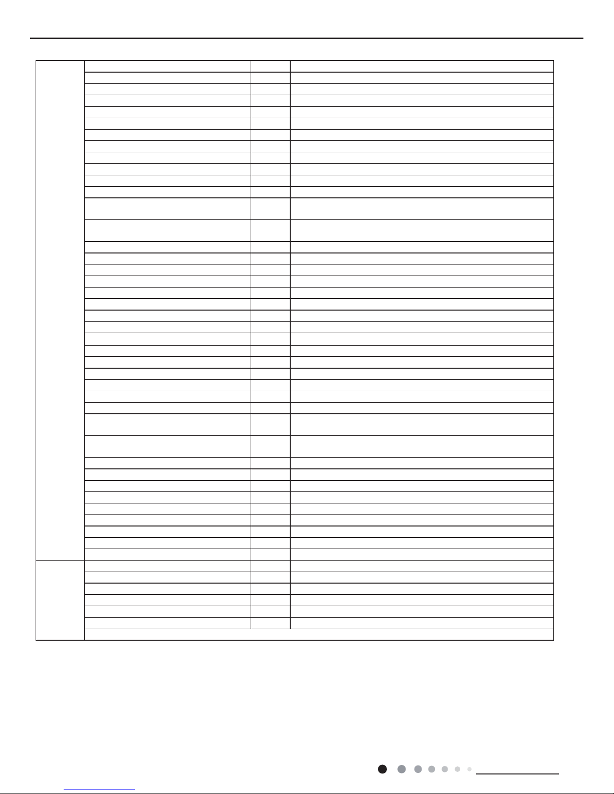
2.3 Cooling and Heating Data Sheet in Rated Frequency
Heating
Rated heatling condition(°C)
(DB/WB)
Model
Pressure of gas pipe connecting
indoor and outdoor unit
Inlet and outlet pipe temperature
of heat exchanger
Fan speed of
indoor unit
Fan speed of
outdoor unit
Indoor Outdoor P (MPa) T1 (°C) T2 (°C)
20/- 7/6 18/24K 3.5~3.8
in:75~85
out:37~43
in:1~3
out:2~5
Super High High
Rated cooling condition(°C)
(DB/WB)
Model
Pressure of gas pipe connecting
indoor and outdoor unit
Inlet and outlet pipe temperature
of heat exchanger
Fan speed of
indoor unit
Fan speed of
outdoor unit
Indoor Outdoor P (MPa) T1 (°C) T2 (°C)
27/19 35/24 18/24K 0.8~1.0
in:8~11
out:11~14
in:75~85
out:37~43
Super High High
Cooling
Instruction:
T1: Inlet and outlet pipe temperature of evaporator
T2: Inlet and outlet pipe temperature of condenser
P: Pressure at the side of big valve
Connection pipe length: 5m.
Cooling Heating
32 33 34 35 36 37 38 39 43 –15 –10 –5
40 41 42
100
105
95
90
85
80
75
70
65
60
55
50
110
100
90
80
70
60
50
40
05
710
Conditions
Indoor:DB27°C/WB19°C
Indoor air flow:Super High
Pipe length: 5m
Conditions
Indoor:DB20°C/WB15°C
Indoor air flow:Super High
Pipe length: 5m
Outdoor temp.(°C) Outdoor temp.(°C)
Capacity ratio (%)
Capacity ratio (%)
Cooling Heating
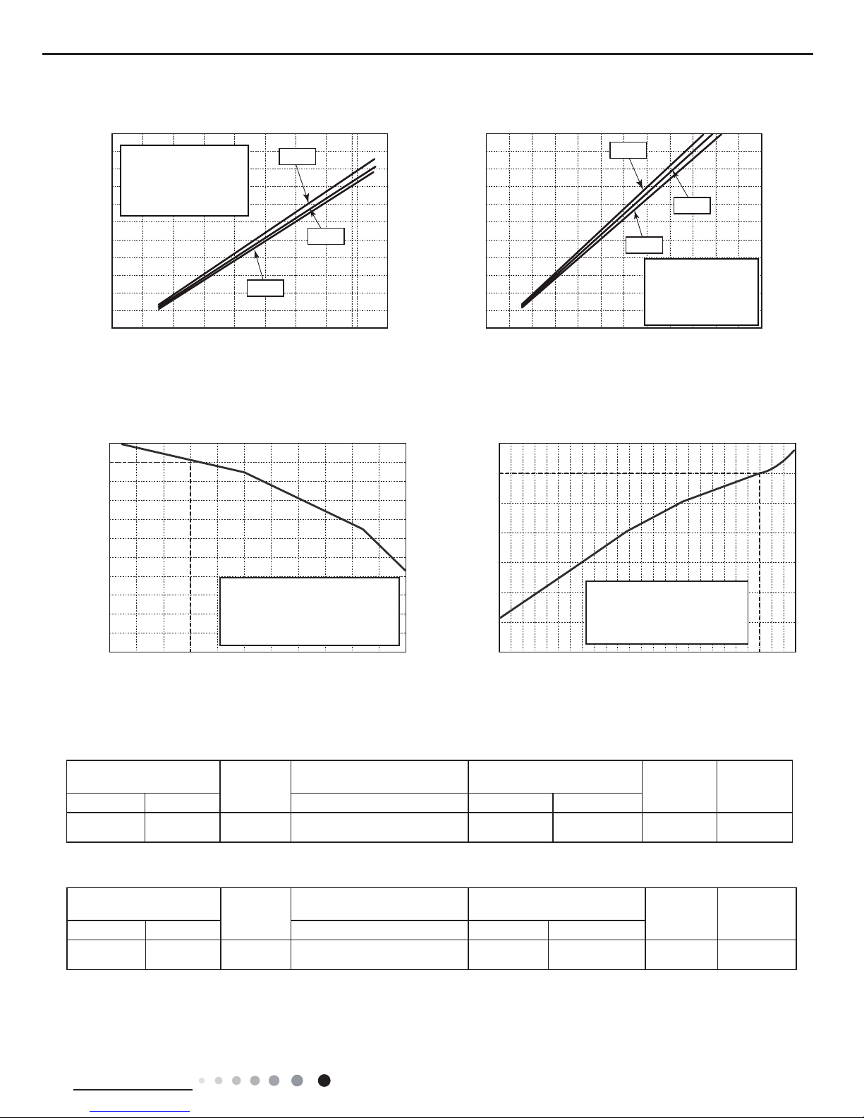
2.2 Operation Characteristic Curve
01020304050607090010 20 30 40 50 60 70 80 90 100 120 110
80
11
10
9
8
7
6
5
4
3
2
1
0
Compressor speed (rps)
) A ( t n e r r u C
11
10
9
8
7
6
5
4
3
2
1
0
Compressor speed (rps)
) A ( t n e r r u C
220V
230V
240V
220V
230V
240V
01020304050607090010 20 30 40 50 60 70 80 90 100
120
110
80
11
10
9
8
7
6
5
4
3
2
1
0
Compressor speed (rps)
)A(tnerruC
11
10
9
8
7
6
5
4
3
2
1
0
Compressor speed (rps)
)A(tnerruC
220V
230V
240V
220V
230V
240V
Conditions
Indoor: DB27°C/WB19°C
Outdoor: DB35°C/WB24°C
Indoor air flow: High
Pipe length: 5m
Conditions
Indoor: DB27°C/WB19°C
Outdoor: DB35°C/WB24°C
Indoor air flow: High
Pipe length: 5m
Conditions
Indoor: DB20°C/WB15°C
Outdoor: DB7°C/WB6°C
Indoor air flow: High
Pipe length: 5m
Conditions
Indoor: DB20°C/WB15°C
Outdoor: DB7°C/WB6°C
Indoor air flow: High
Pipe length: 5m
Cooling Heating
12
Technical Information
Service Manual
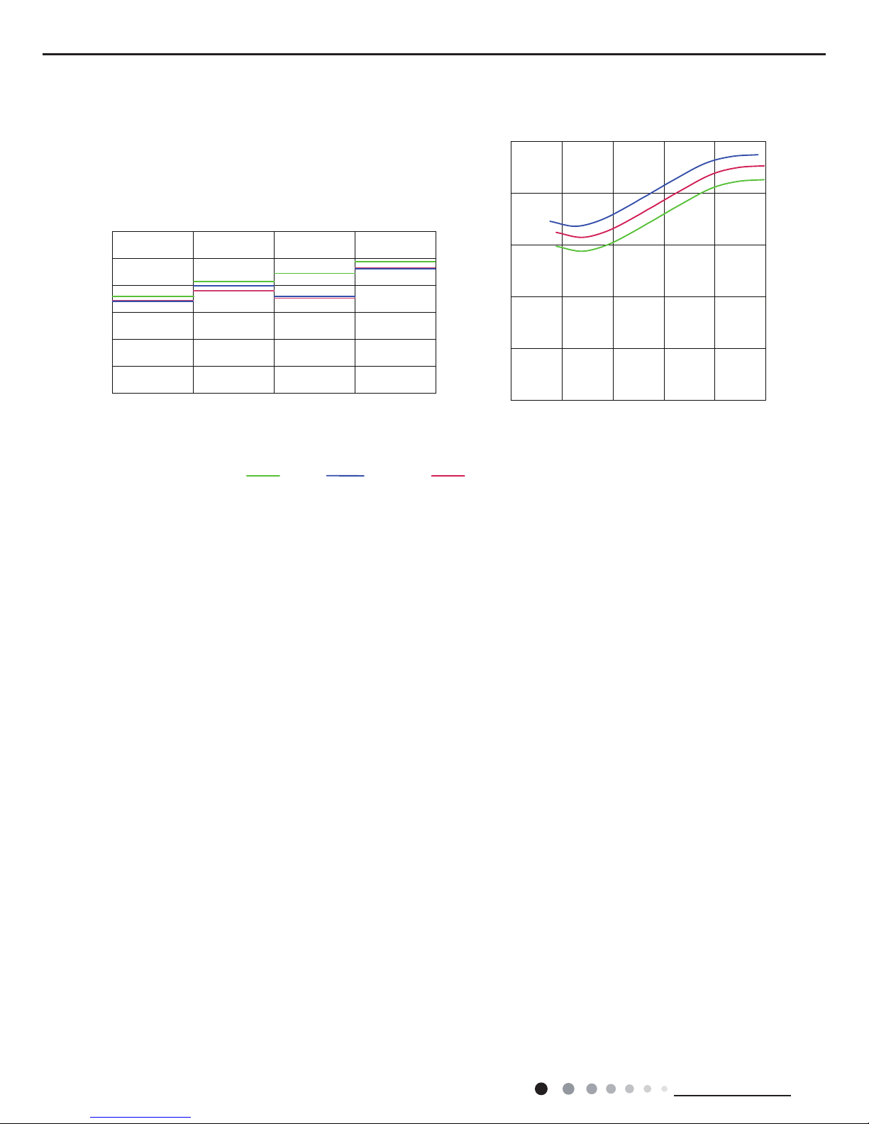
2.5 Noise Curve
Indoor side noise
60
50
40
30
20
10
0
Indoor Fan Motor Rotating Speed
Noice/dB(A)
low
Middle
High Super High
Outdoor side noise
Compressor frequency/Hz
Noise/dB(A)
70
60
50
40
30
02040608
01
00
20
24KGWH18AAD-K6DNA1B GWH18AAD-K6DNA1A
13
Technical Information
Service Manual
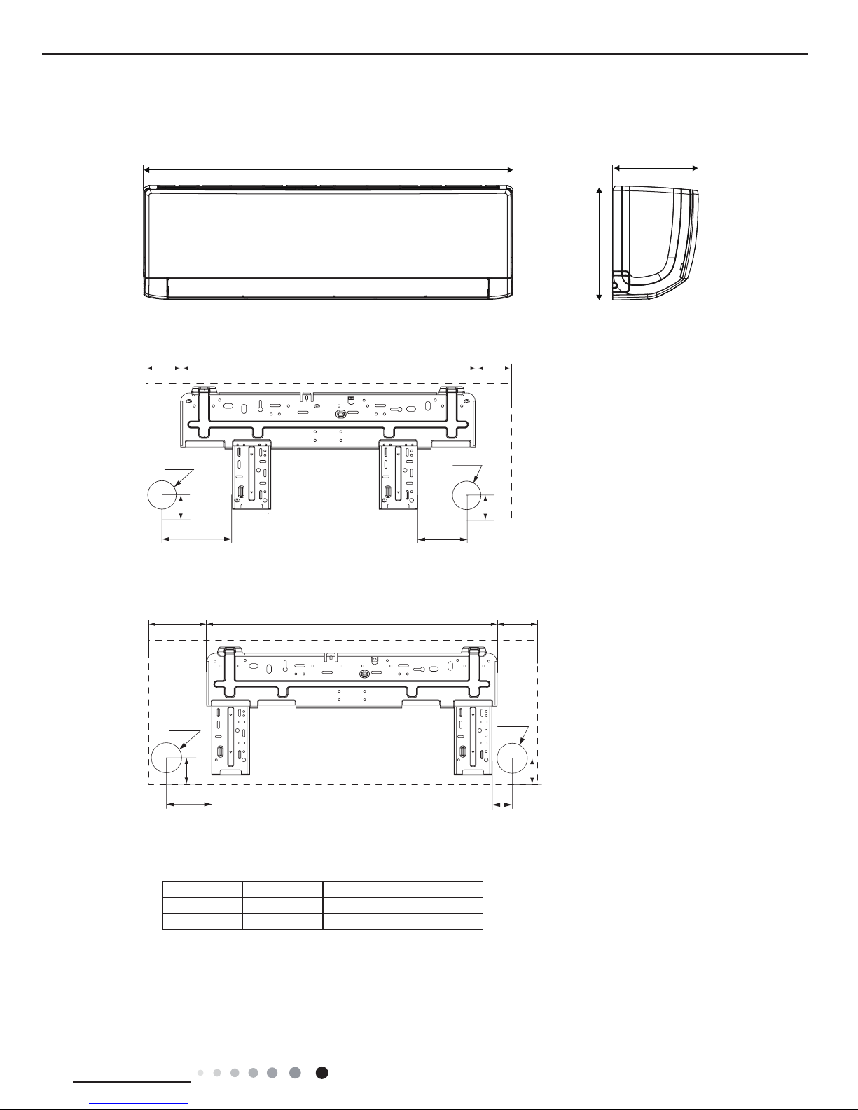
104 685 181
140
190
38
Φ55
Φ55
38
79
154
43
206 685 187
Φ70
Φ70
43
24AAE
18/24AAD
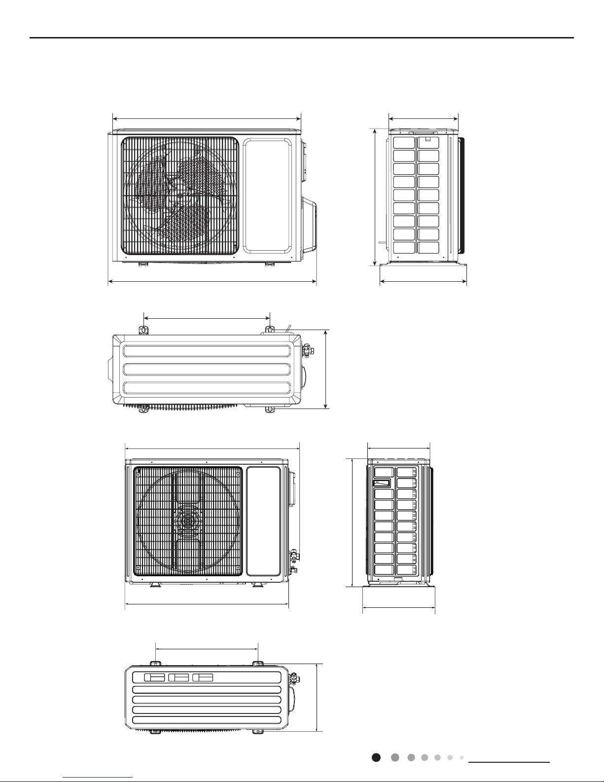
3. Outline Dimension Diagram
3.1 Indoor Unit
Unit:mm
Model W H D
18/24AAD 970 300 225
24AAE 1078 325 246
14
Technical Information
Service Manual
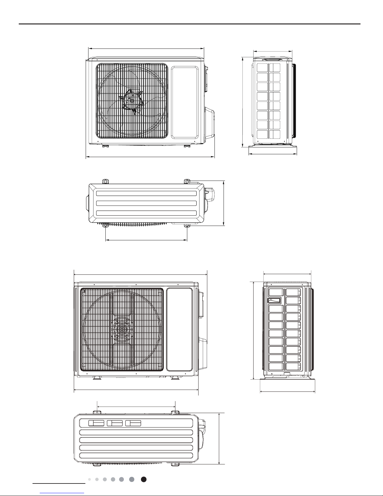
3.2 Outdoor Unit
899
818
596
378
303
343
550
Unit:mm
Unit:mm
897
560
955 340
396
364
700
GWH18AAD-K6DNA1A/O
24K
15
Technical Information
Service Manual
GWH18AAD-K6DNA1B/O
GWH24QE-K6DNA1C/O
780
596
848
286
540
320
257
340
963
700
396
890
560
364
Unit:mm
Unit:mm
16
Technical Information
Service Manual
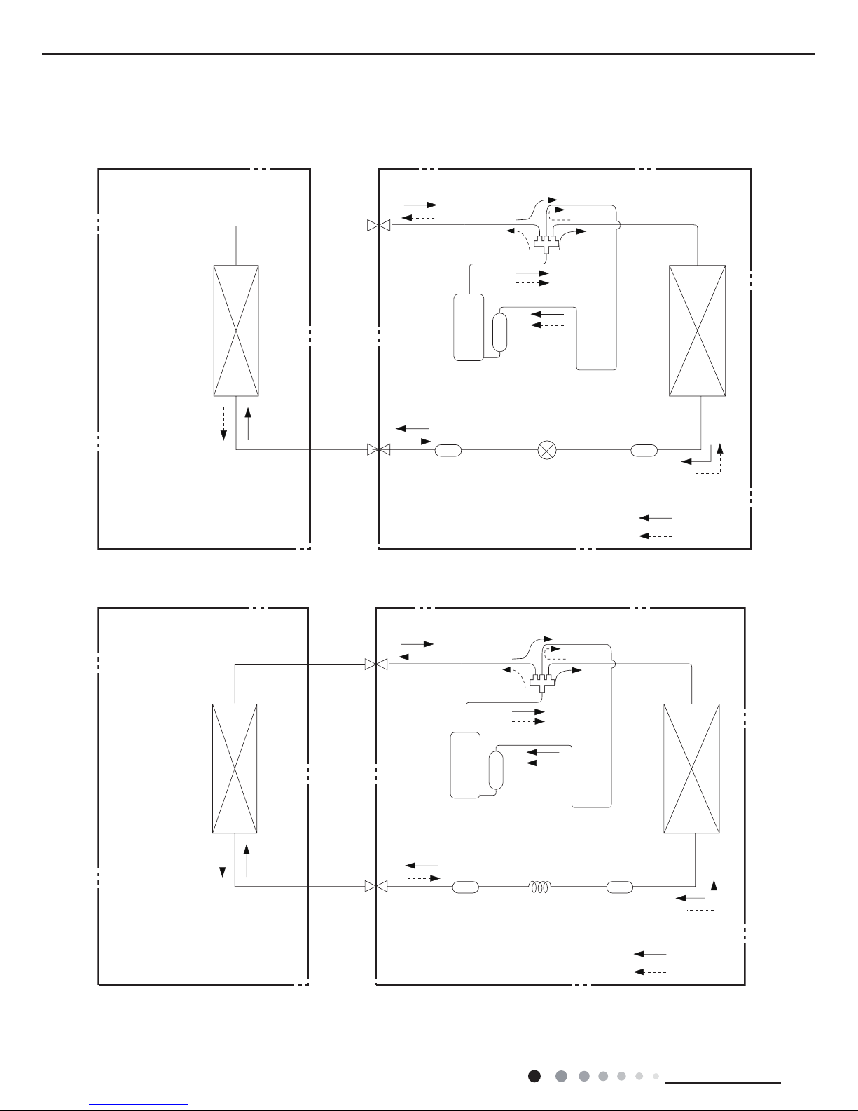
4. Refrigerant System Diagram
Connection pipe specication:
Liquid pipe:1/4" (6mm)
Gas pipe:3/8" (9.52mm) GWH18AAD-K6DNA1B GWH18AAD-K6DNA5B GWH18AAD-K6DNA4B
Gas pipe:1/2" (12mm) 18K except GWH18AAD-K6DNA1B GWH18AAD-K6DNA5B GWH18AAD-K6DNA4B
Gas pipe:5/8" (16mm) 24K
Indoor unit
Outdoor unit
COOLING
HEATING
4-Way valve
Discharge
Suction
Heat
exchanger
(evaporator)
Heat
exchanger
(condenser)
Valve
Valve
Liquid pipe
side
Gas pipe
side
Strainer Electric
expand
valve
Strainer
Compressor
Accumlator
Indoor unit
Outdoor unit
COOLING
HEATING
4-Way valve
Discharge
Suction
Heat
exchanger
(evaporator)
Heat
exchanger
(condenser)
Valve
Valve
Liquid pipe
side
Gas pipe
side
Strainer CapillaryStrainer
Accumlator
Compressor
GWH18AAD-K6DNA1A GWH18AAD-K6DNA5A GWH18AAD-K6DNA4A GWH18AAD-K6DNA2A
GWH24AAD-K6DNA1A GWH24AAD-K6DNA5A GWH24AAD-K6DNA4A GWH24AAD-K6DNA5A
GWH24AAD-K6DNA2A GWH24AAE-K6DNA4C
GWH18AAD-K6DNA1B GWH18AAD-K6DNA5B GWH18AAD-K6DNA4B GWH18AAD-K6DNA5B
17
Technical Information
Service Manual
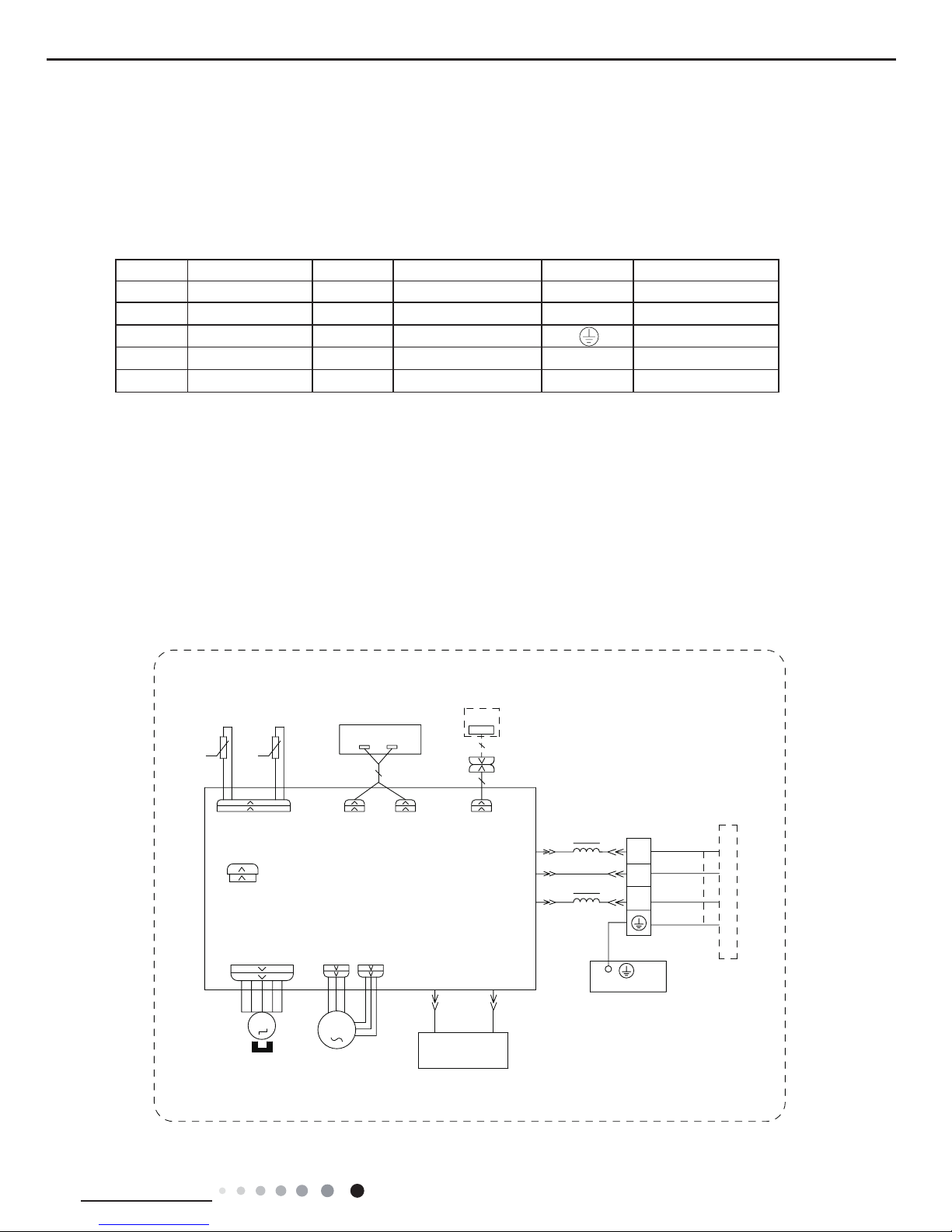
Symbol Symbol Color Symbol Symbol Color Symbol Name
WH White GN Green CAP Jumper cap
YE Yellow BN Brown COMP Compressor
RD Red BU Blue Grounding wire
YEGN Yellow/Green BK Black / /
VT Violet OG Orange / /
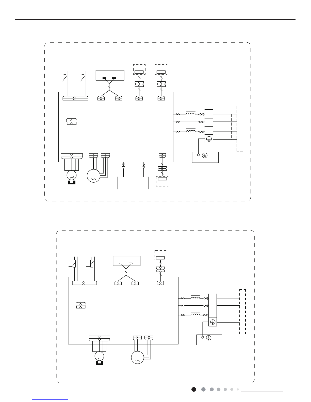
5. Electrical Part
5.1 Wiring Diagram
● Indoor Unit
●Instruction
Note: Jumper cap is used to determine fan speed and the swing angle of horizontal lover for this model.
60000700068802
76(1625
7(03
6(1625
7(03
6(1625
57
522078%(
67(33,1*
',63/$<
35,17('&,5&8,7%2$5'
5(&(,9(5$1'
',63/$<%2$5'
&$%/(
&211(&7,1*
6:,1*8'
02725
%/2&.
7(50,1$/
$3
-803
&$3
%8
%.
<(*1
(9$325$725
3(
;7
1
0
287'22581,7
$3
3*
*(1(5$725
&2/'3/$60$
)$102725
0
5' %8
+($/7+1
+($/7+/
3*)
',63 ',63
%1
<(*1
57
1
&20287
$&/
%8
%.
%1
/
/
:,),
02'8/(
:,),
$3
0$*1(7,&
5,1*
All models is except:GWH24AAE-K6DNA4C/I GWH18AAD-K6DNA1A/I(CB476N00201)
GWH24AAD-K6DNA1A/I(CB476N00101) GWH18AAD-K6DNA5B/I GWH24AAD-K6DNA5A/I
GWH24AAD-K6DNA4A/I GWH18AAD-K6DNA2A/I GWH24AAD-K6DNA2A/I
GWH18AAD-K6DNA4B/I(CB479N01301)
18
Technical Information
Service Manual
76(1625
7(03
6(1625
7(03
6(1625
57
522078%(
67(33,1*
',63/$<
35,17('&,5&8,7%2$5'
5(&(,9(5$1'
',63/$<%2$5'
&$%/(
&211(&7,1*
6:,1*8'
02725
%/2&.
7(50,1$/
$3
-803
&$3
%8
%.
<(*1
(9$325$725
3(
;7
1
0
287'22581,7
$3
3*
)$102725
0
3*)
',63 ',63
%1
<(*1
57
1
&20287
%8
%.
%1
/
/
:,),
02'8/(
:,),
$3
$&//
0$*1(7,&
5,1*
60000700068803
60000700068811
:,5('
&21752//(5
&200$18$/
76(1625
7(03
6(1625
7(03
6(1625
57
522078%(
67(33,1*
',63/$<
35,17('&,5&8,7%2$5'
5(&(,9(5$1'
',63/$<%2$5'
&$%/(
&211(&7,1*
6:,1*8'
02725
%/2&.
7(50,1$/
$3
-803
&$3
%8
%.
<(*1
(9$325$725
3(
;7
1
0
287'22581,7
$3
3*
*(1(5$725
&2/'3/$60$
)$102725
0
5' %8
+($/7+1
+($/7+/
3*)
',63 ',63
%1
<(*1
57
1
&20287
$&/
%8
%.
%1
/
/
:,),
02'8/(
:,),
$3
$3
$3
'5<&
'225&
237,21$/
'5<&217$&7
0$*1(7,&
5,1*
GWH24AAE-K6DNA4C/I
GWH18AAD-K6DNA1A/I(CB476N00201) GWH24AAD-K6DNA1A/I(CB476N00101 )
GWH18AAD-K6DNA5B/I GWH24AAD-K6DNA5A/I GWH24AAD-K6DNA4A/I GWH18AAD-K6DNA2A/I
GWH24AAD-K6DNA2A/I GWH18AAD-K6DNA4B/I(CB479N01301)
19
Technical Information
Service Manual
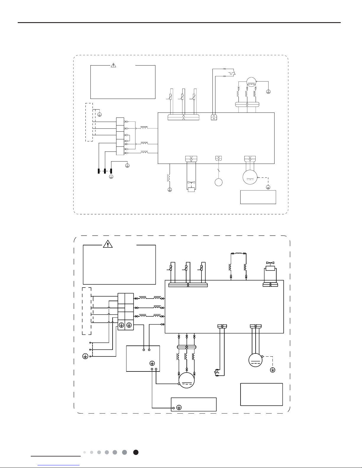
● Outdoor Unit
63610000218
$&B/
1
&20B,11(5
:$51,1*
3OHDVHGRQWWRXFKDQ\
WHUPLQDOZKHQWKHYROWDJH
RIWHUPLQDO3'&DQG
1'&DW$3LVKLJKHU
WKDQ9WRSUHYHQWWKH
ULVNRIHOHFWULFVKRFN
$3
7(036(1625
(;+$867
7(036(1625
2875220
28778%(
7(036(1625
%.:+
%8 <(
;
&203
6$7
:+ :+
29&B&203
5'
575757
3(
3(
5'%8 <(
8%8 9<( :5'
<(*1
29(5/2$'3527(&725
/
0$*1(7,&
5,1*
//
3(
<(*1
3(
9DOYH
([SDQVLRQ
(OHFWURQLF
(.9
3(
0
:$<
<9
9$/9(
97 97
)$ 2)$1:$<
)$102725
<(*1
3(
35,17('&,5&8,7%2$5'
8
9
:
/
&203
7B6(1625
%1%.
32:(5
/
/
0$*1(7,&
3(
7(50,1$/
%/2&.
<(*1
%8
%1
%8
%1
%.
5,1*
/
,1'22581,7
;7
%8
%.
%1
1
/
1
3(
%8
<(*1
/1
...
LURQVKHOOPRWRU
RQO\DSSOLHVWRWKH
1RWH0RWRUJURXQG
These wiring diagrams are subject to change without notice; please refer to the one supplied with the unit.
GWH18AAD-K6DNA1A/O GWH24AAD-K6DNA1A/O GWH24QE-K6DNA1C/O
GWH18AAD-K6DNA1B/O
600007000884
,1'22581,7
127(0RWRU
DSSOLHVWRWKH
LURQVKHOOPRWRU
JURXQGRQO\
RIHOHFWULFVKRFN
3OHDVHGRQWWRXFKDQ\
WHUPLQDOZKHQWKHPDFKLQHLV
UXQQLQJVWRSSLQJRUKDVEHHQ
SRZHUHGRIIIRUOHVVWKDQ
PLQXWHVWRSUHYHQWWKHULVN
:$51,1*
<(*1
%8
%.
%1
1
/
1
/
/
/
/
/
%8
%.
%1
0$*1(7,&5,1*
7(50,1$/
;7
%/2&.
1
$&/
&208
3(
&1
7(03
6(1625
7(03
6(1625
7(03
57
57
57
6(1625
N
N
N
28778%(
2875220
(;+$867
<9
:$<
:$<
9$/9(
97
97
/;
/;
/
/
5($&725
/
%8
%1
0$*1(7,&
5,1*
$30DLQ%RDUG
2)$1
)$1
0
3(
3(
<(*1
02725
3527(&725
29(5/2$'
5'
29&&203
6$7
5'
/
:
9
8
&203
&203
:
9
8
;
%8
<(
5'
0$*1(7,&
5,1*
32:(5
/
1
<(*1
%8
%1%.
<(*1
<(*1
3(
<(*1
(/(&75,&$/
%2;
3(
<(*1
%8
<(
5'
0,',62/$7,21
6+((7
3(
20
Technical Information
Service Manual
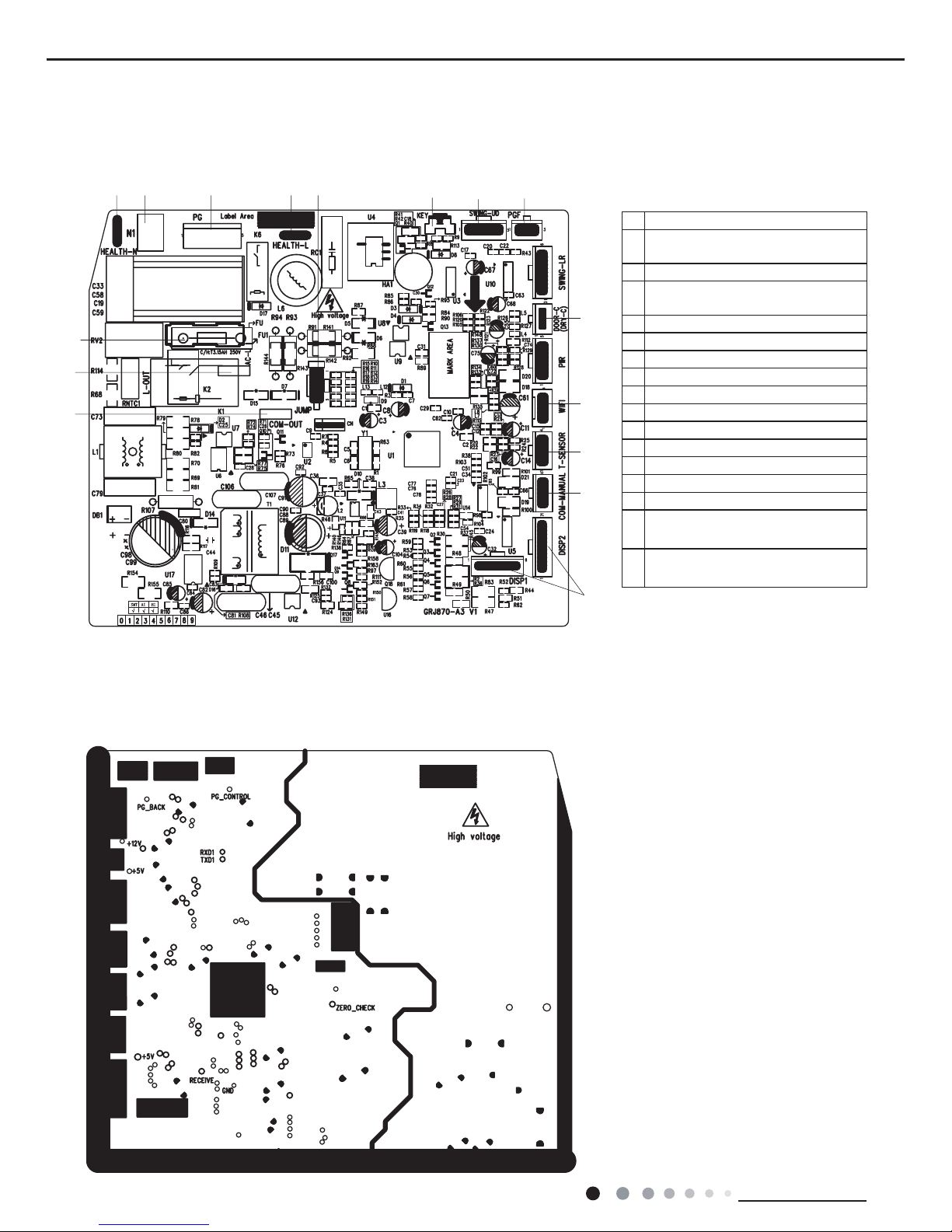
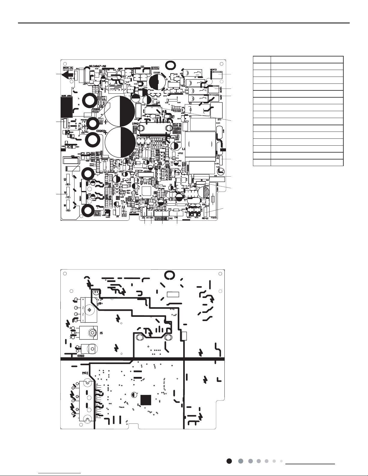
5.2 PCB Printed Diagram
No Name
1
Interface of communication wire for
indoor unit and outdoor unit
2 Interface of live wire
3
Interface of health function neutral
wire
4 Interface of neutral wire
5 Interface of fan
6 Interface of health function live wire
7 Jumper cap
8 Auto button
9 Up&down swing interface
10 Feedback interface of indoor unit
11 Fuse
12 Interface of wi
13 Needle stand for temperature sensor
14 Display interface
15
Interface of dry contact(only for the
model with this function)
16
Wired controller (only for the mode
with this function)
Indoor Unit
● Top view
● Bottom view
1
2
11
3 4 5
6
7
8
9 10
12
13
14
16
15
21
Technical Information
Service Manual
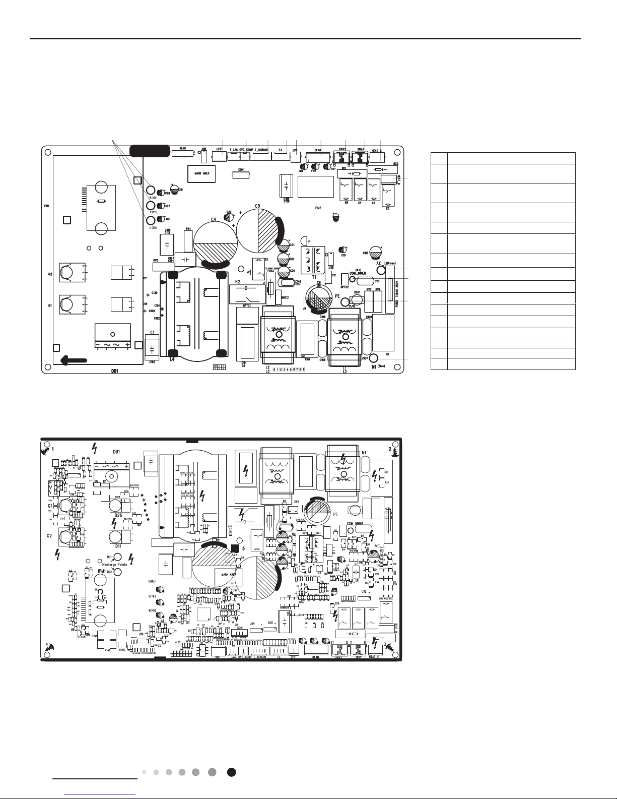
Outdoor Unit
● Top view
● Bottom view
No.Name
1
2
3
4
Interface of temperature sensor
5
6
7
8
9
10
11
12
123456 78910
11
12
13
14
15
Compressor three phase input
interface
Terminal of system high pressure
protection
Compressor overload protection
terminal
Terminal of electronic expansion
valve
Terminal for low pressure protection
Interface of fan
4-way valve terminal
2-way valve terminal
Terminal of compressor electric heater
Terminal of chassis electric heater
Live wire
13 Communication wire
14 Grounding wire
15 Neutral wire
GWH18AAD-K6DNA1A/O
24K
22
Technical Information
Service Manual
4
5
6
7
8
9
10
11
1
2
3
12131415
● Top view
● Bottom view
No. Name
1 Compressor
2 Reactor 2
3 Reactor 1
4 Chassis electric heating
5 Compressor electric heating
6 4-way valve
7 DC fan
8 Earthing wire
9
Communication wire
10 Neutral wire
11 Live wire
12 Electronic expansion valve
13 Temperature sensor
14 Overloard
15 DRED
GWH18AAD-K6DNA1B/O
23
Technical Information
Service Manual
6. Function and Control
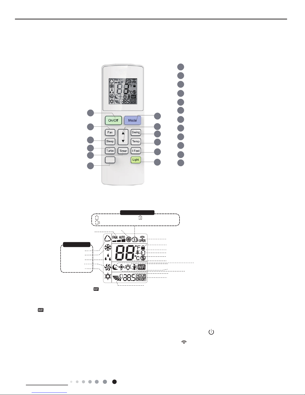
6.1 Remote Controller Introduction
Icon Display on Remote Controller
Operation introduction of remote controller
Note:
“ ” This is a general remote controller. Some models have this function while some do not. Please refer to the
actual models.
● This is a general use remote controller, it could be used for the air conditioners with multifunction; For some function, wh
ich
the model doesn't have, if press the corresponding button on the remote controller that the unit will keep the original running
status.
●After putting through the power, the air conditioner will give out a sound.Operation indicator " " is ON (red indicator, th
e colour is
different for different models). After that, you can operate the air conditioner by using remote controller
.
● Under on status, pressing the button on the remote controller, the signal icon " "on the display of remote controller wi
ll
blink once and the air conditioner will give out a “de” sound, which means the signal has been sent to the air conditioner
.
● Under off status, set temperature and clock icon will be displayed on the display of remote controller (If timer on, timer of
f and
light functions are set, the corresponding icons will be displayed on the display of remote controller at the same time); Under
on
status, the display will show the corresponding set function icons.
Buttons on remote controller
1
2
5
4
6
7
8
11
12
9
On/Off button
▲/ button
3
Fan button
Swing button
WiFi button
Turbo button
Light button
10
Temp button
I Feel button
Timer button
Sleep button
Mode button
▲
2
5
7
9
4
12
3
1
6
8
10
11
Send signal
Turbo mode
8ć heating function
Set temperature
Set time
TIMER ON /TIMER OFF
Child lock
Up & down swing
Set fan speed
Light function
Temp. display type
:Set temp.
:Outdoor ambient temp.
:Indoor ambient temp.
Sleep mode
Heat mode
Fan mode
Dry mode
Cool mode
Auto mode
Operation mode
I feel function
X-fan mode
health function
ventilation operation
NOTICE:
“ ” This is a general remote controller. Some models have this function while some
do not. Please refer to the actual models.
WiFi
24
Technical Information
Service Manual
1. ON/OFF button
2. MODE button
3. F
AN button
6. SLEEP button
5. SWING button
Press this button to turn on the unit. Press this button again to turn off the unit.
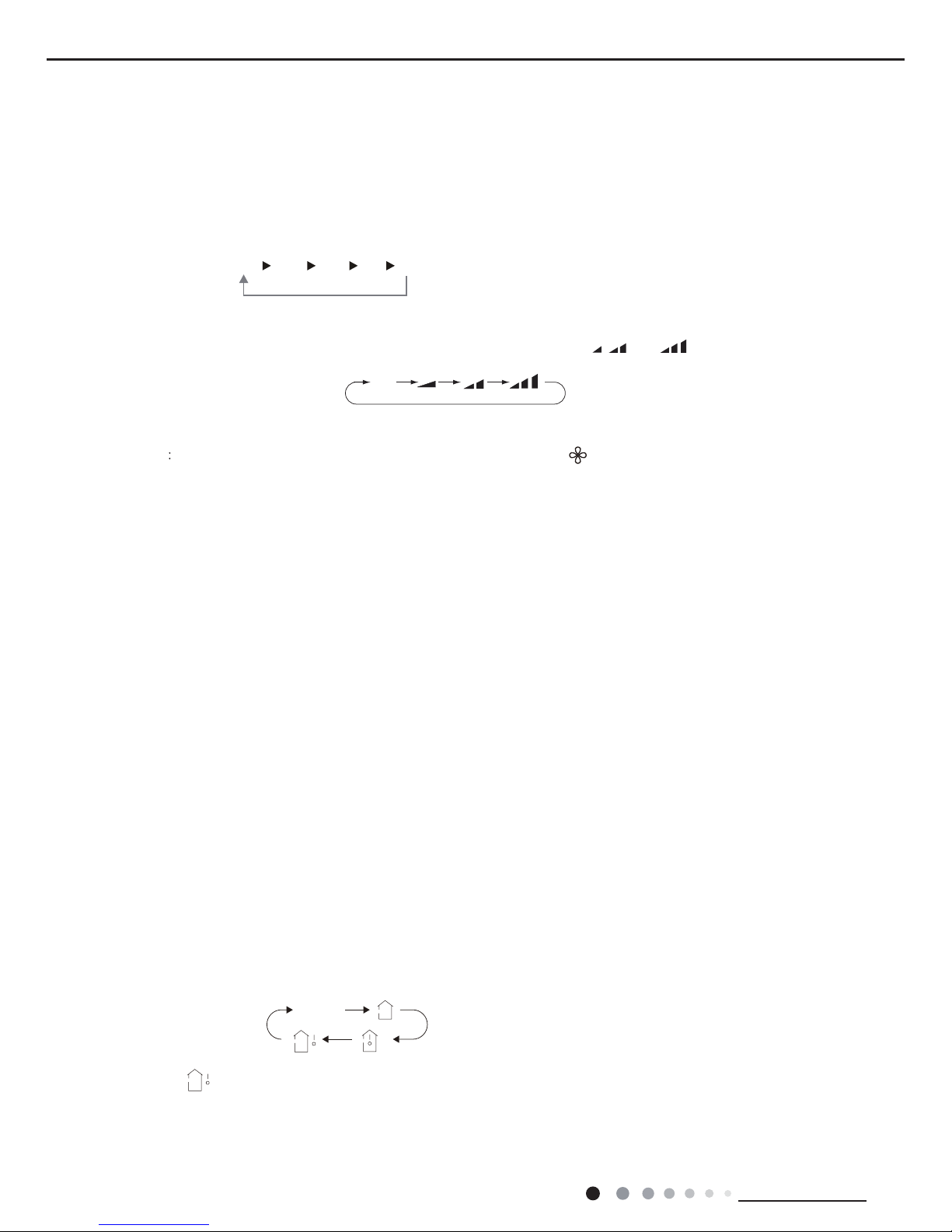
Each time you press this button,a mode is selected in a sequence that goes from AUTO, COOL, DRY, FAN, and HEAT *,
as the following:
AUTO COOL DRY FAN
HEAT
*
* Note: Only for models with heating function.
This button is used for setting Fan Speed in the sequence that goes from AUTO,
, to , then back to Auto.
4.▲ / button
▲
Press this button to set up & down swing angle.
Auto
* Note: Fan speed under dry mode is low speed.
This function indicates that moisture on evaporator of indoor unit will be blowed after the unit is stopped to avoid mould.
Having set X-FAN function on: After turning off the unit by pressing ON/OFF button indoor fan will continue running for a few
minutes. at low speed. In this period, Hold fan speed button for 2s to stop indoor fan directly.
Having set X-FAN function off: After turning off the unit by pressing ON/OFF button, the complete unit will be off directly.
X-FAN function
Hold fan speed button for 2s in COOL or DRY mode, the icon “ ” is displayed and the indoor fan will continue
operation for a few minutes in order to dry the indoor unit even though you have turned off the unit. After energization, X-FAN
OFF is defaulted. X-FAN is not available in AUTO, FAN or HEAT mode.
●
●
●
Under Cool, Heat mode, press this button to turn on Sleep function. Press this button again to cancel Sleep function.
Under Fan、DRY and Auto modes, this function is unavailable.
▲Press / button to increase/decreaseset temperature. In AUTO mode, set temperature is not adjustable.
▲
▲
When setting Timer On or Timer Off, press "▲" or " " button to adjust the time.
7. TEMP button
Note:
●
Outdoor temperature display is not available for some models. At that time, indoor
unit receives " " signal, while it displays indoor set temperature.
Press this button, you can see indoor set temperature, indoor ambient temperature
on indoor unit’s display.
The setting on remote controller is selected circularly as below:
no display

25
Technical Information
Service Manual
8. TURBO button
9. I FEEL button
10. Timer button
11. WiFi button
12. LIGHT button
Function introduction for combination buttons
Press " " and " "
buttons simultaneously 3s to lock or unlock the keypad. If the remote
pressing any button, blinks three times.
controller is locked, is displayed. In this case,
▲
Combination of "" and " " buttons: About lock
▲
▲
▲
About switch between Fahrenheit and centigradeCombination of "MODE" and " " buttons:
▲
At unit OFF, press "MODE" and " " buttons simultaneously to
switch between ć and .
▲
Nixie tube on the remote controller displays
"SE"
. Repeat the operation to quit the function.
Combination of "TEMP" and "TIMER" buttons: About Energy-saving Function
Press "TEMP" and "TIMER" simultaneously in COOL mode to start energy-saving function.
(46 if Fahrenheit is adopted). Repeat the operation to quit the function.
Combination of "TEMP" and "TIMER" buttons:
About 8
ć
Heating Function
Press "TEMP" and "
TIMER
" simultaneously in HEAT mode to start 8ć Heating Function
Nixie tube on the remote controller displays "
"
and a selected temperature of
"8ć".
Press this button to start I FEEL function and " " will be displayed on the remote controller. After this function is set,
the remote controller will send the detected ambient temperature to the controller and the unit will automatically adjust the
indoor temperature according to the detected temperature. Press this button again to close I FEEL function
and " " will disappear. When I FEEL function is turned on,the remote controller should be put within the area
where indoor unit can receive the signal sent by the remote controller.
will change quickly if holding " " or " " button).
Press this button again to confirm timer setting and the characters of HOUR ON (OFF)will stop flashing.
If the characters are flashing but you haven’t press timer button,timer setting status will be quit after 5s.
If timer is confirmer, press this button again to cancel timer.
● Under ON status, press this button to set timer OFF; Under OFF status, press
this button to set timer ON.
● Press this button once and the characters of HOUR ON (OFF) will flash to be displayed. Meanwhile,
press " " button or " " button to adjust timer setting (time
Under COOL or HEAT mode, press this button to activate / deactivate the Turbo function.
▲
▲
▲
▲
Time setting range is 0.5~24hours.
Press this button to
turn on the display's light and press this button again to turn off the display's
light.
● This function is only available for some models.
Press " WiFi " button to turn on or turn off WiFi function. When WiFi function is turned on, the " WiFi " icon will be
WiFi module displayed on remote controller; Under status
displayed on remote controller; Under status of unit off, press "MODE" and " WiFi " buttons simultaneously for 1s,
will restore to factory default setting.
26
Technical Information
Service Manual
WIFI Function
Press this button to turn on the unit. Press this button again to turn off the unit. Press "MODE" and "TURBO" button simultaneously to
and "TURBO" buttons simultaneously for
10s, remote controller will send WIFI reset code and then the WIFI function will be turned on.
WIFI function is defaulted ON after energization of the remote controller.
turn on or turn off WIFI function. When WIFI function is turned on, the " " icon will be displayed on remote controller
; Long press "MODE"
● This function is only available for some models.
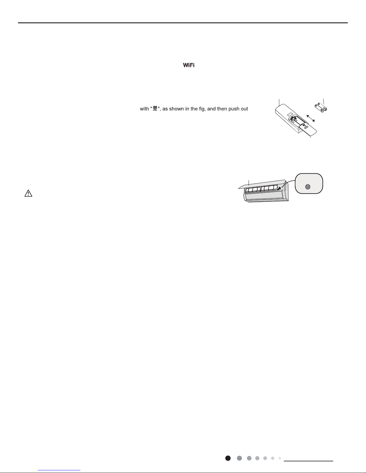
Replacement of batteries in remote controller
Emergency operation
If remote controller is lost or damaged, please use auxiliary button to turn on or turn off the air conditioner.
When the air conditioner is turned on, it will operate under auto mode.
aux. button
panel
WARNING:
Use insulated object to press the auto button
As shown in the fig.Open panel ,press aux.button to turn on or turn off the air conditioner.
The operation in details are as below:
1. Press the back side of remote controller marked
the cover of battery box along the arrow direction.
2. Replace two 7# (AAA 1.5V) dry batteries, and make sure the position of "+" polar and "-" polar
are correct.
3. Reinstall the cover of battery box.
signal sender battery
Cover of battery box
remove
reinstall

27
Technical Information
Service Manual
6.2 GREE+ App Operation Manual
Control Flow Chart
Download and installation
Operating Systems
Requirement for User's smart phone:
Scan the QR code or search "GREE+" in the application market to download and install it. When "GREE+" App is installed, register the
account and add the device to achieve long-distance control and LAN control of Gree smart home appliances.
For more information, please refer to "Help" in App.
Internet
Cellular/
Other Wi-FI
Home Wi-Fi
Home wireless router
Home Wi-Fi
Gree
Gree Cloud
GREE+ APP
intelligent
home
appliances
iOS system
Support iOS7.0 and
above version
Android system
Support Android 4.4
and
above version
GREE+ App Download Linkage
 Loading...