

Gree GWH12TB-D3DNA1A, GWH09TB-D3DNA1A, GWH18TC-D3DNA1A, GWH24TD- D3DNA1A Installation, Service & Troubleshooting

DUCTLESS HEAT PUMP
Installation, Service & Troubleshooting
Models:
GWH09TB-D3DNA1A
GWH12TB-D3DNA1A
GWH18TC-D3DNA1A
GWH24TD- D3DNA1A

Table of Contents
Safety Precautions & Warnings.........................................................................................................................
Model Number Identi cation............................................................................................................................
Physical & Electrical Data.................................................................................................................................
Product Introduction (System Overview)......................................................................................................
Product Introduction (Refrigeration Cycles).................................................................................................
Indoor & Outdoor Components.......................................................................................................................
Operational Data................................................................................................................................................
Basic Functions 9,000/12,000 btuh Systems....................................................................................................
Basic Functions 18,000/24,000 btuh Systems..................................................................................................
Remote Control Operation................................................................................................................................
Refrigerant Lines, Connection, Evacuating and Charging............................................................................
3
4
5 - 6
7
8 - 9
10 - 11
12 - 16
17 - 26
27 - 37
38 - 39
40 - 42
Installation...........................................................................................................................................................
Filter Maintenance and Emergency Operation..............................................................................................
Electrical Schematics..........................................................................................................................................
Troubleshooting Outdoor Components..........................................................................................................
Fault & Status Displays.......................................................................................................................................
Error Code Diagnostics......................................................................................................................................
Disassembly of Indoor Unit 9,000/12,000 btuh Models................................................................................
Disassembly of Indoor Unit18,000 btuh Model..............................................................................................
Disassembly of Indoor Unit24,000 btuh Model..............................................................................................
Disassembly of Outdoor Unit 9,000/12,000 btuh Models..............................................................................
Disassembly of Outdoor Unit 18,000 btuh Models........................................................................................
43 - 47
48
49 - 56
57 - 62
63 - 70
71 - 89
90 - 97
98 - 105
106 - 112
113 - 115
116 - 118
Disassembly of Outdoor Unit 24,000 btuh Models........................................................................................
Appendix 1 - 3 Temperature Sensor Resistance Tables..................................................................................
2
119 - 122
123 - 128
Safety Precautions & Warnings
!
Installing, starting up, and servicing air conditioner can be
hazardous due to system pressure, electrical components,
and equipment location, etc. Only trained, quali• ed
installers and service personnel are allowed to install, startup, and service this equipment. Untrained personnel can
perform basic maintenance functions such as cleaning
coils. All other operations should be performed by trained
service personnel. When handling the equipment, observe
precautions in the manual and on tags, stickers, and labels
attached to the equipment. Follow all safety codes. Wear
safety glasses and work gloves. Keep quenching cloth and
• re extinguisher nearby when brazing. Read the instructions
thoroughly and follow all warnings or cautions in literature
and attached to the unit. Consult local building codes and
current editions of national as well as local electrical codes.
Recognize the following safety information:
Warning: Incorrect handling could result in
!
personal injury or death.
Caution: Incorrect handling may result in minor
!
injury, or damage to product or property.
Warning
!
• Never install the unit in a place where a combustible
gas might leak, or it may lead to • re or explosion.
• Make a proper provision against noise when the unit is
installed at a telecommunication center or hospital.
• Provide a GFIC circuit when the local or national
electric code requires it.
• Never wash the unit with water.
• Handle unit transportation with care. Use two people
when the weight exceeds the capacity for one person.
• Never touch the heat exchanger • ns with bare hands,
sharp edges could cause personal injury.
• Never touch the compressor or refrigerant tubing
without proper hand protection.
• Do not operate th unit without the air • lters in place.
• Should any emergency occur, stop the unit and
disconnect the electrical supply.
• Properly insulate tubing running inside the room to
prevent water damage from condensation.
!
All installation or repair work shall be performed by your
dealer or a specialized subcontractor as there is the risk of
• re, electric shock, explosion or injury
Caution
Warning
!
Warning
All electrical work must be performed by a quali ed,
licensed electrician according to local and national
codes as well mas the instructions provided in the
manual.
• Before installing, modifying, or servicing the
system, the main electrical disconnect must be o .
ere may be more than one disconnect switch.
Lock out and tag switch with a suitable warning
label.
• Never supply power to the unit unless all wiring and tubing are completed, reconnected and
checked.
• is system adopts highly dangerous electrical
voltage. Incorrect connections or inadequate
grounding can cause personal injury or death.
Refer to your local and national codes for proper
grounding.
• Have the unit properly grounded with all connections tight. Loose connections can cause overheating and a possible re hazard.
!
Warning
Pressurized Refrigerant
Personal injury could result in failure to follow this warning.
System contain oil and refrigerant under high pressure,
proper refrigerant handling techniques should be
completed by a quali• ed technician.
!
Warning
Live Electrical Components
Personal injury, property damage, or death could result in
failure to follow this warning.
Follow all electrical precautions when servicing this
system, it may be necessary to service or troubleshoot with
live electrical circuits. All work should be completed by a
quali• ed technician.
3
Safety Considerations & Warnings
G W H 24 TB - D 3 D N A 1 A/I
Gree
Wall Mount
C = Cooling Only
H = Heat Pump
Nominal Capacity
09 = 9,000 BTUH
12 = 12,000 BTUH
18 = 18,000 BTUH
24 = 24,000 BTUH
30 = 30,000 BTUH
36 = 36,000 BTUH
42 = 42,000 BTUH
48 = 48,000 BTUH
Product Series
TERRA - TB/TC/YD
EVO+ - AB/AC
NEO - MA/MA/MA/MA/LB
RIO - KF/KG
A = 110v
D = 208/230v
R410a
DC Inverter
T1
Panel No.
Revision No.
I = Indoor Unit
O = Outdoor Unit
Model Number Identi cation
4
Physical & Electrical Data, cont.
Model GWH09TB-D3DNA1A GWH12TB-D3DNA1A
System Type Heat Pump
Power Supply 208-230V / 60Hz 208-230V / 60Hz
Rated Current Cooling Amps 5.7 6.0
Rated Current Heating Amps 7.0 7.5
System Performance
Cooling Cap (Min/Max) Btu/h 9,000 (3,500-9,600) 12,000 (3,100-13,000)
Heating Cap (Min/Max) Btu/h 9,800 (2,200-11,000) 13,000 (2,400-14,000)
SEER/EER 27 / 14.5 25 / 12.8
HSPF/COP 9.0 / 3.8 9.0 / 3.5
Indoor Unit
Air! ow
T/H/MH/M/ML/L/mute CFM 418/300/282/247/218/182/118 453/312/288/259/221/182/118
Sound Pressure Level
T/H/MH/M/ML/L/mute
Unit Size (WxHxD) Inches 34.1 x 11.5 x 8.2 34.1 x 11.5 x 8.2
Package Size (WxHxD) Inches 37.2 x 14.9 x 11.7 37.2 x 14.9 x 11.7
Net/Gross Weight Lbs 24 / 31 24 / 31
Outdoor Unit
Compressor Type DC Inverter-Driven
Sound Pressure Level dBa 49 49
Unit Size (WxHxD) Inches 35.4 x 23.5 x 14.9 35.4 x 23.5 x 14.9
Package Size (WxHxD) Inches 37.3 x 25.4 x 16.5 37.3 x 25.4 x 16.5
Net/Gross Weight Lbs 86 / 90 87 / 92
Refrigerant/Charge Oz. R410A / 45.9 R410A / 45.9
Installation
Line Set Size (Liq-Suc) Inches 1/4” - 1/2” 1/4” - 1/2”
Pre-Charge Feet 25 25
Max Line Run Feet 50 66
Max Elevation Feet 33 33
MCA Amps 10 10
MOCP Amps 15 15
Wire Size to Outdoor
Unit, # of wires
Wire Size / # Wires AWG 14 / 4 14 / 4
dBa 42/38/36/34/30/26/23 44/38/36/34/30/26/24
AWG 14 14
Note: The manufacturer reserves the right to modify the design and/or change the speci" cations without notice. Please
refer to speci" c installation manual for current information.
5

Physical & Electrical Data, cont.
Model GWH18TC-D3DNA1A GWH24TD-D3DNA1A
System Type Heat Pump
Power Supply 208-230V / 60Hz 208-230V / 60Hz
Rated Current Cooling Amps 7.4 8.5
Rated Current Heating Amps 7.8 10.3
System Performance
Cooling Cap (Min/Max) Btu/h 18,000 (4,600-22,180) 24,000 (6,826-29,352)
Heating Cap (Min/Max)
SEER/EER 21 / 12.0 21 / 12.0
HSPF/COP 9.8 / 3.5 9.2 / 3.3
Indoor Unit
Air! ow
T/H/MH/M/ML/L/mute
Sound Pressure Level
T/H/MH/M/ML/L/mute
Unit Size (WxHxD) Inches 40.1 x 12.6 x 9.1 46.4 x 12.8 x 10.4
Package Size (WxHxD) Inches 43.2 x 15.6 x 13.4 49.2 x 16.2 x 14.0
Net/Gross Weight Lbs 31 / 42 40 / 53
Outdoor Unit
Compressor Type DC Inverter-Driven
Sound Pressure Level
Unit Size (WxHxD) Inches 37.6 x 27.6 x 15.6 38.6 x 31.1 x 16.8
Package Size (WxHxD) Inches 40.5 x 29.5 x 18.0 42.6 x 33.7 x 19.2
Net/Gross Weight Lbs 110 / 121 153 / 164
Refrigerant/Charge Oz. R410A / 56.4 R410A / 77.6
Installation
Line Set Size (Liq-Suc) Inches 1/4” - 5/8” 1/4” - 5/8”
Pre-Charge Feet 25 25
Max Line Run Feet 82 98
Max Elevation Feet 33 33
MCA Amps 15
MOCP Amps 25
Wire Size to Outdoor Unit, #
of wires
Wire Size / # Wires AWG 14 / 4 14 / 4
Btu/h 19,000 (3,400-24,900) 25,000 (7,509-37,543)
CFM 588/512/465/418/371/330/282 706/647/589/530/471/412/353
dBa 51/48/45/43/39/36/33 52/49/47/45/43/41/38
dBa 56 56
20
30
AWG 10 10
Note: The manufacturer reserves the right to modify the design and/or change the speci• cations without notice. Please
refer to speci• c installation manual for current information.
6
Product Introduction
System Overview
e Terra Ductless split heat pumps are a single zone
unit available in size from 9000 btuh to 24, 000 btuh
providing heating and cooling. All comfort settings
are controlled by a remote control. e Terra unit has
many features to enhance comfort and e ciency. e
operation of these features will be explained later in
this service manual.
Superior inverter technology is used to control capacity while maintaining maximum e ciency. e Terra
systems are equipped with G10 inverter technology
providing precise control over the compressor frequency based on operating pressures and temperatures.
Should an abnormal condition occur, the so ware will
adjust the compressor frequency or shut down the
system indicating the appropriate fault.
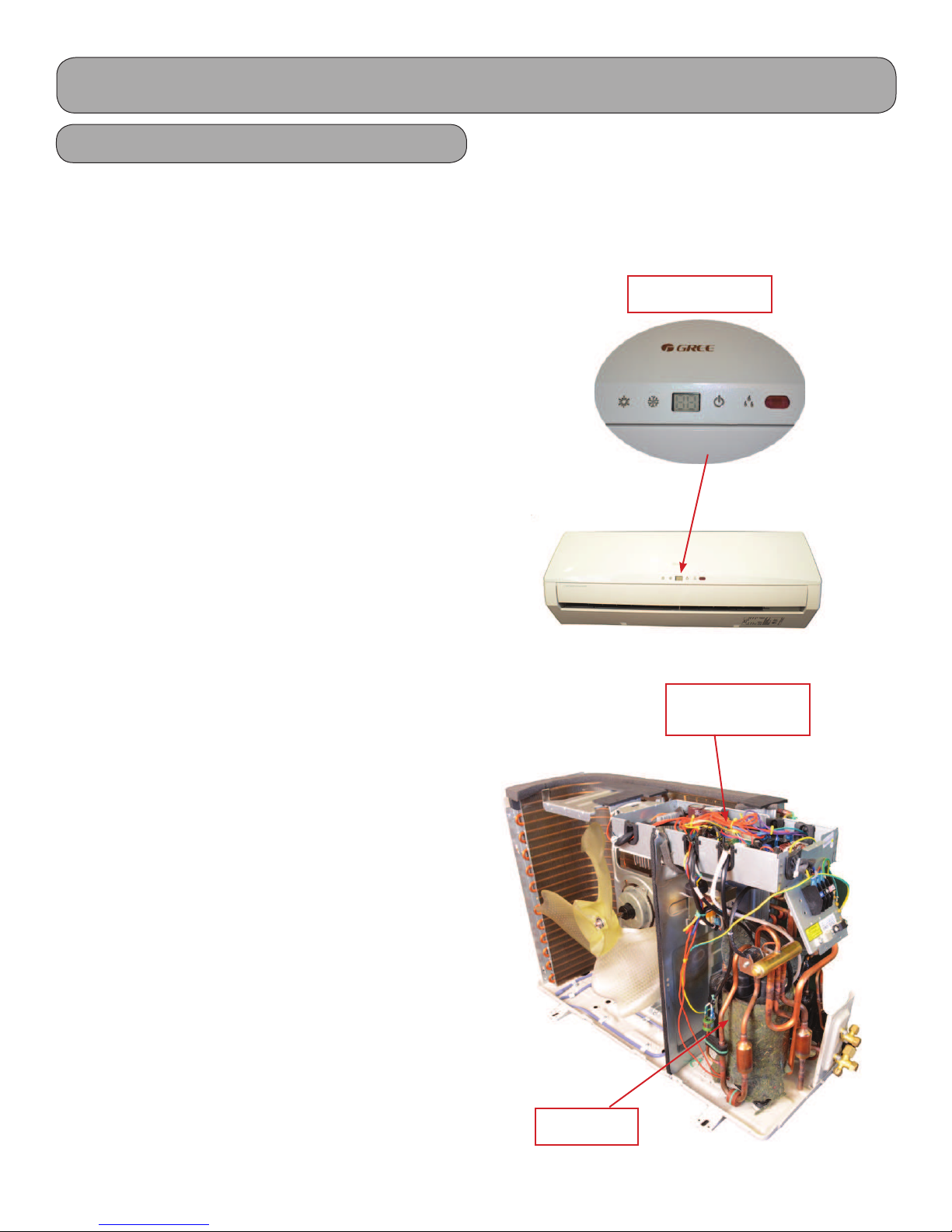
Indoor Display
e indoor unit contains a digital display, which will
indicate the current fault. e evaporator, swing motors, fan motors and circuit board are also components
of the indoor unit. e indoor units have a bypass
switch to bypass the remote control if lost or batteries
fail. is will be explained later in this service manual.
e systems require R410A and are pre-charged for 25’
of lineset. Please refer to your installation manual for
additional charge for linesets longer than 25’.
e systems use a PVE oil and should require no additional oil. All Terra units utilize an Oil Return Mode
which will return oil to the compressor should the
need arise.
Circuit Board with
G10 Technology
Compressor
7
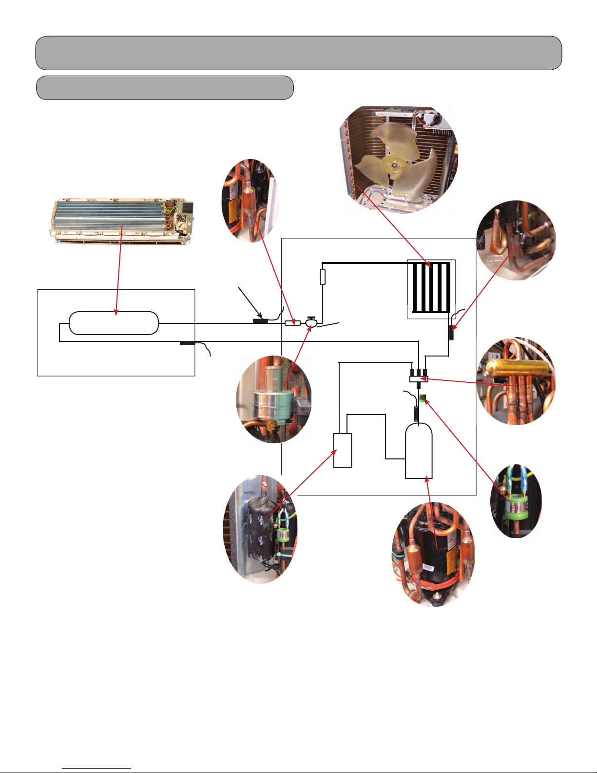
Product Introduction
Refrigeration Components
Indoor Unit
Heat Exchanger
Strainer
Temperature
Sensor
Outdoor Unit
Heat
Exchanger
Temperature
Sensor
Accumulator
Note;
Component locations may vary depending on models.
Compressor
Inverter
Compressor
4-way
High
Pressure
Switch
8
Indoor Unit
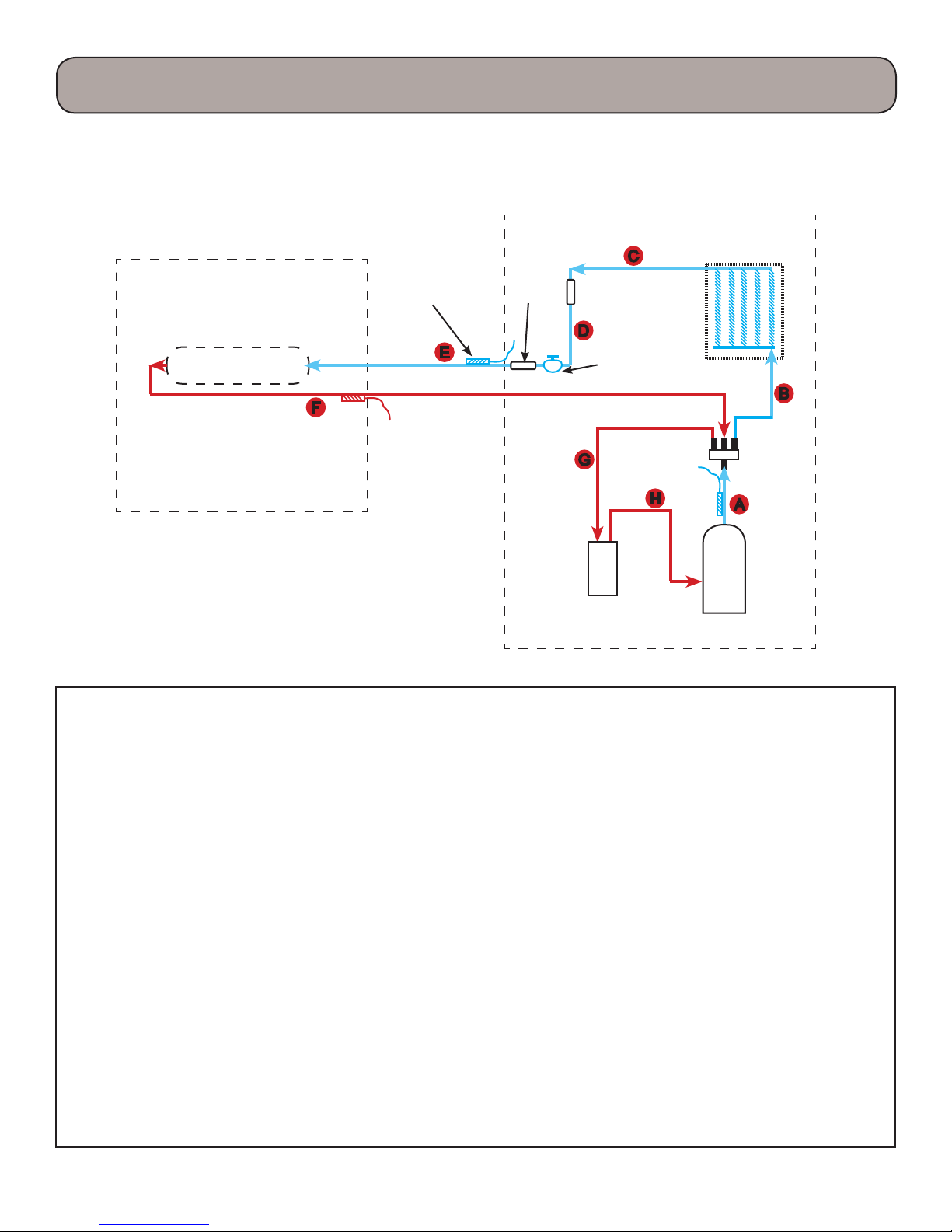
Product Introduction
Cooling Mode
Outdoor Unit
Heat Exchanger
Temperature
Sensor
Filter
Electronic
expansion
Accumulator not
on all sizes
Heat
Exchanger
valve
4-way
valve
Compressor
Inverter
A. Hot gas is discharged from the compressor. e temperature of the gas in monitored by the Discharge Tem-
perature sensor and sent to the outdoor control panel.
B. e hot gas is directed through the 4-way valve, then enters the outdoor coil. e hot gas will be slightly sub-
cooled, however there are no pressure ports to take measurements.
C. e subcooled liquid will enter the lter to remove contaminates.
D. e subcooled liquid will enter the Electronic Expansion Valve (EEV) and will be regulated to about a 10 de-
gree F superheat level. e EEV will adjust its ow based upon the temperature sensor readings. e adjust-
ment process and compressor speed are controlled by the outdoor circuit board.
E. e refrigerant leaving the EEV will be in a low pressure/temperature saturated state. is cold saturated re-
frigerant will move through the coil absorbing heat. is liquid will ash to a vapor and will be superheated
to about 10 degrees F. Since this tubing is cold, it must be insulated.
F. e superheated vapor in returned to the outdoor unit’s 4-way valve.
G. e refrigerant will ow to the accumulator (not all models will have an accumulator) where liquid and
vapor are separated.
H. e refrigerant will ow to the compressor and complete another refrigeration cycle.
e control board will monitor the temperature and pressures and adjust the frequency of the compressor and
ow rate of the EEV as needed. ere are no pressure charts to evaluate temperature or pressures.
9
Indoor Unit
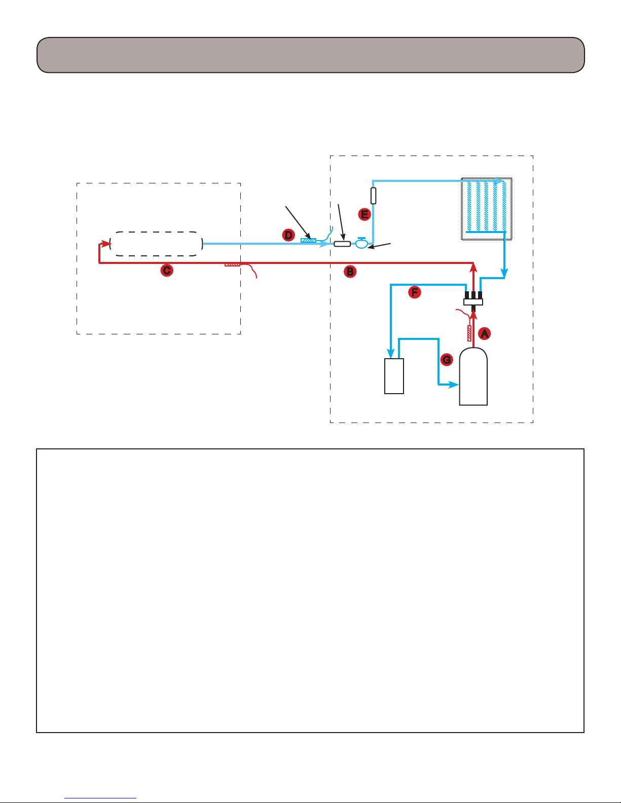
Product Introduction
Heating Mode
Outdoor Unit
Heat Exchanger
Temperature
Sensor
Filter
Electronic
expansion
Accumulator not
on all sizes
Heat
Exchanger
valve
4-way
valve
Compressor
Inverter
A. Hot gas is discharged from the compressor. e temperature of the gas in monitored by the Discharge Tem-
perature sensor and sent to the outdoor control panel.
B. e hot gas is directed through the 4-way valve to the indoor coil making the line a hot gas line.
C. e hot gas will enter the indoor coil and condense to a saturated mix as it travel through the coil and will be
slightly subcooled.
D. e refrigerant returns to the outdoor unit through the lter, then trough the EEV reducing the refrigerant
to a low pressure liquid and will maintain 10 degrees F of superheat.
E. e cold refrigerant will travel through the outdoor coil (evaporator) and will pickup heat from the outdoor
air. is will cause the cold saturated refrigerant to ash to a saturated mixture which will be superheated to
10 degrees F.
F. e superheated vapor will travel through the 4-way valve to the accumulator which will prevent liquid
oodback.
G. e superheated gas will enter the compressor for another refrigeration cycle.
e control board will monitor the temperature and pressures and adjust the frequency of the compressor and
ow rate of the EEV as needed. ere are no pressure charts to evaluate temperature or pressures.
10
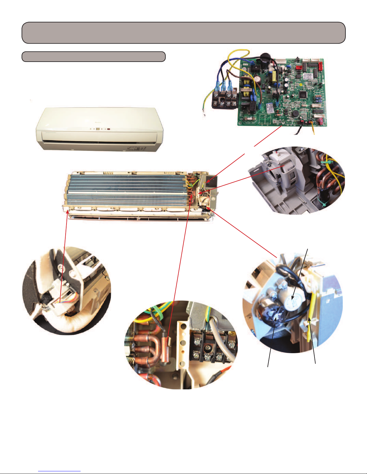
Product Introduction
Indoor Unit Components
Terra 9,000 btuh Indoor Unit
Other Terra models may very slightly.
Indoor Circuit
Board
Horizontal Swing Motor
Indoor Tube ermistor
Fan Motor
Vertical Swing
Motor
Step Motor
Ambient
Temperature
Sensor
11
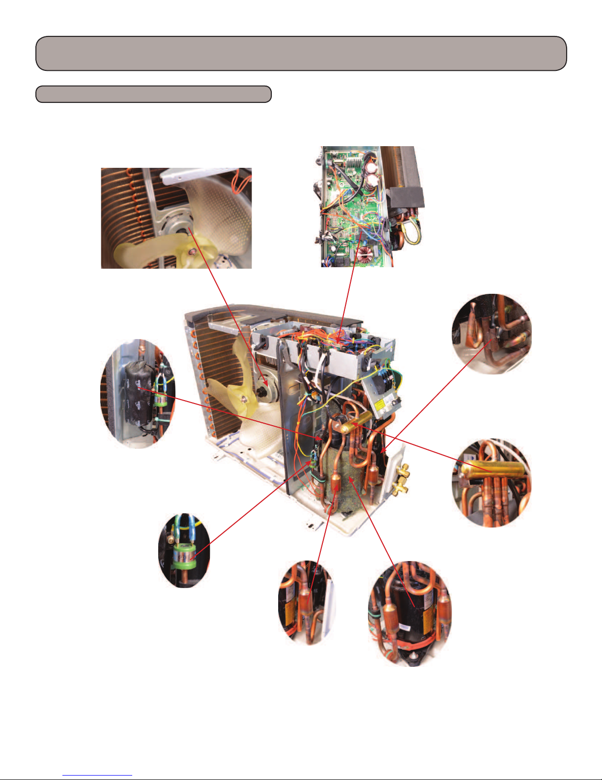
Product Introduction
Outdoor Unit Components
Terra 9,000 btuh Outdoor Unit
Other Terra models may very slightly.
Outdoor Fan
Accumulator
Circuit Board
Temperature
Sensor
4-way
High
Pressure
Switch
Note;
Component locations may vary depending on models.
12
Strainer
Compressor
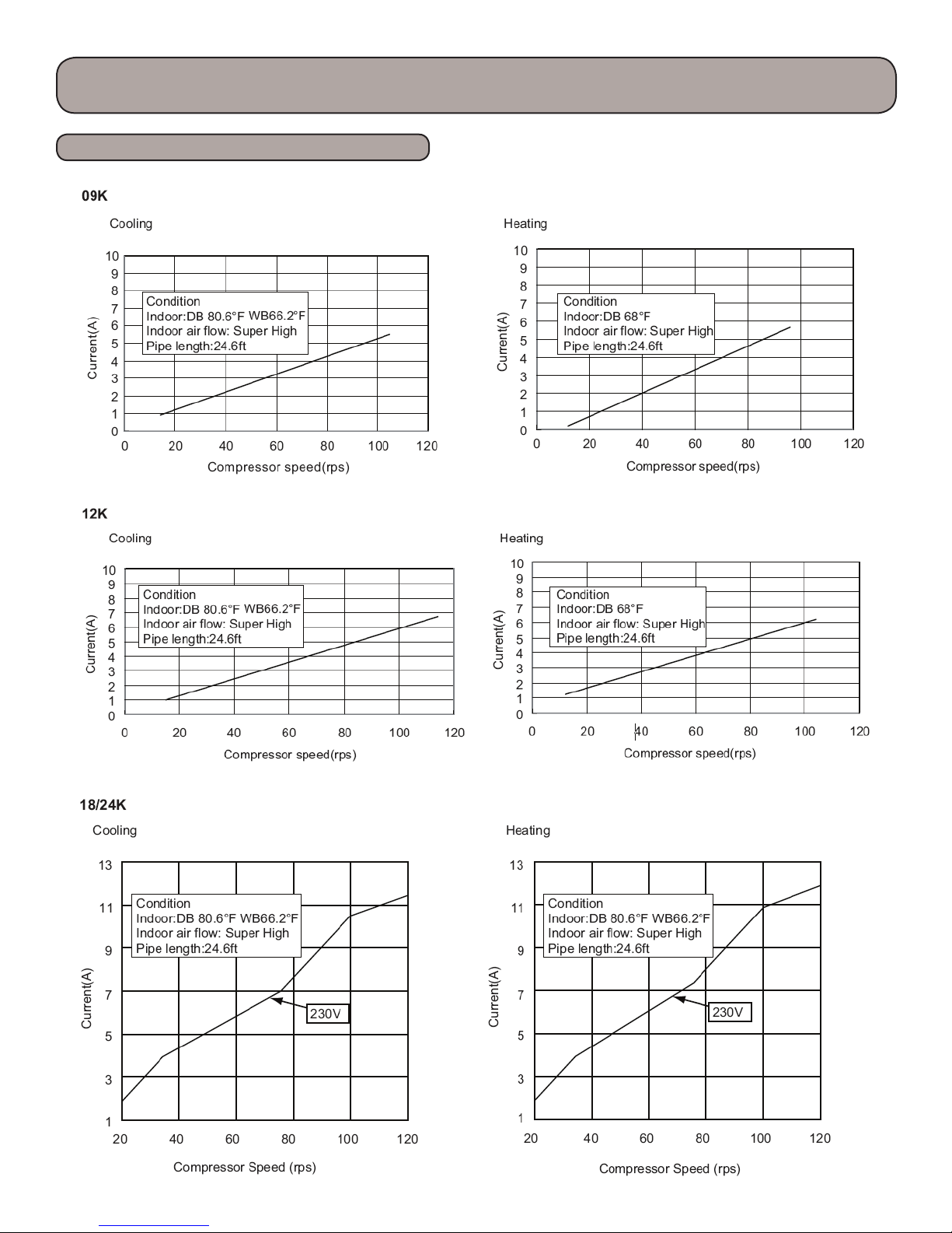
Product Introduction
Operation Characteristic Curve
13
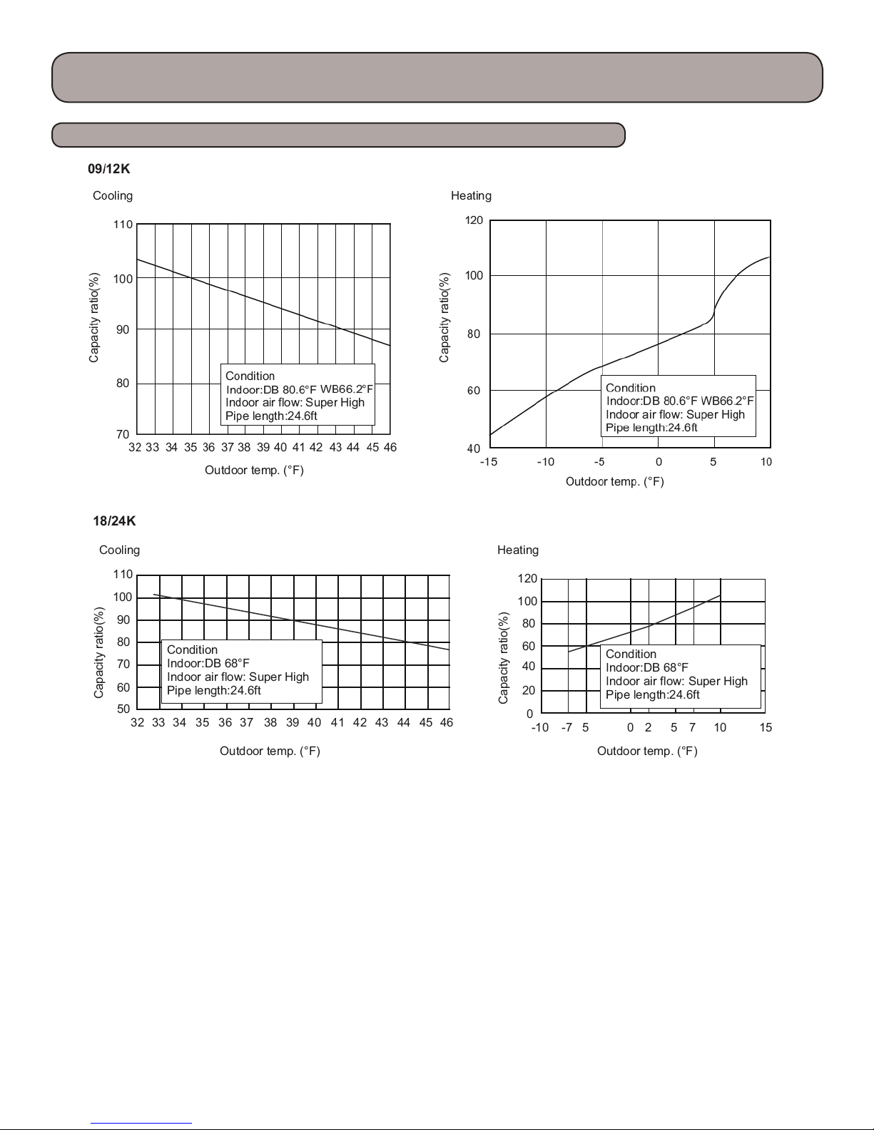
Product Introduction
Capacity Variation Ratio According to Temperature
14
Cooling
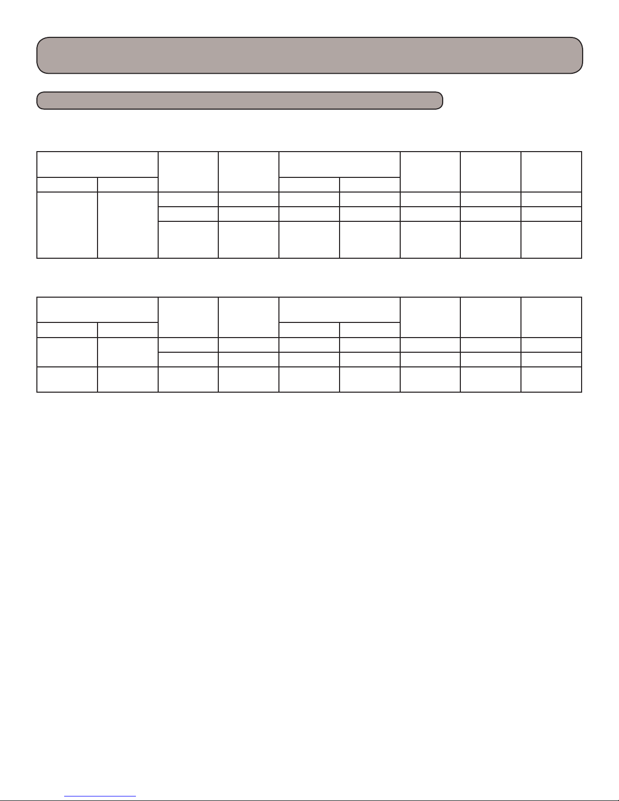
Product Introduction
Operation Data
Temperature Condition (OF)
Indoor Outdoor T1 (
80.6/66.6 95/75.2
Model
9K 135 57.2 98.6 Turbo High 46
12K 152 59 98.6 Turbo High 70
18/24K 131-160
Pressure
(PSI)
Heat Exchanger
Pipe Temperature
O
F) T2 (OF)
46.4-51.8 to
51.6-57.2
Indoor Fan
Mode
167-181.4 to
98.6-118.4 Turbo High 75
Outdoor Fan
Mode
Heating
Temperature Condition (OF)
Indoor Outdoor T1 (
70/60 47/43
68/59 44.6/42.8 18/24K 319-348
Model
9K 401 113 41 Turbo High 56
12K 308 107.6 41 Turbo High 73
Pressure
(PSI)
Notes:
(1) Measure surface temperature of heat exchanger pipe around center of heat exchanger path U-Bend.
(2) Length of connecting tubing = 24.6 .
(3) P = Pressure PSI
T1 = Inlet and Outlet Temperature for Evaporator
T2 = Inlet and Outlet Temperature for Condenser
Heat Exchanger
Pipe Temperature
O
F) T2 (OF)
167-181.4
98.6-113
33.8-37.4 to
35.6-42.8
Indoor Fan
Mode
Turbo High 75
Outdoor Fan
Mode
Compressor
Speed
(rps)
Compressor
Speed
(rps)
15
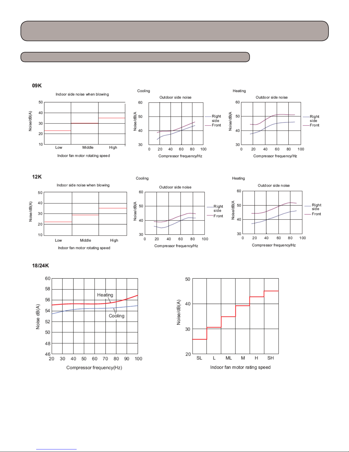
Product Introduction
Noise Criteria Curve Tables
16

Product Introduction
System Operation 9,000/12,000 btuh Models
Basic Functions
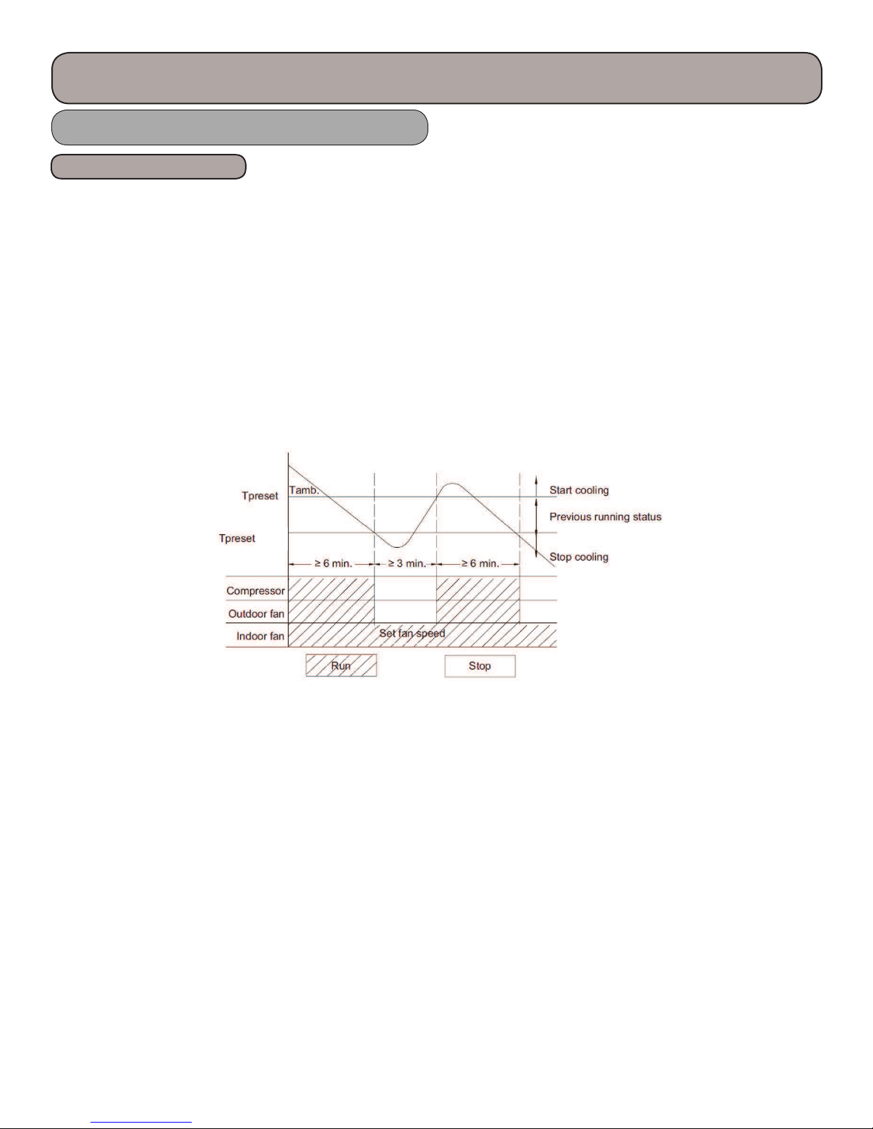
e compressor should stay o for at least 3 minutes before starting the unit. e compressor circuit has a 3 minute delay if
the compressor is de-energized during a run cycle. If the compressor starts from a de-energized cycle, there will be no time
delay. e compressor has a minimum runtime of 6 minutes regardless of room temperature.
1) Cooling Mode
Cooling Process
When the indoor ambient rises 2 F above the preset temperature, the unit will start the cooling cycle. e outdoor fan
and compressor will start. e indoor fan will run continuously at the selected speed. e outdoor unit will monitor the
appropriate temperatures and pressure and adjust the compressor speed and the EEV as required. If the indoor ambient is
> 2 F then the preset temperature, the compressor will increase the frequency; < 2 F the compressor will begin reducing
the frequency. e G10 technology will control compressor speed based on indoor load and compressor amperage. When
the indoor temperature is satis ed, the compressor will stop, then 30 seconds later the outdoor fan will stop.
Evaporator Freeze Protection
e so ware will monitor the indoor evaporator coil form freezing.
e following will occur 6 minutes a er the compressor has been operating in the cooling or dry mode:
If the evaporator temperature drops below 36 F, the compressor will operate at a reduced frequency. If the evaporator
is below 30 F for 3 minutes, the compressor will stop, 30 seconds later the outdoor fan will stop. In cooling mode, the
indoor fan and swing motor will remain on. If the evaporator temperature is >= 50 F and the compressor is o for at least
3 minutes, the compressor will resume its normal operation state.
Overcurrent Protection
e so ware will monitor the compressor current to maintain it in a safety and reliable operating range.
If the total current <= 6 amps, the compressor speed frequency is allowed to increase. If the current >= 7 amps, the
compressor speed frequency will not increase. If the total current >= 8 amps, the unit will operate and decrease the
compressor speed. If the current >= 9 amps, the compressor will stop and the indoor fan will stop a er 30 seconds.
2) Dry Mode
Drying Process
is feature will not take the place of a dehumidi er, it is intended to dry the ler and slightly cool the air. If the indoor
ambient temperature is greater than the preset temperature, the unit will enter the cooling and drying mode, in which
case the compressor will operate and the indoor fan will run at a low speed. When the indoor ambient temperature is at or
below the preset temperature, the unit will operate in it previous running state. When the indoor ambient drops to more
than 2 F below the preset temperature the compressor will stop running, then 30 seconds later the outdoor fan will stop,
the indoor fan will run at low speed.
- 2 F
17
Product Introduction
System Operation 9,000/12,000 btuh Models, cont.
Basic Functions
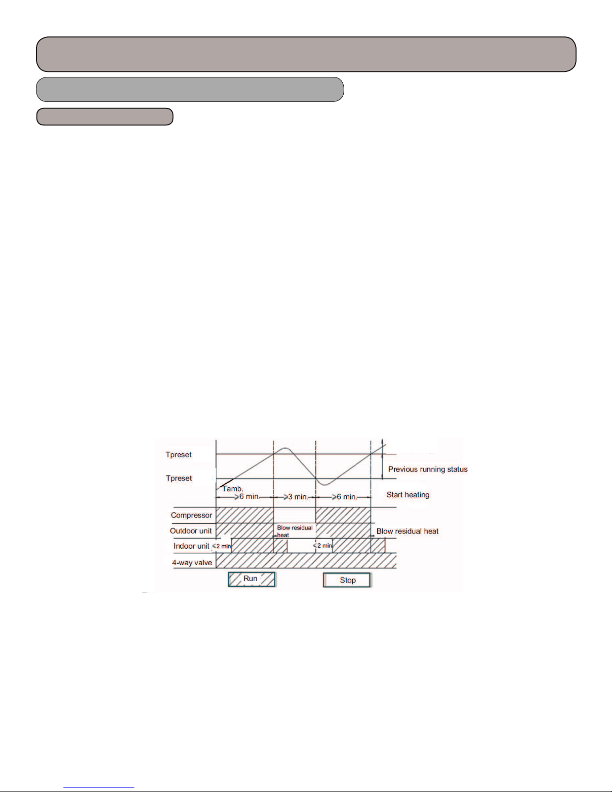
3)Heating Mode
Heating Process
When the indoor ambient drops 2 F below the preset temperature, the unit will start the heating cycle. e outdoor fan,
compressor and 4-way valve will operate. e indoor fan will operate in the “Cold Air Prevention” mode in which the
indoor fan will have a 2 minute delay a er the call for heating. e indoor evaporator coil temperature must reach 104 F
before the indoor fan will start, this will prevent cold air from discharging from the indoor coil. When the indoor evaporator coil temperature is > 104 F, the indoor fan will operate at low speed for 1 minute. With 1 minute of operation or 2
minutes of no fan operation and the indoor evaporator coil temperature is > 108 F, the indoor fan will operate at its preset
condition.
If the indoor ambient temperature is < 9 F and > 2 F of the preset temperature, the unit will run in its original mode of
operation.
If the compressor is running and the mode is changed from cooling to heating, the 4-way valve will be energized 2-3 minutes later.
If the indoor ambient temperature is >= 9 F than the preset temperature, the compressor will stop and the outdoor fan will
stop a er a 30 second delay. e indoor fan will continue to operate at its preset mode.
e G10 technology will determine compressor frequency based on ambient temperatures.
+9 F
+ 2 F
Stop heating
18

Product Introduction
System Operation 9,000/12,000 btuh Models, cont.
Basic Functions
Defrost Process
1) e unit will enter defrost when the following conditions are met:
A. Outdoor ambient <= 41 F
B. Compressor had accumulated more than 3 hours of operation in heating mode
C. e outdoor coil <= 32 F
Note: e compressor runtime will be cleared when the outdoor ambient is > 41 F or when the compressor has started
up a er changing to cooling or drying mode and defrost has nished. e runtime will not be cleared when the unit has
stopped a er reaching the setpoint temperature, a protection fault or changing to fan mode.
ere are 3 perimeters used in the defrost algorithms, Outdoor ambient(T
a calculated T
T
compensation
D. A er power-up, for the rst defrost T
E. T
F. T
compensation
is calculated by the following:
tube > 36 F then T
outdoor
tube <= 36 F then T
outdoor
compensation = 32
compensation = 32
compensation = 37
F
F
F
ambient), Outdoor tube(T
outdoor
outdoor
tube) and
2) When heating has operated continuously for 45 minutes, or accumulated for 90 minutes, the unit will enter defrost
mode in 3 minutes a er meeting any of the conditions below:
A. Outdoor ambient >= 41 F and outdoor coil <= 28 F
B. 28 F <= T
C. 23 F <= T
D. 14 F <= T
ambient< 41 F, T
outdoor
ambient < 28 F <= T
outdoor
ambient < 23 F , T
outdoor
outdoor
outdoor
outdoor
tube <= 21 F
tube <= 18 F
tube -T
compensation
<= (T
ambient - 37 F)
outdoor
3) During defrost, if run time for the compressor does not reach 3 minutes, the defrost cycle will not start for the next 2
hours. At that time the compressor stops operation and 30 seconds later the outdoor fan will stop. 30 seconds a er this the
4-way reversing valve will de-energized. Following another 30 second delay, the compressor will increase its compressor
speed for defrosting. Defrosting will last for 450 seconds or until the T
tube >= 50 F, at this temperature the compres-
outdoor
sor will decrease it compressor speed for 30 seconds, then will stop. In another 30 seconds the 4-way valve will energize,
the 60 seconds later the compressor and outdoor fan will start. e compressor speed for defrosting will be 85hz.
During Defrost mode, a “H1” will be displayed on the indoor front panel display indicating the user selected mode has
been overridden and the system is performing a outdoor coil defrost operation.
19

Product Introduction
System Operation 9,000/12,000 btuh Models, cont.
Basic Functions
System Protection
Cold Air Prevention (Heating mode with compressor running)
e system guards against discharging cold air in heating mode. It will delay the indoor fan until the evaporator coil has
warmed up to discharge warm, comfortable air into the room.
1) When the T
ambient < 75 F and the T
indoor
to run at low speed a er a 2 minute delay. is will reduce cold air upon heating startup. Within 2 minutes, if
T
tube > 104 F, the indoor fan will run at low speed. A er 1 minute of operation, the fan will run at the preset fan
indoor
mode. Within 1 minute of low speed operation or 2 minutes of no fan operation, with the T
run at the preset mode.
tube <= 104 F with the fan in a stopped state, the indoor fan will begin
indoor
tube > 108 F, the fan will
indoor
2) If the T
at the preset mode. A er 1 minute of low speed operation, if the and the T
ambient >= 75 F and the T
indoor
tube <= 108 F the indoor fan will run at low speed for 1 minute than run
indoor
tube > 108 F the fan will operate at its
indoor
preset mode.
Note:
e T
Overcurrent and Speed Protection (Total Current = I
ambient in 1 & 2 above refers to the unit going into the heating mode coming out of defrost.
indoor
)
total
e so ware will monitor the compressor current draw and adjust the compressor speed in order to maintain the inverter and
compressor in a safety and reliable operating range.
A. If I
B. If I
C. If I
D. If I
<= 6, an increase in frequency will be allowed
total
>= 7, increasing the frequency is not allowed.
total
>= 8, the compressor will decrease its frequency
total
>= 9, the compressor will stop and the indoor fan will stop a er 30 seconds.
total
4)Fan Mode
Under this mode, the fan will run at the preset speed and the outdoor fan, compressor and 4-way valve will stop.
5)Auto Mode
Auto Mode Process
Setting the auto mode will run the unit in heat or cool automatically depending on T
1)Operating Parameters
A. If the T
B. If the T
C. When the T
ambient >= 79 F the unit will operate in cooling mode. e set temperature is 77 F.
indoor
ambient <= 72 F the unit will operate in heat mode. e set temperature is 68 F.
indoor
ambient <= 73 F and >= 77 F, the unit will operate in the previous state. If it is energized
indoor
for the rst time, it will run in Fan mode
D. In auto mode, the cooling frequency will be the same as the cooling only mode and the heating frequency will
be the same as the heating only mode.
2) Protection
A. In cooling operation, protection is the same as the cooling only mode
B. In heating operation, protection is the same as the heating only mode
C. When the indoor ambient temperature changes, the operation mode will be automatically selected. Once started
the compressor will have a 6 minute runtime.
20
indoor
ambient

Product Introduction
System Operation 9,000/12,000 btuh Models, cont.
Basic Functions
6)Common Protection Functions and Fault Displays
Coil High Temperature Protection
= measured temperature of outdoor coil in cooling mode, measured temperature of indoor coil in heating mode.
T
tube
1) Outdoor Coil High Temperature Protection - In cooling mode the so ware will monitor the outdoor coil for an abnor-
mal high temperature condition.
A. If T
B. If T
C. If T
D. If T
2) Indoor Coil Temperature Protection - In heating mode the so ware will monitor the indoor coil for an abnormal high
temperature condition.
A. If T
B. If T
C. If T
D. If T
<= 126 F, the unit will return to its original operation state
tube
>= 131 F, frequency rise is not allowed
tube
>= 136 F, the compressor will run at reduced frequency
tube
>= 144 F, the compressor will stop and the indoor fan will operate at preset speed
tube
<= 122 F, the unit will return to its original operation state
tube
>= 127 F, frequency rise is not allowed
tube
>= 133 F, the compressor will run at reduced frequency
tube
>= 140 F, the compressor will stop and the indoor fan will blow residual heat and then stop
tube
3) Compressor Discharge Temperature Protection
e so ware will monitor the compressor discharge for an abnormal high temperature condition.
A. If T
B. If T
C. If T
D. If T
>= 208 F, frequency rise is not allowed
tube
>= 217 F, the compressor will run at reduced frequency
tube
>= 230 F, the compressor will stop
tube
<= 194 F and the compressor has been off for at least 3 minutes, the compressor will resume operation
tube
Communication Fault
If the unit fails to receive correct signals for a 3 minutes, communication fault will occur and the whole system will stop
and a “E6” will be displayed on the front panel of the indoor unit.
Module Protection
Under module protection mode, the compressor will stop. When the compressor remains o for 3 minutes, the compressor will resume operation. If the module protection occurs six time in succession, the compressor will remain o . is is a
thermal protection for the indoor module (AP1).
Compressor Protection
e compressor contains a thermal overload switch tom protect it from abnormal conditions.
If temperature sensed by the overload sensor is over 239 F, the compressor will stop and the outdoor fan will stop a er 30
seconds. When the temperature is below 203 F, the overload protection will reset to normal state.
DC Buss Voltage Protection
e so ware will monitor the DC bus voltage.
If voltage on the DC Bus is below 150 or over 420v, the compressor will stop and the outdoor fan will stop in 30 seconds.
When the voltage on the DC bus returns to normal and the compressor has been o for 3 minutes, the compressor will
resume its operation.
21

Product Introduction
System Operation 9,000/12,000 btuh Models, cont.
Other Controls
1)On/O
e on-o state will change with each button press.
2)Mode Selection
Press the “Mode” button to change from Auto, Cool, Dry, Fan or Hesat Pump
3)Temperature Setting
Each time you press the “TEMP+” or “TEMP-” button the temperature setting will change by 1 F. e temperature range
is 60.8 F - 86 F. In Auto Mode this button will not function.
4)Time Switch
e unit will stop and start by setting the Timer on the remote controller.
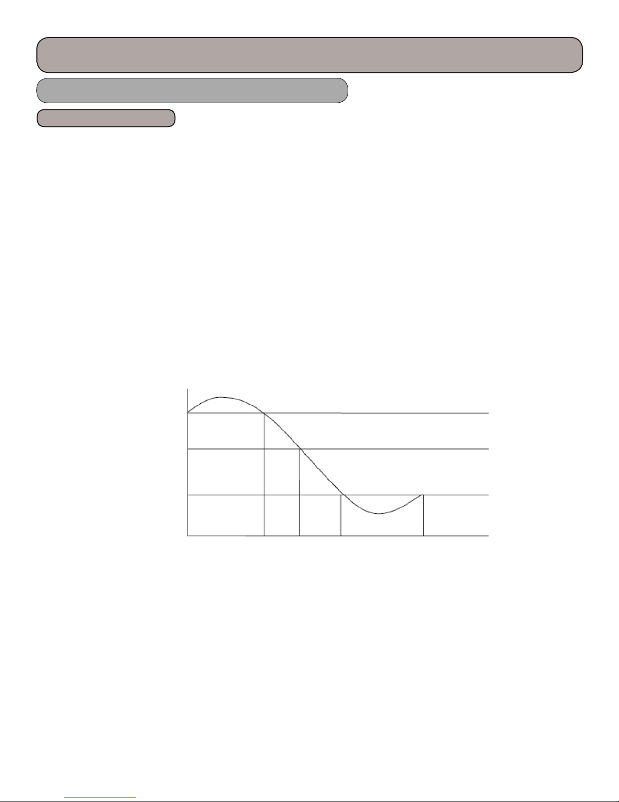
5)Energy Savings Mode (Press Temp & Clock simultaneously, display will indicate “SE”)
In heating mode, refer to the Cold Air Prevention explained in the (3)Heating Mode process .
In cooling mode, the fan speed will adjust according to the fan speed curve below:
T
amb.
88 F
T
+ 3 F
preset
T
+ 1 F
preset
Fan Speed
Turbo
High Med. Low
22
Product Introduction
System Operation 9,000/12,000 btuh Models, cont.
Other Controls
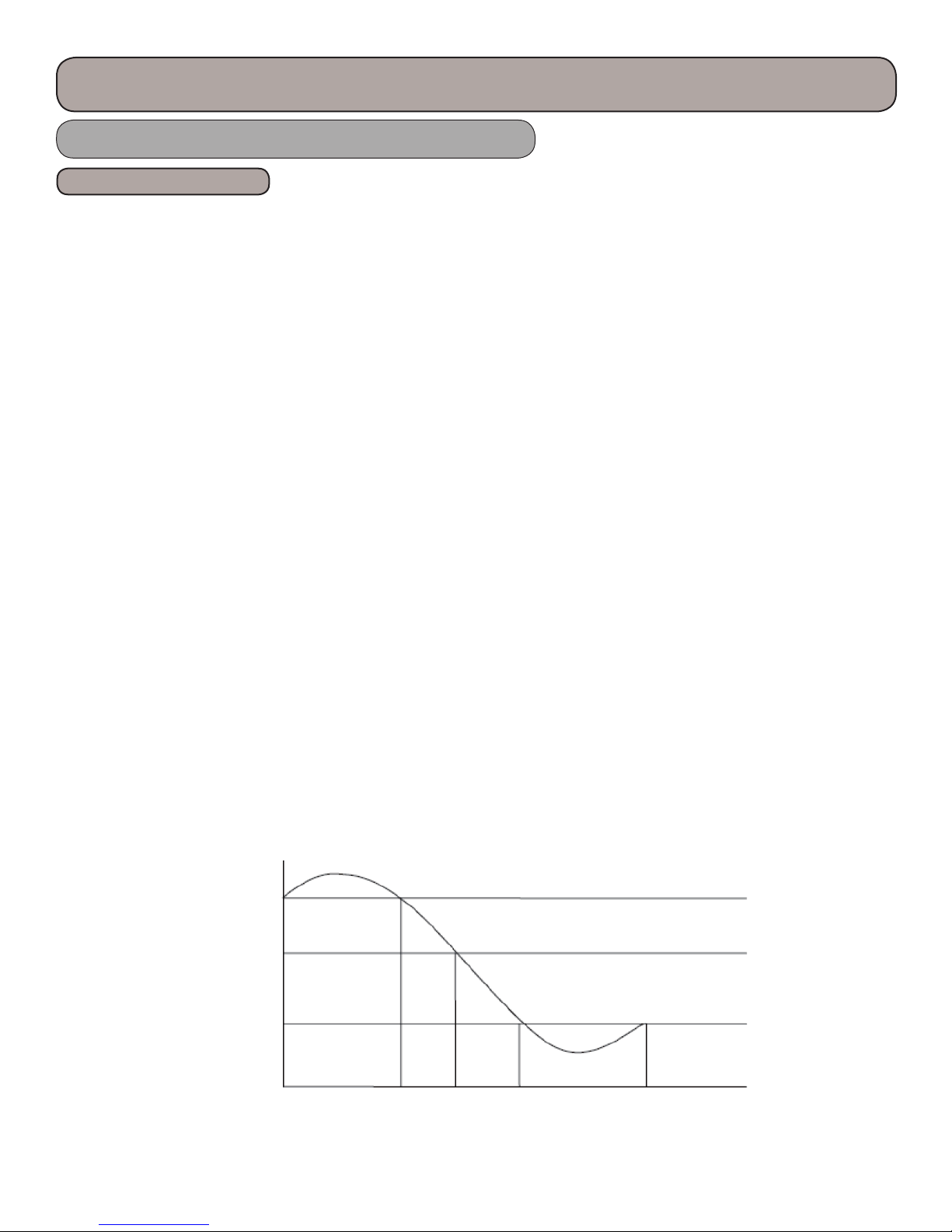
6)Sleep Control
e Terra has 3 Sleep mode settings to improve comfort and energy savings.
Auto Mode and Fan Mode do not utilize the Sleep Mode Settings
Sleep Mode 1 (Gradual Cycle)
1. Cool or Dry Mode
a) A er 1 hour of operation the temperature setting will raise 2 F
b) A er 2 hours of operation the temperature setting will increase 4 F and stay at this setting until the
sleep mode in canceled
2. Heat Mode
a) A er 1 hour of operation the temperature setting will decrease 2 F
b) A er 2 hours of operation the temperature setting will decrease 4 F and stay at this setting until the
sleep mode in canceled
T
amb.
87.8 F
T
+ 5.4 F
preset
T
+ 1.8 F
preset
Fan Speed Super High High Med Low
23

Product Introduction
System Operation 9,000/12,000 btuh Models, cont.
Other Controls
Sleep Mode 2 (Adaptive Cycle)
1. Cool or Dry Mode (Initial setpoint between 61 F. - 74 F.)
a) A er 1 hour of operation the temperature setting will raise 2 F every hour
b) A er 3 hours of operation the temperature setting will raise 6 F above initial setpoint and stay at this
setting
c) A er 7 hours of operation, the setpoint will move to 4 F. above the initial setpoint and remain until the
sleep mode in canceled.
Cool or Dry Mode (Initial setpoint between 75 F. - 81 F.)
a) A er 1 hour of operation the temperature setting will raise 2 F every hour
b) A er 3 hours of operation the temperature setting will raise 4 F above initial setpoint and stay at this
setting
c) A er 7 hours of operation, the setpoint will move to 2 F. above the initial setpoint and remain until the
sleep mode in canceled.
Cool or Dry Mode (Initial setpoint between 82 F. - 85 F.)
a) A er 1 hour of operation the temperature setting will raise 2 F every hour
b) A er 3 hours of operation the temperature setting will raise 24 F above initial setpoint and stay at this
setting
c) A er 7 hours of operation, the setpoint will move back to the initial setpoint and remain until the
sleep mode in canceled.
Cool or Dry Mode (Initial setpoint above 85 F.)
a) e original setpoint will be maintained for 7 hours, then a er 7 hours it will decrease by 1 F until the
sleep mode is canceled
2. Heat Mode (Initial setpoint 61 F.)
a) e unit will maintain this setpoint until Sleep Mode is canceled
Heat Mode (Initial setpoint between 62 F. - 68 F.)
a) A er 1 hour of operation the temperature setting will decrease 2 F and maintain this setpoint until
Sleep Mode is canceled
Heat Mode (Initial setpoint between 69 F. - 81 F.)
a) A er 1 hour of operation the temperature setting will decrease 2 F and maintain this setpoint until
Sleep Mode is canceled
Heat Mode (Initial setpoint between 82 F. - 86 F.)
a) A er 1 hour of operation the temperature setting will decrease 2 F every hour
b) A er 3 hours, the setpoint will be xed at 6 F below the initial setpoint and remain at this setpoint until
Sleep Mode is canceled
24
Product Introduction
System Operation 9,000/12,000 btuh Models, cont.
Other Controls
Sleep Mode 3 (Customized Cycle)
You will be required to enter 8 room setpoint values for 8 hours of runtime. e last room setpoint value will be maintained until Sleep Mode is canceled.
In Sleep Mode 3, press the “Turbo” button to enter setup mode. e remote controller will display “1:00” in the time location. Use the “+” and “-” buttons to select the desired room setpoint for the 1st hour of runtime, then press the “Turbo”
button to save the data.
e remote controller will display “2:00”. Once again, use the “+” and “-” buttons to select the desired room setpoint for the
second hour of run time. Press the “Turbo” button to save the data.
Repeat this procedure for the remaining hours (total of 8). A er all 8 settings have been saved, the remote controller will
automatically revert back to the standard time and temperature display.
At anytime, you may press the “ON/OFF”, “MODE”, “TIMER”, “SLEEP” or “TURBO” buttons to cancel the Sleep Mode 3
7)Indoor Fan Control
e indoor fan can be set to Ultra High, High, Med, Low and Auto with the remote controller.
In auto mode, the following speeds will be set:
Cooling Mode
a) T
b) T
c) T
ambient >= T
indoor
- 2 F < T
setpoint
ambient <= T
indoor
T
preset
T
+ 2 F
preset
indoor
+ 2 F, fan will run on high speed
setpoint
ambient < T
- 2 F, fan will run on low speed
setpoint
T
amb.
+ 2 F, fan will run on medium speed
setpoint
T
-2 F
preset
Fan Speed High Med. Low O
25

Product Introduction
System Operation 9,000/12,000 btuh Models, cont.
Other Controls
Fan Only “Auto” Mode
a) T
b) T
c) T
ambient > T
indoor
+ 2 F <= T
setpoint
ambient < 2 F of T
indoor
T
T
preset
preset
T
setpoint
+ 4 F
preset
-2 F
+ 4 F, fan will run on high speed
ambient <= T
indoor
setpoint,
T
amb.
setpoint
fan will run on low speed
+ 4 F, fan will run on medium speed
Fan Speed High Med. Low O
Dry Mode
e indoor fan will be set to low speed.
Heating Mode
a) T
b) T
c) T
ambient <= T
indoor
+ 1 F < T
setpoint
ambient >= T
indoor
T
T
preset
preset
T
indoor
+ 5 F
preset
+1 F
setpoint
setpoint
+ 1 F, fan will run on high speed
ambient < T
+ 2 F, fan will run on low speed
T
amb.
+ 5 F, fan will run on medium speed
setpoint
Fan Speed
26
O
Low
High Med.
Product Introduction
System Operation 9,000/12,000 btuh Models, cont.
Other Controls
8) Buzzer Control
e buzzer control will send a “Tone” when the air conditioner is powered-up or received information sent by the remote
control. You will also hear the tone when there is a button input or if the indoor unit doesn’t receive a signal from the remote controller in the Heat Mode.
9) Auto Button (Manual Override) - Located on indoor unit.
In the event the controller is missed placed or the batteries are defective, this will override the remote controller. If the controller is on, pressing this button will stop it, if it is
o , pressing the button will turn the controller on. When turning the controller on, the
swing and light will be on and the unit will run based on the remote controller setting.
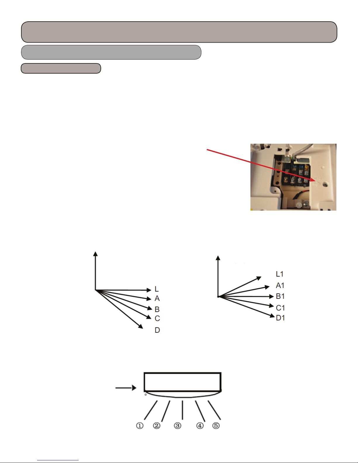
10) Swing Control
Vertical Swing
During power-up, the vertical swing motor will move the horizontal louver counter clockwise and close the air de ector.
In Heating and Auto/Heat mode, the air de ector will move to position “D” if no swing mode is set. In Cooling mode the
louver will move to L1. All other positions can be set by pressing the appropriate button to change the swing location.
Heating Angle Cooling Angle
Horizontal swing
During power-up, the vertical louver will be reset to the start position and then stop in the middle position. ere are 7
positions that the horizontal swing can be set including automatic swing and stopping between position 1 & 5.
0
0
0
0
27

Product Introduction
System Operation 9,000/12,000 btuh Models, cont.
Other Controls
11) Display
1. Operational and Mode Display
All the display patterns will display for a time when the power is on, the operation pattern will display in red under standby
status. When the unit is started by the remote controller, the indication pattern will light and display the current operation.
You can turn o the display by pressing the “Light” button on the remote controller.
2. Indoor Unit Display
Depending on the settings on the remote controller, the Indoor Unit LED display may display the current temperature
setpoint and indoor ambient temperature. “H1” will be displayed during the defrost cycle.
12)Drying Function (XFan)
e indoor fan will run for 10 minutes a er the unit is turned o (cooling or dry modes only) to ensure that additional
moisture is removed from the coil.
13)Power-O Memory Function
Upon a power failure the mode of operation, swing function, light, set temperature and fan speed will retain memory. e
unit will restart when recovering from a power interruption to the memory saved before the interruption occurred. If the
power interruption occurs during a timed mode, the time le will not be remembered and will start to recount from the
beginning. ere will be a 3 minute compressor delay before resuming.
14)Outdoor Compressor and Condenser Heating Band Control
Under normal conditions, the control logic of the Electric Heating Bands will be as follows:
1. Control of Compressor Electric Heating Band
a) Conditions for startup: e compressor is o and outdoor ambient <= 23 F
b) Conditions for turning o : Compressor operating, Compressor o and outdoor ambient >= 28 F
c) Band will turn o if the outdoor ambient temperature sensor has a malfunction.
2. Control of Condenser Electric Heating Band
a) Condenser Band will be on if the Outdoor Ambient <= 34 F
b) During defrost operation, the heater band will operate 3 minutes a er the compressor starts operating. When
the compressor has operated for 3 minutes and the outdoor ambient >= 38 F, the band will be de-energized.
c) Electric band will be de-energized when the outdoor ambient >= 38 F
d) When 34 F < outdoor Ambient < 38 F, the electric heater band will keep it’s previous status.
If the outdoor sensor has a malfunction, the Electric Heating Band will be de-energized. It will have a 2 minute delay before it can be started again.
28
Product Introduction
System Operation 18,000/24,000 btuh Models
Basic Functions
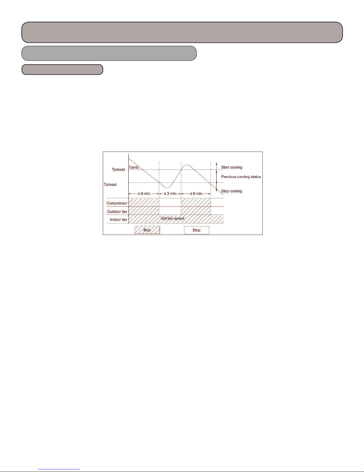
e compressor should stay o for at least 3 minutes before starting the unit. e compressor circuit has a 3 minute delay if
the compressor is de-energized during a run cycle. If the compressor starts from a de-energized cycle, there will be no time
delay. e compressor has a minimum run time of 6 minutes regardless of room temperature.
1) Cooling Mode
Cooling Process
When the indoor ambient rises 5 F above the preset temperature, the unit will start the cooling cycle. e outdoor fan and
compressor will start. e indoor fan will run continuously at the selected speed. e outdoor unit will monitor the appropriate temperatures and pressure and adjust the compressor speed and the EEV as required. If the indoor ambient is > 5
F then the preset temperature, the compressor speed will increase; < 5 F the compressor will begin reducing it’s speed. e
G10 technology will control compressor speed based on indoor load and compressor amperage. When the indoor temperature is satis ed, the compressor will stop, then 30 seconds later the outdoor fan will stop.
- 5.4 F
Evaporator Freeze Protection
e so ware will monitor the indoor evaporator coil for freezing.
In Cooling or Dry mode, if the Indoor tubes are < 32 F, for 3 consecutive minutes, the compressor will stop. e compressor will start when the tubes are above the calculated temperature limit. If the indoor tubes are < 43 F,
the compressor will adjust it’s speed as needed. If the unit has stopped 6 times repeatedly, the unit will stop and a fault code
will be displayed. e unit will need to be turned o , then back on to reset. As the compressor runs in normal mode, the
number of faults will be cleared, they may also be cleared by switching from fan mode to heat mode.
Overcurrent Protection
e so ware will monitor the compressor current to maintain it in a safety and operating range.
If the total current >= 17 amps, the compressor will stop and the indoor fan will stop a er 30 seconds. e system can
resume a er a 3 minute startup delay.
29
Product Introduction
System Operation 18,000/24,000 btuh Models, cont.
Basic Functions
2) Dry Mode
Drying Process
is feature will not take the place of a dehumidi er, it is intended to dry the ler and slightly cool the air. If the indoor
ambient temperature is greater than the preset temperature, the unit will enter the cooling and drying mode, in which
case the compressor will operate and the indoor fan will run at a low speed. When the indoor ambient temperature is at or
below the preset temperature, the unit will operate in it previous running state. When the indoor ambient drops to more
than 3.6 F below the preset temperature the compressor will stop running, then 30 seconds later the outdoor fan will stop,
the indoor fan will run at low speed.
-3.6 F
Overcurrent Protection (Same as Cooling Mode)
3)Heating Mode
Heating Process
When the indoor ambient drops 2 F below the preset temperature, the unit will start the heating cycle. e outdoor fan,
compressor and 4-way valve will operate. e indoor fan will operate in the “Cold Air Prevention” mode in which the
indoor fan will have a 2 minute delay a er the call for heating. e indoor evaporator coil temperature must reach 104 F
before the indoor fan will start, this will prevent cold air from discharging from the indoor coil. When the indoor evaporator coil temperature is > 104 F, the indoor fan will operate at low speed for 1 minute. With 1 minute of operation or 2
minutes of no fan operation and the indoor evaporator coil temperature is > 108 F, the indoor fan will operate at its preset
condition.
If the indoor ambient temperature is < 9 F and > 2 F of the preset temperature, the unit will run in its original mode of
operation.
If the compressor is running and the mode is changed from cooling to heating, the 4-way valve will be energized 2-3 minutes later.
If the indoor ambient temperature is >= 9 F than the preset temperature, the compressor will stop and the outdoor fan will
stop a er a 30 second delay. e indoor fan will continue to operate at its preset mode.
e G10 technology will determine compressor frequency based on ambient temperatures.
30
 Loading...