

Gree GWH09RB-K3DNA3C/I, GWH09RB-K3DNA2C/I, GWH09RB-K3DNA5C, GWH09RB-K3DNA5C/I, GWH09RB-K3DNA6C Service Manual
...
GREE ELECTRIC APPLIANCES,INC.OF ZHUHAI
Change for Life
Service Manual

Service Manual
Table of Contents
Part
Ⅰ
: Technical Information
......................................................................... 1
1. Summary
........................................................................................................................ 1
2. Specifi cations
............................................................................................................ 4
2.1 Specifi cation Sheet ............................................................................................................. 4
2.2 Operation Characteristic Curve ........................................................................................ 12
2.3 Capacity Variation Ratio According to Temperature ......................................................... 12
2.4 Cooling and Heating Data Sheet in Rated Frequency ..................................................... 13
2.5 Noise Curve ...................................................................................................................... 13
3. Outline Dimension Diagram
........................................................................ 14
3.1 Indoor Unit ........................................................................................................................ 14
3.2 Outdoor Unit ..................................................................................................................... 14
4. Refrigerant System Diagram
...................................................................... 17
5. Electrical Part
........................................................................................................... 18
5.1 Wiring Diagram ................................................................................................................. 18
5.2 PCB Printed Diagram ....................................................................................................... 20
6. Function and Control
........................................................................................ 22
6.1 Remote Controller Introduction ....................................................................................... 22
6.2 Brief Description of Modes and Functions ........................................................................ 26
Part
Ⅱ
: Installation and Maintenance
................................................... 31
7. Notes for Installation and Maintenance
............................................ 31
8. Installation
.................................................................................................................. 33
8.1 Installation Dimension Diagram ........................................................................................ 33
8.2 Installation Parts-checking .............................................................................................. 35
8.3 Selection of Installation Location ...................................................................................... 35
8.4 Requirements For Electric Connection ............................................................................. 35
8.5 Installation of Indoor Unit .................................................................................................. 35
8.6 Installation of Outdoor Unit ...............................................................................................38

Service Manual
8.7 Vacuum Pumping and Leak Detection ............................................................................. 39
8.8 Check after Installation and Test Operation ..................................................................... 39
9. Maintenance
.............................................................................................................. 40
9.1 Error Code List ................................................................................................................. 40
9.2 Troubleshooting for Main Malfunction .............................................................................. 47
9.3 Troubleshooting for Normal Malfunction ........................................................................... 60
10. Exploded View and Parts’ List
............................................................... 62
10.1 Indoor Unit ...................................................................................................................... 62
10.2 Outdoor Unit ................................................................................................................... 72
11. Removal Procedure
......................................................................................... 76
11.1 Removal Procedure of Indoor Unit ................................................................................. 76
11.2 Removal Procedure of Outdoor Unit .............................................................................. 81
Appendix:
.......................................................................................................................... 86
Appendix 1: Reference Sheet of Celsius and Fahrenheit ...................................................... 86
Appendix 2: Confi guration of Connection Pipe ....................................................................... 86
Appendix 3: Pipe Expanding Method ..................................................................................... 87
Appendix 4: List of Resistance for Ambient Temperature Sensor .......................................... 88
1
Technical Information
Service Manual
1. Summary
Indoor Unit:
GWH09RB-K3DNA2C/I(CB301N01100)
GWH09RB-K3DNA2C/I(CB301N01101)
GWH12RB-K3DNA2C/I(CB301N01200)
GWH12RB-K3DNA2C/I(CB301N01201)
GWH09RB-K3DNA3C/I(CB302N00900)
GWH09RB-K3DNA3C/I(CB302N00901)
GWH12RB-K3DNA3C/I(CB302N01000)
GWH12RB-K3DNA3C/I(CB302N01001)
GWH09RB-K3DNA5C/I(CB304N00500)
GWH12RB-K3DNA5C/I(CB304N00600)
GWH09RB-K3DNA6C/I(CB305N00100)
GWH12RB-K3DNA6C/I(CB305N00200)
GWH09RB-K3DNA8C/I(CB313N00100)
GWH12RB-K3DNA8C/I(CB313N00200)
GWH09RB-K3DNA9C/I(CB314N00100)
GWH09RB-K3DNA9C/I(CB314N00101)
GWH12RB-K3DNA9C/I(CB314N00200)
GWH12RB-K3DNA9C/I(CB314N00201)
Part
Ⅰ
: Technical Information
2
Technical Information
Service Manual
Outdoor Unit:
GWH09RB-K3DNA3C/O(CB302W00900)
GWH09RB-K3DNA3C/O(CB302W00901)
GWH12RB-K3DNA3C/O(CB302W01000)
GWH12RB-K3DNA3C/O(CB302W01001)
3
Technical Information
Service Manual
Remote Controller:
YAA1FB
Model Product Code Indoor Unit Product Code Outdoor Unit Product Code
GWH09RB-K3DNA2C CB301001100 GWH09RB-K3DNA2C/I CB301N01100 GWH09RB-K3DNA3C/O CB302W00900
GWH09RB-K3DNA2C CB301001102 GWH09RB-K3DNA2C/I CB301N01101 GWH09RB-K3DNA3C/O CB302W00901
GWH09RB-K3DNA3C CB302000900 GWH09RB-K3DNA3C/I CB302N00900 GWH09RB-K3DNA3C/O CB302W00900
GWH09RB-K3DNA3C CB302000901 GWH09RB-K3DNA3C/I CB302N00901 GWH09RB-K3DNA3C/O CB302W00901
GWH09RB-K3DNA5C CB304000500 GWH09RB-K3DNA5C/I CB304N00500 GWH09RB-K3DNA3C/O CB302W00900
GWH09RB-K3DNA6C CB305000100 GWH09RB-K3DNA6C/I CB305N00100 GWH09RB-K3DNA3C/O CB302W00900
GWH09RB-K3DNA8C CB313000100 GWH09RB-K3DNA8C/I CB313N00100 GWH09RB-K3DNA3C/O CB302W00900
GWH09RB-K3DNA9C CB314000100 GWH09RB-K3DNA9C/I CB314N00100 GWH09RB-K3DNA3C/O CB302W00900
GWH09RB-K3DNA9C CB314000101 GWH09RB-K3DNA9C/I CB314N00101 GWH09RB-K3DNA3C/O CB302W00900
GWH12RB-K3DNA2C CB301001200 GWH12RB-K3DNA2C/I CB301N01200 GWH12RB-K3DNA3C/O CB302W01000
GWH12RB-K3DNA2C CB301001202 GWH12RB-K3DNA2C/I CB301N01201 GWH12RB-K3DNA3C/O CB302W01001
GWH12RB-K3DNA3C CB302001000 GWH12RB-K3DNA3C/I CB302N01000 GWH12RB-K3DNA3C/O CB302W01000
GWH12RB-K3DNA3C CB302001001 GWH12RB-K3DNA3C/I CB302N01001 GWH12RB-K3DNA3C/O CB302W01001
GWH12RB-K3DNA5C CB304000600 GWH12RB-K3DNA5C/I CB304N00600 GWH12RB-K3DNA3C/O CB302W01000
GWH12RB-K3DNA6C CB305000200 GWH12RB-K3DNA6C/I CB305N00200 GWH12RB-K3DNA3C/O CB302W01000
GWH12RB-K3DNA8C CB313000200 GWH12RB-K3DNA8C/I CB313N00200 GWH12RB-K3DNA3C/O CB302W01000
GWH12RB-K3DNA9C CB314000200 GWH12RB-K3DNA9C/I CB314N00200 GWH12RB-K3DNA3C/O CB302W01000
GWH12RB-K3DNA9C CB314000201 GWH12RB-K3DNA9C/I CB314N00201 GWH12RB-K3DNA3C/O CB302W01000
4
Technical Information
Service Manual
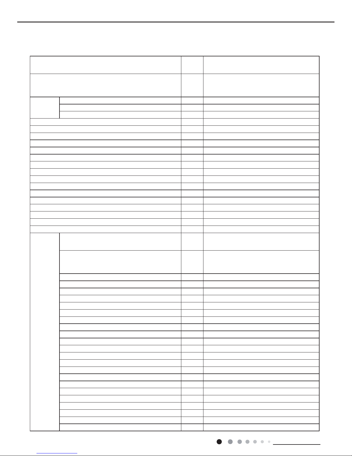
2. Specifi cations
2.1 Specifi cation Sheet
Model
GWH09RB-K3DNA2C, GWH09RB-K3DNA3C
GWH09RB-K3DNA5C, GWH09RB-K3DNA6C
GWH09RB-K3DNA8C, GWH09RB-K3DNA9C
Product Code
CB301001100, CB302000900
CB304000500, CB305000100
CB313000100, CB314000100
CB314000101
Power
Supply
Rated Voltage V~ 220-240
Rated Frequency Hz 50
Phases 1
Power Supply Mode Indoor
Cooling Capacity (Min~Max) W 2600(880~3000)
Heating Capacity (Min~Max) W 2750(760~3500)
Cooling Power Input (Min~Max) W 720(110~1200)
Heating Power Input (Min~Max) W 720(110~1470)
Cooling Power Current A 3.13
Heating Power Current A 3.13
Rated Input W 1550
Rated Current A 7.00
Air Flow Volume(SH/H/M/L/SL) m
3
/h 600/500/400/300/Dehumidifying Volume L/h 0.80
EER W/W /
COP W/W /
SEER W/W 6.40
SCOP W/W 4.00
Application Area m
2
12-18
Indoor Unit
Model of Indoor Unit
GWH09RB-K3DNA2C/I, GWH09RB-K3DNA3C/I
GWH09RB-K3DNA5C/I, GWH09RB-K3DNA6C/I
GWH09RB-K3DNA8C/I, GWH09RB-K3DNA9C/I
Product Code of Indoor Unit
CB301N01100, CB302N00900
CB304N00500, CB305N00100
CB313N00100, CB314N00100
CB314N00101
Fan Type Cross-fl ow
Diameter Length(DXL) mm Φ92X645
Fan Motor Cooling Speed (SH/H/M/L/SL) r/min 1260/1050/900/690/Fan Motor Heating Speed (SH/H/M/L/SL) r/min 1320/1200/1000/910/Output of Fan Motor W 20
Fan Motor RLA A 0.10
Fan Motor Capacitor μF 1.0
Input of Heater W /
Evaporator Form Aluminum Fin-copper Tube
Pipe Diameter mm Φ7
Row-fi n Gap mm 2-1.4
Coil Length (LXDXW) mm 640X24.8X266.7
Swing Motor Model MP24AA
Output of Swing Motor W 2
Fuse A 3.15
Sound Pressure Level (SH/H/M/L/SL) dB (A) 41/34/30/23/Sound Power Level (SH/H/M/L/SL) dB (A) 58/49/44/38/Dimension (WXHXD) mm 845X275X189
Dimension of Carton Box (LXWXH) mm 923X264X356
Dimension of Package (LXWXH) mm 926X267X371
Net Weight kg 10.0
Gross Weight kg 13.0
5
Technical Information
Service Manual
The above data is subject to change without notice. Please refer to the nameplate of the unit.
Outdoor
Unit
O/C3AND3K-BR90HWGtinU roodtuO fo ledoM
00900W203BCtinU roodtuO fo edoC tcudorP
.DTL ,.OC ROSSERPMOC ADNAL IAHUHZ kramedarT/rerutcafunaM rosserpmoC
A091Ez680A-AXQledoM rosserpmoC
PE86 BR / D86 CVFliO rosserpmoC
yratoRepyT rosserpmoC
05.61A .A.R.L
02.4A ALR rosserpmoC
188WtupnI rewoP rosserpmoC
3326-L11TN1rotcetorP daolrevO
evlav noisnapxe nortcelEdohteM gnilttorhT
03~6
-15~43
-15~24
1Cºpmet noitarepO
Cº)gnilooC( pmet tneibmA
Cº)gnitaeH( pmet tneibmA
ebuT reppoc-niF munimulA mroF resnednoC
mm retemaiD epiP
Rows-fin Gap
Φ
7
4.1-2mm
605X83X086mm )WXDXL( htgneL lioC
056/009mprdeepS rotoM naF
Output of Fan Motor W 30
Fan Motor RLA A 0.15
Fan Motor Capacitor μ /F
Air Flow Volume of Outdoor Unit m
3
/h 1600
Fan Type Axial-flow
Fan Diameter mm Φ400
Defrosting Method Automatic Defrosting
Climate Type T1
Isolation I
Moisture Protection IP24
Permissible Excessive Operating Pressure for the
Discharge Side
MPa 4.3
Permissible Excessive Operating Pressure for the
Suction Side
MPa 2.5
Sound Pressure Level (H/M/L) dB (A) 50/-/Sound Power Level (H/M/L) dB (A) 63/-/Dimension (WXHXD) mm 776X540X320
Dimension of Carton Box (LXWXH) mm 848X360X580
Dimension of Package (LXWXH) mm 851X363X595
Net Weight kg 30.0
Gross Weight kg 32.0
Refrigerant R410A
Refrigerant Charge kg 0.90
Connection
Pipe
Length m 5
Gas Additional Charge g/m 20
Outer Diameter Liquid Pipe mm Φ6
Outer Diameter Gas Pipe mm Φ9.52
Max Distance Height m 10
Max Distance Length m 15
Note: The connection pipe applies metric diameter.
6
Technical Information
Service Manual
Model GWH09RB-K3DNA2C, GWH09RB-K3DNA3C
Product Code CB301001102, CB302000901
Power
Supply
Rated Voltage V~ 220-240
Rated Frequency Hz 50
Phases 1
Power Supply Mode Indoor
Cooling Capacity (Min~Max) W 2600(880~3000)
Heating Capacity (Min~Max) W 2750(760~3500)
Cooling Power Input (Min~Max) W 720(110~1200)
Heating Power Input (Min~Max) W 720(110~1470)
Cooling Power Current A 3.13
Heating Power Current A 3.13
Rated Input W 1550
Rated Current A 7.00
Air Flow Volume(SH/H/M/L/SL) m
3
/h 600/500/400/300/-
Dehumidifying Volume L/h 0.80
EER W/W /
COP W/W /
SEER W/W 6.40
SCOP W/W 4.00
Application Area m
2
12-18
Indoor Unit
Model of Indoor Unit GWH09RB-K3DNA2C/I, GWH09RB-K3DNA3C/I
Product Code of Indoor Unit CB301001102, CB302000901
Fan Type Cross-fl ow
Diameter Length(DXL) mm Φ92X645
Fan Motor Cooling Speed (SH/H/M/L/SL) r/min 1260/1050/900/690/-
Fan Motor Heating Speed (SH/H/M/L/SL) r/min 1320/1200/1000/910/-
Output of Fan Motor W 20
Fan Motor RLA A 0.10
Fan Motor Capacitor μF 1.0
Input of Heater W /
Evaporator Form Aluminum Fin-copper Tube
Pipe Diameter mm Φ7
Row-fi n Gap mm 2-1.4
Coil Length (LXDXW) mm 640X24.8X266.7
Swing Motor Model MP24AA
Output of Swing Motor W 2
Fuse A 3.15
Sound Pressure Level (SH/H/M/L/SL) dB (A) 41/34/30/23/-
Sound Power Level (SH/H/M/L/SL) dB (A) 58/49/44/38/-
Dimension (WXHXD) mm 845X275X189
Dimension of Carton Box (LXWXH) mm 923X264X356
Dimension of Package (LXWXH) mm 926X267X371
Net Weight kg 10.0
Gross Weight kg 13.0
7
Technical Information
Service Manual
The above data is subject to change without notice. Please refer to the nameplate of the unit.
Outdoor
Unit
O/C3AND3K-BR90HWGtinU roodtuO fo ledoM
10900W203BCtinU roodtuO fo edoC tcudorP
.DTL ,.OC ROSSERPMOC ADNAL IAHUHZ kramedarT/rerutcafunaM rosserpmoC
A091Ez680A-AXQledoM rosserpmoC
PE86 BR / D86 CVFliO rosserpmoC
yratoRepyT rosserpmoC
05.61A .A.R.L
02.4A ALR rosserpmoC
188WtupnI rewoP rosserpmoC
3326-L11TN1rotcetorP daolrevO
evlav noisnapxe nortcelEdohteM gnilttorhT
03~61Cºpmet noitarepO
Cº)gnilooC( pmet tneibmA
Cº)gnitaeH( pmet tneibmA
ebuT reppoc-niF munimulA mroF resnednoC
mm retemaiD epiP Φ
7
4.1-2mm
605X83X086mm )WXDXL( htgneL lioC
056/009mprdeepS rotoM naF
03WrotoM naF fo tuptuO
51.0A ALR rotoM naF
Fan Motor Capacitor μ /F
mtinU roodtuO fo emuloV wolF riA
3
/h 1600
Fan Type
Fan Diameter mm Φ400
Defrosting Method Automatic Defrosting
Climate Type T1
Isolation I
Moisture Protection IP24
Permissible Excessive Operating Pressure for the
Discharge Side
MPa 4.3
Permissible Excessive Operating Pressure for the
Suction Side
MPa 2.5
Sound Pressure Level (H/M/L) dB (A) 50/-/-
Sound Power Level (H/M/L) dB (A) 63/-/-
Dimension (WXHXD) mm 776X540X320
Dimension of Carton Box (LXWXH) mm 848X360X580
Dimension of Package (LXWXH) mm 851X363X595
Net Weight kg 30.0
Gross Weight kg 32.0
Refrigerant R410A
Refrigerant Charge kg 0.90
Connection
Pipe
Length m 5
Gas Additional Charge g/m 20
Outer Diameter Liquid Pipe mm Φ6
Outer Diameter Gas Pipe mm Φ9.52
Max Distance Height m 10
Max Distance Length m 15
Note: The connection pipe applies metric diameter.
-15~43
-15~24
Rows-fin Gap
Axial-flow
8
Technical Information
Service Manual
Model
GWH12RB-K3DNA2C, GWH12RB-K3DNA3C
GWH12RB-K3DNA5C, GWH12RB-K3DNA6C
GWH12RB-K3DNA8C, GWH12RB-K3DNA9C
Product Code
CB301001200, CB302001000
CB304000600, CB305000200
CB313000200, CB314000200
CB314000201
Power
Supply
Rated Voltage V~ 220-240
Rated Frequency Hz 50
Phases 1
Power Supply Mode Indoor
Cooling Capacity (Min~Max) W 3500(480~4000)
Heating Capacity (Min~Max) W 3650(650~4280)
Cooling Power Input (Min~Max) W 1100(110~1300)
Heating Power Input (Min~Max) W 1100(110~1580)
Cooling Power Current A 4.78
Heating Power Current A 4.78
Rated Input W 1700
Rated Current A 8.00
Air Flow Volume(SH/H/M/L/SL) m
3
/h 600/500/400/300/Dehumidifying Volume L/h 1.20
EER W/W /
COP W/W /
SEER W/W 6.40
SCOP W/W 3.80
Application Area m
2
16-24
Indoor Unit
Model of Indoor Unit
GWH12RB-K3DNA2C/I, GWH12RB-K3DNA3C/I
GWH12RB-K3DNA5C/I, GWH12RB-K3DNA6C/I
GWH12RB-K3DNA8C/I, GWH12RB-K3DNA9C/I
Product Code of Indoor Unit
CB301N01200, CB302N01000
CB304N00600, CB305N00200
CB313N00200, CB314N00200
CB314N00201
Fan Type Cross-fl ow
Diameter Length(DXL) mm Φ92X645
Fan Motor Cooling Speed (SH/H/M/L/SL) r/min 1290/1070/900/690/Fan Motor Heating Speed (SH/H/M/L/SL) r/min 1280/1050/980/920/Output of Fan Motor W 20
Fan Motor RLA A 0.10
Fan Motor Capacitor μF 1.0
Input of Heater W /
Evaporator Form Aluminum Fin-copper Tube
Pipe Diameter mm Φ7
Row-fi n Gap mm 2-1.4
Coil Length (LXDXW) mm 640X24.8X266.7
Swing Motor Model MP24AA
Output of Swing Motor W 2
Fuse A 3.15
Sound Pressure Level (SH/H/M/L/SL) dB (A) 42/35/32/23/Sound Power Level (SH/H/M/L/SL) dB (A) 58/50/46/38/Dimension (WXHXD) mm 845X275X189
Dimension of Carton Box (LXWXH) mm 923X264X356
Dimension of Package (LXWXH) mm 926X267X371
Net Weight kg 10.0
Gross Weight kg 13.0
9
Technical Information
Service Manual
The above data is subject to change without notice. Please refer to the nameplate of the unit.
Outdoor
Unit
O/C3AND3K-BR21HWGtinU roodtuO fo ledoM
00010W203BCtinU roodtuO fo edoC tcudorP
.DTL ,.OC ROSSERPMOC ADNAL IAHUHZ kramedarT/rerutcafunaM rosserpmoC
A091Ez190A-AXQledoM rosserpmoC
PE86 BR / D86 CVFliO rosserpmoC
yratoRepyT rosserpmoC
05.61A .A.R.L
05.4A ALR rosserpmoC
249WtupnI rewoP rosserpmoC
3326-L11TN1rotcetorP daolrevO
evlav noisnapxe nortcelEdohteM gnilttorhT
03~61Cºpmet noitarepO
Cº)gnilooC( pmet tneibmA
Cº)gnitaeH( pmet tneibmA
ebuT reppoc-niF munimulA mroF resnednoC
mm retemaiD epiP Φ
9.52
4.1-2mm
805X1.83X037mm )WXDXL( htgneL lioC
Fan Motor Speed rpm 900/650
Output of Fan Motor W 30
Fan Motor RLA A 0.15
Fan Motor Capacitor μ /F
Air Flow Volume of Outdoor Unit m
3
/h 1800
Fan Type
Fan Diameter mm Φ400
Defrosting Method Automatic Defrosting
Climate Type T1
Isolation I
Moisture Protection IP24
Permissible Excessive Operating Pressure for the
Discharge Side
MPa 4.3
Permissible Excessive Operating Pressure for the
Suction Side
MPa 2.5
Sound Pressure Level (H/M/L) dB (A) 58/-/Sound Power Level (H/M/L) dB (A) 63/-/Dimension (WXHXD) mm 848X540X320
Dimension of Carton Box (LXWXH) mm 878X360X580
Dimension of Package (LXWXH) mm 881X363X595
Net Weight kg 33.0
Gross Weight kg 35.0
Refrigerant R410A
Refrigerant Charge kg 1.15
Connection
Pipe
Length m 5
Gas Additional Charge g/m 20
Outer Diameter Liquid Pipe mm Φ6
Outer Diameter Gas Pipe mm Φ9.52
Max Distance Height m 10
Max Distance Length m 20
Note: The connection pipe applies metric diameter.
Axial-flow
-15~43
-15~24
Rows-fin Gap

10
Technical Information
Service Manual
Model GWH12RB-K3DNA2C, GWH12RB-K3DNA3C
Product Code CB301001202, CB302001001
Power
Supply
Rated Voltage V~ 220-240
Rated Frequency Hz 50
Phases 1
Power Supply Mode Indoor
Cooling Capacity (Min~Max) W 3500(480~4000)
Heating Capacity (Min~Max) W 3650(650~4280)
Cooling Power Input (Min~Max) W 1100(110~1300)
Heating Power Input (Min~Max) W 1100(110~1580)
Cooling Power Current A 4.78
Heating Power Current A 4.78
Rated Input W 1700
Rated Current A 8.00
Air Flow Volume(SH/H/M/L/SL) m
3
/h 600/500/400/300/-
Dehumidifying Volume L/h 1.20
EER W/W /
COP W/W /
SEER W/W 6.40
SCOP W/W 3.80
Application Area m
2
16-24
Indoor Unit
Model of Indoor Unit GWH12RB-K3DNA2C/I, GWH12RB-K3DNA3C/I
Product Code of Indoor Unit CB301N01201, CB302N01001
Fan Type Cross-fl ow
Diameter Length(DXL) mm Φ92X645
Fan Motor Cooling Speed (SH/H/M/L/SL) r/min 1290/1070/900/690/-
Fan Motor Heating Speed (SH/H/M/L/SL) r/min 1280/1050/980/920/-
Output of Fan Motor W 20
Fan Motor RLA A 0.10
Fan Motor Capacitor μF 1.0
Input of Heater W /
Evaporator Form Aluminum Fin-copper Tube
Pipe Diameter mm Φ7
Row-fi n Gap mm 2-1.4
Coil Length (LXDXW) mm 640X24.8X266.7
Swing Motor Model MP24AA
Output of Swing Motor W 2
Fuse A 3.15
Sound Pressure Level (SH/H/M/L/SL) dB (A) 42/35/32/23/-
Sound Power Level (SH/H/M/L/SL) dB (A) 58/50/46/38/-
Dimension (WXHXD) mm 845X275X189
Dimension of Carton Box (LXWXH) mm 923X264X356
Dimension of Package (LXWXH) mm 926X267X371
Net Weight kg 10.0
Gross Weight kg 13.0
11
Technical Information
Service Manual
The above data is subject to change without notice. Please refer to the nameplate of the unit.
Outdoor
Unit
O/C3AND3K-BR21HWGtinU roodtuO fo ledoM
10010W203BCtinU roodtuO fo edoC tcudorP
.DTL ,.OC ROSSERPMOC ADNAL IAHUHZ kramedarT/rerutcafunaM rosserpmoC
A091Ez190A-AXQledoM rosserpmoC
PE86 BR / D86 CVFliO rosserpmoC
yratoRepyT rosserpmoC
05.61A .A.R.L
05.4A ALR rosserpmoC
249WtupnI rewoP rosserpmoC
3326-L11TN1rotcetorP daolrevO
evlav noisnapxe nortcelEdohteM gnilttorhT
03~61Cºpmet noitarepO
Cº)gnilooC( pmet tneibmA
Cº)gnitaeH( pmet tneibmA
ebuT reppoc-niF munimulA mroF resnednoC
mm retemaiD epiP Φ
9.52
4.1-2mm
805X1.83X037mm )WXDXL( htgneL lioC
056/009mprdeepS rotoM naF
03WrotoM naF fo tuptuO
51.0A ALR rotoM naF
Fan Motor Capacitor μ /F
mtinU roodtuO fo emuloV wolF riA
3
/h 1800
Fan Type
Fan Diameter mm Φ400
Defrosting Method Automatic Defrosting
Climate Type T1
Isolation I
Moisture Protection IP24
Permissible Excessive Operating Pressure for the
Discharge Side
MPa 4.3
Permissible Excessive Operating Pressure for the
Suction Side
MPa 2.5
Sound Pressure Level (H/M/L) dB (A) 58/-/-
Sound Power Level (H/M/L) dB (A) 63/-/-
Dimension (WXHXD) mm 848X540X320
Dimension of Carton Box (LXWXH) mm 878X360X580
Dimension of Package (LXWXH) mm 881X363X595
Net Weight kg 33.0
Gross Weight kg 35.0
Refrigerant R410A
Refrigerant Charge kg 1.15
Connection
Pipe
Length m 5
Gas Additional Charge g/m 20
Outer Diameter Liquid Pipe mm Φ6
Outer Diameter Gas Pipe mm Φ9.52
Max Distance Height m 10
Max Distance Length m 20
Note: The connection pipe applies metric diameter.
-15~43
-15~24
Rows-fin Gap
Axial-flow
12
Technical Information
Service Manual
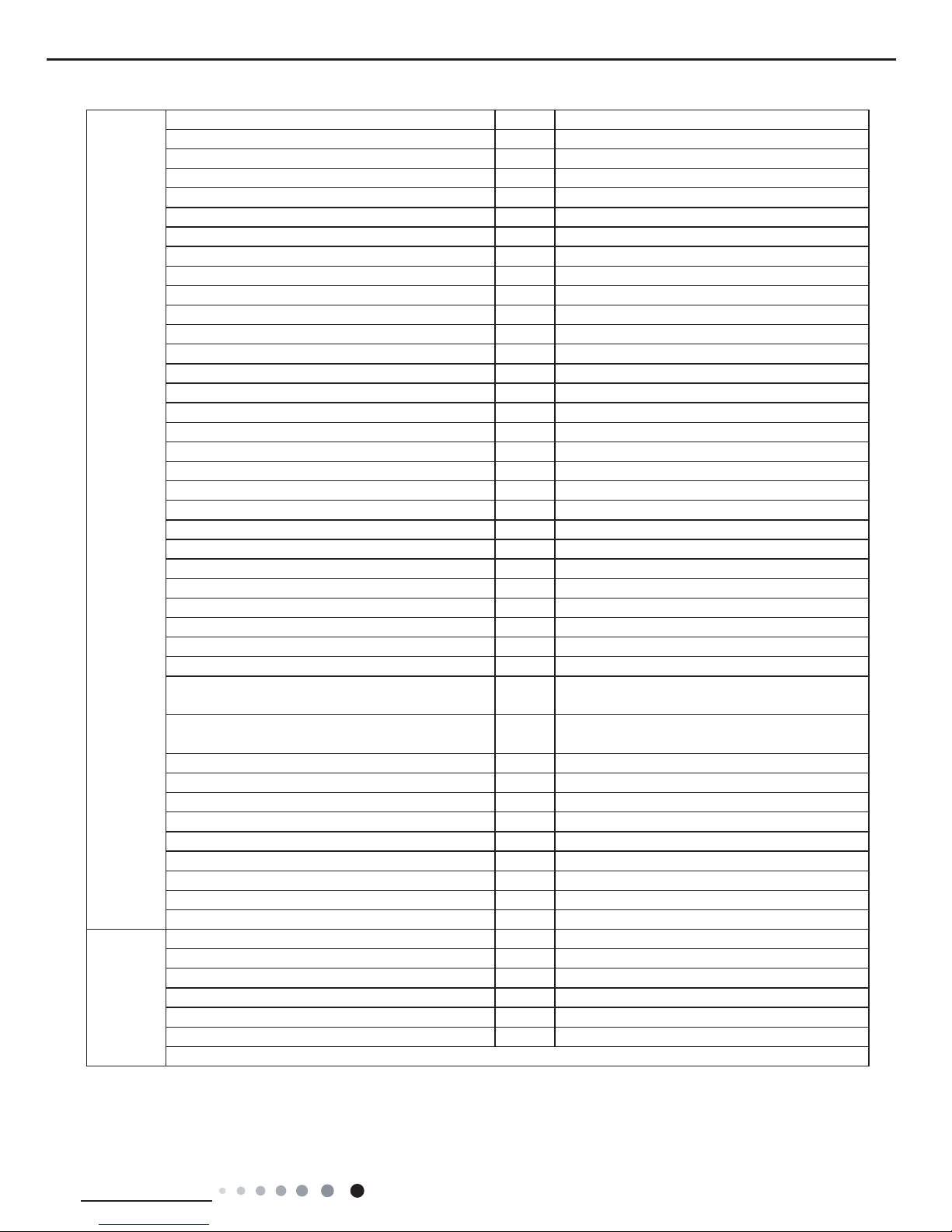
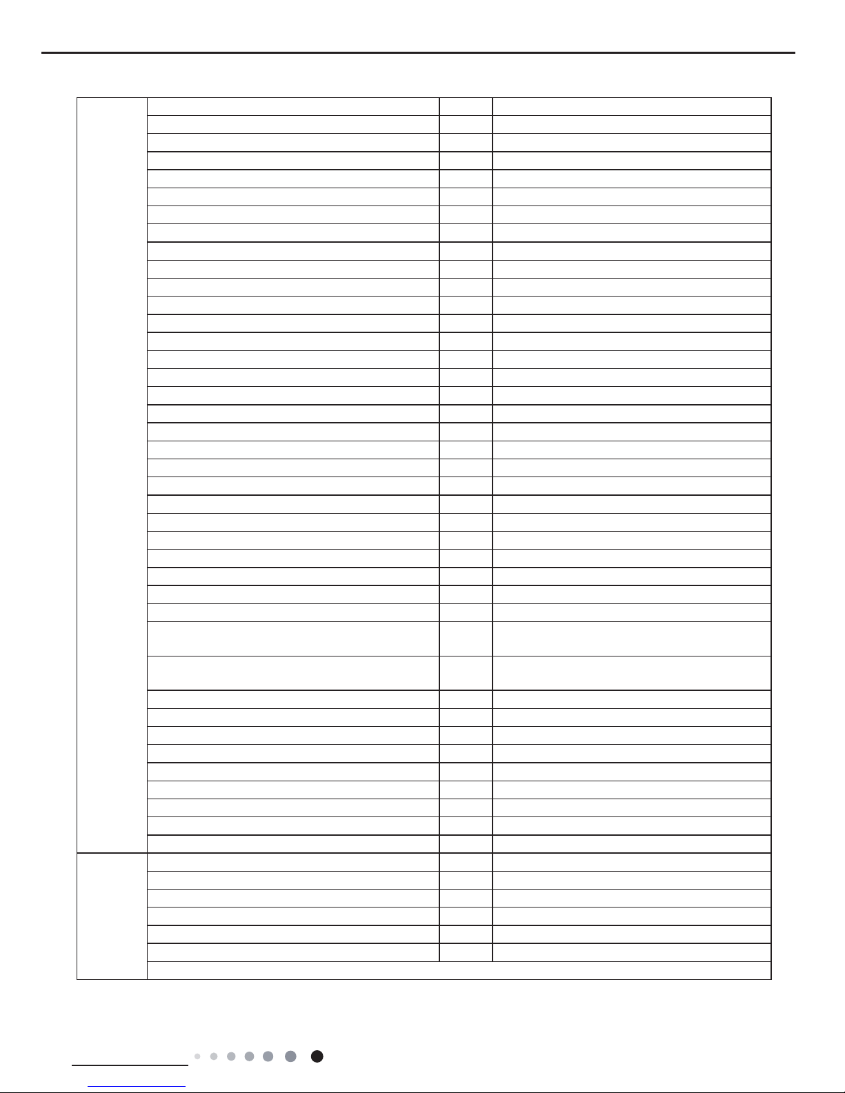
2.2 Operation Characteristic Curve
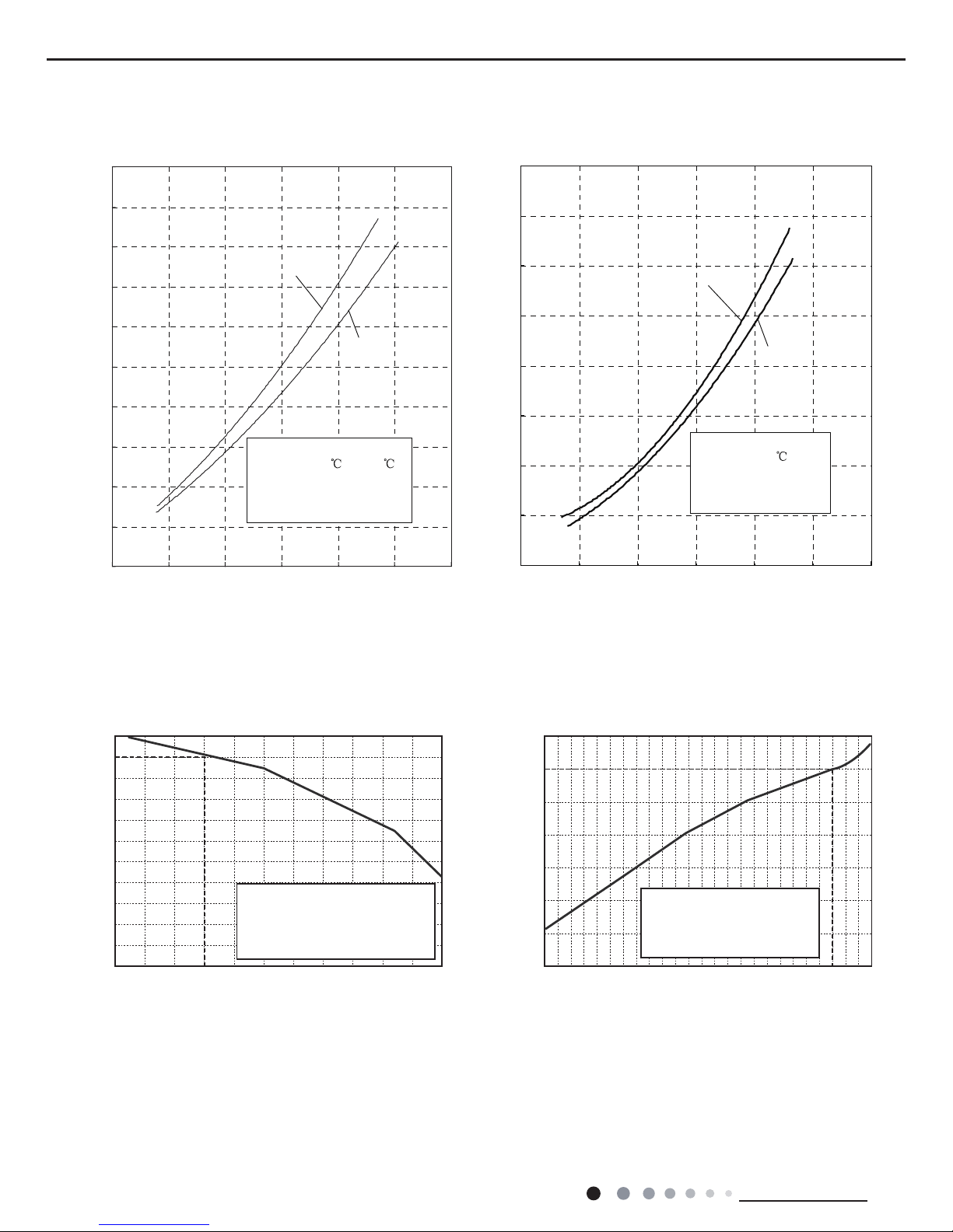
2.3 Capacity Variation Ratio According to Temperature
0
1
2
3
4
5
6
7
8
9
10
0 20 40 60 80 100 120
Condition
Indoor:DB 27
WB19
Indoor air flow: Turbo
Pipe length:5m
Voltage:230V
Compressor Speed(rps)
0
1
2
3
4
5
6
7
8
0 20 40 60 80 100 120
Condition
Indoor:DB 20
Indoor air flow:Turbo
Pipe length:5m
Voltage:230V
Compressor Speed(rps)
Cooling
Heating
Current(A)
Current(A)
09K
12K
09K
12K
Cooling Heating
28 30 32 34 36 38 40 42
48
–15 –10 –5
43 44 46
100
105
95
90
85
80
75
70
65
60
55
50
110
100
90
80
70
60
50
40
0 5 7 1
0
Conditions
Indoor:DB27°C/WB19°C
Indoor air flow:Super High
Pipe length: 5m
Conditions
Indoor:DB20°C/WB15°C
Indoor air flow:Super High
Pipe length: 5m
Outdoor temp.(°C) Outdoor temp.(°C)
Capacity ratio (%)
Capacity ratio (%)
Cooling
Heating
13
Technical Information
Service Manual
2.4 Cooling and Heating Data Sheet in Rated Frequency
Rated cooling
condition(℃) (DB/WB)
Model
Pressure of gas pipe
connecting indoor and
outdoor unit
Inlet and outlet pipe temperature
of heat exchanger
Fan speed of
indoor unit
Fan speed of
outdoor unit
Compressor
revolution
(Hz)
Indoor Outdoor P (MPa) T1 (℃) T2 (℃)
27/19 35/24
09K
0.85~1.0
in:8~11
out:11~14
in:50~80
out:37~43
Turbo Suprt High
49
12K 68
Rated cooling
condition(℃) (DB/WB)
Model
Pressure of gas pipe
connecting indoor and
outdoor unit
Inlet and outlet pipe
temperature of heat exchanger
Fan speed of
indoor unit
Fan speed of
outdoor unit
Compressor
revolution
(Hz)
Indoor Outdoor P (MPa) T1 (°C) T2 (°C)
20/- 7/6
09K
2.5~3.0
in:50~80
out:37~43
in:1~3
out:2~5
Turbo Suprt High
54
12K 71
Instruction:
T1: Inlet and outlet pipe temperature of evaporator
T2: Inlet and outlet pipe temperature of condenser
P: Pressure at the side of big valve
Connection pipe length: 5 m.
Cooling:
Heating:
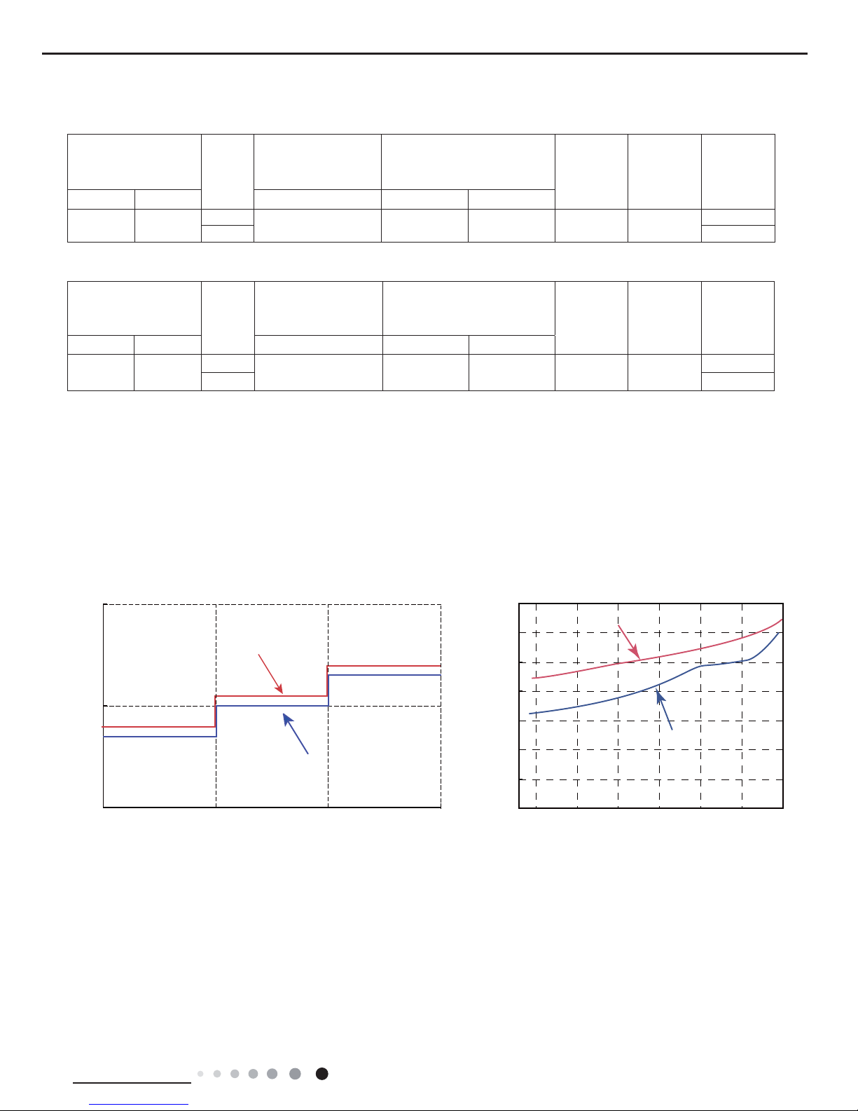
2.5 Noise Curve
45
35
25
Indoor side noise when blowing
Indoor fan motor rotating speed
Low Middle High
12K
40
42
44
46
48
50
52
54
20 4030 50 60 70 80
Compressor frequency(Hz)
Noise dB(A)
Noise dB(A)
Heating
Cooling
09K
14
Technical Information
Service Manual
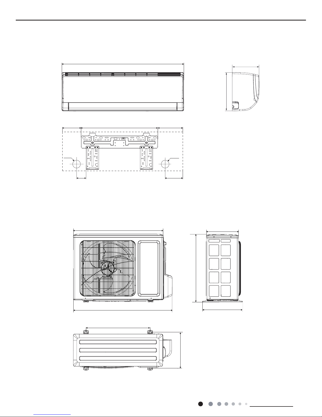
3. Outline Dimension Diagram
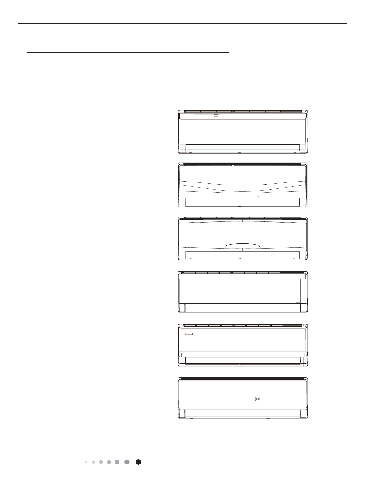
3.1 Indoor Unit
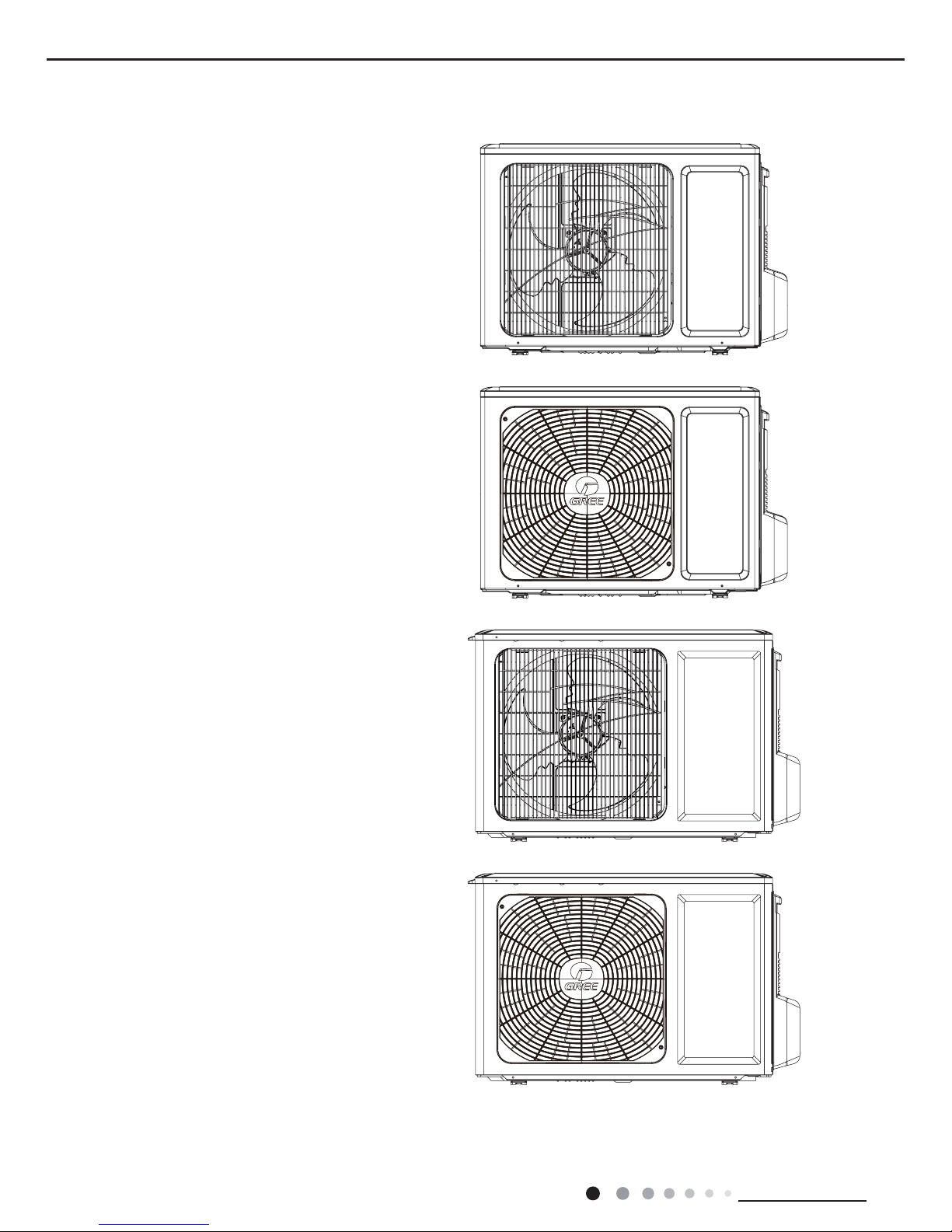
3.2 Outdoor Unit
69 124
Φ55
Φ55
845
130
542
173
Unit: mm
257
320
776
540
712
510
286
GWH09RB-K3DNA3C/O(CB302W00900)
275
180
15
Technical Information
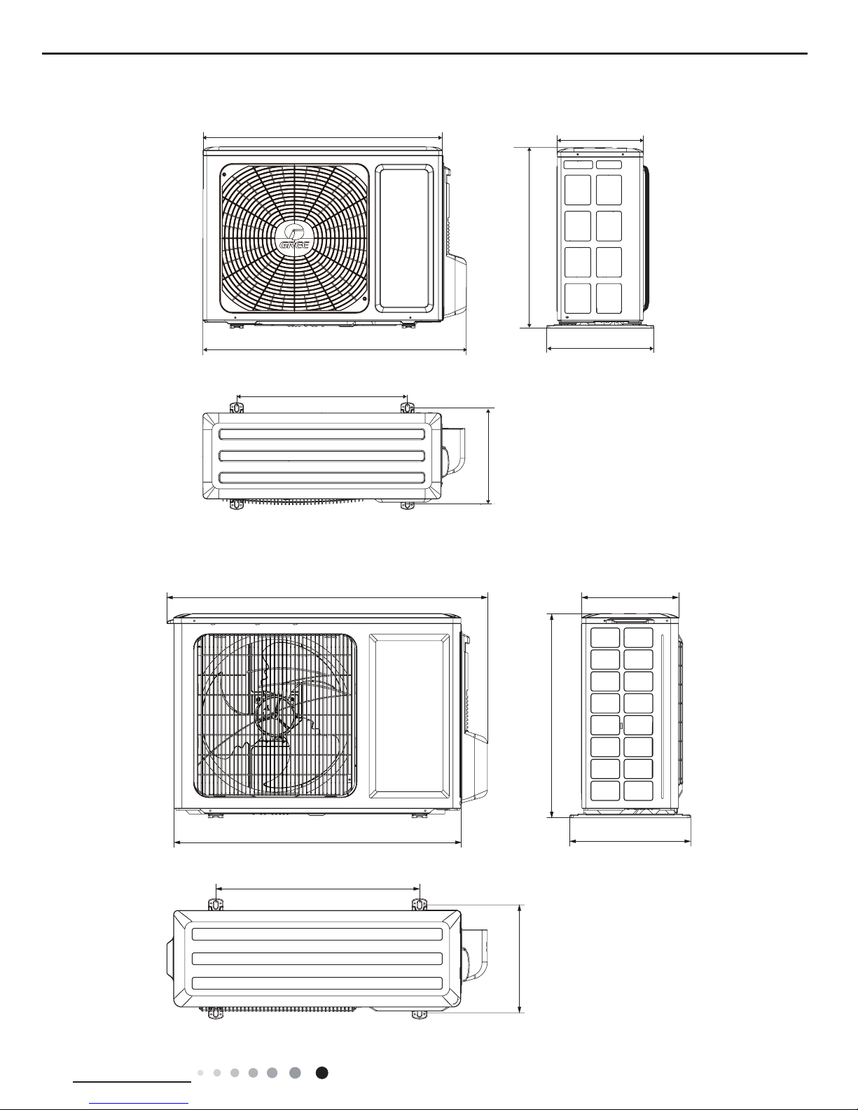
Service Manual
848
763
540
257
045
320
682
GWH12RB-K3DNA3C/O(CB302W01000)
GWH09RB-K3DNA3C/O(CB302W00901)
257
320
776
540
712
510
286
Unit: mm
16
Technical Information
Service Manual
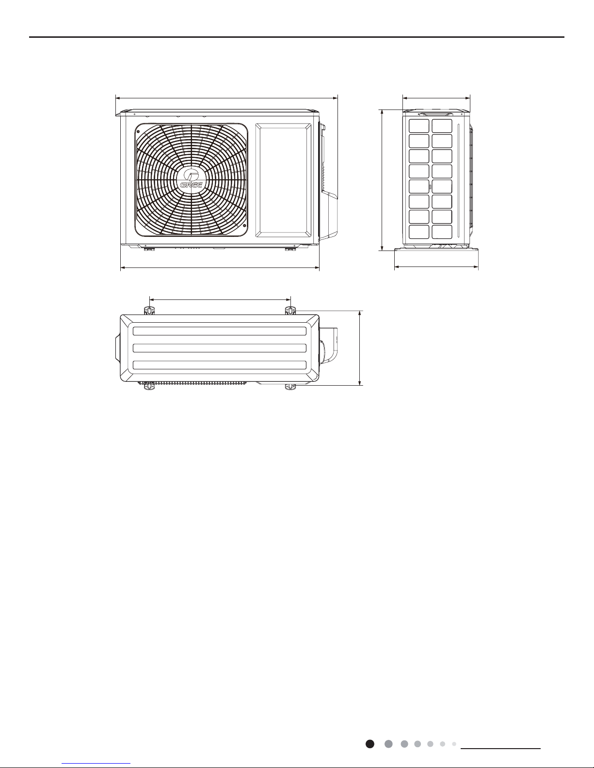
GWH12RB-K3DNA3C/O(CB302W01001)
848
763
540
257
045
320
682
Unit: mm
17
Technical Information
Service Manual
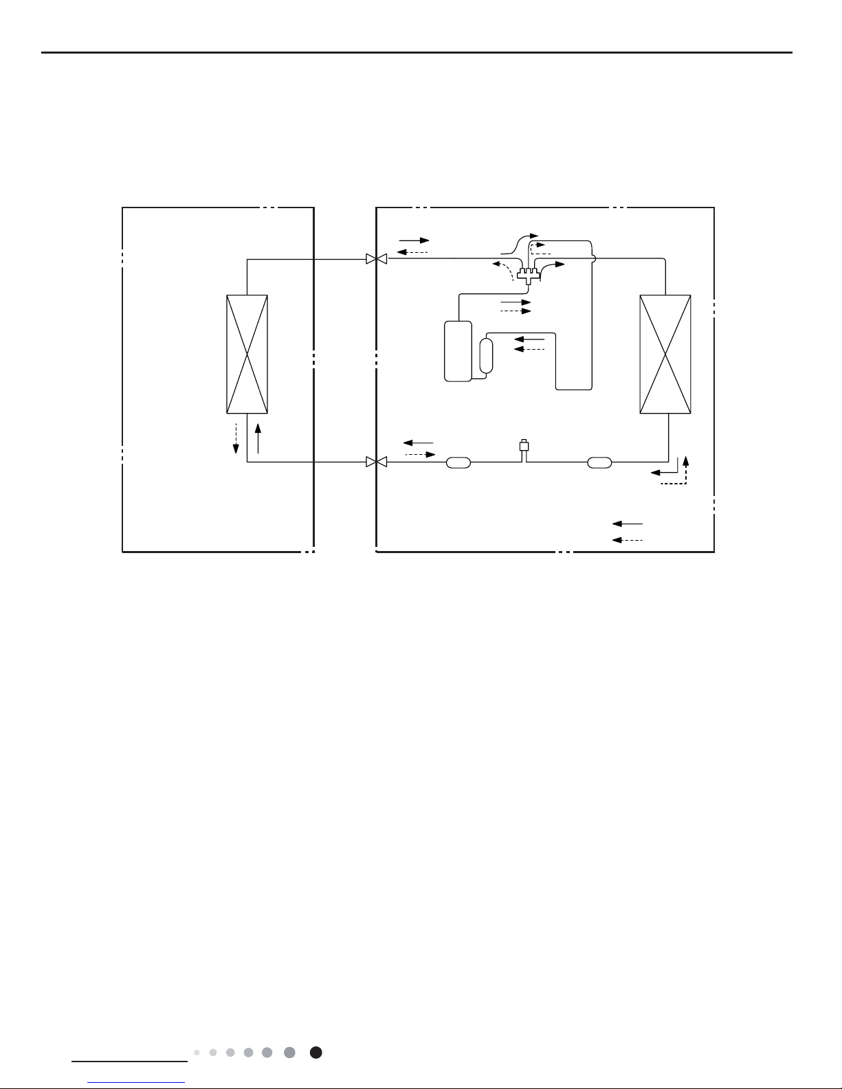
4. Refrigerant System Diagram
Cooling and Heating Model
Connection pipe
specifi cation:
Liquid : 1/4" (6mm)
Gas : 3/8" (9.52mm)
Indoor unit
Outdoor unit
COOLING
HEATING
Accumlator
4-Way valve
Discharge
Suction
Heat
exchanger
(evaporator)
Heat
exchanger
(condenser)
Valve
Valve
Liquid pipe
side
Gas pipe
side
Strainer
Strainer
Electron
expansion
valve
18
Technical Information
Service Manual
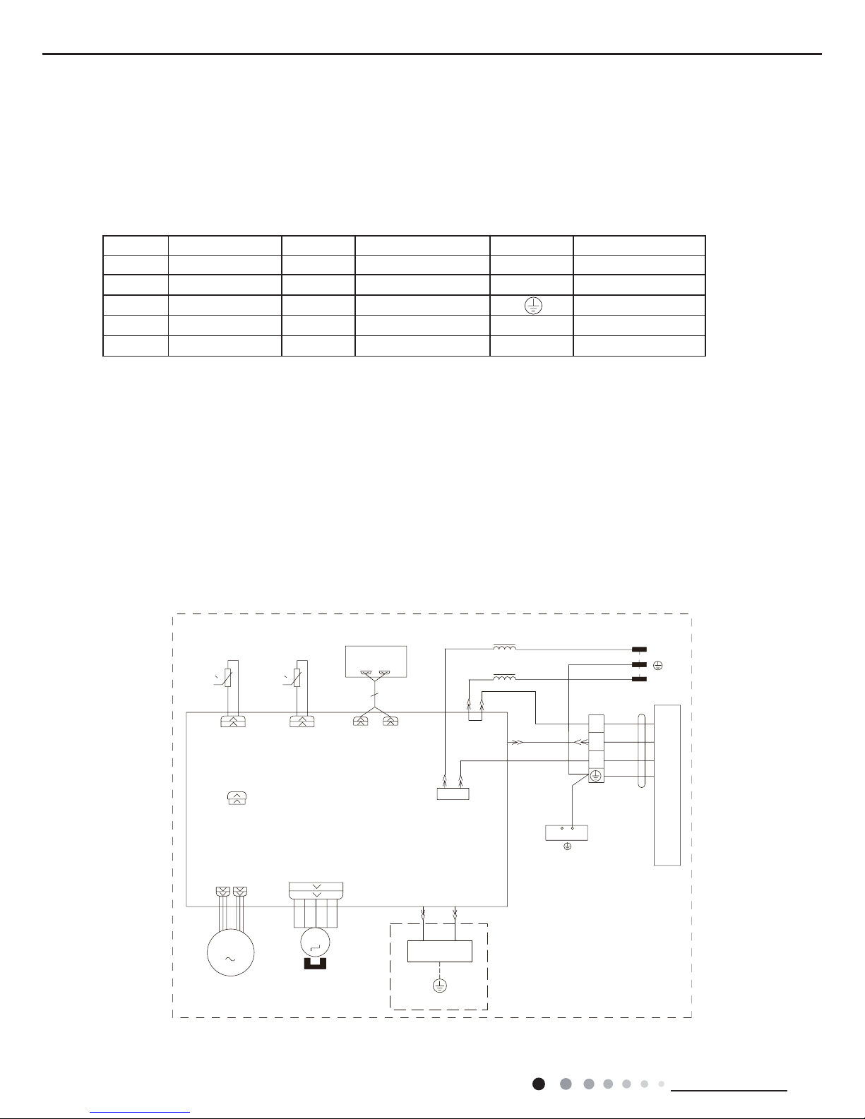
5. Electrical Part
5.1 Wiring Diagram
● Indoor Unit
●Instruction
Symbol Symbol Color Symbol Symbol Color Symbol Name
WH White GN Green CAP Jumper cap
YE Yellow BN Brown COMP Compressor
RD Red BU Blue Grounding wire
YEGN Yellow/Green BK Black / /
VT Violet OG Orange / /
Note: Jumper cap is used to determine fan speed and the swing angle of horizontal lover for this model.
L-OUT
L1
L1
00
RT1 RT2
M
JUMP
CAP
TEM.SENSOR
ROOM
TUBE
TEM.SENSOR
FAN MOTOR
SWING MOTOR(U.D)
AP2
SWING-UD
K4
TUBEROOM
AC-L
PG
PGF
DISP-1 DISP-2
CN2
CN1
AP1
DISPLAY
GENERATOR
COOL PLASMA
M
PE
XT1
W1 BU
W3 BN
N(1)
OUTDOOR UNIT
2
3
COM-OUT
W4 YEGN
N
W2 BK
BU
YEGN
BN
L
N
POWER
RD BU
YEGN
HEALTH-NHEALTH-L
PE
BU
BK
BN
YEGN
EVAPORATOR
GWH09RB-K3DNA2C/I(CB301N01100), GWH09RB-K3DNA2C/I(CB301N01101), GWH09RB-K3DNA3C/I(CB302N00900)
GWH09RB-K3DNA5C/I(CB304N00500), GWH09RB-K3DNA8C/I(CB313N00100), GWH12RB-K3DNA2C/I(CB301N01200)
GWH12RB-K3DNA2C/I(CB301N01201), GWH12RB-K3DNA3C/I(CB302N01000), GWH12RB-K3DNA5C/I(CB304N00600)
GWH12RB-K3DNA8C/I(CB313N00200), GWH09RB-K3DNA6C/I(CB305N00100), GWH12RB-K3DNA6C/I(CB305N00200)
GWH09RB-K3DNA9C/I(CB314N00100), GWH09RB-K3DNA9C/I(CB314N00101), GWH12RB-K3DNA9C/I(CB314N00200)
GWH12RB-K3DNA9C/I(CB314N00201)
19
Technical Information
Service Manual
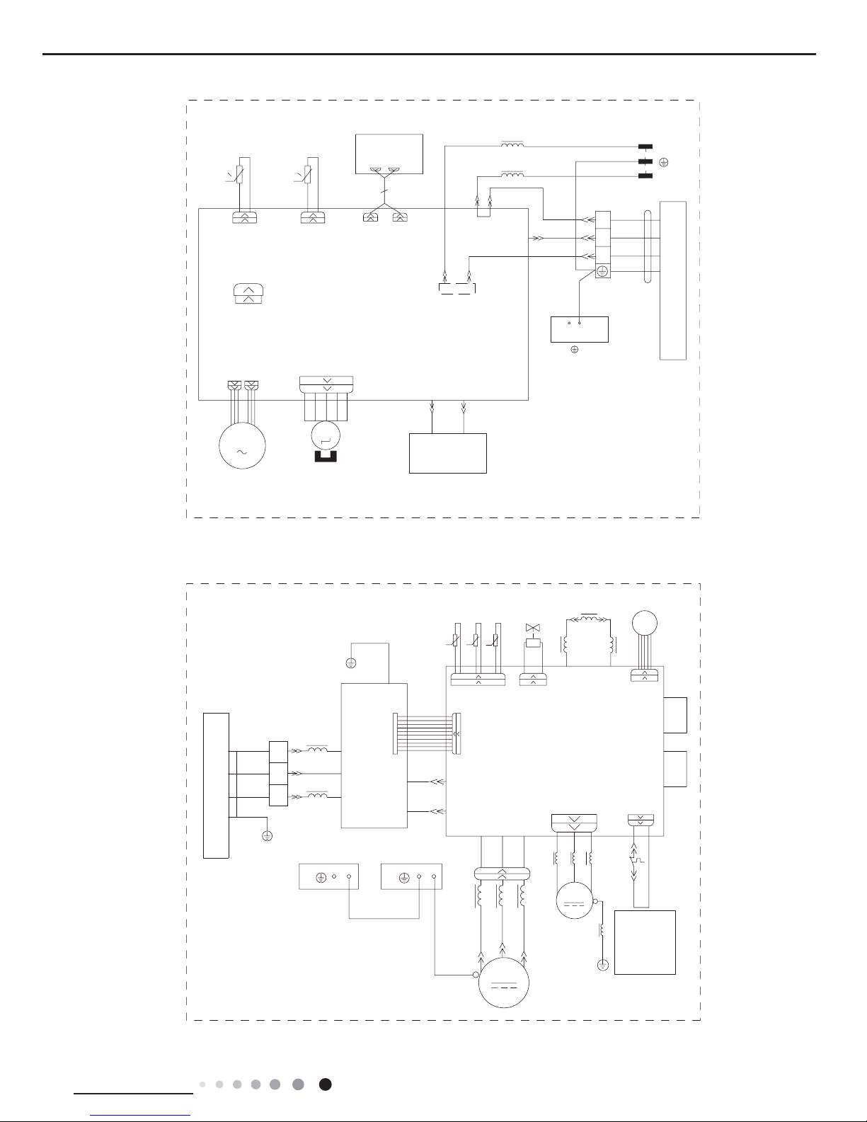
● Outdoor Unit
GWH09RB-K3DNA3C/I(CB302N00901), GWH12RB-K3DNA3C/I(CB302N01001)
0
0
RT1
RT2
M
TUBEROOM
M
PG
PGF
L-OUT
L1
PE
XT1
W1 BU
W3 BN
N(1)
OUTDOOR UNIT
2
3
COM-OUT
W4 YEGN
N
W2 BK
EVAPORATOR
BU
YEGN
BN
L
N
POWER
DISP-1 DISP-2
RD
BU
HEALTH-NHEALTH-L
BU
BK
BN
YEGN
L1
AC-L
K4
SWING-UD
JUMP
CAP
AP2
DISPLAY
AP1
CN1
CN2
TUBE
TEM.SENSORTEM.SENSOR
ROOM
FAN
MOTOR
SWING
MOTOR(U.D)
COOL PLASMA
GENERATOR
N(1)
XT
3
2
BN
N
AC-L
PE
U
V
W
TUBE
TEM.SENSOR
θ
RT1
RT2
RT3
CN2 4V
N1
AC-L1
L
FAN
OFAN
COMP
COMP
AC-N1
PE
M
PE PE
SHEET
ELECTRIC BOX
4YV
AC-N2
AP1
AP2
AC-L
AC-N
W3
W5
W9
W10
W11
W12
W13
W14 W15
W16
W17 W18
W19
W20
L1
L2
E
W21
AC-L3
AC-L2
LX1-2
LX1-1
OVC-COMP
COM-OUT
L1
PE
PE
CN1
CN3
W7
BK
W2
W1
BU
BN
BK
BU
YEGN
YEGN
YEGN
YEGN
YEGN
BN
BN
BN
BU
BU
BU
BU
BU
RD
RD
YE
YE
TEM.SENSOR
OUTROOM
EXHAUST
TEM.SENSOR
T
I
N
U
R
O
O
D
N
I
W6
L3 L3
L2 L2
W22
SAT
RD
W
V
U
NOTE:
Motor ground
only applies
to the iron
shell motor.
EKV
CN1
L4 L4 L4
L4
MID.ISOLATION
θθ
These circuit diagrams are subject to change without notice, please refer to the one supplied with the unit.
20
Technical Information
Service Manual
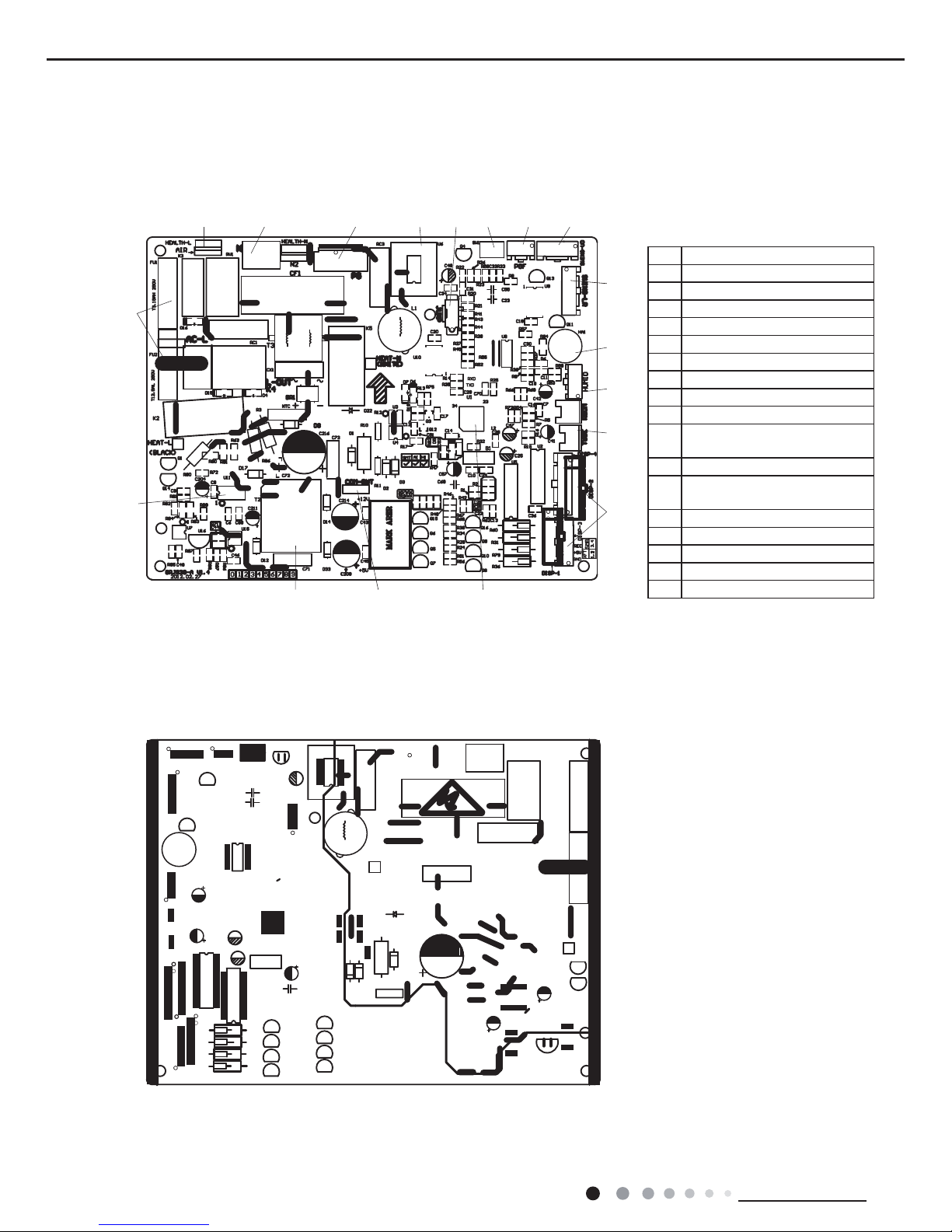
5.2 PCB Printed Diagram
Indoor Unit
●
Top view
●
Bottom view
1
2
435687910
11
12
13
14
15
161718
1 Power of switch
2 Protective tube
3 Live wire of health function
4 Port of neutral wire
5 Port of indoor fan
6 Solid-state relay
7 Jumper Cap
8 Auto button
9 Feedback of indoor fan
10 Port of motor for vertical swing
11
Port of motor for horizontal
swing
12 Buzzer
13
Port of indoor ambient temp
sensor
14 Port of indoor pipe temp sensor
15 Port of display
16 Main chip
17 Communication port
18 High-frequency transformer
21
Technical Information
Service Manual
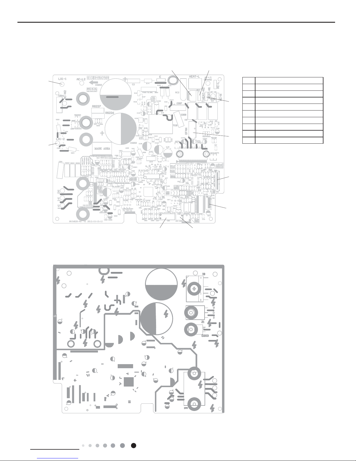
Outdoor Unit
●
Top view
●
Bottom view
1
2
34
5
6
7
8
9
10
1 inductance pin2
2 inductance pin1
3 four-wayvalve
4 compressor electricheater
5 chassis electric heater
6 fan neilsbed
7 10-core communication cable
8 electric expansion valve
9 overload protection
10 temp. sensor
22
Technical Information
Service Manual
6. Function and Control
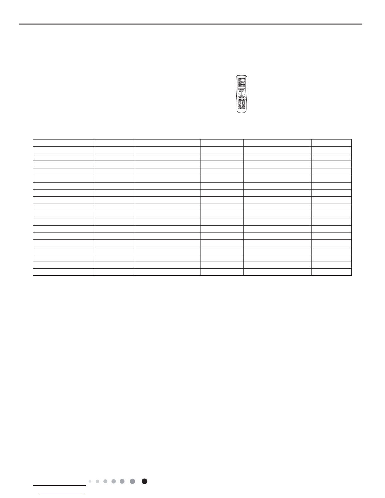
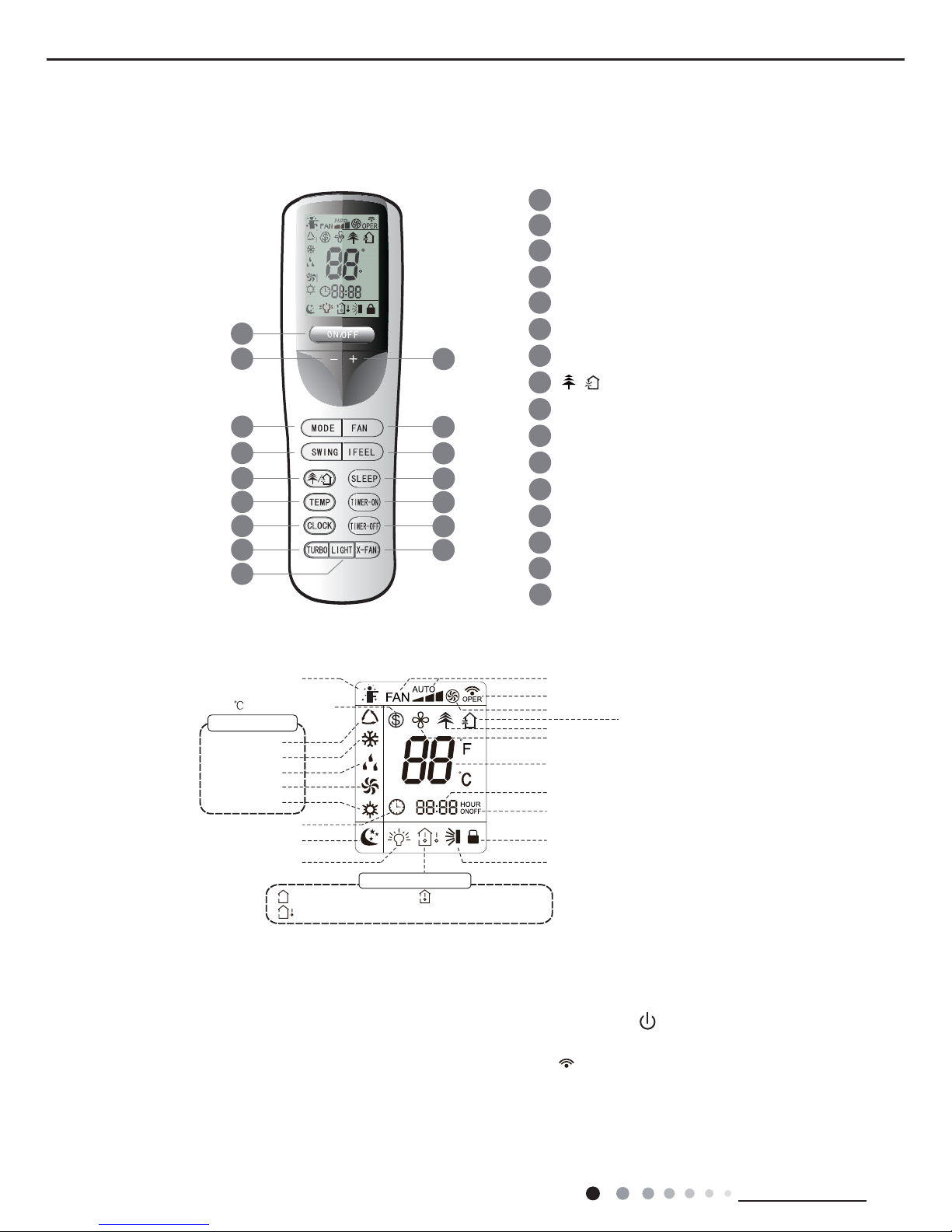
6.1 Remote Controller Introduction
Buttons on Remote Controller
Introduction
for Icons on Display Screen
1
1
2
5
4
6
7
8
11
12
13
9
14
15
ON/OFF button
- button
3
SWING button
FAN button
MODE button
I FEEL button
CLOCK button
10
TIMER-ON button
TIMER-OFF button
TURBO button
LIGHT button
16
X-FAN
button
SLEEP button
TEMP button
button
/
+ button
/
F
C
HOUR
ONOFF
2
3
4
5
6
7
8
9
10
11
12
13
14
16
15
Send signal
Turbo mode
8
heating function
Set temperature
Set time
TIMER ON /
TIMER OFF
Child lock
Up & down swing
Set fan speed
ventilation operation
Light
Temp. display type
:Set temp.
:Outdoor ambient temp.
:Indoor ambient temp.
Sleep mode
Clock
Heat mode
Fan mode
Dry mode
Cool mode
Auto mode
Operation mode
I feel
X-fan mode
health function
Note:
◆
After putting through the power, the air conditioner will give out a sound. Operation indictor "
" is ON (red indicator). After that, you
can operate the air conditioner by using remote controller.
◆
Under on status, pressing the button on the remote controller, the signal icon "
"on the display of remote controller will blink once
and the air conditioner will give out a “de” sound, which means the signal has been sent to the air conditioner.
◆
Under off status, set temperature and clock icon will be displayed on the display of remote controller (If timer on, timer off and light
functions are set, the corresponding icons will be displayed on the display of remote controller at the same time); Under on status, the
display will show the corresponding set function icons.
Introduction for Buttons on Remote Controller
23
Technical Information
Service Manual
1. ON/OFF Button
Press this button to turn on the unit. Press this button again to turn off the unit.
2. - Button
Press this button to decrease set temperature. Holding it down above 2 seconds rapidly decreases set temperature. In AUTO mode,
set temperature is not adjustable.
3. + Button
Press this button to increase set temperature. Holding it down above 2 seconds rapidly increases set temperature. In AUTO mode, set
temperature is not adjustable.
4. MODE Button
Each time you press this button, a mode is selected in a sequence that goes from AUTO, COOL, DRY, FAN, and HEAT*, as the
following:
A
UTO COOL DRY FAN HEAT*
▲
▲
▲
▲
*Note:Only for models with heating function.
After energization, AUTO mode is defaulted. In AUTO mode, the set temperature will not be displayed on the LCD, and the unit will
automatically select the suitable operation mode in accordance with the room temperature to make indoor room comfortable.
(As for cooling only unit, it won’t have any action when it receives the signal of heating operation.)
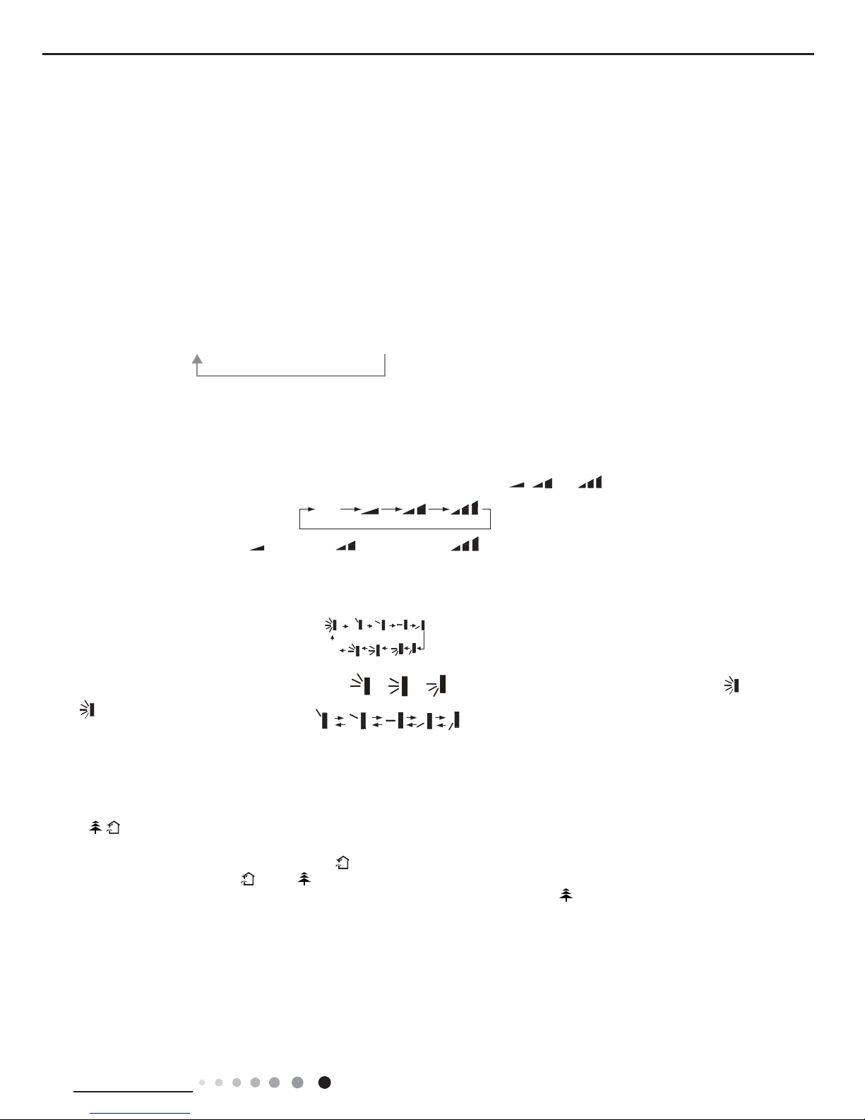
5. FAN Button
This button is used for setting Fan Speed in the sequence that goes from AUTO, , to , then back to Auto.
6. SWING Button
Press this button to set up &down swing angle, which circularly changes as below:
This remote controller is universal. If any command , or is sent out, the unit will carry out the command as .
indicates the guide louver swings as:
7. I FEEL Button
Press this button to turn on I FEEL function. The unit automatically adjust temperature according to the sensed temperature. Press this
button again to cancel I FEEL function.
8. / Button
Press this button to achieve the on and off of healthy and scavenging functions in operation status. Press this button for the fi rst
time to start scavenging function; LCD displays "
". Press the button for the second time to start healthy and scavenging functions
simultaneously; LCD displays "
" and " ". Press this button for the third time to quit healthy and scavenging functions
simultaneously. Press the button for the fourth time to start healthy function; LCD display "
". Press this button again to repeat the
operation above. (This function is applicable to partial of models)
9. SLEEP Button
Press this button to go into the SLEEP operation mode. Press it again to cancel this function. This function is available in COOL, HEAT
(Only for models with heating function) mode to maintain the most comfortable temperature for you.
10. TEMP Button
Press this button, could select displaying the indoor setting temperature or indoor ambient temperature. When the indoor unit fi rstly
Aut o
Low speed
Medium speed
High speed
OFF
24
Technical Information
Service Manual
power on it will display the setting temperature,if the temperature's displaying status is changed from other status to " ", displays the
ambient temperature, 3s later or within 3s, it receives other remote control signal that will return to display the setting temperature. if the
users haven't set up the temperature displaying status, that will display the setting temperature.(This function is applicable to partial of
models)
11. TIMER-ON Button
Press this button to initiate the auto-ON timer. To cancel the auto-timer program, simply press this button again.
After press of this button,
disappears and "ON" blinks. 00:00 is displayed for ON time setting. Within 5 seconds, press + or - button
to adjust the time value. Every press of either button changes the time setting by 1 minute. Holding down either button rapidly changes
the time setting by 1 minute and then 10 minutes. Within 5 Seconds after setting,press TIMER ON button to confi rm.
12. CLOCK Button
Press CLOCK button, blinking. Within 5 seconds, pressing + or - button adjusts the present time. Holding down either button above
2 seconds increases or decreases the time by 1 minute every 0.5 second and then by 10 minutes every 0.5 second. During blinking
after setting, press CLOCK button again to confi rm the setting, and
then will be constantly displayed.
13. TIMER-OFF Button
Press this button to initiate the auto-off timer. To cancel the auto-timer program, simply press the button again. TIMER OFF setting is
the same as TIMER ON.
14. TURBO Button
Press this button to activate / deactivate the Turbo function which enables the unit to reach the preset temperature in the shortest time.
In COOL mode, the unit will blow strong cooling air at super high fan speed. In HEAT mode, the unit will blow strong heating air at super
high fan speed.
15. LIGHT Button
Press LIGHT button to turn on the display's light and press this button again to turn off the display's light. If the light is turned on, is
displayed. If the light is turned off,
disappears.
16. X-FAN Button
Pressing X-FAN button in COOL or DRY mode, the iconis displayed and the indoor fan will continue operation for 2 minutes in order
to dry the indoor unit even though you have turned off the unit.After energization, X-FAN OFF is defaulted. X-FAN is not available in
AUTO, FAN or HEAT mode.
Combination of "+" and "-" buttons: About lock
Press "+" and "-" buttons simultaneously to lock or unlock the keypad. If the remote controller is locked,is displayed
. In this case,
pressing any button,
blinks three times.
Combination of "MODE" and "-" buttons:About switch between Fahrenheit and centigrade
At unit OFF, press "MODE" and "-" buttons simultaneously to switch between °C and °F.
Combination of "TEMP" and "CLOCK" buttons:About Energy-saving Function
Press "TEMP" and "CLOCK" simultaneously in COOL mode to start energy-saving function.Nixie tube on the remote controller displays
"SE". Repeat the operation to quit the function.
Combination of "TEMP" and "CLOCK" buttons:About 8°C Heating Function
Press "TEMP" and "CLOCK" simultaneously in HEAT mode to start 8°C Heating Function Nixie tube on the remote controller displays
" " and a selected temperature of "8°C".(46°F if Fahrenheit is adopted). Repeat the operation to quit the function.
About Back-lighting Function
The unit lights for 4s when energizing for the fi rst time, and 3s for later press.
About HEALTH Function (COLD PLASMA)
Turn on the unit, start up the fan (Breezing and X-FAN are excluded) and press HEATLTH button on remote controller to start health
function (If there is not HEALTH button on remote controller, the unit defaults health function ON.)
Operation guide
1. After putting through the power, press "ON/OFF" button on remote controller to turn on the air conditioner.
2. Press "MODE" button to select your required mode: AUTO, COOL, DRY, FAN,HEAT.
3. Press "+" or "-" button to set your required temperature. (Temperature can’t be adjusted under auto mode).
4. Press "FAN" button to set your required fan speed: auto, low, medium and high speed.
5. Press "SWING" button to select fan blowing angle.
25
Technical Information
Service Manual
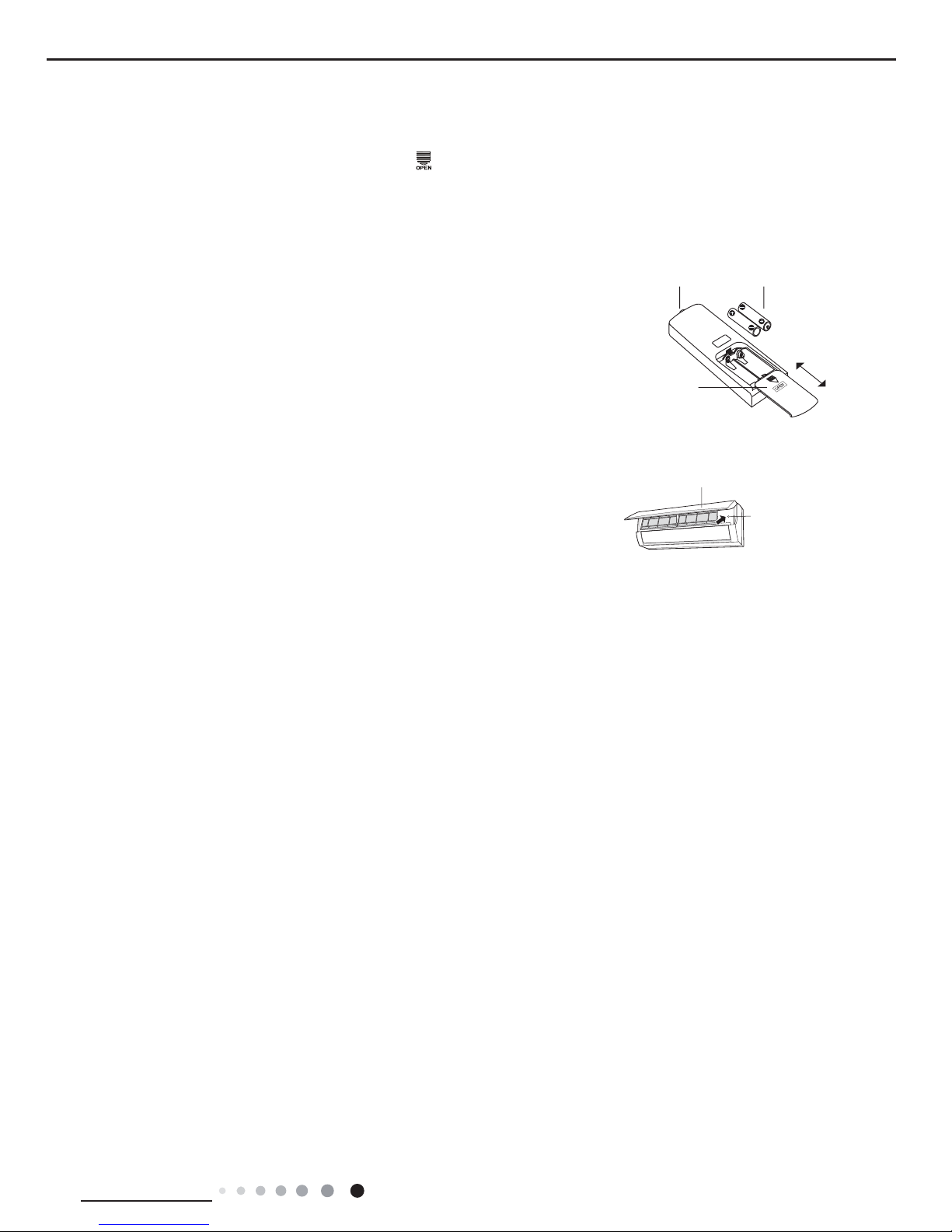
1.Press the back side of remote controller marked with“ ”as shown in the fi g, and then push out the cover
of battery box along the arrow direction.
2. Replace two 7# (AAA 1.5V) dry batteries, and make sure the position of “+” polar and “-“ polar are correct.
3. Reinstall the cover of battery box.
Note:
◆
During operation, point the remote control signal sender at the receiving window on
indoor unit.
◆
The distance between signal sender and receiving window should be no more than
8m, and there should be no obstacles between them.
◆
Signal may be interfered easily in the room where there is fl uorescent lamp or wireless
telephone; remote controller should be close to indoor unit during operation.
◆
Replace new batteries of the same model when replacement is required.
◆
When you don’t use remote controller for a long time, please take out the batteries.
◆
If the display on remote controller is fuzzy or there’s no display, please replace batteries.
If remote controller is lost or damaged, please use auxiliary button to turn on or
turn off the air conditioner. The operation in details are as below: As shown in the
fi g. Open panel, press aux. button to turn on or turn off the air conditioner. When
the air conditioner is turned on, it will operate under auto mode.
Replacement of Batteries in Remote Controller
Emergency Operation
Signal sender
Battery
Cover of
battery box
Remove
Reinstall
Emergency operation
switch
Panel
26
Technical Information
Service Manual
6.2 Brief Description of Modes and Functions
1. Temperature Parameters
Indoor preset temperature (T
preset
)
Indoor ambient temperature (T
amb.
)
2. Basic Functions
Once energized, in no case should the compressor be restarted within less than 3 minutes. In the situation that memory
function is available, for the first energization, if the compressor is at stop before de-energization, the compressor will be
started without a 3-minute lag; if the compressor is in operation before de-energization, the compressor will be started with
a 3-minute lag; and once started, the compressor will not be stopped within 6 minutes regardless of changes in room
temperature;
(2) Dehumidifying Mode
Working conditions and process of dehumidifying
If T
amb
.T
preset
, the unit will enter cooling and dehumidifying mode, in which case the compressor and the outdoor fan will
operate and the indoor fan will run at low speed.
If T
preset
-2 T
amb
.T
preset
, the compressor remains at its original operation state.
If T
amb
.< T
preset
-2 , the compressor will stop, the outdoor fan will stop with a time lag of 30s, and the indoor fan will
operate at low speed.
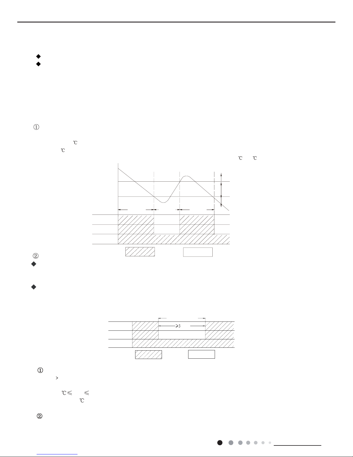
(1)COOL mode
The condition and process of cooling
If T
amb.≥Tpreset
COOL mode will act, the compressor and outdoor fan will run, and the indoor fan will run at the set
speed.
If T
amb.≤Tprese
t-2
, the compressor will stop, the outdoor fan will delay 30 seconds to stop, and the indoor fan will
run at the set speed.
If Tpreset-2 ≤T
amb
≤T
preset
, the unit will keep running in the previous mode.
In this mode, the reversal valve will not be powered on and the temperature setting range is 16 ~30 .
Protection function
Overcurrent protection
If total current is high, the compressor will run in limited frequency. If total current is too high, the
compressor will stop, the
outdoor fan will delay 30 seconds to stop, indoor unit will display E5 and outdoor
yellow light will blink 5 times.
Antifreezing protection
When the antifreezing protection is detected, the compressor will stop, the outdoor fan will stop after 30 seconds, and the
indoor fan and swing motor will keep running in the original mode. When antifreezing protection is eliminated and the
compressor has stopped for 3 minutes, the compressor will resume running in the original mode.
Protection
Protection is the same as that under the cooling mode.
During antifreeze protection
Compressor
Outdoor fan
Indoor fan
min
Preset speed
Run Stop
Tpreset
Tpreset –2 ˚C
Compressor
Outdoor fan
Indoor fan
Run
Tamb.
Stop
Stop cooling
Start cooling
Original operating status
≥ 6 min. ≥ 3 min. ≥ 6 min.
Setting fan speed
 Loading...